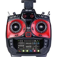
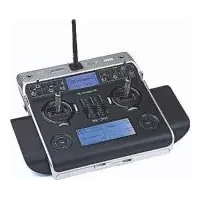
mz-32 HoTT - Remote control toy GRAUPNER - Free user manual and instructions
Find the device manual for free mz-32 HoTT GRAUPNER in PDF.


| Product Type | Remote Control Transmitter |
| Brand | Graupner |
| Model | mz-32 HoTT |
| Channels | 32 |
| Telemetry | HoTT (Hopping Telemetry) |
| Display | Color LCD, 320x240 pixels |
| Operating Frequency | 2.4 GHz |
| Modulation | FHSS |
| Dimensions (approx.) | 200 x 180 x 80 mm |
| Weight (approx.) | 850 g (with battery) |
| Power Supply | Internal 2S LiPo 7.4V or external 6-8.4V |
| Battery Capacity | 5000 mAh (typical) |
| Memory Slots | 100+ model memories |
| Programming | Advanced mixing, curves, sequencers |
| Gimbal Type | Hall sensor, ball bearing |
| Range | Up to 2 km (line of sight, depending on receiver) |
| Maintenance & Cleaning | Wipe with dry, soft cloth; avoid moisture and solvents |
| Storage | Dry place, temperature 0-40°C, battery removed for long term |
| Safety | Not a toy for children under 14; follow RC regulations |
| Spare Parts & Repairability | Available from Graupner service centers; modular design |
Frequently Asked Questions - mz-32 HoTT GRAUPNER
User questions about mz-32 HoTT GRAUPNER
0 question about this device. Answer the ones you know or ask your own.
Ask a new question about this device
Download the instructions for your Remote control toy in PDF format for free! Find your manual mz-32 HoTT - GRAUPNER and take your electronic device back in hand. On this page are published all the documents necessary for the use of your device. mz-32 HoTT by GRAUPNER.
USER MANUAL mz-32 HoTT GRAUPNER
natural_image
Technical line drawing of a multi-rotor control console with dials, motors, and display panels (no text or symbols)CE
Graupner
Table of contents
Introduction .... 5
Service centre .... 5
Intended use 6
Target group 6
Package content 6
Technical data 7
Symbol description 7
Safety notes 8
For your safety by handling the transmitter 8
For your safety! Handling the battery. 9
Description of the transmitter 11
Control elements on the transmitter 11
Transmitter Front 12
Transmitter Backside....13
Connections and fixtures....14
Attaching the transmitter neck-strap 14
AUDIO connection 14
DATA connection....14
COM connection....14
DSC connection....14
Micro USB connection 14
Transmitter preparation....16
Control stick....16
Adjusting the length of the control sticks....16
Neutralizing the control sticks....16
Brake spring and ratchet 16
Control sticks centering force....16
Transmitter power supply....17
Installing the battery....17
Charge the battery....17
Removing the transmitter battery....17
Low voltage warning 17
Battery use timer....17
Starting up the transmitter 18
Switch on transmitter 18
Initial setup of the transmitter .....18
Switch off the transmitter....21
Use and menu functions....21
Operating the displays....21
Change current stick mode....22
Change Stick Mode Preset....22
Rename Model....22
Creating a New Model....23
Keys to the left of the display 24
Keys to the right of the display 24
Screen lock 24
Output Swap 24
Symbols in the main display ....25
Receiver Binding 26
Bind Group 26
Range test 27
Digital switch 28
Setting control and mixer characteristics.... 30
Stick calibration 32
Servo display 33
Telemetry 34
Select Rx 34
Telemetry Cycle 35
RF status 35
SETTING & DATA VIEW 36
Digital switch 38
Firmware update 40
Forced update 42
SIMPLIFIED DECLARATION OF CONFORMITY 46
Notes on environmental protection 47
Care and maintenance 47
Warranty conditions 47
Introduction
Thank you for purchasing a Graupner mz-32 HoTT transmitter.
To get the most out of your mz-32, read the manual carefully before use and operation. If you experience any trouble during operation, consult this manual first or ask assistance from your dealer or Graupner Service Centre.
Due to technical changes, the conetnt of this manual may change without prior notice. You can stay up to date by checking periodically our website at www.graupner.com.
This product complies with national and European legal requirements.
To maintain this condition and to ensure safe operation, you must read and follow this user manual and all the safety notes before using the product!

Note
This manual is part of the product. It contains important information concerning operation and handling. Keep these instructions for future reference and give it to third person in case you transferred the product.
Servic Center
Germany, Ostria, Netherlands
D-Power Modellbau
Sürther Straße 92-94
50996 Köln
Deutschland
www.d-power-modellbau.com
Robbe Modellsport
Industriestraße 10
Graupner in Internet
For the service centes outside the avobe countries please refer to our website www.graupner.com
Intended use
This transmitter system must only be used for the purpose specified by the manufacturer for operation of remote control models without passengers. Any other type of use is impermissible and may cause significant property damage and/or personal injury. No warranty or liability is therefore offered for any improper use not covered by these provisions.
In addition, it is explicitly pointed out that you must inform yourself about the laws and regulations applicable at your respective starting point before starting the remote control operation. Such conditions may differ from state to state, but this must be followed in every case.

Note
Read through this entire manual before you attempt to install or use the transmitter.
Target group
The item is not a toy. It is not suitable for children under 14. The operation of the transmitter must be performed by experienced modelers. If you do not have sufficient knowledge about dealing with radio-controlled models, please contact an experienced modeler or a model club.
Package content
• Transmitter mz-32 HoTT
• Transmitter display and programming stand
- USB cable
• USB adapter for receiver and sensor updates
• 1s3p LiHV transmitter battery with 9000 mAh
- Transmitter strap
- Aluminum case
• Transmitter manual

Note
Graupner works continuously to the further development of the products. We must therefore reserve the right to change the scope of delivery in terms of form, technology and equipment.
Technical data
Transmitter mz-32 HoTT
| Frequency band 2,4 | .. 2,4835 GHz |
| Modulation FHSS | |
| Transmitting power | 100 mW EIRP |
| Control functions | 32 functions of which 8 can be trimmed64 switch functions |
| Temperature range - | 10 ... +55 °C |
| Antenna 1 linear and | 1 circular polarized, withadjustable angle, integrated antenna |
| Operating voltage 3.6 | ... 4.35 V |
| Power consumption | 480 to 1100 mA |
| Dimensions Approx. | 210 x 195 x 105 mm |
| Weight approx. 1120 | g with battery |

Note
The technical data of optionally available receivers can be found in the related receiver system manual.
Symbol description

Always observe the information indicated by this warning sign. Particularly those which are additionally marked with the words CAUTION or WARNING. The signal word WARNING indicates the potential for serious injury, the signal word CAUTION indicates possibility of lighter injuries.

The signal word Note indicates potential malfunctions. Attention indicates potential damages to objects.
Safety notes

These safety instructions are intended not only to protect the product, but also for your own and other people's safety. Therefore please read this section very carefully before using the product!
- Do not leave the packaging material lying around, this could be a dangerous toy for children.
- Persons, including children, with reduced physical, sensory or mental capabilities, or lack of experience or knowledge, or not capable to use safely the transmitter must not use the transmitter without supervision or instruction by a responsible person.
- Operation and use of radio-controlled models needs to be learnt! If you have never operated a model of this type before, start carefully and make yourself familiar with the model's reactions to the remote control commands. Proceed always responsibly.
- Protect all equipment from dust, dirt, moisture. All equipment must be protected from vibration as well as excessive heat or cold. The models may only be operated remotely in normal outside temperatures such as from -10°C to +55°C.
- First, always perform a range and function test on the ground before you start using your model. Only so you can grant a safe use!
- Always use all your HoTT components only with the latest firmware version.
- If you have questions which cannot be answered by the operating manual, please contact us or another expert in the field.
For your safety by handling the transmitter

WARNING
- Also while programming the transmitter, make sure that a motor connected in the model cannot accidentally start. Disconnect the fuel supply or drive battery beforehand.
- Never program your transmitter while normally using the model. This can result in both inattention when controlling and incorrect programming.

CAUTION
Avoid every kind of short-circuit in all sockets of the transmitter and of the receiver! Risk of fire! Use only the suitable connectors. In no case the electronic component of the transmitter or of the receiver may be changed or modified. Any interference will void the warranty.

Note
During transport, protect the model and the transmitter from damages.
For your safety! Handling the battery.

CAUTION
- Protect all equipment from dust, dirt, moisture. Only use in dry locations.
- Do not use any damaged battery.
- Any alterations to the battery can cause serious injury or burns.
- Batteries may not be heated, burned, short-circuited or charged with excessive current or with reversed polarity.
- Combustible or highly flammable objects are to be kept away from the charging area.
- Never leave the charger unattended when it is connected to the power supply.
- Please charge your batteries only in rooms fitted with a smoke detector.
• Always charge the battery with a suitable charger. - The maximum quick charging current specified for the respective cell type may not be exceeded.
- If the battery heats up above 60irc C while it is being charged, stop charging and let the battery cool down to approximately 30 - 40irc C.
- Never charge batteries that have already been charged or hot ones. If a cell in a battery pack has become particularly hot following a quick-charge process, this may indicate a defect in that cell. Do not use the battery pack any more!
- The batteries may not be modified. Do not directly solder or weld the cells.
- If handled improperly, there is a danger of fire, explosion, irritation and burns.
Special instructions
- To charge and discharge batteries, only use specifically designed chargers/dischargers with balancer connector.
Safety notes for storing batteries
- Batteries may only be stored in dry rooms with an ambient temperature of +5°C to +25°C.
- If the LiPo battery must be stored for a longer period, the voltage per cell should be about 3.8V. If the cell voltage drops below 3 V,
they must be recharged immediately. Deep discharge makes the battery short-term, longer storage in discharged as well as fully charged state make the battery in the long term useless.
Description of the transmitter

Control elements on the transmitter
| 1 | 3 w a y s w i t c h W |
| 2 | 2 wayswitch W |
| 3 Digital button DT7 | |
| 4 | P r oportional dial DV3 |
| 5 Foldable transmitter antenna | |
| 6 | T r a n s m i tter handle |
| 7 | P r oportional dial DV4 |
| 8 Digital button DT8 | |
| 9 3 way switch SW 8, top push-switch, bottom latch-ing-switch | |
| 10 3 way switch SW 7 | |
Transmitter Front

| 1 Display | |
| 2 Scroll through menu pages | |
| 3 Scroll through menu pages | |
| 4 Scroll through menu pages | |
| 5 | Trim button of the left control stick |
| 6 | L e ft control stick |
| 7 | P r oportional dial DV1 |
| 8 | 3 w a y s w i t c h $ |
| 9 3 way switch SW 8, 1x push-switch, 2x latching-switch | |
| 10 Digital button DT5 | |
| 11 Digital button DT6 | |
| 12 3 way switch SW 3 | |
| 13 3 way switch SW 4 | |
| 14 Proportional dial DV2 | |
| 15 Right control stick | |
| 16 | Trim button of the right control stick |
| 17 Eyelet for transmitter strap | |
| 18 Direct recall of the servo display | |
| 19 Direct recall of the "SETTING & DATA VIEW" | |
| 20 Menu button | |
| 21 ON/OFF switch | |
Transmitter Backside

| 1 | B a ttery case cover |
| 2 Gimbal tension screw for horizontal control function | |
| 3 no function | |
| 4 Gimbal tension screw for vertical control. Lower screw is for tension of the control stick | |
| 5 | P r oportional rotary control LV2 |
| 6 Inner screw adjusts brake force Outer screw adjusts ratchet's strength | |
| 7 | T r a n s m i tter handle |
| 8 Foldable transmitter antenna | |
| 9 | Cover flap over audio, COMM, DATA and DSC connection |
| 10 Inner screw adjusts brake force Outer screw adjusts ratchet's strength | |
| 11 Proportional rotary control LV1 | |
| 12 Gimbal tension screw for horizontal control function | |
| 13 Gimbal tension screw for vertical control. Lower screw is for tension of the control stick | |
| 14 no function | |
| 15 Cover of the USB connection | |
Connections and fixtures
Attaching the transmitter neck-strap
At the top of the transmitter there is an eyelet for attaching a neck strap.
AUDIO connection

The port for a 3.5 mm jack is located on the back of the transmitter under the upper cover flap.
As soon as a headphone is connected, the loudspeaker built into the transmitter is muted and the transmitter's sound and voice announcements are output through the headphones.
The volume can be adjusted in the submenu "Volume" of the "System" menu.
DATA connection
The DATA connection is suitable for connection of a smart box or an external module. If necessary, this port can also be switched to output a digital SUMD signal.
The corresponding setting is made in the submenu "I/O config." of the system menu, see below under DSC connection.
COM connection
Serial interface for future use
DSC connection

flowchart
graph TD
    A["I/O Set"] --> B["Before Mix ← PPM In"]
    B --> C["Before Mix → PPM Out"]
    C --> D["DATA"]
    D --> E["SUMD 8ch"]
    E --> F["..."]
    F --> G["DATA"]
    G --> H["5V +"]
    H --> I["D.S.C"]
    I --> J["?"]
    J --> K["83%"]
Through a DSC cable this port can be used for a simulator or for Teacher/Student mode.
If necessary, switch to the required DSC operating mode in the "I/O Config." submenu of the system menu.
To ensure a correct DSC connection, observe the following
- Perform any necessary settings in the menu.
- Connect one end of the DSC cable in the DSC port of the switched-off transmitter and the other end to the device to be connected.
- Turn the transmitter on.
Micro USB connection
The USB cable supplied with the is plugged into this socket.
Charging the transmitter battery

Note
Once connected to a PC or other USB power source, a yellow LED should be lit solidly to the left of the mz-32 HoTT's micro-USB port. If this LED flashes yellow or is even dark, the power source is too weak to charge the transmitter.

• Transmitter switched off
Once the transmitter is connected to a suitable USB power source the charging process begins.
Depending on the current charge status of the transmitter battery, the bezel of the ON / OFF switch will flash approximately every 2 seconds in different colours and with varying frequency. As soon as the bezel glows solid green, the battery is fully charged. The charging process is complete.
• Transmitter switched on
After connecting the transmitter to a USB power source, the current display switches to the display shown on the left.
Tapping the left "Charge" field starts the charging process on a suitable charger and tapping this field again or disconnecting the USB cable stops the process.
Tapping the "USB" symbol in the upper left corner returns to the original display, which means that the mz-32 HoTT transmitter can also be used "normally" during the charging process. Only the red flash in the battery symbol in the upper right corner of the display indicates that the charging process is still running.

WARNING
The charger should always be supervised during charge and it should be used only in rooms fitted with a smoke detector.
Mass storage memory
If the mz-32 HoTT transmitter is connected to a compatible PC and the "Mass storage" field is activated by tapping, the memory of the transmitter can be accessed from the PC. For example, to copy screenshots or model data from the transmitter to the PC or MP3 or software updates to the transmitter.

Note
Even if the transmitter can no longer be switched on, the mass memory can still be accessed in special cases, see under "Forced starting in the USB mode Mass storage step-by-step" in the section "Firmware update".
Joystick
As soon as the transmitter is connected to a PC via the micro USB port of the transmitter and "JOYSTICK" is selected by tapping, the connected PC recognizes the transmitter as a joystick.
The standard setting suitable for the most flight simulators is 0% to 100%.
COM Port
Serial interface for future use
Transmitter preparation
Control stick
Adjusting the length of the control sticks

natural_image
Technical line drawing of a mechanical assembly with arrows indicating motion or force direction (no text or symbols)Both sticks can be adjusted in length: By holding the lower half and turning the upper part of the knurled handle, the screw is loosened.
The control stick is extended or shortened by turning it up or down and then fixed by screwing each against each other of the upper and lower part of the handle.
Neutralizing the control sticks
Both control sticks can be set from neutralizing to non-neutralizing and vice versa. Consult the transmitter backside diagram to locate the corresponding set screws.
The respective screw must be turned clockwise until the control stick is free to move from stop to stop or counterclockwise until the control stick is again self-neutralizing.

Note
Which of the two control sticks is to be switched to non-neutralizing also depends on the choice of the control mode, see under "Commissioning the transmitter".
Brake spring and ratchet
On both control sticks, the braking force and strength of the ratchet can be adjusted independently. Consult the transmitter backside diagram to locate the corresponding set screws.
The inner set screw sets the braking force and the outer set screw sets the strength of the ratchet of the vertical control direction of the respective control stick.
Control sticks centering force
The control sticks' restoring force can also be adjusted. Consult the transmitter backside diagram to locate the corresponding set screws.
By turning the respective set screw the spring force can be adjusted:
Right turn = return harder
Left turn = return softer
Transmitter power supply
The mz-32 HoTT transmitter is normally delivered with a 9000 mAh 1s3p LiHV battery.
Installing the battery

Note
Pay attention when inserting the battery to the correct position and make sure the contacts are solid. Interruptions of the power supply to the transmitter during the use of the models can lead to serious danger to yourself and to other people!

Insert the two connection plugs of the transmitter battery into the battery connection sockets with the correct polarity. The corresponding symbols are engraved above the two connection sockets: Red = + Black/ Brown = -
Charge the battery
The transmitter battery is charged by means of the micro-USB socket on the back of the transmitter. Further details can be found in the section "Charging" under "micro USB socket".
Removing the transmitter battery
Open the battery case cover. Lift the battery and then carefully remove the plugs of the power cable.
You can charge the battery outside the transmitter. Consult your charger instructions for proper charging.
Low voltage warning
The supply voltage of the transmitter must be monitored during operation. If it drops below an adjustable capacity limit which by default is 20%, an appropriate warning message will sound continuously.
Stop operation of your transmitter and charge the battery!

Attention
As soon as the supply voltage of the transmitter falls below 3.6 V, the transmitter switches off automatically without further warning.
Battery use timer
The battery used time is added each time the transmitter is switched on. After each charge or battery exchange the timer is reset to "00:00". However, this only happens if the battery voltage is noticeably higher than before. By default, the battery service timer as well as the model operating time can be found in the submenu "Clock Info" of the basic menu. These two clocks can also be installed as widgets on one of your user widget decks.
Starting up the transmitter
Switch on transmitter
Pressing the front ON / OFF switch for about 1 second switches the mz-32 HoTT transmitter on.
Initial setup of the transmitter
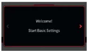


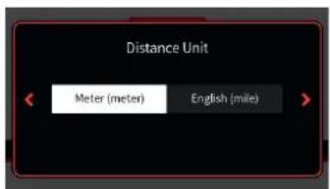


If the transmitter is still in the delivery status or the transmitter was previously reset to factory settings in the "Info & Update" menu, an almost self-explanatory wizard starts immediately after the transmitter is switched on to obtain user settings preferences.
The questions of the first four displays should be selected based on your personal preferences. Please note that all these settings can be later changed in the system menu.
Tapping the symbol “>” at the right side of the display switches to the next display and tapping the symbol “<” at the left side switches backward to the last display.
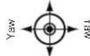
Control modes
• (Fixed-wing models)

(Helicopter models)


| MODE 1 (Throttle/Pitch right) | MODE 2 (Throttle/Pitch left) | ||
| Nick | Throttle/Pitch | Throttle/Pitch | Nick |
 | Roll  | Yaw  | Roll -  |
| Nick | Throttle/Pitch | Throttle/Pitch | Nick |
| MODE 3 (Throttle/Pitch right) | MODE 4 (Throttle/Pitch left) | ||
| Nick | Throttle/Pitch | Throttle/Pitch | Nick |
 | Yaw  | Roll  | Yaw -  |
| Nick | Throttle/Pitch | Throttle/Pitch | Nick |


| MODE 1 (for/backward right) | MODE 2 (for/backward left) | ||
 |  |  |  |
| forward/backward | forward/backward | ||
| MODE 3 (for/backward right) | MODE 4 (for/backward left) | ||
 |  |  |  |
| forward/backward | forward/backward | ||

Notes
- The control mode selected during setup of the transmitter is stored as a default for models to be set up in the future. Changing the default mode setting can be done in the "Control Mode Preset" option of the "System Config." Submenu of the system menu.
- Within a model memory, the control mode can be also changed at any time in the last value field of the sub-menu "Model Type" of the basic menu.
- Depending on the choice of a control mode, one of the two control sticks may also need to be switched to non-neutralizing, see above under "Neutralizing the control stick".
- Not only the presetting of the control mode but also the language setting can be adapted to the current needs in the submenu "System Config." of the system menu as well as date and time in the submenu "Clock Info" of the basic menu.


Date & time
In this display, the current date and time is entered or corrected as part of the initial setup of the transmitter.
Setting date and time step-by-step
- Tap on the desired value field.
This is displayed in white and selection fields are displayed at the bottom of the display. - Use the left "√" or central "^" button to select the desired value.
- If necessary proceed similarly with the other value fields.
- Touching the right tick closes the current display and switches to the next, the last one.
Touching "Ok" restarts the transmitter and after the start display, the factory pre-configured first home page appears.
Main menu
The main display is designed around user editable display widgets that can be changed and adapted to your own personal needs. There are in total six editable decks that can be accessed with the left/right arrow keys on the radio.
Instructions for creating and modifying decks can be found in the help menu or by following our online video tutorials.
System help
Accessing the context sensitive help is done in each menu by tapping the top right ⑦ of the display. If required, such help pages can also be created and stored by the user in the appropriate directory:
To create your own help page, you can use any paint program such as "Paint" that comes standard with Windows 10. There is also a free downloadable version from the Microsoft Store called Paint 3D.
A new page in landscape format with 440 x 232 pixels can be created in Paint, Paint 3D or in any other pixel editor. After creating any type of content, save it in "BMP image" format under "Save as" with the file type "24-bit bitmap (*.bmp; *. Dib)". In Paint 3D, under "Save as file" select "Others" and then as storage format "2D-Bitmap (*.bmp)". The storage location is the corresponding subdirectory of the "Help" directory of the transmitter and the file name is the next free three-digit number.
Switch off the transmitter
Press the front ON / OFF switch and hold it until the "Switch off" message display appears. Tapping "back" stops the process. Touching "OK" switches off the transmitter. Alternatively, press and hold the ON / OFF switch until the transmitter shuts off.
Use and menu functions
Operating the displays


The operation of the display is analogous to the operation of other touch-sensitive displays, by tapping the desired option with the fingertip or with a pen suitable for capacitive displays. The only exceptions are the status indicators of the six freely configurable main displays, which are outlined in red top left.
Note
When the transmitter is on an insulating surface, e.g. on a wooden table, do not tap too strong on the display. The resulting larger finger surface on the screen can result in un-responsive behavior of the screen.

Touching the "Menu" field at the bottom right of the main display changes to the last tab of the four tabs or menu lists labeled "Basic", "Function", "Special" and "System".
Tapping a tab changes to the corresponding menu list.
Tapping a menu opens the corresponding menu, for example the sub-menu "Model Type".

The same principle is used to setup the desired model type. In case of doubt, context-sensitive help can be called via the symbol ? for further assistance.
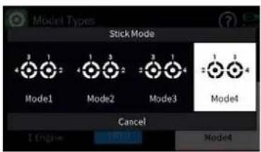
Change current stick mode

Change Stick Mode Preset

Rename Model


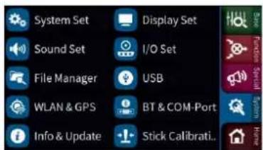
The stick mode entered as part of the initial setup of the transmitter is saved as a default in the "System Config." menu and will be automatically used with all models when newly created.
You can still change the mode (MODE1, MODE2 ...) independently from the system settings. This can be done in the model types menu by swiping to the end of the model properties bar and tapping on the "Stick Mode" icon.
Individual stick mode change step-by-step
- Tap the green "Basic" menu tab.
- Tap on the "Model Types" icon.
- Swipe the model properties bar to the left or use the lower left key to go to the end of the selection list.
-
Tap on the "Stick Mode" icon. The selection window "Stick Mode" will show.
-
Select the desired stick mode or tap cancel to return to the previous display without changing the stick mode.
Change stick mode preset step-by-step
- Tap the blue "System" menu tab.
- Tap the icon "System Set" in the top left corner.
- Tap the "Stick Mode Preset" field and select the new default stick mode for your transmitter. New models will be created with this new stick mode preset.
Rename model step-by-step
- Tap the green "Basic" menu tab.
- Tap the "Model Types" icon.
- Touch the field to the right of "Name".
A small keypad will show - Change the model name with the keypad keys.
Upper and lower case as well as numbers and special characters can be used. - Confirm the model name by tapping the ENTER symbol at the bottom right or cancel the by tapping the "x" in the upper right corner.
Creating a New Model


Create new model step-by-step
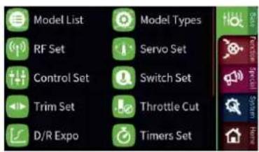
- Tap the green "Basic" menu tab.
- Tap the "Model List" icon.
- Tap the model number in the "No." column.
At the bottom of the display a bar with symbols is displayed. - Touch the plus sign and follow the next steps.
Delete model step-by-step
- Tap the green "Basic" menu tab.
- Tap the "Model List" menu tab.
- In the "No." column, touch the model number of the model to be deleted.
- Touch the "Basket" icon.
A safety dialog will be displayed.

- Tapping the OK button will delete the model. Tap Cancel to abort the delete operation.

Note
The currently active model cannot be deleted. To delete the active model change to a different model first.
Keys to the left of the display

Hereinafter referred to as upper, center and lower selection keys. These keys are used to scroll through lists, columns, etc., in the same way as their arrow directions.
- Log function
Pressing the lower left button for about one second switches the logging function of the transmitter ON or OFF. You can also assign your own key combination to switch data logging ON or OFF.
Keys to the right of the display
• Upper Key Switches between "Servo display" and last active menu position
- Center Key Switches between the "ASCII" screen of the telemetry menu and last active menu position
- Lower Key Switches between active widgets deck and last active menu
Screen lock

In the basic display of the transmitter, the input lock of the screen is activated by pressing the two lower selection keys simultaneously for approx. 1 second.
- The key lock function is displayed by a lock symbol. The controls remain operational.
- Pushing the two lower selection buttons again for approx. 1 second releases the lock again.
Output Swap

Since the transmission of the control channels to the receiver is optimized on the transmitter side, taking into account the model-specific requirements and channels used, all required control channels / outputs must be correspondingly assigned in the "Output Swap" menu.

This assignment occurs automatically during the creation of a model memory and as a result of a manual renaming of the required servo outputs in the submenu "Servo Set" of the basic menu.
Used but not renamed accordingly control channels / outputs are therefore possibly in this menu either assigned manually or by tapping the symbol ☑ on the top of the display, the display "Auto Mapping" appears and then an automatic assignment is triggered by tapping the blue field.
Symbols in the main display

| 1 RF | status of the transmitter |
| 2 RF | status of the receiver |
| 3 Screen lock on/off | |
| 4 | U S B c onnection connected/not connected |
| 5 Headphones connected/not connected | |
| 6 DSC cable connected/not connected | |
| 7 Bluetooth on/off | |
| 8 GPS signal available/not available | |
| 9 WLAN connected/not connected | |
| 10 Data logging on/off | |
| 11 Widget and data clear icon | |
| 12 Help icon | |
| 13 Battery status, tapping switches between % and Volt | |

Note
All other indications in the display are freely interchangeable and are stored model-specifically.
Receiver Binding
![(q1) RF Set Modulation Bind Group Bind Rx T. sel HoTT A0 Rx1 --- □ RF Transmit Range Test Rx2 --- □ Off sell [99 sec] Rx3 --- □ Auto RF On Tele. Speed Rx4 --- □ Off Always Rx4 --- □](/content/2026/06/1369214/images/4790702999ef63d65eb3c452bb6fd750a0f3cf59d4334b01445b81889e21a236.jpg)
To establish a connection with the transmitter, a Graupner HoTT receivers must first be "bound" to at least one model memory. This process is generally called "binding" and it needs to be repeated each time a new receiver is installed in a model.
By default, the "binding" of a receiver is always carried out as part of a so-called bind group. When binding an unbound model memory, the next free bind group is automatically proposed. Each time the proposed bind group is accepted the model will have an exclusive bind with that group therefore, a model-specific binding takes place.
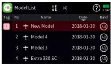
The corresponding bind ID is shown in the "Bind" column at the right edge of the model list. Alternatively, a model memory may also be bound "globally" or within a particular binding group.
Bind Group
![(p) RF Set Modulation Bind Group Bind Rx T. sell HoTT A0 Rx1 --- □ RF Transmit Range Test Rx2 --- □ (●) Off [99 sec] Rx3 --- □ Auto RF On Tele. Speed Rx4 --- □ Off Always Rx4 --- □](/content/2026/06/1369214/images/82c2907b2151f1cb180c3534963f58765be2f0b21cb6cbc15f3ff928634a82ce.jpg)
For an unbound model memory, the default is the next free binding group. However, as long as the model memory is unbound, this specification can be changed by tapping the icon on the "Bind Group" field. You can select from the following options:
- "Global" enables the receiver to respond to the transmitter signal on a non-exclusive bases. What this means is that any other receiver that is bounds as global will respond to the transmitter signal of another model memory that was also bound as global. This can be used in situations where for example you have multiple models that are all the same and do not need different model memory settings.
- "Group" enables the receiver to respond exclusively to the group ID assigned during binding. For example if you bound a receiver to bind group A0 that receiver will not respond to a signal from the transmitter of a model memory that was bound global or for example as group C2.
You can bind another model memory also under bind group C2 which will result in one model memory sharing two receivers under a single bind. What it will do is when both receivers are turned on they will respond simultaneously to the same control inputs of the transmitter.
The use case for this is for example during competition when one airplane becomes inoperative and you would like to continue the contest using an identical airplane without switching model memories on your transmitter to avoid losing time. All you need to do is power the other airplane and wait for the receiver to establish the bind

Note
You can view the associated bind group belonging to a memory model in the "Bind" column on the right-hand edge of the "Model List" submenu.

Attention
If you tap on the bind group bind number ID in the “RF Set” menu the transmitter will release the bind from the active model memory provided that RF is switched off.

![(p) RF Set Modulation Bind Group Bind Rx T. set HoTT A0 Rx1 --- RF Transmit Range Test Rx2 --- (●) Off [99 sec] Rx3 --- Auto RF On Tele. Speed Rx4 --- Off Always Rx4 ---](/content/2026/06/1369214/images/dbf0914052bea5a47fd1e5d441877855b3a3fef7862e36d55733c9ca02094edb.jpg)
Binding procedure step-by-step
- Move transmitter and receiver at a moderate distance from each other (30cm or 1ft).
- Switch on the mz-32 HoTT transmitter without switching on the RF or set the RF Transmission to "OFF" in the "RF Set" field of the "RF Set" menu.
- Switch the receiver power system on.
- Put the receiver in bind mode according to its manual.
- In the transmitter display, touch the desired value field "RX1 ... RX4" in the "Bind" column to enable the transmitter-side binding process.
If the bind was successful you will notice in the Rx column of the transmitter the number of receiver channels for example R6, R12 with a highlighted blue background and the LED on the receiver will change its color or state.
In case of an unsuccessful bind change the positions of the devices and repeat the entire procedure.
Delete existing binding step-by-step
- Switch on the mz-32 HoTT transmitter without switching on the RF or set the RF Transmission to "OFF" in the "RF Set" field of the "RF Set" menu.
- In the transmitter display, touch the desired value field "RX1 ... RX4" in the "Bind" column to trigger a transmitter-side binding process. The existing binding is deleted in the course of the binding attempt (receiver has to be switched off for removing the bind)
Range test
When the range test starts, the output of the transmitter decreases significantly. A practical functional test can therefore be performed at a distance of less than 100 m. After the end of the range test, the transmitter switches back to full output power and the range test signal tone stops.
If necessary ask someone for help.
Range test step-by-step
- Verify that the receiver and transmitter are communicating properly and that all control surfaces are functional.
- Place the model on a flat surface (cement, mowed lawn or ground) with the receiver antenna at least 15 cm above ground.
![RF Set Modulation Bind Group Bind Rx T. set HoTT A0 Rx1 R16 ✓ RF Transmit Range Test Rx2 --- On [99 sec] Rx3 --- Auto RF On Tele. Speed Rx4 --- Off Always Rx4 ---](/content/2026/06/1369214/images/7a9aafe24dc64d7a84dd8f2cb6532ea1c6a5424ddaf800f5617a9f0aab6d7a06.jpg)
![RF Set Modulation Bind Group Bind Rx T. sel HoTT A0 Rx1 R16 ✓ RF Transmit Range Test Rx2 --- On [76 sec] Rx3 --- Auto RF On Tele. Speed Rx4 --- Off Always Rx4 ---](/content/2026/06/1369214/images/74e334ffc91da2a117c47164a125b0fe3b0394dca90bd7cf2ceeade3b81a324d.jpg)
- Hold the transmitter at hip level at a slight distance from your body.
- Start the range test in the "RF Set" menu by tapping the icon in the "Range Test" field.
☒ The time display begins to count down and a beep will sound throughout the entire range test.
- Move away from the model within the given 99 seconds range test and move the control sticks while maintaining visual contact.
☒ If you notice an interruption in the connection at any time within a distance of about 50 m, try to reproduce it.
- If possible, switch on an existing motor, in order to additionally check the interference resistance.
- Carry out the extended range test before starting up your model, simulating all the control movements occurring in practice. In order to guarantee a safe model operation, the range must always be at least 50 m on the ground.

CAUTION
Never start a range test on the transmitter during normal model operation!
Digital switch



The transmitter mz-32 HoTT features 64 digital switches. These can be found in the “Special” menu and can be defined, activated and switched in the submenu “Digital Switch”. In addition, each of these 64 Digital Switches can be arbitrarily placed as a widget on one of the widget pages and operated from there.
Available switching functions are:
• ON/OFF switching function
• Pulsating switching function
• Momentary switching function (0-10 seconds)
On the receiver side, these digital switches can be assigned to the respectively desired switching channel. Mapping a digital switch to a receiver channel can be done in the "RF Set" menu or directly on the receiver using the "Telemetry" Setting & Data View ASCII menu.
Notes
- This function is only available with receivers that have been updated with the current firmware release.
- When setting up digital switches verify that only the intended receiver where such assignment are to be made is active. No other receiver should be active.
![RF Set Modulation Bind Group Bind Rx T. sel HoTT A0 Rx1 R16 ✓ RF Transmit Range Test Rx2 --- On sell [99 sec] Rx3 --- Auto RF On Tele. Speed Rx4 --- Off Always Rx4 ---](/content/2026/06/1369214/images/7e57a812dac58082d2349fbd0226c222e65c3e26ae9097de8ab45dc3a1fc2bdf.jpg)


Assign digital switches in "RF Set" step-by-step
- Bind the receiver you wish to assign to a digital switch and verify no other receiver is active.
- Switch to the submenu "RF Set" of the basic menu.
- Select the receiver you would like to use by tapping on the blue field which is the active receiver.
- By tapping the blue field with the receiver type a selection window appears.
- Tap the channel number for which you would like to assign a digital switch.
The tapped field is displayed inverted and a control panel is displayed at the bottom (see left figure).
- Use the "√"- or "▲" buttons to assign the desired Digital Switch to the selected receiver channel.
- In the illustration on the left, for example, the digital switch "D1" is selected at the receiver connection 14 of the receiver (the bound receiver is a GR-32, 16 channel receiver. You can use any HoTT receiver). Touching the check mark in the bottom right confirms the selection.
- If necessary proceed identically with other receiver connections.
-
By tapping on the symbol pulse (n) you can change to level (f) and back to pulse again.
-
When the symbol pulse (n) is selected, servo pulses are output to the corresponding channel output.
- When the symbol level (☐) is selected, the output of the corresponding channel is switched to high or low.
Notes
- Switching to level allows the direct connection of transistors or LEDs to the receiver output via a series resistor.
-
In Graupner receivers GR-12 (#33506), GR-16 (#33508), GR-24 (#33512), GR-32 (#33516) and GR-24 PRO (#33583) as well as GR-16L (#S1021), GR-24L (#S1022) and GR-32L (#S1023) series resistors are allready installed and LEDs can be connected directly between the orange servo pulse wire and the brown or black “-” wire.
-
Touching "OK" completes the process. Touching "Reset" resets the receiver to the default settings.
In both cases, the display will be closed and you will return to the "RF Set" menu.

Assign Digital Switches to a widget step-by-step
- Switch to the submenu "Digital Switch".
- Tap on the first "Act" icon to activate the Digital Switch and select the desired mode (On/Off, Pulse or Flash).
- Connect for example a servo to the channel you designated as Digital Switch.
- Go to the Home page and select an empty deck or available block an bring up the Widget Editor.
- Select the "Digital Switch" widget and tap on DS1 which is the widget we assigned in the previous step.
- Test the operation by tapping on the button. You can change its behavior in the "Digital Switch" submenu.
Setting control and mixer characteristics

Both the control characteristics in the submenu „control setting“ of the basic menu as well as virtually all mixer characteristics are set essentially according to the same principles. The corresponding procedure is shown below with reference to the throttle curve.
However, the settings shown have a purely demonstrative character and in no way correspond to real throttle characteristics!

line
| X-Axis | Y-Axis | |---|---| | -100 | -125 | | 0 | 0 | | 100 | 125 | | +100 | 250 | | +200 | 375 | | +300 | 500 | | +400 | 625 | | +500 | 750 | | +600 | 875 | | +700 | 1000 | | +800 | 1125 | | +900 | 1250 | | +1000 | 1375 | The chart displays a line graph with a separate bar chart below it. The text 'Throttle' is displayed in the top-right corner.Select characteristic curve step-by-step
- Enter the desired submenu.
Here is an example of the submenu "control setting". - In the desired line touch the symbol ⏻ in the "Detail" column. Here is an example of the control function "Throttle". The display shown on the left will be displayed.
-
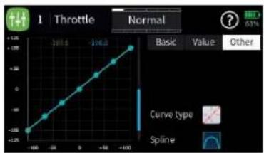
Touch the "Other" field in the upper right corner. The display shown on the left will be displayed.
-
Touch the bright selection field to the right of "Curve type". In rotation procedure, select the desired curve type or the desired control characteristic. The choices are:

line
1 Throttle Normal | X | Y | |---|---| | -100 | -1.25 | | -80 | -0.75 | | -60 | -0.25 | | -40 | 0.25 | | -20 | 0.75 | | 0 | 1.25 | | 20 | 1.75 | | 40 | 2.25 | | 60 | 2.75 | | 80 | 3.25 | | 100 | 3.75 | | Basic Value Other- A linear characteristic without points between the endpoints. This characteristic corresponds to the standard setting.

line
| X | Y | |---|---| | -200 | -1.00 | | -150 | -0.75 | | -100 | -0.50 | | -50 | -0.25 | | 0 | 0.00 | | 50 | 0.25 | | 100 | 0.50 | | 150 | 0.75 | | 200 | 1.00 | The chart displays a single data series with values ranging from approximately -1.00 to 1.00. The chart includes a legend at the bottom: 'Curve type' and 'Spline'. The title 'Throttle Normal' appears in the top-left corner, but it is not explicitly labeled on the graph.- A linear characteristic with 5 points evenly distributed between the endpoints. This characteristic is to be selected as the basis of non-linear characteristics.

- A horizontal curve with a single point in the middle of the control.
line
1 Throttle Normal | X | Y | |---|---| | -100 | -0.24 | | -80 | -0.16 | | -60 | -0.08 | | -40 | 0.00 | | -20 | 0.12 | | 0 | 0.24 | | 20 | 0.36 | | 40 | 0.48 | | 60 | 0.60 | | 80 | 0.72 | | 100 | 0.84 | | 120 | 0.96 | | 140 | 1.08 | | 160 | 1.20 | | 180 | 1.32 | | 200 | 1.44 | | 220 | 1.56 | | 240 | 1.68 | | 260 | 1.80 | | 280 | 1.92 | | 300 | 2.04 | | 320 | 2.16 | | 340 | 2.28 | | 360 | 2.40 | | 380 | 2.52 | | 400 | 2.64 | | 420 | 2.76 | | 440 | 2.88 | | 460 | 3.00 | | 480 | 3.12 | | 500 | 3.24 | | 520 | 3.36 | | 540 | 3.48 | | 560 | 3.60 | | 580 | 3.72 | | 600 | 3.84 | | 620 | 3.96 | | 640 | 4.08 | | 660 | 4.20 | | 680 | 4.32 | | 700 | 4.44 | | 720 | 4.56 | | 740 | 4.68 | | 760 | 4.80 | | 780 | 4.92 | | 800 | 5.04 | | 820 | 5.16 | | 840 | 5.28 | | 860 | 5.40 | | 880 | 5.52 | | 900 | 5.64 | | 920 | 5.76 | | 940 | 5.88 | | 960 | 6.00 | | 980 | 6.12 | | 1000 | 6.24 |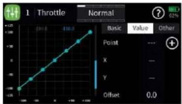
line
| Point | Value | |---|---| | X | - | | Y | - | | Offset | 0.0 |

line
| Point | Value | |-------|-------| | X | 27.0 | | Y | -75.0 |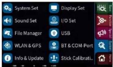
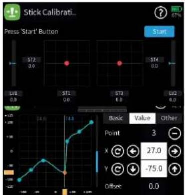
The horizontal characteristic curve can only be moved vertically and thus used, for example, as the basis for speed specifications for speed controllers.
- If necessary, bottom right, in the field to the right of "Spline", select whether the characteristic should be "square" or "rounded".
Set characteristic curve step-by-step
-
Change to the display page "Value".
-
Bring the vertical green line to the desired point with the relevant sensor, in the example with the throttle control stick.
The approached point is displayed in red and on the right the number of the point as well as its coordinates are shown as well as yellow rectangles at the lower and left display edge.
- The selected point can now be moved either horizontally or vertically, and that ...
... either by tapping the symbols← → ↓ ↑ in increments of 0.1%.
... or by moving the respective yellow rectangle horizontally or vertically with a fingertip or a stylus suitable for touch screens.
| | Touching the ico® resets the value of the selected line back to the default value.
Add point step-by-step
- Use the relevant control to move the vertical green line between two points.
As soon as the symbol⊕ is visible on the right edge of the display, another point can be set by tapping the symbol. Up to three more points are possible.
-
If necessary adjust the position of the added point as described above.
-
If necessary proceed identically with further points.
Delete point step by step
- Use the relevant control to move the vertical green line to the point to be deleted.
The selected point is displayed in red and the top right shows the number of the point and the symbol to the right.
- Touching the icon deletes the selected point.
In the picture on the left this would be point 3, for example.
- If necessary proceed identically with further points.
Stick calibration


If the center position of the self-neutralizing control stick does not correspond exactly to 0% control travel, this can be corrected in this menu.
Check the stick calibration step-by-step
- Change to the "Model list" submenu of the "green" basic menu.
- Initialize a free model memory with any model type.
- Do not make any further adjustments and do not adjust trims.
- Call up the "Servo View" menu by pressing the upper button on the right-hand keypad.
- If all self-resetting control sticks are in their respective center position, the display of the control channels 1 ... 4 or 2 ... 4, if the C1 control stick is switched to non-self-neutralizing, should look like in the figure on the left.
- If the display looks like the one shown, everything is fine and the previously saved model memory can be deleted again.
- If the display deviates from the desired values, these can be calibrated on the first display page of the submenu "Switch display" of the "green" basic menu.
Performing stick calibration step-by-step
Stick calibration step-by-step
- Leave the model memory created as described in "Checking the stick calibration step-by-step" above.
- Switch to the "blue" tab of the "System" menu.
- Touch the "Stick Calibration" field right down. This opens the page of the selected menu.
- Tap on the symbol ⭕ on the upper edge of the display and perform the stick calibration following the instructions in the help text:

Servo display


The Servo View monitor can be called upon at any time by pressing the servo monitor key on the right side of the radio.
The view represents the active positions of any control or switch including mixers. The default screen shows channel 1 ... 16. A swipe from the bottom to the top will reveal the additional channels.
The default bar chart view shows the channel position between -150% and +150% and when a control is moved it will show the maximum deflection set for that channel.
When tapping on the Servo View screen the presented view will show a numerical representation of the channels in milliseconds. A value of 1500 ms represents 0% which is the controls middle position.
This view also shows the channel names as assigned by the system or as named by the user.
Telemetry

The telemetry connection between the transmitter and receiver takes place via the return channel of the HoTT receiver defined as the main receiver. If more than one receiver is bound to a model memory, the return channel will be by default the last bound receiver. This assignment can be changed in the submenu “RF Set” in the base menu or at the special “Telemetry” menu.
Depending on the setting of the value field at the “Tele. Cycle” the transmission of telemetry data takes place after each fourth data packet. This also influences the reaction time to control inputs when making setting changes at the ASCII menu when setting up for example a flight controller using the wireless interface. The corresponding delay does not constitute an error

Note
Sensors must always be connected to the main receiver, since only the return channel of this receiver is evaluated by the transmitter.

Attention
Programming on the model or on sensors must not be carried out during ongoing model operation and only when the engine/motor is switched off!
Select Rx
![RF Set Modulation Bind Group Bind Rx T. sel HoTT A0 Rx1 R16 RF Transmit Range Test Rx2 R8 On sell [99 sec] Auto RF On Tele. Speed Rx3 --- Off Always Rx4 ---](/content/2026/06/1369214/images/1add4e35314e8f95040ed0d210d709eadba7b83ede5e127fec850f52d91c6e48.jpg)
Up to four receivers can be bound to a model memory in the sub-menu “RF Set” of the basic menu. However, a telemetry connection can only ever be established to one of these four receivers which as standard is always the last bound receiver. All sensors are to be connected to the receiver that is designated as the receiver from which we expect to receive telemetry information from. This is important in a multi receiver configuration and therefore will require proper planning as to the location of the receiver which should be close to where the telemetry sensors are installed.

In the “RF Set” menu the receiver that has the “T.Sel” field checked is the receiver that provides telemetric information to the transmitter

Viewing telemetric information or settings from additional receivers bound to the model can be done by tapping on the “RX Select” field which will show an list with all active receivers to pick from.

Attention
This also changes the assignment in the column "T. sel." of the submenu "RF Set". After completing the adjustments, it may be necessary to restore the original assignment!
Telemetry Cycle

In those situations where for example two airplane models are about to be operated at close proximity to another controlled by two separate transmitters you may choose to reduce or eliminate the telemetry back channel of one of the models to avoid potential interference. Situations that may need to be evaluated such as with drones that have a separate transmitter for control and camera operations or airplanes that tow or carry other airplanes can be all pick-up interference from the telemetry downlink transmission. Experiment with the proper telemetry period value for your situation.
| Value Description | |
| Always | The transmitter reacts normal to the back-channel of the selected receiver. |
| 4x / 8x | The transmitter reacts to the back-channel of the selected receiver with the chosen delay. |
| OFF | The transmitter telemetry functions are switched off. |
RF status

bar
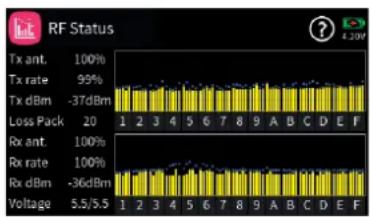
RF Status | Signal | Value (%) | |---|---| | Tx ant. | 100 | | Tx rate | 95 | | Tx dBm | -37dBm | | Loss Pack | 20 | | Rx ant. | 100 | | Rx rate | 100 | | Rx dBm | -36dBm | | Voltage | 5.5/5.5 |This display visualises the quality of the connection between transmitter and receiver. If there is no connection to a receiver, the submenu can be opened, but the displays remains empty. If necessary, switch on your receiver or switch to the right receiver.
- Upper row
Level of channels 1 ... 75 coming from the receiver of the 2.4 GHz band in dBm at the transmitter.
- Lower row
Level of channels 1 ... 75 coming from the transmitter of the 2.4 GHz band in dBm at the receiver.
Note
- The height of the bar is a measure of the reception level expressed as logarithmic values with the unit dBm (1 mW = 0 dBm).
- 0 dBm corresponds to the two baselines in the above graph. Consequently, the level is poorer the higher the bar and vice versa.
- The dots above the bar mark the worst reception levels from the opening of the "RF Status" display. A reset of these points is therefore possible by exiting and recalling this display.
- In addition to the graphic display of the reception level, additional numeric information is provided to the left. This means:
| Value | Description |
| Tx ant. | Quality expressed as a percentage of the signal packages from the receiver arriving at the transmitter |
| Value Description | |
| Tx strength | Quality expressed as a percentage of the signal packages from the transmitter arriving at the receiver |
| Tx dBm Level | in dBm expressed as the percentage of the receiver signal arriving at the transmitter |
| Lost pack. Indicates the number of lost data packets | |
| Rx ant. Quality | expressed as a percentage of the signal packages from the transmitter arriving at the receiver |
| Rx strength | Quality expressed as a percentage of the signal packages from the receiver arriving at the transmitter |
| Rx dBm Level | in dBm expressed as the percentage of the transmitter signal arriving at the receiver |
| Voltage actual | operating voltage of the power supply of the receiving system |
SETTING & DATA VIEW


This display visualises the settings and menus of the connected receiver. If there is no connection to a receiver, the submenu can be opened, but the display window remains empty.
- A detailed description of the submenus of standard receivers such as the GR-12 or GR-16 can be found in the manual of the receiver model as well as in the manuals of the various other Graupner handheld or tray transmitters. The appearances may differ depending on the transmitter model but functionality remains the same. Please note that receivers like the GR-12L, GR-16L, GR24L and GR-32L are functionally the same and therefore there are no operational differences between the models.
- Specialty receivers, such as the receivers GR-18 HoTT (No. 33579 or S1019), are equipped with separate versions of the "SETTING & DATA VIEW" menu. The descriptions of these special submenus are contained in the respective receiver manual.
Function of the cross-shaped keypad
• left and right selection keys
Tapping on the left/right keypad screen will bring up the next page available for the selected receiver or module
If there is only one angled bracket shown at the upper screen next to the content window it will indicate that the last page of the available menus has been reached.

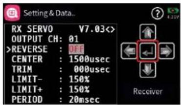



• upper and lower selection keys
Menu lines in which parameters can be changed are indicated by a preceding angle bracket (>) . Tapping on the lower or upper selection button moves this " >" pointer one line down or up.
Lines which cannot be navigated to cannot be changed.
- middle "ENTER" button
Tapping the central button activates or deactivates the value field of a modifiable parameter.
As long as a parameter is displayed inversely, the selected value can be changed with the upper or lower key within the possible setting range.
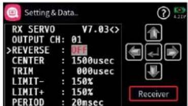
- "RECEIVER" button
If a sensor was connected before switching on the relevant receiver power supply, or if several sensors were connected to the receiver, this is indicated by a green bar at the bottom of the display of the "telemetry" menu, as shown on the left.
To access the telemetry displays of these devices, open the "SETTING & DATAVIEW" display, then tap the value field labelled "Receiver" in the lower right corner and select the desired device in the selection window that appears.
The operation of these displays is the same as described above under "function of the cross-shaped keypad".
Note
All settings made via the "Telemetry" menu in the receiver, such as, fail-safe, servo reverse, end points adjustment, mixer and curve settings, etc. are stored exclusively in the receiver's settings.
Most of these settings can be made directly on the transmitter which is the proper way for setting up your model memories. In case you chose to do this on the receiver you must reinitialize the receiver when installing into another model to avoid taking over settings that may not work with another model
Digital switch
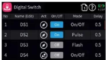
As mentioned earlier in the section “Operation and menu functions”, the transmitter mz-32 HoTT over 64 digital switches. Details can be found in the mentioned section.
On the receiver side, these digital switches can be assigned to the respectively desired switching channel both in the submenu "RF Config." of the basic menu and in the submenu "Setting and data view" of the "Telemetry" menu.
Notes
- This function is only available for selected receivers with current firmware.
- In order to avoid malfunctioning when assigning the digital switches, only the respectively affected receiver may be in operation during their assignment.
Assign digital switch step-by-step
- Commission the desired receiver and, if necessary, switch off any other receivers or otherwise shut them down.
- Switch to the "SETTING & DATAVIEW" submenu of the telemetry menu.
- Use the right selection key to switch to the "RX FAIL SAVE" page.
- In the "OUTPUT CH" line, if necessary, select the receiver output to be switched as described under "Function of the cross-shaped keypad".
- In the figure on the left, this is, for example, the receiver connection 10 of the HoTT receiver currently defined as a telemetry receiver.
- Change to the "INPUT CH" line.
- Press the middle ENTER key to activate the value field.
The value field is displayed inverted: - Select the desired digital switch.
- In the picture on the left this is for example "D01".
- Press the middle ENTER key to complete the process.
The value field is again displayed as "normal". - Eventually use the same procedure with the assignment of further switches.

Firmware update
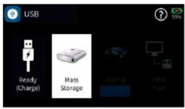
Firmware updates of the transmitter can be done wireless over a WiFi network or via the back of the radio using the micro USB port. When the transmitter is connected to a PC the USB menu is automatically shown. For firmware update select the "Mass Storage" option.
When the “Mass Storage” option is selected your PC will recognize the transmitter as a disk drive.
All required programs and files needed to update your Graupner products can be found both in the directory "Util" on the mass memory of the transmitter as well as online at www.graupner.com.
Copy the software package from the transmitter's mass storage or the Internet to a Windows PC or laptop.

Notes
- Please note that compatible firmware is required for reliable communication between the HoTT components. The programs and files that are required for updates are therefore combined into a single pack that is currently named "HoTT_Software_V4.zip".
- Only operate your transmitter using the current software version.
Copy from mass storage step-by-step
- Connect the mz-32 HoTT transmitter to a Windows PC or laptop via the rear micro-USB port.
- Switch on the transmitter.
- Select "Mass storage" in the automatically displayed selection display.
A message from the operating system "Would you like to check and repair MZ-32 (X :)" on the PC or laptop? Can either be ignored or optionally confirmed.
- In the file explorer of the PC, switch to the drive "MZ-32 (X :)".
- Change to the directory "Util".
- Copy the required files from this directory to the PC or the laptop, unzip and install them if necessary.
Note
If the program "Firmware_Upgrade_gr_Studio" is already installed on the Windows PC or laptop, then only the "Virtual COM Port" driver has to be installed manually and a possible update has to be performed after starting the firmware upgrade program.


Install the software step-by-step
-
Connect the mz-32 HoTT transmitter to a Windows PC or laptop via the rear micro-USB port.
-
Switch on the transmitter.
-
Select "Mass storage" in the automatically displayed selection display.
-
Start the program "Firmware_Upgrade_gr_Studio" on the PC or laptop.
-
Eventually agree to the proposal for a program update.
-
In the section "Transmitter" of the "Firmware_Upgrade_gr_Studio" start the program part "mz-32 Radio Downloader".
- Do not disconnect the link to the computer during the download! Make sure that the link between the transmitter and computer is operational.
-
Start the firmware download by clicking on the download button.
-
Follow the instructions of the program.
-
As soon as the message "complete" appears, the download is complete.
-
In the transmitter display, switch from "Mass storage" to "Done (load)" and tap "USB" in the upper left corner to exit the menu.
Updating the transmitter step-by-step
-
Switch to the "Info % update" submenu of the system menu.
-
Touch the "SD card update" button.
-
Tap on the desired firmware version.
-
Tap tick icon on top right.
The circled check mark is replaced by an "X".
- Touching the "X" symbol or the "Back" button in the upper left corner of the display stops the process.
- Touching the door symbol in the upper right corner of the display starts updating the transmitter.

Note
In the procedure described above, if necessary, also configuration files, language files, help texts, etc. are brought up to date, while in an update made by "WLAN Update" only the transmitter firmware is updated.
Forced update
If a firmware update of the transmitter fails or the transmitter software "hangs up" during the update and the transmitter can no longer be switched off through the central ON/OFF switch, then unplug the transmitter battery. Wait a few seconds, then reconnect the removed battery and do the following:
Forced updating step-by-step
- Press and hold the top two buttons on the left and right of the display while turning on the transmitter.
- As soon as the fence of the central ON / OFF switch lights up orange, press and hold the two middle buttons on the left and right of the display.
If the fence of the central ON / OFF switch turns green, the keys can be released. - Shortly thereafter, the forced update starts with the latest available firmware version in the "Update" directory of the transmitter.
- As soon as the update is successfully completed, the transmitter restarts and it can be used again.
- If the forced update fails due to a missing update file, then proceed as follows:
Forced start in the USB mode "mass storage" step-by-step
- Press and hold the lower two buttons on the left and right of the display while turning on the transmitter.
-
As soon as the fence of the central ON / OFF switch lights up orange, press and hold the two middle buttons on the left and right of the display.
If the fence of the central ON/OFF switch turns red, the keys can be released. -
Following the instructions in the transmitter display, connect the transmitter to the PC or laptop via USB cable.
-
As soon as the connection is established, the message "USB Mass Storage Connected" appears in white text on the transmitter's display.
-
In the file explorer of the PC or laptop appears a drive "MZ-32 (X :).
-
As described above in points 1 to 9 under "Updating the transmitter step-by-step", load a file suitable for updating the mz-32 HoTT transmitter onto the transmitter.
-
Switch off the transmitter by pressing the central ON/OFF switch
-
Disconnect from PC or laptop.
-
As described above, start the "Forced Update".
| 10.5% 10.5% 10.5% 10.5% 10.5% 10.5% 10.5% 10.5% 10.5% 10.5% 10.5% 10.5% 10.5% 10.5% 10.5% 10.5% 10.5% 10.0% 10.0% 10.0% 10.0% 10.0% 10.0% 10.0% 10.0% 10.0% 10.0% 10.0% 10.0% 10.0% 10.0% 10.0% 10.0% 10.0% 12.5% 12.5% 12.5% 12.5% 12.5% 12.5% 12.5% 12.5% 12.5% 12.5% 12.5% 12.5% 12.5% 12.5% 12.5% 12.5% 12.5% 13.75% 13.75% 13.75% 13.75% 13.75% 13.75% 13.75% 13.75% 13.75% 13.75% 13.75% 13.75% 13.75% 13.75% 13.75%, | |||||||||||||||||||||||||||||||
| 10.25.00元/日元 | |||||||||||||||||||||||||||||||

Manufaturer / Manufakturer
GRAUPNER Co. Ltd
Post Code: 14557
202-809, 18, Bucheon-ro 198beon-gil, Bucheon-si,
Gyeonggi-do, South Korea
Sürther Straße 92-94
50996 Köln
Deutschland
www.d-power-modellbau.com
Robbe Modellsport
Contact : support@flashrc.com
Passo Corese (RI) Italy
www.jonathan.it
Contact :
https://shop.jonathan.it/it/contact
Notes on environmental protection

If this symbol is on the product, instructions for use or packaging, it indicates that the product may not be disposed with normal household waste once it has reached the end of its service life. It must be turned over to a recycling collection point for electric and electronic apparatus.
Individual markings indicate which materials can be recycled. You make an important contribution to protection of the environment by utilizing facilities for reuse, material recycling or other means of exploiting obsolete equipment.
Batteries must be removed from the unit and disposed of separately at an appropriate collection point. Please inquire if necessary from the local authority for the appropriate disposal site.
Care and maintenance

The product does not need any maintenance. Always protect it against dust, dirt and moisture.
Clean the product only with a dry cloth (do not use detergent!) lightly rub.
Warranty conditions
grants from the date of purchase of this product for a period of 24 months. The warranty applies only to the material or operational defects already existing when you purchased the item. Damage due to misuse, wear, overloading, incorrect accessories or improper handling are excluded from the guarantee. The legal rights and claims are not affected by this guarantee. Please check exactly defects before a claim or send the product, because we have to ask you to pay shipping costs if the item is free from defects.
These operating instruction are exclusively for information purposes and are subject to change without prior notification. The current version can be found on the Internet at www.graupner.com on the relevant product page. In addition, the company Graupner has no responsibility or liability for any errors or inaccuracies that may appear in construction or operation manuals.
Not liable for printing errors.

- Table of contents
- Introduction
- Note
- Servic Center
- Germany, Ostria, Netherlands
- Intended use
- Target group
- Package content
- Technical data
- Symbol description
- Safety notes
- WARNING
- CAUTION
- Special instructions
- Safety notes for storing batteries
- Transmitter Front
- Transmitter Backside
- Connections and fixtures
- Charging the transmitter battery
- • Transmitter switched off
- • Transmitter switched on
- Mass storage memory
- Joystick
- COM Port
- Transmitter preparation
- Control stick
- Transmitter power supply
- Attention
- Starting up the transmitter
- Control modes
- Notes
- Date & time
- Setting date and time step-by-step
- Main menu
- System help
- Switch off the transmitter
- Use and menu functions
- Operating the displays
- Change current stick mode
- Individual stick mode change step-by-step
- Change stick mode preset step-by-step
- Rename model step-by-step
- Creating a New Model
- Create new model step-by-step
- Delete model step-by-step
- Keys to the left of the display
- - Log function
- Keys to the right of the display
- Screen lock
- Output Swap
- Receiver Binding
- Bind Group
- Binding procedure step-by-step
- Delete existing binding step-by-step
- Range test
- Range test step-by-step
- Assign digital switches in "RF Set" step-by-step
- Assign Digital Switches to a widget step-by-step
- Setting control and mixer characteristics
- Select characteristic curve step-by-step
- Set characteristic curve step-by-step
- Add point step-by-step
- Delete point step by step
- Stick calibration
- Check the stick calibration step-by-step
- Performing stick calibration step-by-step
- Stick calibration step-by-step
- Servo display
- Telemetry
- Select Rx
- Telemetry Cycle
- RF status
- SETTING & DATA VIEW
- Function of the cross-shaped keypad
- • left and right selection keys
- • upper and lower selection keys
- - middle "ENTER" button
- - "RECEIVER" button
- Digital switch
- Assign digital switch step-by-step
- Firmware update
- Copy from mass storage step-by-step
- Install the software step-by-step
- Updating the transmitter step-by-step
- Forced update
- Forced updating step-by-step
- Forced start in the USB mode "mass storage" step-by-step
- Manufaturer / Manufakturer
- Robbe Modellsport
- Notes on environmental protection
- Care and maintenance
- Warranty conditions
Brand : GRAUPNER
Model : mz-32 HoTT
Category : Remote control toy