
MM7025 - Power amplifier MARANTZ - Free user manual and instructions
Find the device manual for free MM7025 MARANTZ in PDF.
| Product type | Power amplifier |
| Brand | Marantz |
| Model | MM7025 |
| Output power (8 ohms) | 140 W per channel |
| Output power (4 ohms) | 200 W per channel |
| Number of channels | 2 |
| Load impedance | 4 to 8 ohms |
| Frequency response | 5 Hz – 100 kHz (±3 dB) |
| Signal-to-noise ratio | 105 dB (IHF-A) |
| Total harmonic distortion | 0.05% (at rated power) |
| Dimensions (W x H x D) | 440 x 123 x 343 mm |
| Weight | 10.2 kg |
| Power supply | 230 V AC, 50/60 Hz |
| Power consumption | 350 W (max) |
| Input connectivity | 2 pairs of RCA jacks |
| Output connectivity | Screw terminals for speakers |
| Main features | High-power stereo amplification, bridged mode possible |
| Care and cleaning | Unplug the device, clean with a soft dry cloth. Do not use chemicals. |
| Safety | Hot surface - do not touch. Do not block ventilation openings. Unplug if not used for extended periods. Do not expose to water. |
| Spare parts and repairability | Contact Marantz after-sales service for any repair or replacement of parts. |
| General information | High-end stereo power amplifier for home theater or hi-fi systems. |
Frequently Asked Questions - MM7025 MARANTZ
User questions about MM7025 MARANTZ
0 question about this device. Answer the ones you know or ask your own.
Ask a new question about this device
Download the instructions for your Power amplifier in PDF format for free! Find your manual MM7025 - MARANTZ and take your electronic device back in hand. On this page are published all the documents necessary for the use of your device. MM7025 by MARANTZ.
USER MANUAL MM7025 MARANTZ
natural_image
Pure electrical circuit lines without any symbolsmarantz®
5 Channel Power Amplifier
MM7055
2 Channel Power Amplifier
MM7025

CAUTION
RISK OF ELECTRIC SHOCK DO NOT OPEN

CAUTION:
TO REDUCE THE RISK OF ELECTRIC SHOCK, DO NOT REMOVE COVER (OR BACK). NO USER-SERVICEABLE PARTS INSIDE. REFER SERVICING TO QUALIFIED SERVICE PERSONNEL.

The lightning flash with arrowhead symbol, within an equilateral triangle, is intended to alert the user to the presence of uninsulated “dangerous voltage” within the product’s enclosure that may be of sufficient magnitude to constitute a risk of electric shock to persons.

The exclamation point within an equilateral triangle is intended to alert the user to the presence of important operating and maintenance (servicing) instructions in the literature accompanying the appliance.
WARNING:
TO REDUCE THE RISK OF FIRE OR ELECTRIC SHOCK, DO NOT EXPOSE THIS APPLIANCE TO RAIN OR MOISTURE.

Hot surface mark
CAUTION:
The top surface over the internal heat sink may become hot when operating this product continuously.
Do not touch hot areas, especially around the “Hot surface mark” and the top panel.
PRECAUTION:
SURFACE CHAUDE. NE PASTOUCHER.
- Read these instructions.
- Keep these instructions.
- Heed all warnings.
- Follow all instructions.
- Do not use this apparatus near water.
- Clean only with dry cloth.
- Do not block any ventilation openings. Install in accordance with the manufacturer's instructions.
- Do not install near any heat sources such as radiators, heat registers, stoves, or other apparatus (including amplifiers) that produce heat.
- Do not defeat the safety purpose of the polarized or grounding-type plug. A polarized plug has two blades with one wider than the other. A grounding type plug has two blades and a third grounding prong. The wide blade or the third prong are provided for your safety. If the provided plug does not fit into your outlet, consult an electrician for replacement of the obsolete outlet.
- Protect the power cord from being walked on or pinched particularly at plugs, convenience receptacles, and the point where they exit from the apparatus.
- Only use attachments/accessories specified by the manufacturer.
- Use only with the cart, stand, tripod, bracket, or table specified by the manufacturer, or sold with the apparatus. When a cart is used, use caution when moving the cart/ apparatus combination to avoid injury from tip-over.
- Unplug this apparatus during lightning storms or when unused for long periods of time.
- Refer all servicing to qualified service personnel.
Servicing is required when the apparatus has been damaged in any way, such as power-supply cord or plug is damaged, liquid has been spilled or objects have fallen into the apparatus, the apparatus has been exposed to rain or moisture, does not operate normally, or has been dropped. - Batteries shall not be exposed to excessive heat such as sunshine, fire or the like.
CAUTION:
To completely disconnect this product from the mains, disconnect the plug from the wall socket outlet.
The mains plug is used to completely interrupt the power supply to the unit and must be within easy access by the user.
PRECAUTION:
FCC INFORMATION (For US customers)
1. PRODUCT
This product complies with Part 15 of the FCC Rules. Operation is subject to the following two conditions: (1) this product may not cause harmful interference, and (2) this product must accept any interference received, including interference that may cause undesired operation.
2. IMPORTANT NOTICE: DO NOT MODIFY THIS PRODUCT
This product, when installed as indicated in the instructions contained in this manual, meets FCC requirements. Modification not expressly approved by Marantz may void your authority, granted by the FCC, to use the product.
3. NOTE
This product has been tested and found to comply with the limits for a Class B digital device, pursuant to Part 15 of the FCC Rules. These limits are designed to provide reasonable protection against harmful interference in a residential installation.
This product generates, uses and can radiate radio frequency energy and, if not installed and used in accordance with the instructions, may cause harmful interference to radio communications. However, there is no guarantee that interference will not occur in a particular installation. If this product does cause harmful interference to radio or television reception, which can be determined by turning the product OFF and ON, the user is encouraged to try to correct the interference by one or more of the following measures:
- Reorient or relocate the receiving antenna.
- Increase the separation between the equipment and receiver.
- Connect the product into an outlet on a circuit different from that to which the receiver is connected.
- Consult the local retailer authorized to distribute this type of product or an experienced radio/TV technician for help.
For Canadian customers:
This Class B digital apparatus complies with Canadian ICES-003.
natural_image
Pure electrical circuit lines without any symbols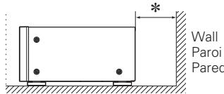
text_image
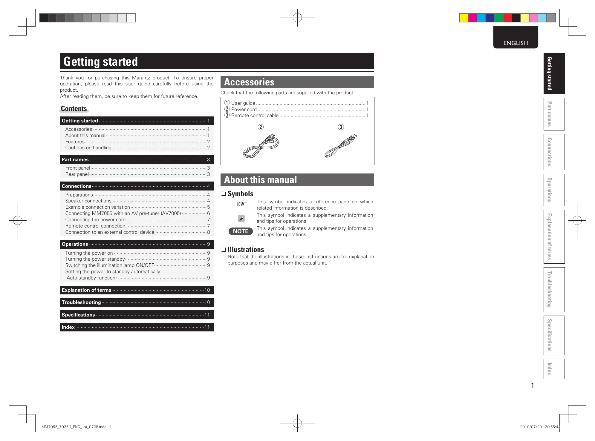
Wall Paroi Pared☐ CAUTIONS ON INSTALLATION PRÉCAUTIONS D'INSTALLATION EMPLAZAMIENTO DE LA INSTALACIÓN
* For proper heat dispersal, do not install this unit in a confined space, such as a bookcase or similar enclosure.
- More than 0.3m (12 in.) is recommended.
- Do not place any other equipment on this unit.
Thank you for purchasing this Marantz product. To ensure proper operation, please read this user guide carefully before using the product.
After reading them, be sure to keep them for future reference.
Contents
Getting started 1
Accessories 1
About this manual....1
Features 2
Cautions on handling 2
Part names....3
Front panel....3
Rear panel....3
Connections 4
Preparations....4
Speaker connections 4
Example connection variation....5
Connecting MM7055 with an AV pre-tuner (AV7005) 6
Connecting the power cord 7
Remote control connection 7
Connection to an external control device 8
Operations 9
Turning the power on 9
Turning the power standby....9
Switching the illumination lamp ON/OFF....9
Setting the power to standby automatically
(Auto standby function) 9
Explanation of terms 10
Troubleshooting....10
Specifications 11
Index 11
Accessories
Check that the following parts are supplied with the product.
① User guide....1
② Power cord .... 1
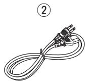
③ Remote control cable 1
About this manual
Symbols

This symbol indicates a reference page on which related information is described.

This symbol indicates a supplementary information and tips for operations.
NOTE
This symbol indicates a supplementary information and tips for operations.
□ Illustrations
Note that the illustrations in these instructions are for explanation purposes and may differ from the actual unit.
Features
Current feedback discrete power amp
This is equipped with a current feedback power amp that uses the complimentary push-pull circuit used in the SM-11S1 Marantz Hi-Fi power amp. This amp provides increased operating stability, and high-speed, wide ranging high-density playback.
The current/voltage conversion amplification section in the latter part of the power amp is equipped with a Wilson current mirror circuit that amplifies to the high sound range with low distortion.
Improved instant power supply capability
The final stage of the power amp is equipped with the same LAPT (high efficiency power transistor) that is installed in the SM-11S1 Marantz Hi-Fi power amp, providing improved instant power supply capability.
The power section is equipped with a large-sized transformer. As one of the essential parts of the power section, this unit is equipped with Marantz original 33,000 F / 71 V×2 (MM7055), and 15,000 F / 71 V×2 (MM7025) block condensers, which have been repeatedly tested for sound quality.
These improvements to the power supply capability provide a powerful, presence-filled sound.
High sound quality design based on pure surround philosophy
Equipped with a chimney-shaped heat sink to efficiently process the heat emitted from each channel amp, and exceptionally quiet cooling fans. A high-sensitivity temperature sensor IC is used to control the cooling fans, adjusting the rotation speed to match the amount of heat generated by the amp.
These components provide the sound quality and low-noise you would expect at a high-end theater.
In addition, this unit is designed for superb quality sound, and is equipped with high quality components such as a high-end audio condenser and film condenser throughout.
BALANCED/UNBALANCED selecting function
Depending on the desired use, input for each channel can be selected between BALANCED input and UNBALANCED input.
Remote Power Control
This unit is equipped with a remote power control function. When a Marantz AV Pretuner AV8003 or AV7005 is connected to this unit, this unit's power can be switched ON/OFF together with the AV8003 or AV7005 power supply.
Connection to the AV8003 or AV7005 is a ground floating connection that prevents negative influences on sound quality as far as possible.
Other Functions
Equipped with IR flash input that supports custom installations, and DC trigger input and output terminals.
Cautions on handling
- Before turning the power switch on
Check once again that all connections are correct and that there are no problems with the connection cables.
- Power is supplied to some of the circuitry even when the unit is set to the standby mode. When going on vacation or leaving home for long periods of time, be sure to unplug the power cord from the power outlet.
- About condensation
If there is a major difference in temperature between the inside of the unit and the surroundings, condensation (dew) may form on the operating parts inside the unit, causing the unit not to operate properly.
If this happens, let the unit sit for an hour or two with the power turned off and wait until there is little difference in temperature before using the unit.
- Cautions on using mobile phones
Using a mobile phone near this unit may result in noise. If that occurs, move the mobile phone away from this unit when it is in use.
- Moving the unit
Turn off the power and unplug the power cord from the power outlet. Next, disconnect the connection cables to other system units before moving the unit.
- About Care
- Wipe the cabinet and control panel clean with a soft cloth.
- Follow the instructions when using a chemical cleaner.
- Benzene, paint thinner or other organic solvents as well as insecticide may cause material changes and discoloration if brought into contact with the unit, and should therefore not be used.
Part names
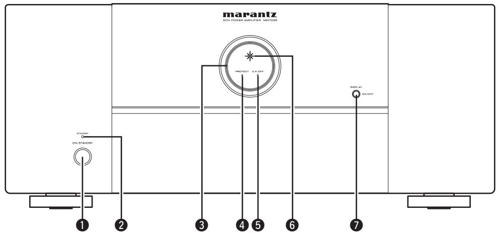
Front panel
For buttons not explained here, see the page indicated in parentheses ( ).
MM7055
text_image
marantz SOL POWER AMPLIFUS-50V/50A PROJECT A.P.OFF SPOLAY ON/OFF ON/STANCEY 1 2 3 4 5 6 7MM7025
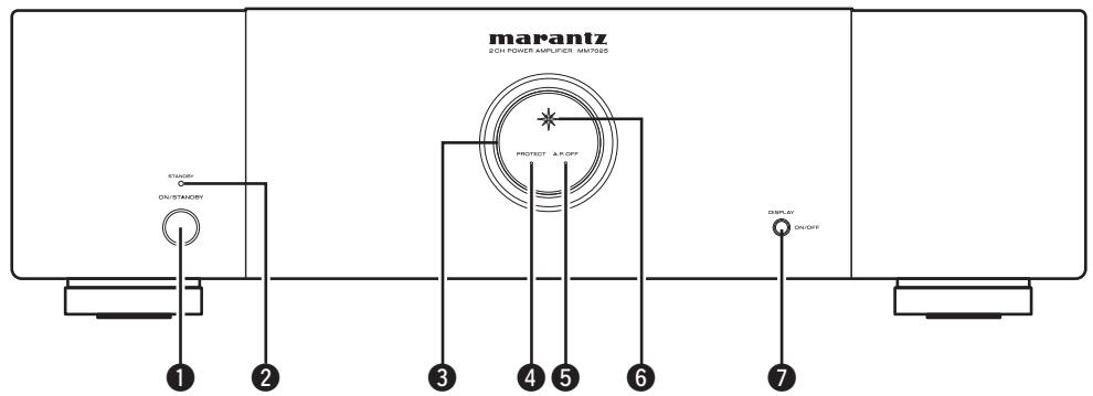
text_image
marantz 2 OH POWER AMPLIFIER MM7025 STANDARD ON/STANDARD PROTECT A/R-OFF DISPLAY ON/OFF 1 2 3 4 5 6 7① Power switch (ON/STANDBY) ...... (9)
② STANDBY indicator....(9)
③ Illumination lamp ...... (9)
4 Protection indicator (PROTECT)....(9, 10)
⑤ Auto power off indicator (A.P.OFF) ...... (9)
⑥ Power indicator …… (9)
⑦ DISPLAY button....(9)
- Press this button to turn the illumination lamp ON/OFF.
- You can set the auto standby function by pressing and holding this button for more than 5 seconds.
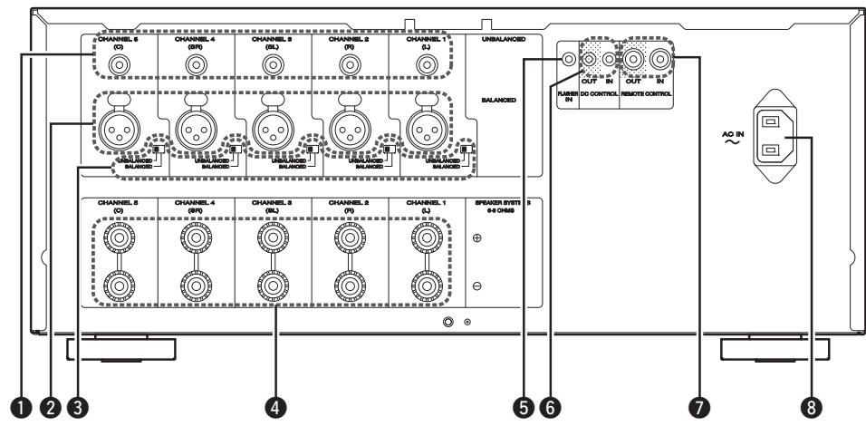
Rear panel
See the page indicated in parentheses ().
MM7055
text_image
CHANNEL 5 (C) CHANNEL 4 (SP) CHANNEL 3 (SL) CHANNEL 2 (P) CHANNEL 1 (L) UNBALANCED BALANCED CHANNEL 5 (C) CHANNEL 4 (SP) CHANNEL 3 (SL) CHANNEL 2 (P) CHANNEL 1 (L) SPENDER SYSTEM 5 + - - + OUTPUT IN DO CONTROL RUNNING IN OUT IN REMOTE CONTROL AO IN 1 2 3 4 5 6 7 8MM7025
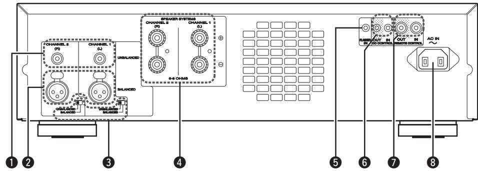
text_image
CHANNEL 2 CHANNEL 1 UNBALANCED S-6 CHUBS S-6 CHUBS CHANNEL 2 CHANNEL 1 S-6 CHUBS CHANNEL 2 CHANNEL 1 S-6 CHUBS CHANNEL 2 CHANNEL 1 S-6 CHUBS CHANNEL 2 CHANNEL 1 S-6 CHUBS CHANNEL 2 CHANNEL 1 S-6 CHUBS CHANNEL 2 CHANNEL 1 S-6 CHUBS CHANNEL 2 CHANNEL 1 S-6 CHUBS CHANNEL S- CHANNEL S- CHANNEL S- CHANNEL S- CHANNEL S- CHANNEL S- CHANNEL S- CHANNEL S- CHANNEL S- CHANNEL S- CHANNEL S- CHANNEL S- CHANNEL S- CHANNEL S- CHANNEL S- CHANNEL S- CHANNEL S- CHANNEL S- CHANNEL S- CHANNEL S- CHANNEL S- CHANNEL S- CHANNEL S- CHANNEL S- CHANNEL S- CHANNEL S- CHANNEL S- CHANNEL S- CHANNEL S- CHANNEL S- CHANNEL S- CHANNEL S- CHANNEL S- CHANNEL S- illegal illegal illegal illegal illegal illegal illegal illegal illegal illegal illegal illegal illegal illegal illegal illegal illegal illegal illegal illegal illegal illegal illegal illegal illegal illegal illegal illegal illegal illegal illegal illegal illegal illegal illegal illegal illegal illegal illegal illegal illegal illegal illegal illegal illegal illegal illegal illegal illegal illegal illegal① RCA input connectors (UNBALANCED) …… (6)
② XLR input connectors (BALANCED) ...... (6)
③ Input selector....(4)
4 Speaker terminals (SPEAKER SYSTEMS) ...... (6)
⑤ Flasher input terminals (FLASHER IN) ...... (8)
⑥ DC CONTROL jacks ...... (8)
⑦ REMOTE CONTROL connectors …… (7, 8)
⑧ AC inlet (AC IN)......(7)
Connections
NOTE
- Do not plug in the power cord until all connections have been completed.
- When making connections, also refer to the operating instructions of the other components being connected.
- Check the channel, and then connect correctly.
- Do not bundle power cords together with connection cables. Doing so can result in noise.
Preparations
Cables used for connections
Prepare the correct cables for use with the additional devices.
| Audio cables | |
| Balanced connections (XLR) |  |
| Unbalanced connections (RCA) | 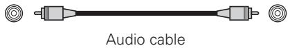 |
| Speaker connections | 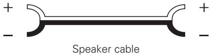 |
Audio cables
Sets the connected input connectors
Switches the input settings used for input to each channel.

BALANCED: Set when connected to the XLR connector. UNBALANCED: Set when connected to the RCA connector.
NOTE
If audio is input into input connectors that are not set using the input switching switch, the audio will not be output from the speakers.
☐ XLR connector PIN arrangement
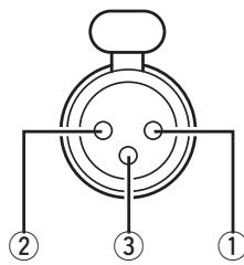
text_image
① ② ③The PIN arrangement in this device uses the European method. In the USA method, ② is COLD, and ③ is HOT.
When connecting a device that utilizes the USA type of PIN arrangement, replace the ② and ③ plugs on one side of the balanced cable.
NOTE
Do not short the HOT and GND or COLD and GND for use.
① GND (Ground)
② HOT (Hot)
③ COLD (Cold)
Speaker connections
Carefully check the channels of the speakers to be connected to this unit (L/R/SL/SR/C) and + (red), - (black), and connect like poles together.
Connecting the speaker cables
Peel off about 10 mm of sheathing from the tip of the speaker cable, then either twist the core wire tightly or terminate it.
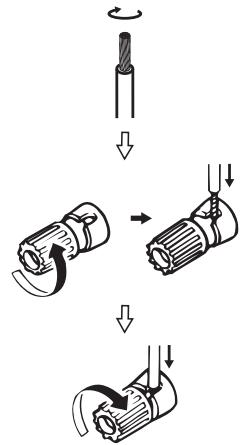
text_image
Diagram illustrating three-step mechanical assembly steps with arrows indicating direction of motionNOTE
- Connect so that the speaker cable core wires do not protrude from the speaker terminal. The protection circuit may be activated if the core wires touch the rear panel or if the + and - sides touch each other (page 10 "Protection circuit").
- Never touch the speaker terminals while the power supply is connected. Doing so could result in electric shock.
- Use speakers with impedance of 6 ohms or more.
Example connection variation
☐ Connection to an AV pre-tuner
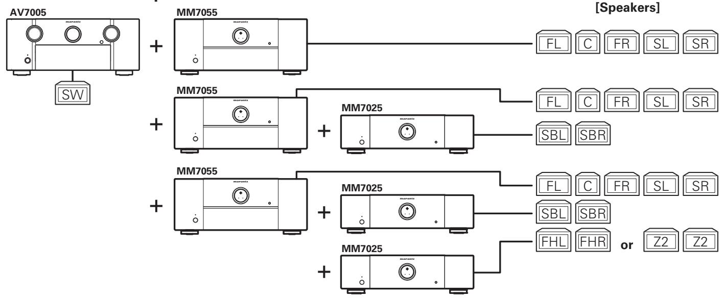
flowchart
graph TD
    A["AV7005"] --> B["SW"]
    C["MM7055"] --> D["FL C FR SL SR"]
    E["MM7055"] --> F["FL C FR SL SR"]
    G["MM7025"] --> H["SBL SBR"]
    I["MM7055"] --> J["FL C FR SL SR"]
    K["MM7025"] --> L["SBL SBR"]
    M["MM7025"] --> N["FHL FHR or Z2 Z2"]

5.1ch surround playback

7.1ch surround playback

9.1ch surround playback or
7.1ch surround playback + ZONE2 playback
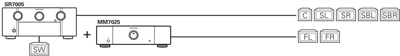
☐ Connection to an AV receiver
Using both the AV receiver and the amplifier of this unit. Combine with an AV receiver that has a pre-out output.
flowchart
graph LR
    A["SR7005"] --> B["+"]
    C["MM7025"] --> B
    D["SW"] --> A
    E["C"] --> F["SL"]
    G["SR"] --> H["SBL"]
    I["SBR"] --> J["FL"]
    K["FR"] --> L["FL"]

Front speaker upgrade
☐ Connection to a 2ch pre-amp

text_image
MM7025 FL FR
2ch playback
FL Front speaker (L)
FR Front speaker (R)
Z2 Zone2 speaker
C Center speaker
SW Subwoofer
SL Surround speaker (L)
SR Surround speaker (R)
SBL Surround back speaker (L)
SBR Surround back speaker (R)
FHL Front height speaker (L)
FHR Front height speaker (R)
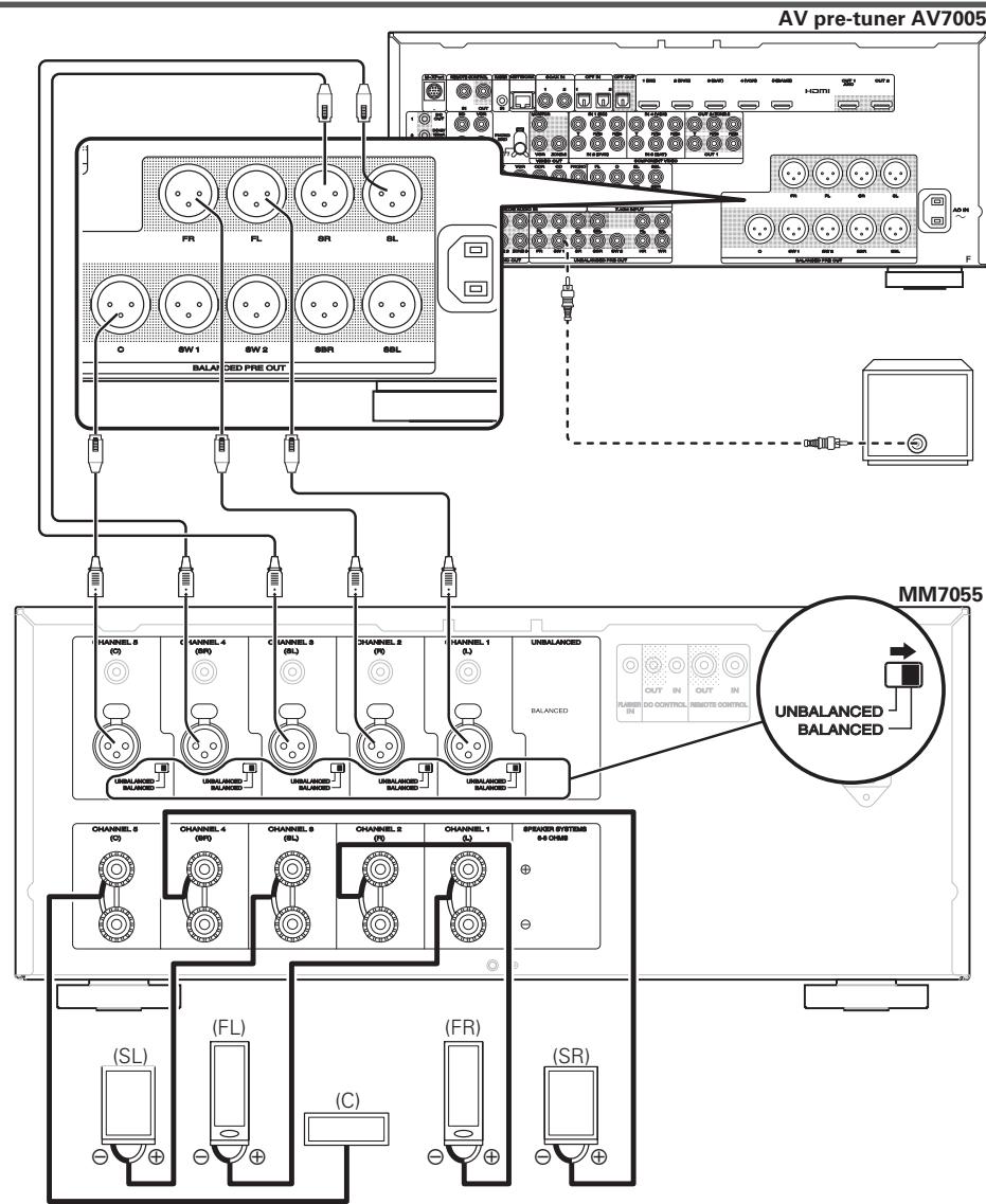
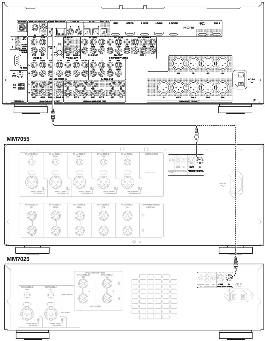
Connecting MM7055 with an AV pre-tuner (AV7005)
The illustrations below show connection examples for performing 5.1-channel surround playback using the MM7055 and AV pre-tuner (AV7005).

- For settings and operating procedures of the AV7005, see the AV7005 instruction manual.
- When connecting the AV7005, be sure to also consult the AV7005 instruction manual.
Balanced connections
(when connecting to the XLR input connectors)
text_image
AV pre-tuner AV7005 FR FL SR SL O SW 1 SW 2 SSR SSL BALA DED PRE OUT HANNEIL 8 (C) CHANNEL 4 (BW) CHANNEL 9 (BL) CHANNEL 2 (P0) CHANNEL 1 (L) UNBALANCED BALANCED GOLDEN BALANCED CHANNEL 6 (C) CHANNEL 4 (BW) CHANNEL 9 (BL) CHANNEL 2 (P0) CHANNEL 1 (L) SPXEDER SYSTEMS #4 CHAB (SL) (FL) (C) (FR) (SR) MM7055 OUT IN OUT IN RUNBBER IN DO CONTROL REMOTE CONTROL UNBALANCED BALANCEDUnbalanced connections
(when connecting to the RCA input connectors)
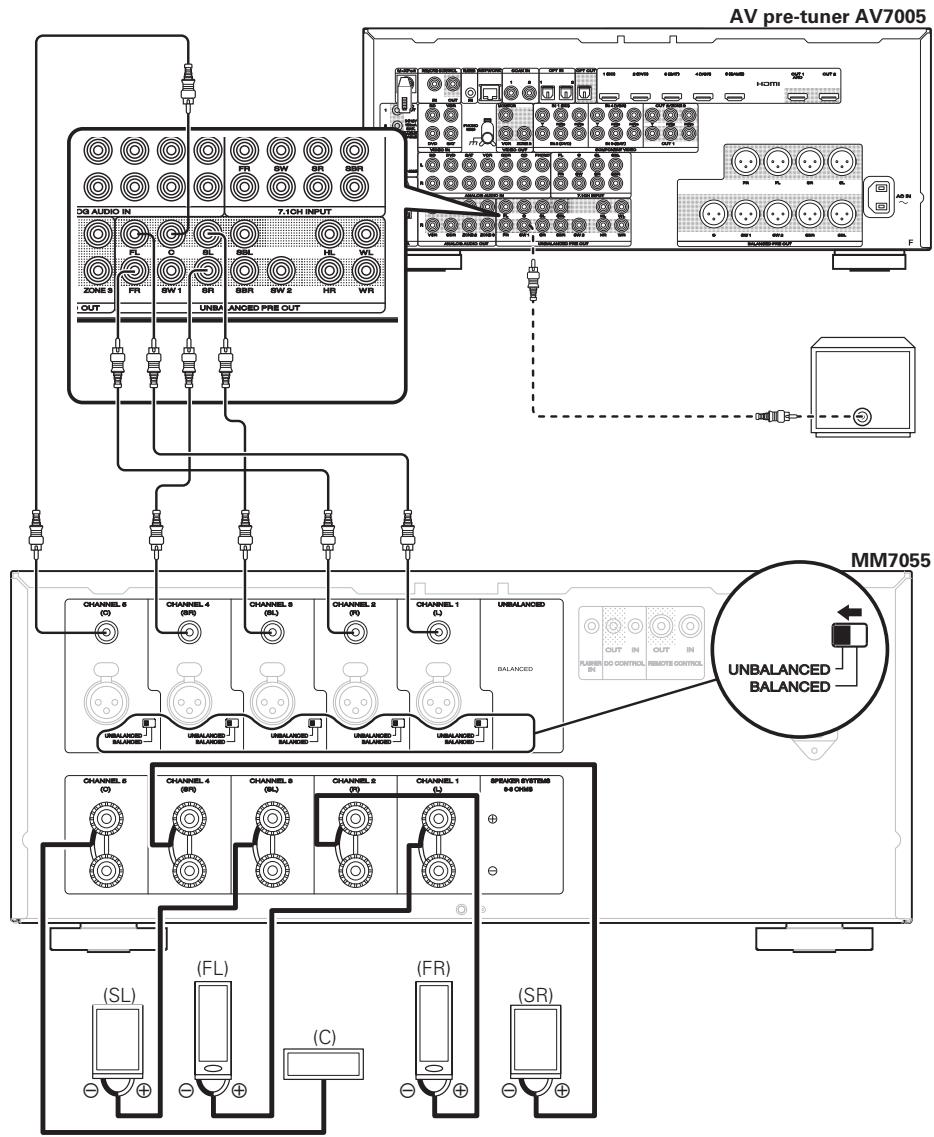
flowchart
graph TD
    subgraph_AV_pre_tuner_AV7005["AV pre-tuner AV7005"]
        direction TB
        A["AV pre-tuner AV7005"] --> B["AV pre-tuner AV7005"]
        B --> C["MM7055"]
    end

    subgraph_MM7055["MM7055"]
        direction LR
        D["MM7055"] --> E["AV pre-tuner AV7005"]
        E --> F["AV pre-tuner AV7005"]
        F --> G["AV pre-tuner AV7005"]
        G --> H["AV pre-tuner AV7005"]
        H --> I["AV pre-tuner AV7005"]

    subgraph MM7055_MM7055
        direction LR
        J["MM7055"] --> K["AV pre-tuner AV7005"]
        K --> L["AV pre-tuner AV7005"]
        L --> M["AV pre-tuner AV7005"]
        M --> N["AV pre-tuner AV7005"]

    end

    subgraph MM7055_MM7055
        direction LR
        O["MM7055"] --> P["AV pre-tuner AV7005"]
        P --> Q["AV pre-tuner AV7005"]
        Q --> R["AV pre-tuner AV7005"]
        R --> S["AV pre-tuner AV7005"]

    end

    subgraph MM7055_MM7055
        direction LR
        T["MM7055"] --> U["AV pre-tuner AV7005"]
        U --> V["AV pre-tuner AV7005"]
        V --> W["AV pre-tuner AV7005"]
        W --> X["AV pre-tuner AV7005"]

    end

    subgraph MM7055_MM7055
        direction LR
        Y["MM7055"] --> Z["AV pre-tuner AV7005"]
        Z --> AA["AV pre-tuner AV7005"]
        AA --> AB["AV pre-tuner AV7005"]
        AB --> AC["AV pre-tuner AV7005"]

    end

    subgraph MM7055_MM7055
        direction LR
        AD["MM7055"] --> AE["AV pre-tuner AV7005"]
        AE --> AF["AV pre-tuner AV7005"]
        AF --> AG["AV pre-tuner AV7005"]

    end

    subgraph MM7055_MM7055
        direction LR
        AF1["MM7055"] --> AG1["AV pre-tuner AV7005"]
        AG1 --> AH["AV pre-tuner AV7005"]

    end
Connecting the power cord
Wait until all connections have been completed before connecting the power cord.
MM7055

text_image
To household power outlet (AC 120 V, 60 Hz) Power cord (supplied)MM7025
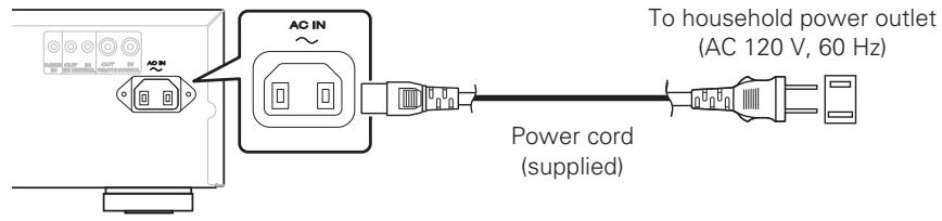
text_image
AC IN To household power outlet (AC 120 V, 60 Hz) Power cord (supplied)NOTE
- Insert the plugs securely. Loose connections will result in the generation of noise.
- During power standby, a minimal amount of power is consumed. To totally cut off the power, remove the power cord from the power outlet.
Remote control connection
When connecting a Marantz AV8003 or AV7005 AV pre-tuner, you can switch the power of this unit to ON/STANDBY together with the AV8003/AV7005 power supply.
For details, see the AV8003 or AV7005 instruction manual.
text_image
MM7055 MM7025Connection to an external control device
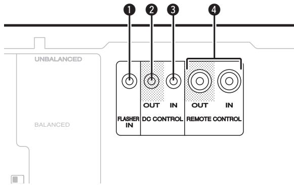
text_image
UNBALANCED BALANCED 1 2 3 4 FLASHER IN OUT IN DC CONTROL OUT IN REMOTE CONTROL1 Flasher input connector (FLASHER IN)
Used when connecting a control box or other control device to this unit, and using such a device to control this unit.
② DC control output connector (DC CONTROL OUT)
Used when connecting a device that has a DC control input terminal to this unit, and linking the power ON/STANDBY function of this device with the power ON/STANDBY of the connected device.
An electrical signal of max 12 V/44 mA is output from the DC control output terminal.
For details, see the instruction manual of the connected device.
NOTE
Do not use the DC control output terminal as the power supply for an external device.
③ DC control input connector (DC CONTROL IN)
Used when connecting a unit that has a DC control input terminal to this device, and linking the power ON/STANDBY of the connected device with the power ON/STANDBY of this unit.
For details, see the instruction manual of the connected device.
NOTE
When a 5 V – 15 V voltage is input to the DC control input terminal, the power of this unit switches ON.
However, inputting voltage outside of this range will cause damage to this unit.
4 Remote control connector
Used when connecting an external control device to this unit, and using the device to control this unit.
NOTE
When connecting a Marantz AV8003 or AV7005 AV pre-tuner, you can switch the power of this unit to ON/STANDBY together with the AV8003/AV7005 power supply.
For details, see the AV8003 or AV7005 instruction manual.
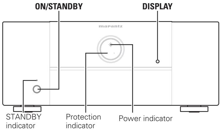
Operations
MM7055
text_image
ON/STANDBY DISPLAY marantz STANDBY indicator Protection indicator Power indicatorMM7025
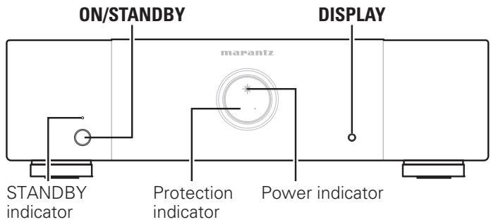
text_image
ON/STANDBY DISPLAY marantz STANDBY indicator Protection indicator Power indicatorTurning the power on
When the power is in standby, press ON/STANDBY.
- The protection indicator flashes for approximately 7 seconds, and the power switches on.
• The power indicator lights.
NOTE
When turning the power ON, turn the volume control of connected devices down to the minimum.
Turning the power standby
When the power is in power on, press ON/STANDBY.
The STANDBY indicator lights, and the power changes to standby.
NOTE
Even if the unit is switched to standby, some of the circuits are still active. If you will not be using this unit for a prolonged period (due to a holiday etc), remove the power plug from the wall socket.
Furthermore, to prevent unexpected accidents, make sure the power plug is located where it can be removed at any time.
Switching the illumination lamp ON/OFF
If the unit is being used with the factory settings, the illumination lamp lights.
You can turn the illumination lamp off if it is making the room too bright at nighttime.
Press DISPLAY.
Each time this button is pressed, the illumination lamp turns ON/OFF.
Setting the power to standby automatically (Auto standby function)
When the auto standby function is set to ON, if there are no signals input into this unit and no operations are performed for more than 30 minutes, the power of this unit automatically switches to standby.
- The factory setting is "Off".
Press DISPLAY for more than 5 seconds.
The auto power off display switches as shown below according to the auto standby function.
- When the auto standby function is ON: Lit
- When the auto standby function is OFF: Off
Explanation of terms
P
Protection circuit
This is a function to prevent damage to components within the power supply when an abnormality such as an overload or excess voltage occurs for any reason.
In this unit, the STANDBY indicator and protection indicator blinks and the unit enters standby mode when an abnormality occurs.
S
Speaker impedance
This is certain-rated resistance of the speaker set to an alternating current and expressed in ohms.
The smaller the impedance, the greater the output.
However, load on the amplifier is increased. Use speakers whose impedance is supported by this unit.
Troubleshooting
If a problem should arise, first check the following:
- Are the connections correct?
- Is the set being operated as described in the user guide?
- Are the other components operating properly?
If this unit does not operate properly, check the items listed in the table below. Should the problem persist, there may be a malfunction. In this case, disconnect the power immediately and contact your store of purchase.
| Symptom | Cause/Solution | Page |
| The power does not switch on.Or, the power switches off immediately after being switched on. | Check that the power plug is inserted correctly in the wall socket.The protective circuit has operated. In this case, remove the power plug from the wall socket, and wait for at least 1 minute before inserting it in the wall socket again. | 77, 10 |
| There is no sound from the speakers. | Check the speaker connections and connections to the other devices.Alter the input selector to match the input connector (BALANCED or UNBALANCED) of the connected device. | 64 |
| The power suddenly switches off during use, and the STANDBY indicator and protection indicator flash at approximately 0.5 second intervals. | The internal temperature of the unit has increased, causing the protective circuit to operate. Remove the power plug from the wall socket, wait until the temperature of the unit has dropped adequately, and then insert the power plug back into the wall socket.Install this unit in a well-ventilated location.Use speakers that have the specified impedance.If the two core wires of the speaker cables are touching, or if a core wire is out of the terminal causing the core wire to touch the rear panel of this unit, the protective circuit will operate. Remove the power plug from the wall socket, and firmly re-insert the core wire, or fix the terminal before reconnecting it.Turn the volume down on the amp connected to this unit, and insert the power plug again. | --------44, 10-- |
| When the power switches off suddenly during use, the STANDBY indicator flash at approximately 0.1 second intervals and protection indicator flash at approximately 0.5 second intervals. | The protective circuit has operated. In this case, remove the power plug from the wall socket, re-examine the installation conditions of this unit, and check the speaker cable connections. If the same situation occurs when the power is switched on again, contact the Marantz Service Center. | 6, 7, 10 |
Specifications
MM7055
Rated power output 140 W/ch, 8 Ω
(from 20 Hz to 20 kHz/THD = 0.08 %, 170 W/ch, 6 Ω two channels driven):
Maximum effective output power 210 W/ch, 6 Ω
(from 1 kHz, two channels driven):
Output bandwidth (8 Ω load, 0.09 %): 5 Hz – 40 kHz
Frequency response (1 W, 8 Ω): 8 Hz – 100 kHz (±3 dB)
Damping factor: 100
Input sensitivity/impedance: 1.2 V / 22 kΩ (UNBALANCED)
2.4 V / 30 kΩ (BALANCED)
Signal-to-noise ratio (IHF-A): 105 dB
Voltage amplifi cation level: 29 dB
Supply voltage: AC 120 V, 60 Hz
Power consumption: 660 W
Standby power: 0.2 W
Maximum external dimensions: 440 (W) x 183 (H) x 384 (D) mm
Weight: 15.7 kg
MM7025
Rated power output 140 W/ch, 8 Ω
(from 20 Hz to 20 kHz, two channels driven): 170 W/ch, 6 Ω
Maximum effective output power 210 W/ch, 6 Ω
(from 1 kHz, two channels driven):
Output bandwidth (8 Ω load, 0.09 %): 5 Hz – 40 kHz
Frequency response (1 W, 8 Ω): 8 Hz – 100 kHz (±3 dB)
Damping factor: 100
Input sensitivity/impedance: 1.2 V / 22 kΩ (UNBALANCED)
2.4 V / 30 kΩ (BALANCED)
Signal-to-noise ratio (IHF-A): 105 dB
Voltage amplifi cation level: 29 dB
Supply voltage: AC 120 V, 60 Hz
Power consumption: 330 W
Standby power: 0.2 W
Maximum external dimensions: 440 (W) x 126 (H) x 352 (D) mm
Weight: 10.8 kg
For purposes of improvement, specifications and design are subject to change without notice.
Index

Numerics
2ch playback 5
5.1ch surround playback 5
7.1ch surround playback 5
9.1ch surround playback 5


Accessories 1
Audio cable 4
Auto standby function 9


Balanced cable 4


Condensation 2
Connection
Power cord....7
Connections
Balanced 6
External control device 8
Power cord....7
Remote control 7
Unbalanced 6


Example connection variation 5


For expanding to front height speakers or front
wide speakers 5
Front panel 3
Front speaker upgrade 5


Protection circuit 10


Rear panel 3


Speaker cable 4
Speaker impedance....10
Switches the connected input connectors....4
Switching the illumination lamp ON/OFF 9


Troubleshooting 10
Turning the Power On 9
Turning the power standby 9


XLR connector PIN arrangement 4
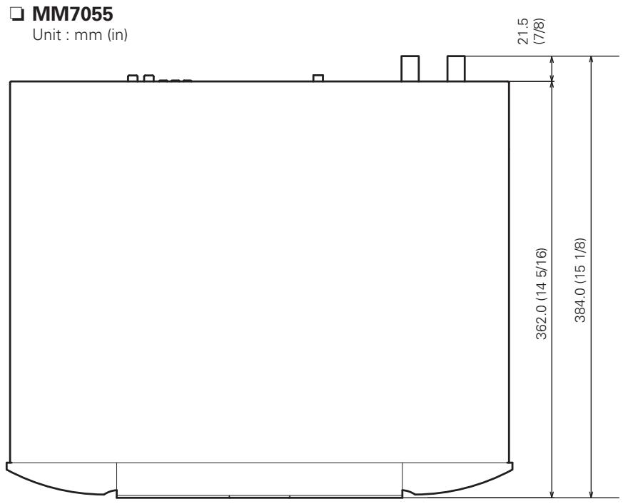
text_image
MM7055 Unit : mm (in) 21.5 (7/8) 362.0 (14 5/16) 384.0 (15 1/8)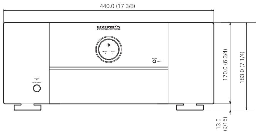
text_image
440.0 (17 3/8) DYNEPTOMY ELECTRODES & SOLUTIONS 170.0 (6 3/4) 183.0 (7 1/4) 13.0 (9/16)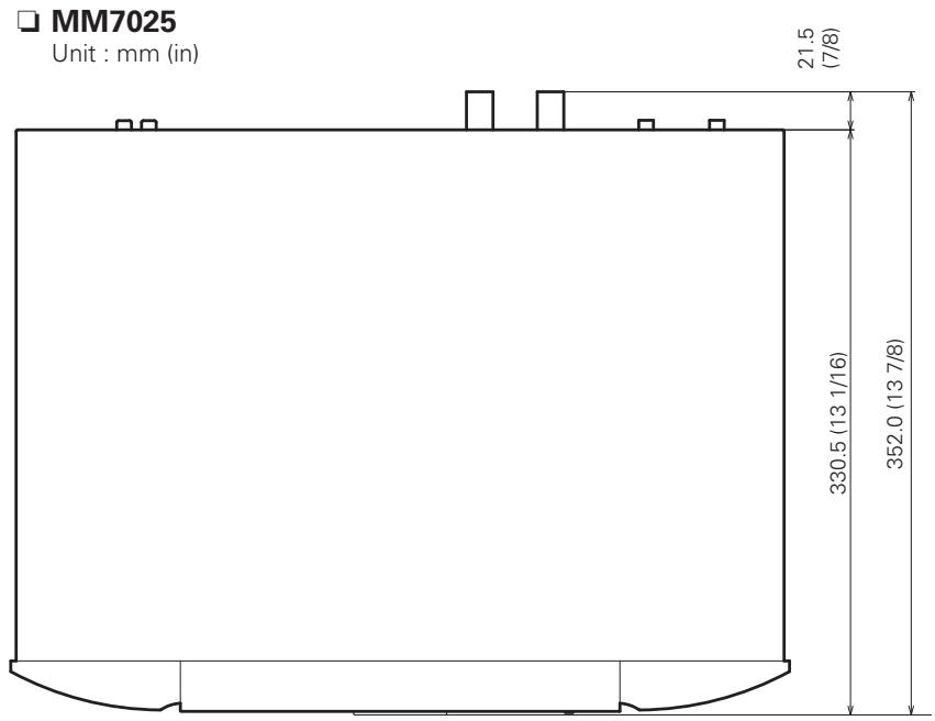
text_image
MM7025 Unit : mm (in) 21.5 (7/8) 330.5 (13 1/16) 352.0 (13 7/8)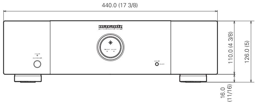
text_image
440.0 (17 3/8) Transatlantic 110.0 (4 3/8) 126.0 (5) 16.0 (11/16)www.marantz.com
You can find your nearest authorized distributor or dealer on our website.
marantz ^® is a registered trademark.