RIVA 2 - Electric heating THERMOR - Free user manual and instructions
Find the device manual for free RIVA 2 THERMOR in PDF.
User questions about RIVA 2 THERMOR
0 question about this device. Answer the ones you know or ask your own.
Ask a new question about this device
Download the instructions for your Electric heating in PDF format for free! Find your manual RIVA 2 - THERMOR and take your electronic device back in hand. On this page are published all the documents necessary for the use of your device. RIVA 2 by THERMOR.
USER MANUAL RIVA 2 THERMOR
natural_image
Interior scene with a white horizontal heater mounted on a wall, next to a stone wall and a potted plant (no visible text or symbols)RADIATEUR SÈCHE-SERVIETTES
ELECTRONIC RADIATOR - TOWEL RAIL
ELEKTRONISCHER HANDTUCHTROCKNER
ELEKTRONISCHE RADIATOR
VOOR HANDDOCKEN
RADIADOR SECA TOALLAS
RADIADOR SECO-TOALHAS
Riva 2
RADIATEUR SÈCHE-SERVIETTES
ELECTRONIC RADIATOR - TOWEL RAIL
ELEKTRONISCHER HANDTUCHTROCKNER
ELEKTRONISCHE RADIATOR VOOR HANDDOCKEN
RADIADOR SECA TOALLAS
RADIADOR SECO-TOALHAS
natural_image
Close-up of white PVC ladder structure against a blurred background (no text or symbols visible)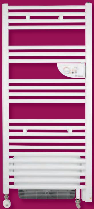
natural_image
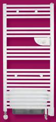
White horizontal heater rack against a magenta background, no text or symbols visiblenatural_image
Close-up of a white heating water heater with control dial and indicator lights (no visible text or symbols)Riva 2
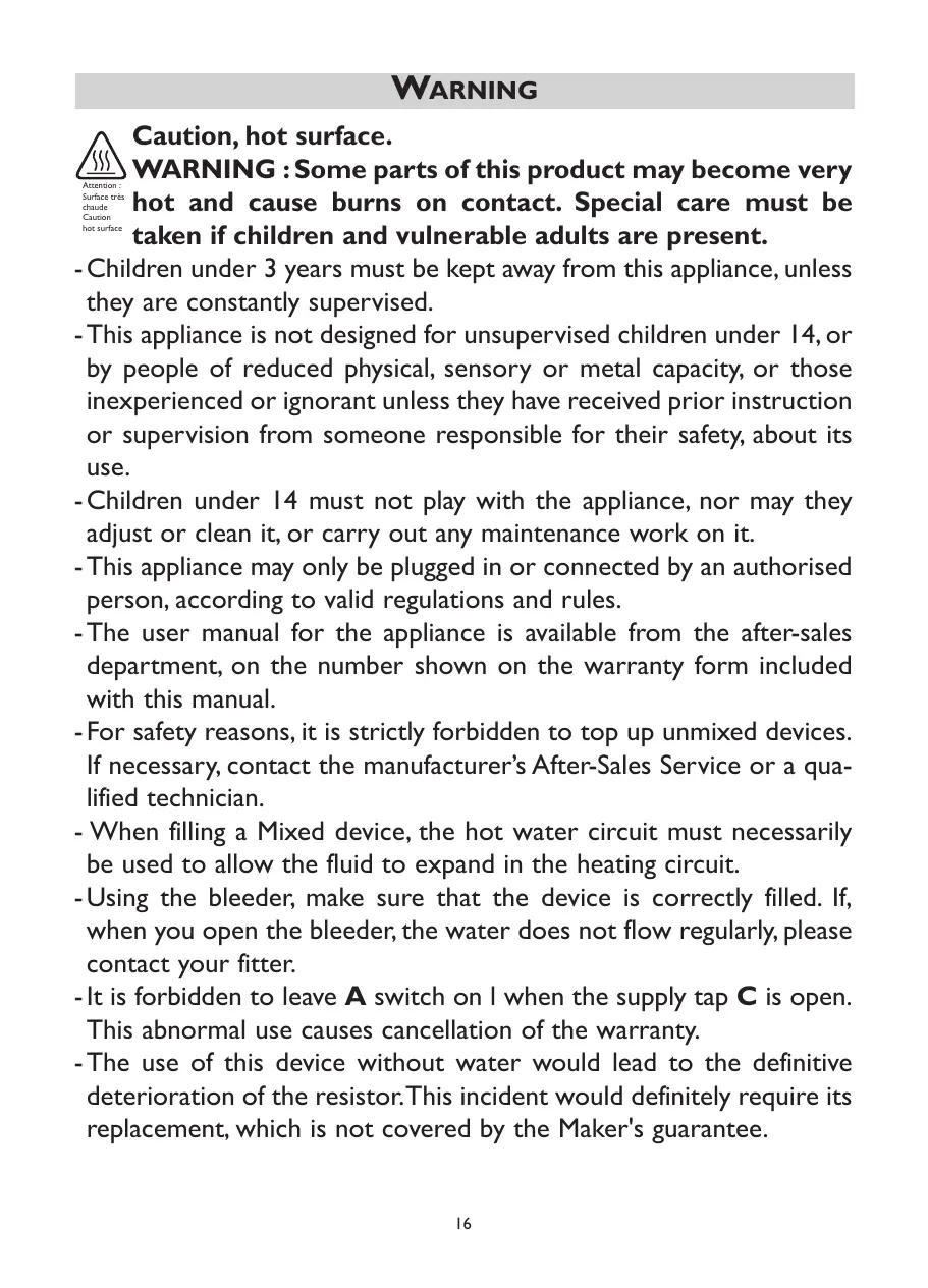
Caution, hot surface.
WARNING : Some parts of this product may become very hot and cause burns on contact. Special care must be taken if children and vulnerable adults are present.
- Children under 3 years must be kept away from this appliance, unless they are constantly supervised.
- This appliance is not designed for unsupervised children under 14, or by people of reduced physical, sensory or metal capacity, or those inexperienced or ignorant unless they have received prior instruction or supervision from someone responsible for their safety, about its use.
-Children under 14 must not play with the appliance, nor may they adjust or clean it, or carry out any maintenance work on it. - This appliance may only be plugged in or connected by an authorised person, according to valid regulations and rules.
- The user manual for the appliance is available from the after-sales department, on the number shown on the warranty form included with this manual.
- For safety reasons, it is strictly forbidden to top up unmixed devices. If necessary, contact the manufacturer's After-Sales Service or a qualified technician.
- When filling a Mixed device, the hot water circuit must necessarily be used to allow the fluid to expand in the heating circuit.
- Using the bleeder, make sure that the device is correctly filled. If, when you open the bleeder, the water does not flow regularly, please contact your fitter.
- It is forbidden to leave A switch on I when the supply tap C is open. This abnormal use causes cancellation of the warranty.
- The use of this device without water would lead to the definitive deterioration of the resistor. This incident would definitely require its replacement, which is not covered by the Maker's guarantee.
- The boiler return tap D must obligatorily remain open, even in the case of the SUMMER SETTING in order to allow expansion of the fluid in the circuit so as to avoid any damage to the device.
 | Appliance carrying this symbol must never be disposed of with household waste, but must be collected separately for recycling. At the end of their life, products must be collected and recycled according to local regulations and ordinances. |
 | When an appliance is installed at a higher altitude, the air output temperature rises (around 10^ C per 1000 m rise in ground). |
The device you have just purchased was submitted to many tests and checks ensuring its quality. We thank you for your choice and trust. We hope you will be fully satisfied.
A few recommendations:
Read the instructions before installing the device.
Power the device off before intervening on it, and check the power supply voltage.
Store the instructions, even after installing the device.
INSTALLING THE DEVICE
I) Location of the device
- This device was designed to be installed in residential premises. In any other case, please call your distributor.
- Installation must comply with the standards currently enforced in the country of use.
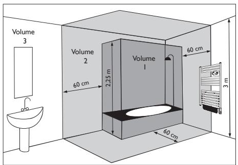
- Locate the heater within minimum distances from obstacles. Do not install the device :
- In a draft likely to affect its control (under centralised mechanical ventilation, etc...).
• Under a fixed mains outlet. - Inside zones 0 and 1 in bathrooms.
The device is to be installed so that switches and other controls cannot be touched by a person in the bath or shower, except in the UK where IEE Regulations 701.512.2 and 701.512.3 apply. These allow the use of IP24 rated products and their integral controls in Zone 2 and outside zones.
text_image
Volume 3 Volume 2 60 cm Volume 1 60 cm 3 m 60 cm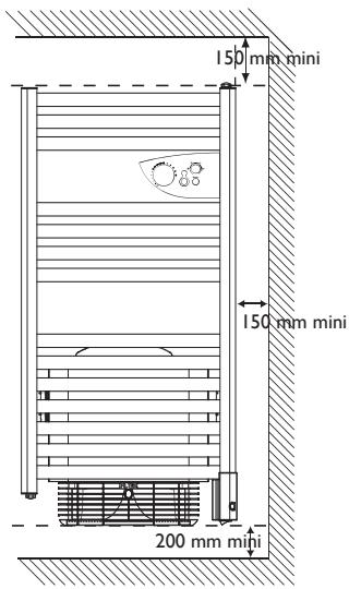
2) How to install the device
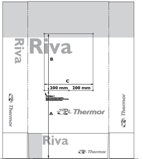
The installation template is printed on the packaging.
I/ Unfasten the carton's flaps and place it against the wall with the lower flap folded back and resting flat on he floor. Prick out the four drill holes though the packaging (without drilling) and then remove the packaging.
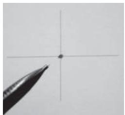
2/ Carefully mark the drilling points with a pencil (draw a cross, 2 cm wide).
3/ Drill the holes.
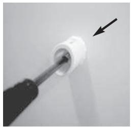
4/ Screw on and orient the sleeve in place. Fit the screws with the washers provided.
5/ Screw the pins on the tubes without locking them. Check they are correctly positioned by inserting them in the sleeves, with the device. After finding the right position, tighten the screws on each pin.
6/ Place the device on the wall, in the sleeves. Tighten all the locking screws. Fit the caps on the ends of the pins.
text_image
Riva Thermor B C 200 mm 200 mm A Thermor Thermor Riva ThermorSOL
Note: The pins supplied with the device are of the standard type. In case of a particular stand, use appropriate pins.
natural_image
Close-up of a pencil tip pointing at a cross formed by intersecting lines (no text or symbols visible)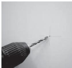
natural_image
Close-up of a drill bit with a screwdriver tip, showing the needle and center point (no text or symbols visible)| Measurement for fitting lugs (mm) | |||
| Power | A | B | C |
| 500 W | 320 mini | 656 | 400 |
| 750 W | 1066 | ||
| 1000 W | 1599 | ||
| 1500W | 525 mini | 451 | 386 |
| 1750W | 861 | ||
| 2000W | 1394 | ||
natural_image
Close-up of a white screwdriver tip with an arrow pointing to it, no visible text or symbols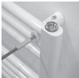
natural_image
Close-up of a white cylindrical mechanical component with a metal screw inserted, no visible text or symbols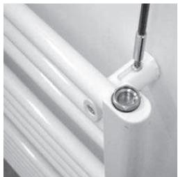
natural_image
Close-up of a white cylindrical mechanical component with a metallic fitting and a metal bracket, no visible text or symbols.3) Connecting the device
text_image
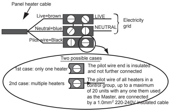
Panel heater cable Live=brown LIVE Neutral=blue NEUTRAL Pilot wire=Black Electricity grid Two possible cases 1st case: only one heater The pilot wire end is insulated and not further connected 2nd case: multiple heaters The pilot wire of all heaters in a control group, up to a maximum of 20 units with any one them used as the Master, are connected by a 1.0mm² 220-240V insulated cable- The device must be supplied with 230V, 50Hz.
- Mains connection must be ensured using the 3-wire cable factory fitte to the heater, through a connecting box. In damp premises, such as bathrooms and kitchens, install the connecting box at least 25cm from the ground..
- The installation must comply with local national regulation. If in doubt, ask the national Atlantic distributor.
- Ground connection is forbidden.
Do not connect the pilot wire (black) to ground.
- If power cable is damaged or too short, to avoid any danger it must be replaced by a qualified electrician using special tools.
- If a heater pilots or is piloted by a 30mA differential (e.g. bathroom), the pilot wire supply must be protected on this differential.
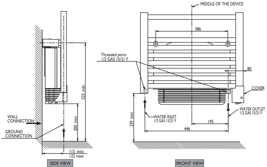
4) How to connect the mixed version to the water system?
For the connection of hot water, the mixed version comprises 2 threaded ports 1/2 gas 15/21 F situated at the base, as well as a purge with adjustable spray on the top on the right
Follow the flow direction as well as the figures stipulated on the diagram below.
text_image
WALL CONNECTION GROUND CONNECTION 115 mini 122 maxi SIDE VIEW 525 mini 200 mini Threaded ports 1/2 GAS 15/21 F MIDDLE OF THE DEVICE 386 80 COVER 259 mini WATER INLET 1/2 GAS 15/21 F 446 195 WATER OUTLET 1/2 GAS 15/21 F FRONT VIEW5) Programming
The device can be controlled remotely if its pilot wire is connected to a device fitted with a programmer, a programming unit or an energy management unit.
Chart indicating the orders the device can receive over its pilot wire
(to be measured between the pilot wire and the neutral).
| Orders received | Current absent | Full wave 230V | Negative half wave -115V | Positive half wave +115V |
| Ref/neutral oscilloscope |  |  |  | |
| Mode achieved | COMFORT | ECO | STANDBY | STOP HEATINGLOAD SHEDDING |
USING THE DEVICE
CASE OF THE MIXED VERSIONS WITH FAN
Description of the lower part of the device.
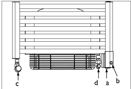
text_image
c d a bA Switch to control the heating resistor incorporated in the device.
B Indicator light to check the operating status of your device.
C Supply tap to allow inlet of hot water from the central heating. This can be thermostatically controlled or not depending on your choice.
D Boiler return tap to allow the hot water to leave the central heating.
Service pressure must not exceed 4 bar.
| Use on electricity SUMMER SETTINGThe central heating circuit is not working. | - A switch is on I.- The B indicator light is ON, the heating resistor incorporated in the device is supplied.- The supply tap C must be closed.- The boiler return tap D must remain open. |
| Use on central heating WINTER SETTINGThe central heating circuit is working. | - A switch is on O.- The B indicator light is OFF, the heating resistor incorporated in the device is not supplied.- The supply tap C must be open.- The boiler return tap D must remain open. |
USING THE DEVICE
Description of the control panel

text_image
① ② 1 h 2 h 3 4 5 6 7 Thermor① Temperature setting knob with Hors Gel position and ability to restrict the range.
② Time adjustment knob TURBO 1/4h, 1/2h, 1h, 2h.
③ Power On indicator
④ TURBO indicator
⑤ TURBO control
⑥ Heating ON/OFF switch
⑦ Heating indicator
Winter use with the boiler lit
Heating your room
- Increase or decrease the flow through the supply valve d, depending on the desired temperature (in the case of a thermostatic valve).
Use of Turbo mode
- Press switch ⑥, indicator light ③ illuminates.
- Set knob ① to ✧.
- Set Turbo mode's duration by turning knob ②.
- Press the same knob ② to start the Turbo. The “Turbo ON” ④ light illuminates. The fan operates for the selected period.
Use on electricity for versions:
- All electric with or without fan.
- Mixed with fan in SUMMER position.
Setting the CONFORT temperature
It is the temperature desired when the room is occupied.
a) Set the switch to ⑥ to the ON position, the ③ indicator lights.
b) Align the toothed screw ① with the marking 📄: the indicator light ⑦ illuminates if the temperature is less than desired.
Wait a few hours for the temperature to stabilise.
If the temperature setting does not suit you, adjust it using the adjusting screw ① Proceed step-by-step using the notches (one notch at a time).
The thermostat's cycle takes several minutes. It is possible that the heating indicator may not react instantaneously, but instead only on the next thermostat cycle.
Standby (Hors Gel) Mode

It is the mode enabling to maintain a temperature of approximately 7^ C in the room in case of prolonged absence from the house.
a) Leave switch ⑥ on the Marche position.
b) Set the knob 1 to ✱.
Turbo mode
It is the mode enabling to set the device into Forced Operation, ensuring prompt temperature increase in the room over the time defined (maximum power for conventional models and fan activation point for models with ventilating fan).
a) Leave the switch ⑥ on the Marche position.
b) Select the time for the Turbo using the knob ②.
c) Press the command ⑤, the indicators ④ and ⑦ light.
d) The TURBO mode can be interrupted manually before the end of the time set. In order to do this, press the command 5 again.
NB: For piloted devices, only the heating stop and frost setting instructions are prioritised when TURBO mode is activated (the other instructions are inoperative).
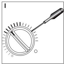
Locking commands
It is possible to lock the knob ① or restrict its use, preventing untimely handling of the device (children...).
natural_image
Diagram of a dial indicator with a screwdriver, showing measurement scale and pointer (no text or symbols)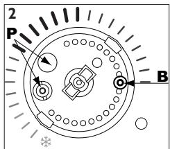
text_image
2 P B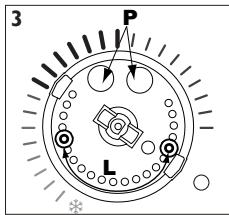
text_image
3 P LLocking the knob:
a) Set the knob to the position required.
b) Using a small-size flat-blade screwdriver, pull the knob's cap (1).
c) Detach pin P from its stand using a cutting tool.
d) Set pin P in the alignment of arrow B (2).
e) Refit the cap.
Limitation of the knob's use range:
a) Using a small-size flat-blade screwdriver, pull the knob's cap (1).
b) Remove the two P pins from their stand using a cutting tool.
c) Position the two P pins at each end of the operating range desired (3).
d) Refit the cap.
RECOMMENDATIONS OF USE
| When ventilating the room | Stop the heating by setting the switch to the Arrêt position. |
| If you live for less than 24 hours | Lower the temperature. |
| If you live for more than 24 hours or during summer | Set the temperature knob to ✝. |
IN CASE OF PROBLEM
| Problem | Check |
| The device does not heat | - Check that the premise circuit breakers are triggered or that the shedder (if you have one) has not interrupted the device's power supply.- Check the air temperature in the room.- Switch the heating off, then back on (6 switch):If the 7 indicator blinks 3 times: the measurement probe is damaged. Call your electrician to ensure its replacement.If the 7 indicator blinks 5 times: power surge in device supply. Power off the device (fuse, circuit breaker...), and call your electrician. |
| The heating device heats constantly | - Check that the device is not located in a draft or that the temperature setting has not been altered. |
| The last elements top and bottom are cooler than the rest of the device | - At the top, the upper elements are not completely filled to allow for expansion of the thermodynamic fluid. They heat up only by conduction.- At the bottom, the elements convey the fluid return, which has transmitted its heat. |
| The device's surface is very hot. | It is normal for the device to be hot when it is operating. The maximum surface temperature is restricted in accordance with the NF Electricité Performance standard. However, if you think that your device is always too hot, check that the output is suitable for the area of your room (we recommend 100W / m^2 ) and that the device is not placed in a draught, which would disrupt its setting. |
| The fan stops prematurely | - Check that the air inlet grills are not blocked. Proceed to clean them if necessary (refer to the Filter paragraph).- Check that the room temperature has not reached too high a level. In this case, fan stoppage is normal. Just wait for the ambient temperature to drop before reusing the Turbo mode.- If you live at an altitude of more than 1000m, because the air is less dense this may cause the item to rise in temperature more quickly. This may therefore become a repetitive problem (without having any major effect on the service life of the machine's components).In all cases, follow the procedure below to restart the machine:Switch off the heating (switch 6).Wait at least 10 minutesRestart the heating (switch 6). |
MAINTENANCE
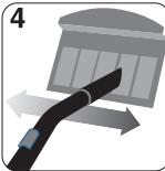
- To maintain the performance of the device, about twice per year, clear the dust.
Do not use abrasive products.
- For models with a fan, use a vacuum cleaner to clear the air inlet and outlet grids, as well as the filter. The fan is fitted with an antidust filter which, when clogged, can result in its stoppage (lit on the device).
For better use, clean your filter regularly, according to the following instructions:
 | Red indicator |  | Power off the heating. |  | Extract the filter from the back of the machine. |
 | Clean the filter. | 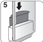 | Refit the filter. |  | Wait 10 minutes before restarting the heating. |
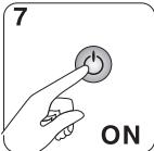 | Restart the heating. | ||||
WARRANTY CONDITIONS
KEEP THIS DOCUMENT IN A SAFE PLACE
(To be presented by the user only in the event of a claim)
- The guarantee period is two years from the date of installation or purchase and may not exceed 30 months from the date of manufacture in the absence of a receipt.
- The guarantee covers the replacement and supply of components recognised as being defective, excluding any damages or interest.
- The user is responsible for any labour or transport costs.
- The guarantee does not cover any damage arising from improper installation, abnormal use or non-observance of the requirements of the said instructions for installation and use.
- The stipulations of the present guarantee conditions do not exclude any of the purchaser's legal rights of guarantee against faults or hidden defects, which are applicable in all cases under the stipulations of Articles 1641 of the Civil Code.
- Present this certificate to your distributor or installer only in the event of a claim, together with your purchase invoice.
TYPE OF DEVICE*:
SERIAL NUMBER*:
CUSTOMER'S NAME AND ADDRESS: ....
* This information can be found on the information plate situated on the left-hand side of the device.
ATLANTIC INTERNATIONAL
Phone: 00 33 146836000
Fax : 00 33 146836001
GARANTIE
ELEKTRONISCHE RADIATOR VOOR HANDDOCKEN
RADIADOR SECA TOALLAS
RADIADOR SECO-TOALHAS
natural_image
Illustration of a white horizontal heater with horizontal stripes and a small circular patch on the side (no text or symbols)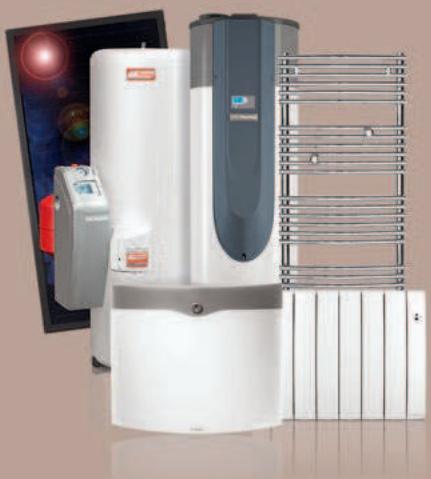
natural_image
Exterior view of a modern air conditioning unit with control panel and display screen (no visible text or symbols)Thermor, la garantie confort