AMADEUS EVOLUTION - Electric heating THERMOR - Free user manual and instructions
Find the device manual for free AMADEUS EVOLUTION THERMOR in PDF.
User questions about AMADEUS EVOLUTION THERMOR
0 question about this device. Answer the ones you know or ask your own.
Ask a new question about this device
Download the instructions for your Electric heating in PDF format for free! Find your manual AMADEUS EVOLUTION - THERMOR and take your electronic device back in hand. On this page are published all the documents necessary for the use of your device. AMADEUS EVOLUTION by THERMOR.
USER MANUAL AMADEUS EVOLUTION THERMOR
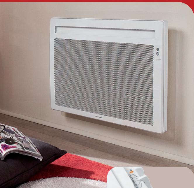
Installation & operating manual
Amadeus évolution
PANNEAU
RAYONNANT
Radiant panel
Amadeus évolution
PANNEAU RAYONNANT
Radiant panel


Preparing the installation of the panel heater 23
Unlocking the panel heater's hanging frame 24
Fixing the hanging frame to the wall 24
Connecting the panel heater 25
Locking the panel heater on the hanging frame 26
Operation 27
Use
Heating your room: how to use Comfort mode 28
Automatically lowering the temperature of your room: how to use Eco mode 29
Programming the heating period: how to use Programming mode 30
How to use the energy-saving functions 31
Advice
If you will be absent for a period of 2 to 24 hours. 34
If you will be absent for a period of more than 24 hours 35
Locking the panel heater's settings 35
Maintenance 37
Troubleshooting 38
Warranty conditions 40
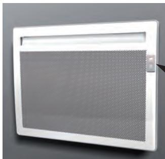
The device you have just purchased was submitted to many tests and checks ensuring its quality. We thank you for your choice ant trust. We hope you will be fully satisfied.
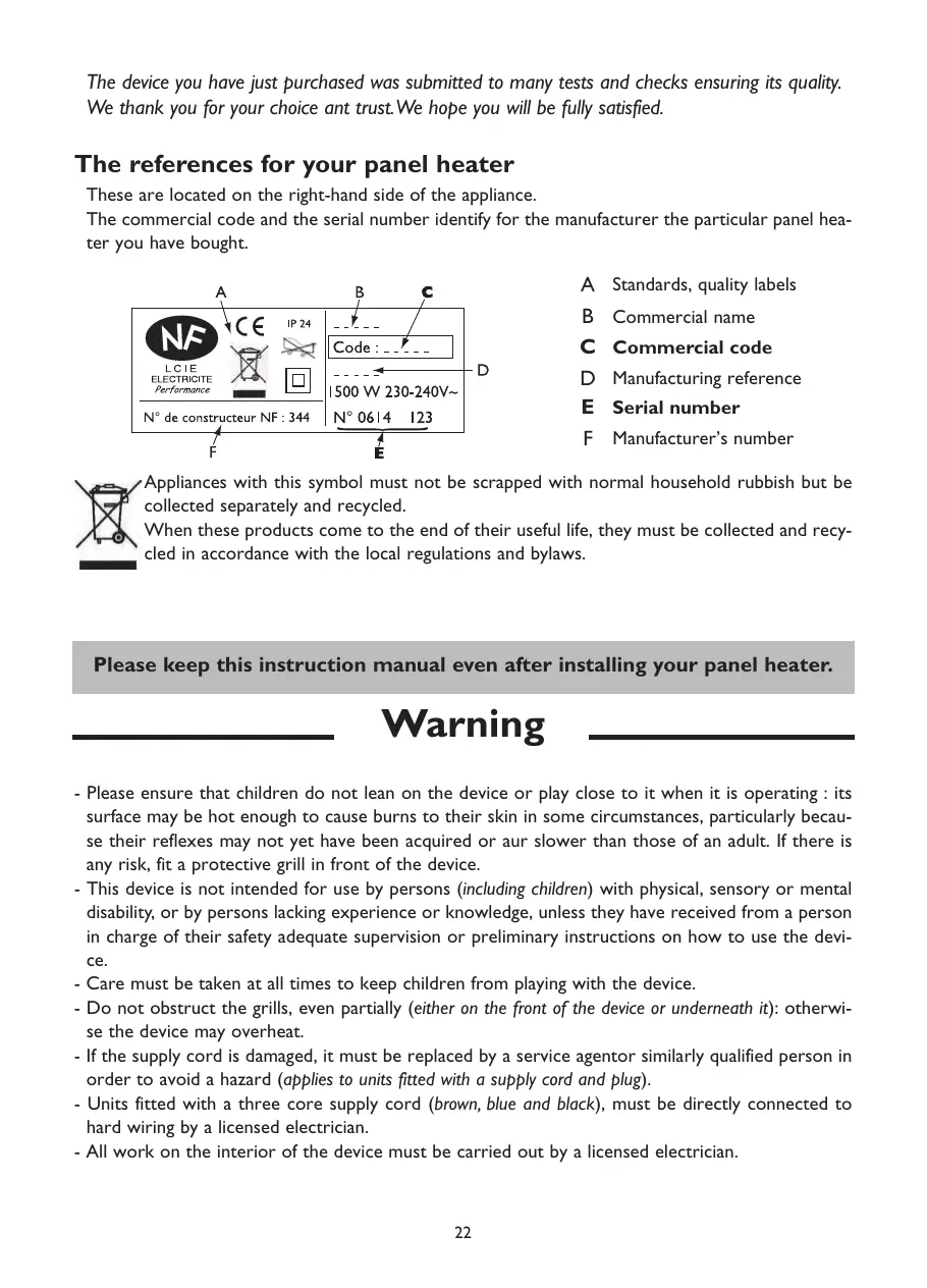
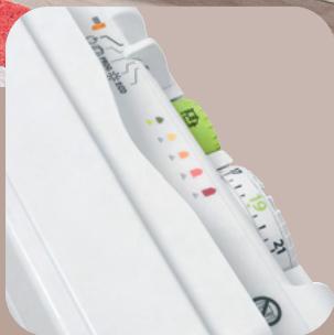
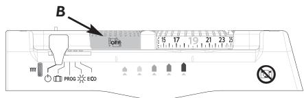
The references for your panel heater
These are located on the right-hand side of the appliance.
The commercial code and the serial number identify for the manufacturer the particular panel heater you have bought.
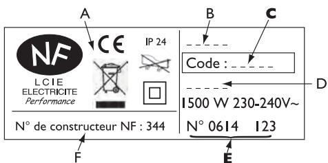
A Standards, quality labels
B Commercial name
C Commercial code
D Manufacturing reference
E Serial number
F Manufacturer's number
Appliances with this symbol must not be scrapped with normal household rubbish but be collected separately and recycled.
When these products come to the end of their useful life, they must be collected and recycled in accordance with the local regulations and bylaws.
Please keep this instruction manual even after installing your panel heater.
Warning
- Please ensure that children do not lean on the device or play close to it when it is operating : its surface may be hot enough to cause burns to their skin in some circumstances, particularly because their reflexes may not yet have been acquired or aur slower than those of an adult. If there is any risk, fit a protective grill in front of the device.
- This device is not intended for use by persons (including children) with physical, sensory or mental disability, or by persons lacking experience or knowledge, unless they have received from a person in charge of their safety adequate supervision or preliminary instructions on how to use the device.
- Care must be taken at all times to keep children from playing with the device.
- Do not obstruct the grills, even partially (either on the front of the device or underneath it): otherwise the device may overheat.
- If the supply cord is damaged, it must be replaced by a service agentor similarly qualified person in order to avoid a hazard (applies to units fitted with a supply cord and plug).
- Units fitted with a three core supply cord (brown, blue and black), must be directly connected to hard wiring by a licensed electrician.
- All work on the interior of the device must be carried out by a licensed electrician.
PREPARING THE INSTALLATION OF THE PANEL HEATER
Installation guidelines
- This device was designed to be installed in residential premises. In any other case, please call your distributor.
- Installation must comply with the standards currently enforced in the country of use.
- The panel heater must be supplied with 230V single-phase 50Hz
- In damp areas such as bathrooms and kitchens, you must install the connection box at least 25cm above the floor.
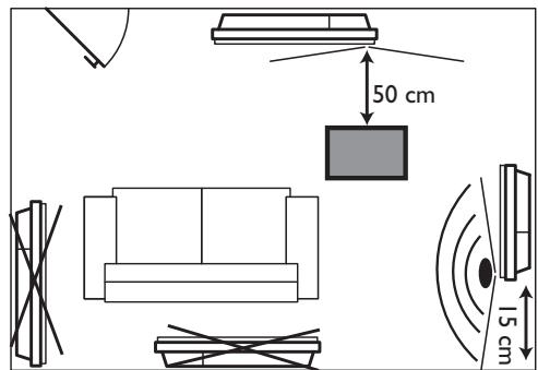
Keep the panel heater away from any draughts that may interfere with its operation (e.g.: under a centrally controlled fan, etc...).
Do not install the heater under a fixed socket.
The panel heater is fitted with a detection system, whose sensor is located on the front of the appliance.
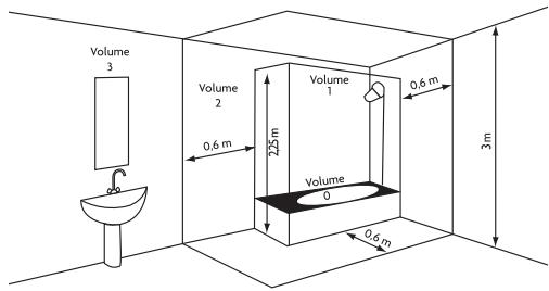
| Volume Ⅰ | No electrical appliance |
| Volume Ⅱ | Class Ⅱ IPX24 electrical appliance |
| Volume Ⅲ | Class Ⅱ electrical appliance |
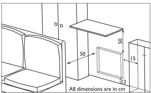
Comply with the minimum distances from any furniture units when positioning the appliance.
To optimise absence detection by your appliance, do not install it in a closed off corner or behind furniture.
We strongly advise against installing vertical machines above an altitude of 1000m (risk of faulty operation).
Installing a machine at altitude causes an increase in air output temperature (of the order of 10^ per 1000m above sea level).
It is forbidden to install a vertical machine horizontally or vice versa.
Do not use the device in mobile, on feet or on casters.
UNLOCKING THE PANEL HEATER'S HANGING FRAME
We recommend that you place the panel heater face down on the floor, taking care to protect its front surface from scratches.

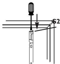
Take a flat-bladed screwdriver and lift the slider, taking care not to bend it.
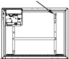

While keeping the slider raised, push the hanging frame towards the bottom of the heater to release the upper brackets S2. We recommend that you wear protective gloves.

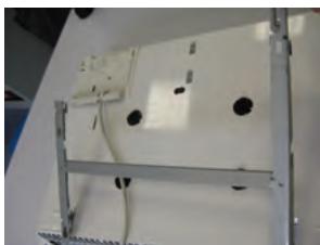
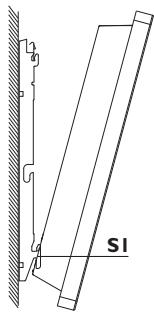
Swivel the hanging frame downwards on the lower brackets SI.
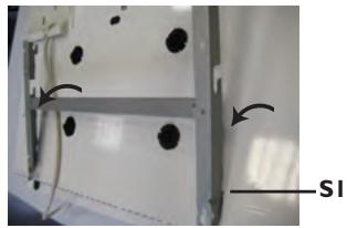

Remove the hanging frame.
FIXING THE HANGING FRAME TO THE WALL

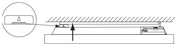
Place the hanging frame on the floor against the wall. Locate drilling points A.
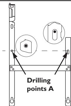
Drilling points A show the position for the lower fastenings.

Refit the hanging frame, lining up with drilling points A to find drilling points B (you can also use a level).
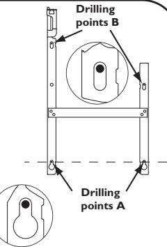
Drilling points B show the position for the upper fastenings.

Drill the 4 holes and insert the wall plugs. Use suitable wall plugs when fitting on a specific support (e.g. plasterboard wall).

Position the hanging frame and screw it down.
CONNECTING THE PANEL HEATER
Connection rules and regulations
- The panel heater must be supplied with 230V single-phase current at 50Hz .
- The panel heater's power supply must be directly connected to the main supply after the circuit breaker without any intermediate switch.
- The panel heater's power cable must be connected to the main supply via a connection box. In damp areas, such as bathrooms and kitchens, the connection box must be installed at least 25cm above the floor.
- An Earth connection is prohibited. Do not connect the pilot wire (black wire) to Earth.
- The installation must be fitted with an all-pole cut-off switch with a contact opening distance of at least 3mm .
- If the power cable is damaged, it must only be replaced by an electrician.
- If you are using the pilot wire and it is protected by a 30mA differential (e.g.: bathroom use), the pilot wire's power supply must also be protected on this differential.
Wiring diagram for the heating panel
- Cut off the power supply and connect the wires as shown in the following diagram:
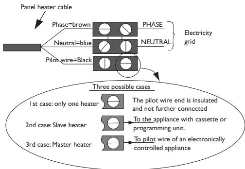
- You can connect the pilot wire if your home is equipped with a programming unit or controller. In this case, make the following checks according the selected mode (Comfort, Eco, etc.) to that the programming instructions are being transmitted correctly:
| COMFORT ® | ECO ECO | FROST ® | SWITCH-OFF OF HEATING AND POWER CUT-OFF | COMFORT -1°C ® | COMFORT -2°C ® | |
| SIGNAL TO BE TRANSMITTED | — | — | — | — | ←5' 3" | ←5' 7" |
| MEASUREMENT BETWEEN THE PILOT WIRE AND NEUTRAL | 0 Volt | 230 Volts | -115 Volts negative | +115 Volts positive | 230 Volts for 3 s | 230 volts for 7 s |
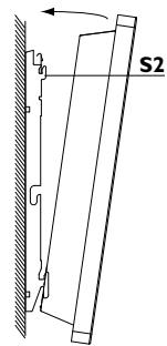
LOCKING THE PANEL HEATER ONTO THE HANGING FRAME
1
Position the tilted panel heater on brackets S1.
2
Pivot the panel heater upwards and lift it to position it on brackets S2.
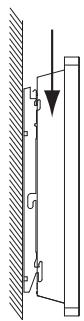
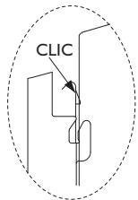
3
Lower the panel heater onto the hanging frame. A click tells you that the panel heater is fastened and locked in place.

To unlock the panel heater from the hanging frame, take a flat-bladed screwdriver and push the slider (located on the top left-hand corner of the hanging frame behind the appliance) towards the wall.
Lift the panel heater while holding the slider in place with your screwdriver. Tilt it forwards and then remove it from brackets S1.
Operation
You can run your panel heater in several modes:
- Comfort mode (♂) which enables you to have the right ambient temperature.
- Eco mode (Eco) which enables you to lower the temperature in your room when you will be away from your home for a long time or during the night, especially in bedrooms.
- Programming mode (PROG) which enables you to programme the Comfort and Eco modes according to how a room will be occupied by means of a programming system (as an option).
- Frost mode ( ) which enables you to maintain a temperature of around 7^ during an absence of more than 24 hours, for example.
- Stand-by mode ( ) which enables you to stop your panel heater from heating.
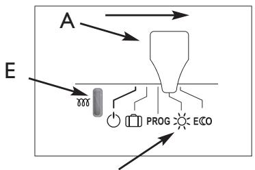
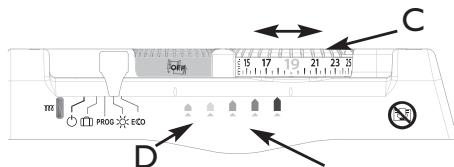
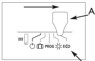
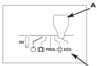
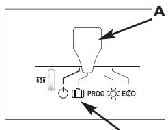
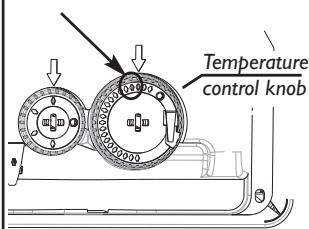
Control box
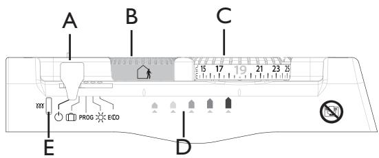
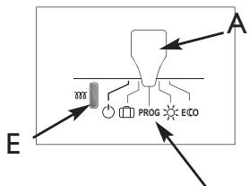
A Mode selection cursor
B Control knob for the energy-saving functions
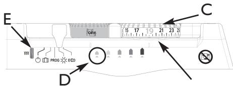
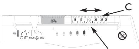
C Control knob for the Comfort temperature
D Consumption indication lights
E Heating light
The energy-saving functions (please refer to page 31)

Activate airing detection

Activate absence detection

Activate airing and absence detection

Deactivate airing and absence detection
After 2 minutes of inactivity, the light on indicator D goes out automatically.
HEATING YOUR ROOM: HOW TO USE COMFORT MODE

This mode enables you to have the ambient temperature you desire in your room. The consumption indicator lights enable you to optimise your setting (see page 33).
1
Set the cursor A to position The heating light E illuminates if the room's temperature is below that indicated on the control knob C.
2
Set the temperature knob C to the desired temperature. For a setting of around 19^ , only the first light (green) on the indicator D comes on to indicate optimised consumption.
The heating light E illuminates if the room's temperature is below that indicated on the control knob C.
3
Wait at least 6 hours for the room's temperature to stabilise.
If the room's temperature is acceptable, setting is complete.
4
If the room's temperature is not acceptable, progressively adjust the control knob C using the notches (one notch at a time).
The higher the temperature shown on the control knob C the more the indicator light D moves to the right.
AUTOMATICALLY LOWERING THE TEMPERATURE IN YOUR
ROOM:HOW TO USE ECO MODE

This involves a lowering of the temperature by around 3.5^ with respect to the Comfort temperature , set on the control knob C. We recommend that you use this mode when you will be absent for 2 to 24 hours, or during the night, especially in bedrooms.
GB
Set the cursor A to position ECO The Comfort temperature will be lowered by about 3.5^
This mode enables you to lower the temperature automatically without altering the Comfort setting on the control knob C.
PROGRAMMING THE HEATING PERIOD: HOW TO USE PROG MODE PROG
Using the programming, you can adjust your panel heater's settings to suit your lifestyle.
By connecting the pilot wire to a programmer, or if you use an on-board programmer (available as an option), you can programme your Comfort 品 and ECO temperature periods (please refer to the instructions included with your programmer).
You can connect several appliances to one programmer.
The temperature set on the control knob C is the base temperature that will serve as a reference for the desired temperature according to the programming.
| Order on your program- ming box | Lower |
| COMFORT -1°C | -1°C with respect to the setting on the knurled knob C |
| COMFORT -2°C | -2°C with respect to the setting on the knurled knob C |
| ECO | -3.5°C with respect to the setting on the knurled knob C |
| FROST | Ambient temperature held at around 7°C. |
| STOP | Immediate switch off of the heating (used to disconnect the power). |
Set the Comfort temperature that will serve as a base for programming my reductions in temperature:
Set the temperature control knob C to the desired temperature.
2 Set the cursor A to position PROG
The heating light E illuminates if the room's ambient temperature is below the desired temperature for the selected mode (Comfort temperature in Comfort mode and reduced temperature in Eco mode ECO).
NB: When there are no instructions from the pilot wire, the appliance heats in Comfort mode. The instructions for Frost [ ] and Stop [ ] take priority over Eco mode ECO and Comfort mode. The changeover time is around 12 seconds when switching from Comfort mode to Eco mode ECO
HOW TO USE THE ENERGY-SAVING FUNCTIONS
To use these functions, we recommend that you set the cursor A to Comfort or Programming PROG mode.
These functions are in addition to the programming functions.
ACTIVATING THE AIRING DETECTION FUNCTION
Do not heats the room while it is being ventilated allow you to save energy. If you do not turn off your heater when a window is open for a long time, the airing function stops your device from heating when it is not necessary: your heater automatically detects when the window is opened or closed and therefore saves energy.
Your device reacts to an open or close window according to several variables, especially
- the temperature settings programmed for the room
- the outside temperature
- the location of your heater, etc.
By detecting whether the window is open or closed,
the airing function helps you to be environmentally friendly: you save energy by not heating your house when you ventilated it.
Turn control knob B to position
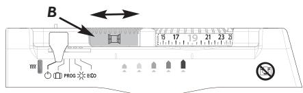
To activate the airing detection function:
The operating instructions are for 7^ ± 3^ for the whole time that your room is being aired. When you close the window, your panel heater will return to its initial operating mode.
After 2 hours, the appliance starts heating again in any case. The maximum expected pairing period is 2 hours.
NB: If the function does not meet your requirements, you can manually stop the panel heater from heating (Stand-by mode ). When the function is running, the green LED flashes slowly.
ACTIVATING THE ABSENCE DETECTION FUNCTION
The absence detection function enables you to lower the temperature setting for your room automatically, as soon as you leave it.
To activate the absence detection function:
Turn control knob B to position
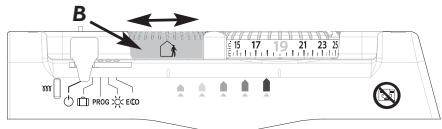
If your panel heater detects no one in the room, it automatically lowers the temperature setting progressively to 3.5^ lower than the Comfort temperature setting.
The programming instructions (PROG) take priority over absence detection.
ACTIVATING THE AIRING+ ABSENCE DETECTION FUNCTION
To activate the airing + absence detection function:
Turn control knob B to position
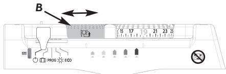
The two functions described above are activated.
DEACTIVATING THE ENERGY-SAVING FUNCTIONS
To deactivate the energy-saving functions:
Turn control knob B to position
The energy-saving functions are deactivated.
To optimise your setting:
- Activate the energy-saving functions (knob B),
- Adopt "19°C" as a standard ( I^ less = 7% savings in energy).
All the panel heaters in the same room must be fitted with the same function capabilities. The energy-saving functions must be set in the same way on each heater.
We do not recommend the use of the "airing" and "airing + absence detection" functions in corridors and rooms located close to an entrance door from outside your home or from the garage.
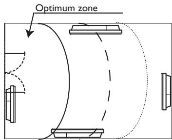
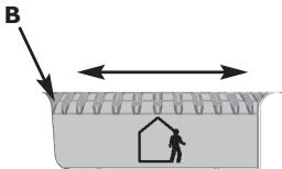
Absence detection is made from a height of over 45cm (Diagram 1) and operates progressively (Diagram 2):
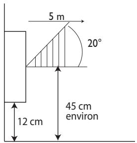
Diagram I
E.g.: Your appliance is set to 19^ , in Comfort mode (whether programmed or not) At 9:00, it detects your absence.
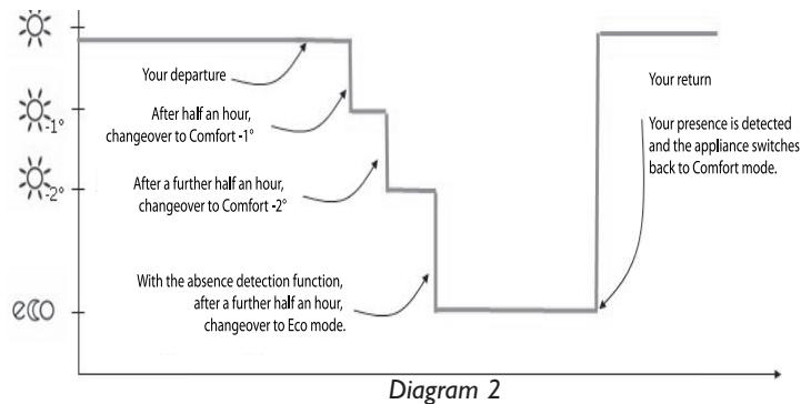
At 9:30, its operating instructions are set to 18^
At 10:00, its operating instructions switch to 17^ .
At 10:30, its operating instructions switch to 15.5^ .
CONSUMPTION INDICATOR
The energy consumed by an electrical heating appliance depends, among other things, on the temperature required. The temperature recommended by the public authorities is 19^ , in Comfort mode ( 15.5^ in Eco mode).
The "Consumption Indicator" function enables you to position yourself in accordance with this recommended temperature.
Therefore, depending on the temperature required:
- If the second orange or red LED is lit, you can behave more responsibly by lowering your required temperature significantly.
- If the first orange LED is lit, you can behave more responsibly by lowering your required temperature slightly.
- If the green LED is lit, you are at the recommended temperature and are already behaving responsibly.
It is pointless to set your panel heater to the maximum setting; your room's temperature will not rise any faster.
All the appliances in the same room must be set in the same way.
IF YOU WILL BE ABSENT FOR A PERIOD OF 2 TO 24 HOURS
Set the cursor A to ECO
Your panel heater will maintain a temperature approximately 3.5^ lower than the Comfort temperature you have set.
NB: The absence detection sensor also enables you to ensure an automatic reduction in temperature during your absence (see the section "How to use the energy-saving functions").
IF YOU WILL BE ABSENT FOR A PERIOD OF MORE THAN 24 HOURS
Set the cursor A to []
Your panel heater will maintain a temperature of 7^± 3^ corresponding to the Frost setting.
LOCKING THE PANEL HEATER'S SETTINGS
Release the panel heater from its hanging frame (see Page 26).
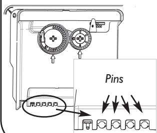
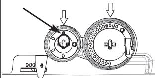
LOCKING THE TEMPERATURE CONTROL KNOB
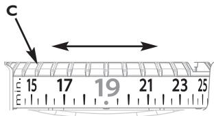
Set the control knob C to the desired position.
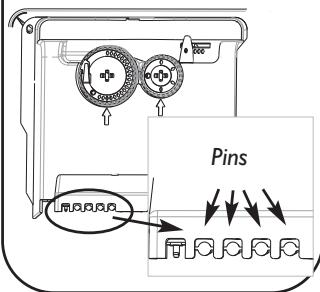
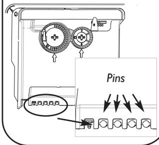
2 Remove one pin from its holder on the back of the control box.
3 Place the locking pin in the hole opposite the arrow.
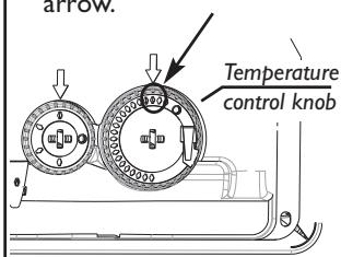
Now the setting on the control knob C cannot be altered,
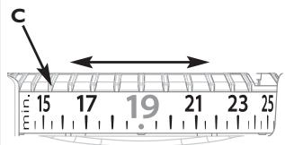
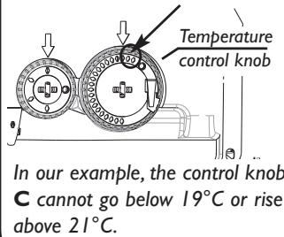
Set the control knob C to the maximum temperature desired.
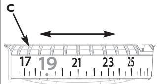
In the example above, the maximum temperature is 21^
2 Remove one pin from its holder on the back of the control box.
3 Place the locking pin in the hole to the left of the arrow.
4 Set the control knob C to the minimum temperature desired.
In the example above, the minimum temperature is 19^
5 Remove one pin from its holder on the back of the control box.
6 Place the locking pin in the hole to the right of the arrow.
Set the control knob B to the desired position.
2 Remove one pin from its holder on the back of the control box.
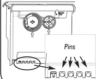
3 Place the locking pin in the hole opposite the arrow.
Energy-saving functions control knob
Now the setting on the control knob B cannot be altered.
Lock the panel heater onto its hanging frame (see Page 24).
MAINTENANCE
To maintain your panel heater's performance, you must dust it approximately twice a year. Never use abrasive products or solvents.
TROUBLESHOOTING
| PROBLEM ENCOUNTERED | CHECKS TO BE MADE |
| The panel heater does not heat. | - Check that the cursor is on position - If you are operating under programming, check that the programmer is in COMFORT mode. - Ensure that the installation's circuit breakers are engaged and that the power cut-off (if you have one) has not cut off the power to the panel heater. - Check the air temperature in the room: if it is too high, the heating light E does not illuminate: the panel heater does not heat. - Check that the control knob B is not in Airing position and that there are no draughts. |
| The panel heater heats all the time. | - Check that the panel heater is not in a draught or that the temperature setting ha not been altered. - There may be a fluctuation in the main power supply. If there is a problem (blocked thermostat...), cut off the power to the panel heater (fuse, circuit breaker) for approximately 10 minutes and then switch it back on. - If the phenomenon recurs frequently, have your electricity utility check the power supply. |
| The panel heater's surface is very hot. | It is normal for the panel heater to be hot when it is operating; the maximum surface temperature is restricted in accordance with the NF electrical performance standard. However, if you think that your panel heater is still too hot, check that the output is suitable for the area of your room (we recommend 100W / m2) and that the heater is not placed in a draught, which would interfere with its self-regulation; also check that the installation guidelines have been followed (curtains, etc.) |
| The panel heater does not follow its programming instructions. | Ensure that the energy controller or programming unit is being used correctly (see the user's manual). |
| The heating light E flashes rapidly (lit 0.5 seconds, unlit 0.5 seconds). | The measurement sensor has deteriorated. Contact your installer. |
| The consumption indicator light D flashes rapidly (lit 0.5 seconds, unlit 0.5 seconds). | Your panel heater's absence detector is disconnected or is not working. Contact your installer. The functions other than absence detection still remain operational. |
| The heating light E flashes slowly (lit l second, unlit l second). | Your panel heater's potentiometer has deteriorated. Contact your installer. |
| The airing detector does not react | Your panel heater's environment may interfere with this function's ability to react (e.g.: distance of the panel heater from the window, the external tem- perature, the room's level of insulation, etc.). During airing, switch the cur- sor A to Stand-by mode Ⓞ. |
| - The ambient tem- perature is diffe- rent from the tem- perature set on the control knob C. - Control knob C is set to 19°C, a light other than the green one is lit. | If your ambient temperature, after 6 hours without adjusting the mode or the setting, still differs from that set on the control knob, you can recalibra- te your panel heater. If a pilot wire kit or a carrier current interface is fixed to the back of your panel heater, it is best to remove this first. For recalibrating the heater, the temperature on the control knob C must be set between 18°C and 23°C. While holding knob C, unlock the locking pin behind the knob with a flat- bladed screwdriver. Turn the knob's numbered part C1 while hol- ding the upper part C2 to match up the room's temperature with that shown on the knob. Take care not to turn the upper part C2: this would disrupt the panel heater's controls. Relock the pin by pressing it down. |
If you do not succeed in solving your problem, contact your local installer and have the details of your heater's references, the room's temperature and the programming system (if any) to hand.
Any intentional damage (perforation, scratches) to the absence detector's lens rescinds your appliance's warranty.
WARRANTY CONDITIONS
- The guarantee period is two years from the date of installation or purchase and may not exceed 30 months from the date of manufacture in the absence of a receipt.
- The guarantee covers the replacement and supply of components recognised as being defective, excluding any damages or interest.
- The user is responsible for any labour or transport costs.
- The guarantee does not cover any damage arising from improper installation, abnormal use or non-observation of the requirements of the said instructions for installation and use.
- The stipulations of the present guarantee conditions do not exclude any of the purchaser's legal rights of guarantee against faults or hidden defects, which are applicable in all cases under the stipulations of Articles 1641 of the Civil Code.
- Present this certificate to your distributor or installer only in the event of a claim, together with your purchase invoice.
TYPE OF DEVICE*:
SERIAL NUMBER*:
CUSTOMER'S NAME AND ADDRESS:
- This information can be found on the information plate situated on the left-hand side of the device.
ATLANTIC INTERNATIONAL
Tel: (33) 146836000
Fax: (33) 146836001