
EG 1150 H - Microtome LEICA - Free user manual and instructions
Find the device manual for free EG 1150 H LEICA in PDF.

| Product type | Paraffin embedding station (microtome) |
| Brand and model | Leica EG1150H |
| Dimensions (H x W x D) | 360 mm x 500 mm x 640 mm |
| Weight | Approximately 22 kg |
| Power supply | 100-120 V / 230-240 V, 50/60 Hz, 1100 VA |
| Working temperature | 55 °C to 70 °C, adjustable in 5 °C increments |
| Paraffin tank capacity | Approximately 3 liters |
| Cassette warmer capacity | Approximately 100 cassettes |
| Mold warmer capacity | Approximately 50 molds |
| Main functions | Mold filling, temperature maintenance, time programming, intensive mode |
| Work area lighting | Halogen lamp 12 V / 5 W, individually adjustable |
| Heating elements | Tank, work area, warmers, forceps holder |
| Cooling point | Integrated in the work area for rapid solidification |
| Maintenance and cleaning | Daily cleaning with suitable products, use the provided plastic spatula |
| Safety | Overheating fuses, automatic circuit breaker, marked hot surfaces |
| Spare parts and repairability | Spare fuses provided, halogen lamp replaceable by user |
| General information | Use by qualified personnel only, follow safety instructions |
Frequently Asked Questions - EG 1150 H LEICA
User questions about EG 1150 H LEICA
0 question about this device. Answer the ones you know or ask your own.
Ask a new question about this device
Download the instructions for your Microtome in PDF format for free! Find your manual EG 1150 H - LEICA and take your electronic device back in hand. On this page are published all the documents necessary for the use of your device. EG 1150 H by LEICA.
USER MANUAL EG 1150 H LEICA
Paraffin Embedding Station
Instruction Manual
Leica EG1150H
V2.2 English, Rev. B - 12/2009
Always keep this manual near the instrument.
Read carefully prior to operating the instrument.
The information, numerical data, notes and value judgments contained in this manual represent the current state of scientific knowledge and state-of-the-art technology as we understand it following thorough investigation in this field.
We are under no obligation to update the present manual periodically and on an ongoing basis according to the latest technical developments, nor to provide our customers with additional copies, updates etc. of this manual.
For erroneous statements, drawings, technical illustrations, etc. contained in this manual we exclude liability as far as permissible according to the national legal system applicable in each individual case. In particular, no liability whatsoever is accepted for any financial loss or consequential damage caused by or related to compliance with statements or other information in this manual.
Statements, drawings, illustrations and other information as regards contents or technical details of the present manual are not to be considered as warranted characteristics of our products.
These are determined only by the contract provisions agreed between ourselves and our customers.
Leica reserves the right to change technical specifications as well as manufacturing processes without prior notice. Only in this way is it possible to continuously improve the technology and manufacturing techniques used in our products.
This document is protected under copyright laws. Any copyrights of this document are retained by Leica Biosystems Nussloch GmbH.
Any reproduction of text and illustrations (or of any parts thereof) by means of print, photocopy, microfiche, web cam or other methods — including any electronic systems and media — requires express prior permission in writing by Leica Biosystems Nussloch GmbH.
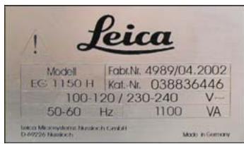
For the instrument serial number and year of manufacture, please refer to the name plate at the left side of the instrument.
Leica Biosystems Nussloch GmbH
Published by:
- Important notes 5
1.1 Symbols used in the text and their meanings 5
1.2 Specified use and application 5
1.3 User group 5
1.4 Instrument type 5 - Safety 6
2.1 Safety regulations 6
2.2 Safety instructions 6
2.3 Built-in safety devices 8 - Instrument components and specifications 9
3.1 Specifications 9
3.2 Overview - instrument parts 10
3.3 Instrument specifications 11 - Commissioning 12
4.1 Unpacking and installation 12
4.3 Package contents 13
4.2 Location conditions 13
4.4 Necessary assembly work 14
4.5 Optional accessories 16
4.6 Electrical connection 17 - Operation 18
5.1 Instrument parts/functions 18
5.2 Switching the instrument on 23
5.3 Control panel functions 24
5.4 Operating modes 25
5.5 Time-program control 26
5.6 Instrument heater 28 - Cleaning and maintenance 30
6.1 Cleaning the instrument 30
6.2 Maintenance instructions 31 - Troubleshooting 32
7.1 Possible faults 32
7.2 Replacing the halogen lamp 35
7.3 Changing a fuse 36 - Warranty and service 38
1.1 Symbols used in the text and their meanings

Warnings and cautions appear in a gray box and are marked by a warning triangle .

Notes, i.e. important information for the user, appear in a gray box and are marked with the symbol i

Solvents and reagents that are inflammable are marked with this symbol.
This warning symbol indicates the surfaces on the instrument that are hot during operation. Avoid direct contact to prevent risk of burning.
(5)
Figures in brackets refer to item numbers in figures.
ENTER
Function keys that have to be pressed on the input screen, are displayed in bold type and capital letters.
1.2 Specified use and application
The Leica EG1150H is a modern paraffin embedding station with microprocessor control. It is designed for embedding histological tissue specimens in molten paraffin for use in pathology laboratories and only for the following tasks:
- Melt solid paraffin for sample embedding and maintain the molten paraffin at the required temperature.
- Fill the molds, in which the tissue specimens were placed, with paraffin.
- Heat and maintain the temperatures of embedding cassettes with specimens and molds as well as the required forceps.
Any other use of the instrument will be considered as improper use!
1.3 User group
- The Leica EG1150H may only be operated by qualified personnel.
- The user must read the operating instructions supplied and be familiar with all the instrument's technical details before any work on the instrument can be carried out.
1.4 Instrument type
All information in this instruction manual applies only to the instrument type indicated on the title page.
A name plate with the serial number is attached to the back of the instrument.

Be sure to comply with the safety instructions and warnings provided in this chapter. Be sure to read these instructions, even if you are already familiar with the operation and use of other Leica products.
2.1 Safety notes
This instruction manual contains important instructions and information regarding the operational safety and maintenance of the instrument.
The instruction manual is an important part of the product, which must be read carefully prior to start-up and use and must always be kept near the instrument.
This instrument has been built and tested in accordance with the safety regulations for electrical measuring, control, regulating and laboratory devices.
To maintain this condition and ensure safe operation, the user must observe all notes and warnings contained in this Operating Manual.

If additional requirements on accident prevention and environmental protection exist in the country of operation, this instruction manual must be supplemented by appropriate instructions to ensure compliance with such requirements.

For current information about applicable standards, please refer to the CE declaration for the instrument and to our Internet site: http://www.leica-microsystems.com

The protective devices on both instrument and accessories may neither be removed nor modified. Only service personnel qualified by Leica may repair the instrument and access the instrument's internal components.
2.2Warnings
The safety devices installed in this instrument by the manufacturer only constitute the basis for accident prevention. Primarily responsible for accident-free operation is above all the owner of the instrument and, in addition, the designated personnel who operates, services or cleans the instrument.
To ensure trouble-free operation of the instrument, make sure to comply with the following instructions and warnings.
Safety instructions - safety regulations on the instrument itself

Safety regulations marked with a warning triangle on the instrument itself mean that when operating or exchanging respective parts of the instrument, the correct operating steps as described in the instruction manual supplied, must be adhered to. Non-observation can cause accidents, injuries and/or damage to the instrument/accessories.
Certain surfaces of the instrument are hot during operation under normal conditions. They are marked with this warning sign. Touching these surfaces can cause burns.
Safety instructions - transport and installation

After unpacking the instrument it may only be transported in an upright position.
Place the instrument on a laboratory table and adjust it to a horizontal position.
The instrument must not be exposed to direct sunlight (window)!
Plug the instrument only into a grounded mains socket. The protective effect may not be eliminated by an extension cable without a protective grounding conductor.
The instrument automatically recognizes the applied voltage/frequency.
The installation location must be well-ventilated; there should be no ignition sources there of any kind.
The instrument may not be operated in hazardous locations.
Extreme temperature fluctuations between storage facility and setup site as well as high humidity may cause condensation to form. In this case, wait at least two hours before switching on.
Safety instructions - working with the instrument

Paraffin is flammable and should therefore be handled with due care. Do not use sharp tools to remove solidified paraffin from the work areas, as this may destroy the coating on the surface. Use the plastic spatula supplied with the instrument.
During operation, the paraffin reservoir, mold warmer, cassette warmer, work area as well as the forceps holder are hot.
Risk of burning!
Do not store any combustible and flammable substances near the instrument. There is a fire hazard if work with an exposed flame (e.g. Bunsen burner) is carried out in the direct vicinity of the instrument (solvent vapors). Therefore a minimum safety distance of 2 meters must be adhered to!
Hazards - servicing and cleaning

Switch off the instrument each time before servicing and pull out the mains plug.
When using cleaners, please comply with the safety instructions of the manufacturer and the laboratory safety regulations.
Before changing defective fuses, the instrument has to be disconnected from the mains.
Only fuses that are easily accessible may be replaced by the user.
Set the standby switch to "Standby" (U) when replacing the halogen lamp and pull the power cable out of the mains socket.
During operation and cleaning, do not allow any liquid to penetrate inside the instrument and the transporting arm.
2.3 Built-in safety devices
The instrument is equipped with the following safety features and devices:
Fuses in the heating elements
All resistance mats of the instrument are equipped with overheating fuses, which switch the heating element off if overheated.
Automatic circuit breaker in standby switch
An automatic circuit breaker is located in the standby switch. This circuit breaker separates the power electronics from the mains power supply in the event of a short-circuit.
In this case, the standby switch jumps to the position "0" = 0ff.

Note that the only way the user has for complete disconnection from the mains supply is disconnection of the mains plug.
3.1 Specifications
General data
Approvals: The approval symbols relating to this instrument are located on the rear of the instrument next to the nameplate.
Power voltages: 100-120 V, 50/60 Hz
230-240 V, 50/ 60 Hz
Input: 1100 VA
Class of protection:
Degree of pollution: 2
Overvoltage category: II
Operating temperature range: +18^ C to +40^ C
Working temperatures: 55^ to 70^ , adjustable in 5 degree (K) increments.
Relative air humidity: maximum 60% non-condensing.
1) according to IEC-1010, UL 3101, EN 61010
Fuses
Standby switch: Circuit breaker manufactured by ETA,
model 3120-F421-P7T1-W01D-5A
Fine-wire fuses 6.3 × 32 ~mm : 2 × T 2.0 ~A; 2 × T 3.2 ~A; T 2 × 4.0 ~A; T 2 × 5.0 ~A; T 2 × 6.25 ~A
Fuse type: Co. Schurter: type Fst
Dimensions and weight
Dimensions:
Height: 360 mm
Width: 500 mm
Depth: 640 mm
Weight: approx. 22kg
Capacities
Paraffin reservoir: approx. 3 l
Cassette warmer: approx. 100 cassettes
Mold warmer: approx. 50 molds
Programmable parameters
Temperature: Paraffin reservoir/dispenser
(heating-up time = 4h )
Mold warmer, cassette warmer, work area
Time: Working days, current weekday
Working times (start, end), time
3.2 Overview - instrument parts
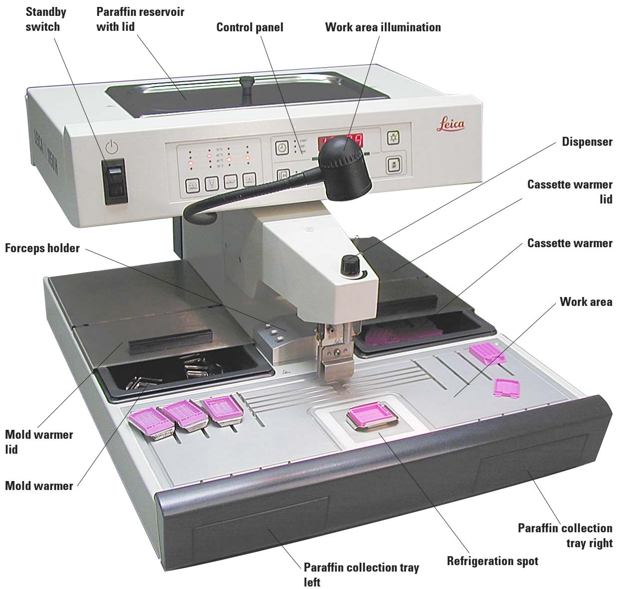
Fig. 1
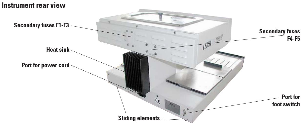
Fig. 2
3.3 Instrument specifications
- Paraffin reservoir with a capacity of 3 liters.
- The paraffin flow is activated by means of a height-adjustable, pivotable clip - activated either manually by the mold or a foot switch (optional).
- Controllable flow rate.
- Removable, heatable (indirectly, via the work surface) paraffin collection trays.
- Spacious, easy-to-clean, heated work area, with integrated refrigeration spot, also for extra large cassettes ('Super Mega Cassettes') with paraffin flow system.
- Warmers for cassettes and/or molds with sliding lid, removable and interchangeable.
- Removable, heated forceps holder for 6 forceps, accessible from both sides.
- Optimum illumination of the work surface by individually adjustable halogen lamp.
- Temperature range of cassette and mold warmer, work area and paraffin reservoir adjustable from 55^ to 70^ .
- Permanent temperature display for all the work areas.
- The beginning and end of the work time and work days can be programmed.
4.1 Unpacking and installation

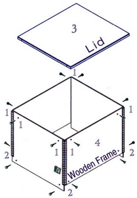
The unpacking instructions are attached to the outside of the transport crate. Fig. 3 shows the design of the original packaging.
The numbers indicate the sequence of disassembling and reassembling.
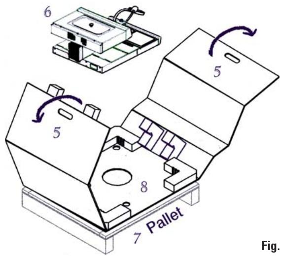
- To lift up the instrument (6), hold it at the front and rear of the base plate (Fig. 4) and lift it from the foam padding (8).

Important!
Lifting the instrument by the dispenser (10) or paraffin reservoir (11) can cause serious damage.
- After unpacking the instrument it should only be transported in a horizontal position.
- Two slide faces (9) at the rear of the base plate help to reposition the instrument on the table. To reposition, slightly lift the instrument at the front of the base plate and slide it on the slide faces.
- The instrument should be set up in such a way that the air circulation is not affected. A smooth operation is ensured only when the instrument is set at a minimum distance of 15cm from walls and furniture.
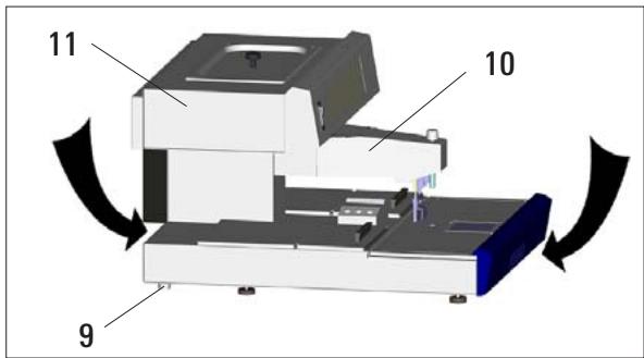
Fig. 4
4.2 Location conditions
- Stable, vibration-free laboratory table with horizontal, flat table top, as far as possible vibration-free ground.
-
The instrument must not be placed in the vicinity of the air outlet of an air conditioner and must be shielded from strong sunlight (window).
-
To ensure a fully functional heat sink, there must be gap of at least 15cm behind the instrument.
- The vicinity of the work area must be free of oil and chemical vapors.

The installation location must be well-ventilated; there should be no ignition sources there of any kind. The instrument should not be operated in hazardous locations.
4.3 Package contents
The basic equipment for the Leica EG1150 H contains the following components:
1 Leica EG1150H basic instrument
1 set of power cords for heater equipment:
1 power cord "EU" 14 0411 33613
1 power cord "UK" ST/BU F-5A 14 0411 33614
1 power cord "USA-C-J" 14 0411 33615
2 cassette/mold warmers, removable
2 lids for cassette/mold warmers
1 lid for paraffin reservoir
1 paraffin spatula 14 0388 33133
1 forceps holder, removable 14 0388 32497
1 filter screen with holder 14 0388 32208
2 paraffin collection trays 14 0388 38138
1 halogen lamp (12 V, 5 W) 14 0388 32464
1 replacement halogen lamp 5 W 14 0187 32494
1 set of spare fuses: 14 0388 46335
2 fuse T 2,0 A 6x32 14 6943 02001
2 fuse T3.2A 6x32 14694332001
2 fuse T 4.0 A 6x32 14 6943 04001
2 fuse T 6.25 A 6x32 14 6943 06251
2 fuse T 5.0 A 6x32 14 6943 05001
1 instruction manual Leica EG1150H 14 0388 80001
1 EC Declaration of Conformity Leica EG1150H 14 0388 80011

Please compare the delivered components against the packing list, delivery note, and your order. Should there be any discrepancy, please contact the Leica distributor handling your order.
4.4 Necessary assembly work
Install the following accessories and make the appropriate adjustments to make the instrument ready for use:
Install accessories.
- Adjust instrument feet if necessary.
Install magnifier (optional).
- Connect foot switch (optional).
- Establish the electrical connections.
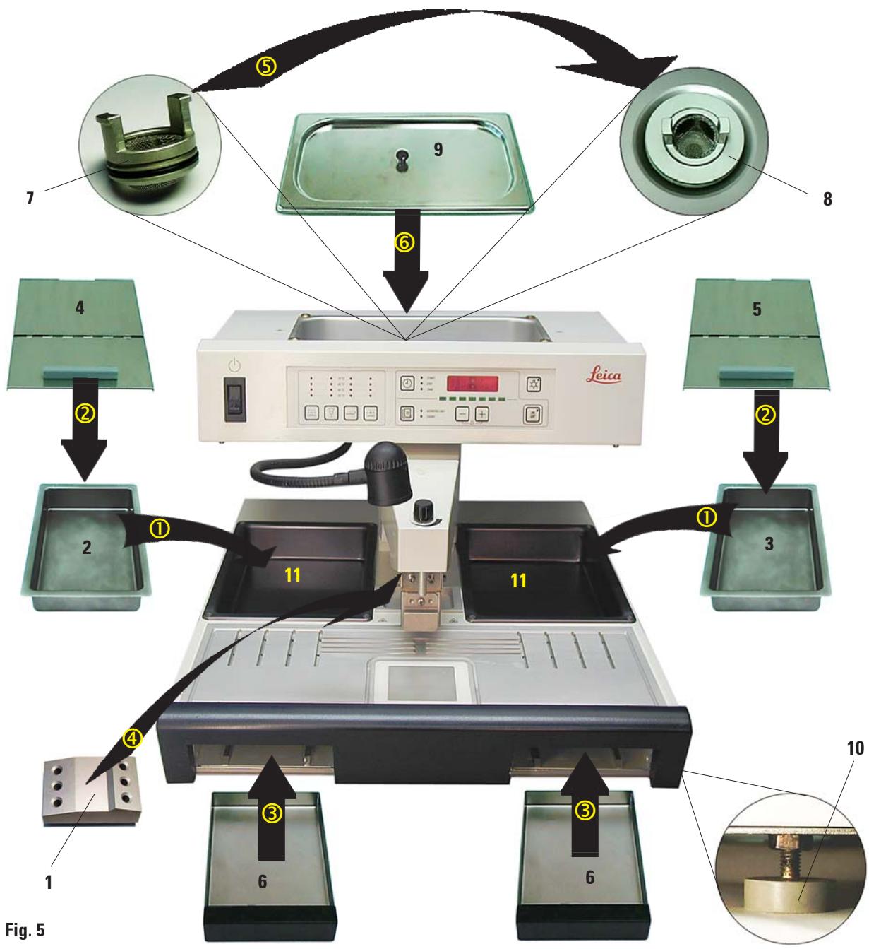
Install accessories
① Install mold warmer (2) and cassette warmer (3).
Depending on the preferred working direction, the two heated trays (11) can be used for molds or cassettes as required.
② Close mold/cassette warmer with the corresponding lids (4), (5).
③ Push the paraffin collection tray (6) into the respective guide underneath the work top.
④ Install the forceps holder (1).
⑤ Insert the filtering screen (7) in the paraffin outlet hole (8) inside the paraffin reservoir so that the black O-ring seals the hole.
⑥ Place the lid (9) on the paraffin reservoir.
Adjustable instrument feet
The four feet are height-adjustable to allow the instrument to be adjusted to match the height of other devices or to compensate slight depressions on the surface.
Lift the instrument slightly and turn the instrument foot (10 in Fig. 5) to adjust it to the proper height.

To ensure a safe stand, all of the four feet must be adjusted to the same height.
Installing the accessories
4.5 Optional accessories
Magnifying glass
The magnifying glass provides a magnified view of the work area. When properly adjusted, an enlarged view of the dispenser and refrigeration spot is available.
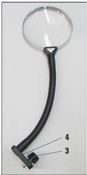
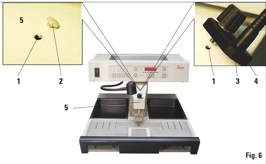
Fig. 6
Installing the magnifying glass
- On the dispenser (5) a tap hole (1) is provided, which is closed with a nylon screw (2).
- Remove the screw (2) with a screwdriver and store it in a safe place. Screw the knurled screw (3) of the stand (4) into the tap hole and align the magnifier.
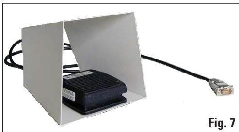
Foot switch
The foot switch can be used to actuate the dispenser valve, leaving the operator's hands free.
- To connect and use the foot switch, see Chapters 4.6 and 5.1.
4.6 Electrical connection

The instrument MUST be connected to a grounded mains socket.
The instrument is supplied with a set of different power cords. Only the power cord intended for the local power supply (socket) may be used.
Do not use an extension cord.
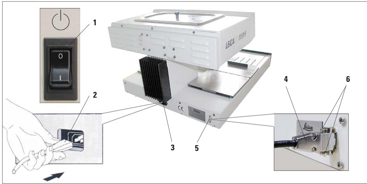
Fig. 8

Before connecting the power cord to the foot switch, ensure that the standby switch (1) (control panel, front) is set to '0' ('0' = OFF).
Connecting the power cord
- Connect the plug (2) of the power cord to the connecting port (3).
- Plug the power cord into the wall outlet.
Connecting the foot switch (optional)
- Insert the plug (4) of the foot switch into the connecting port (5) on the rear of the instrument.
- Tighten the screws (6) of the plug.
5.1 Instrument parts/functions
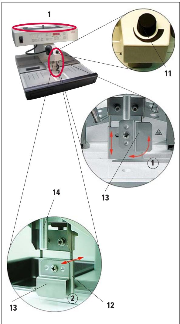
Fig. 9

The flow cannot be stopped completely with the metering screw (11). It must not be turned whilst cold!
Paraffin reservoir (1)
The paraffin reservoir has a capacity of 3 liters. The paraffin temperature is adjustable between 55^ and 70^ in 5 degree (K) increments. The lid should always be in place, otherwise the adjusted temperature cannot be maintained.
An overtemperature cutout is provided to prevent overheating the paraffin if temperature control fails.
A built-in filtering screen prevents any particles contained in the paraffin from getting in the paraffin block.

Recycled paraffin may not be used in the Leica EG1150H due to the danger of contamination.
Dispenser (2)
The dispenser is heated separately. The temperature adjustment of the dispenser and paraffin reservoir is coupled.
The quantity of paraffin released from the filler tube (14) can be adjusted continuously with the metering screw (11).
The dispenser handle (12) is used for manually operating the paraffin flow. It is provided with an extension clip (13). The extension clip is height-adjustable and can be shifted to the side (left or right) depending whether the dispenser handle is released with the mold or the finger ①.
The dispenser handle can be operated by simply pushing the mold (or the finger) against the extension clip. Slightly pushing the handle backwards will open the dispenser valve ②. Once released, the handle flips back in the original position and the valve shuts.
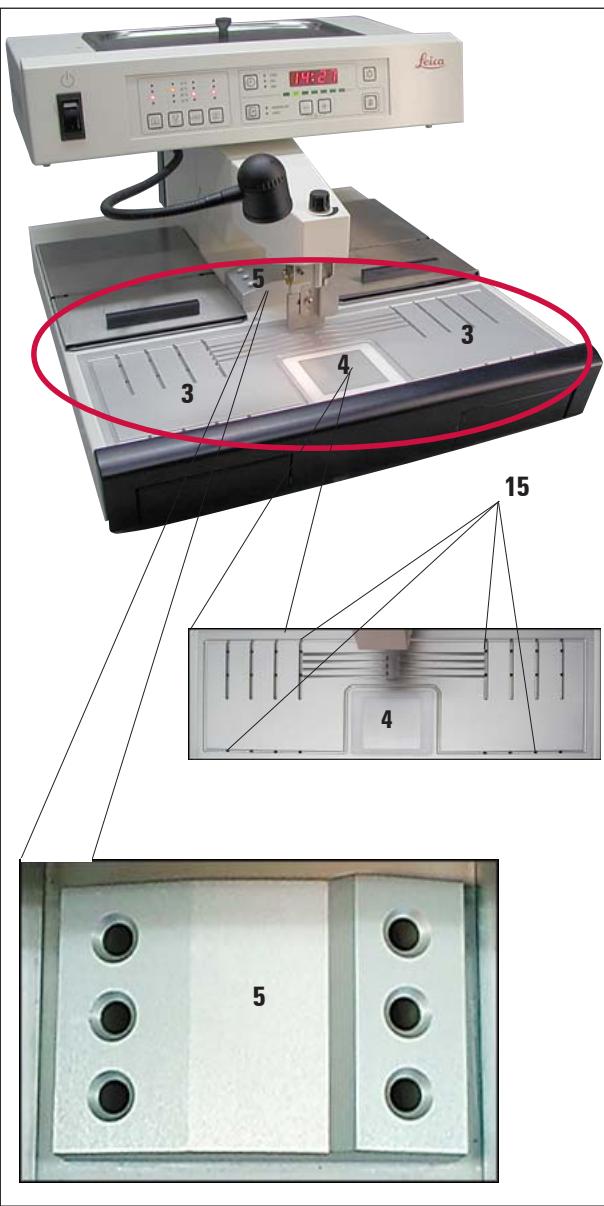
Fig. 10

The forceps holder is separately heated to approximately 70^ . Risk of burning!
Work area (3)
The temperature of the work area can be adjusted between 55^ and 70^ in 5 degree (K) increments.
This includes the embedding area, forceps holder (5) and the refrigeration spot (4).
A groove around the work area and several drain holes (15) are provided to allow liquid paraffin to drain rapidly.
Refrigeration spot (4)
The refrigeration spot is an integral part of the work area. Its position directly in front of the embedding area enables convenient working in economically most favorable conditions.
To orientate the samples, the mold is filled about one third with liquid paraffin. The liquid paraffin begins to solidify rapidly on the refrigeration spot.
While the paraffin is semi-liquid, the sample can be oriented as required. Finally, the mold can rapidly be filled up with paraffin.

While orienting the tissue, the paraffin should not become too solid, as this may cause different phases in the finished block, including fissures inside, as a result of which the block may break during sectioning.
Forceps holder (5)
The removable forceps holder under the dispenser can accommodate up to 6 forceps.
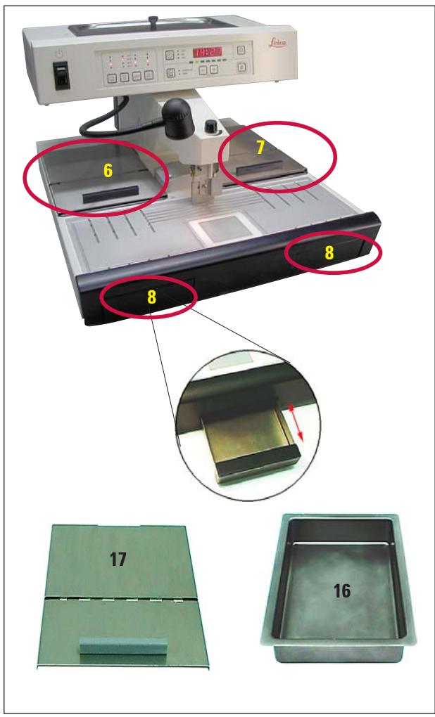
Fig. 11

When working with half-open lids (17), raise the temperature one level to ensure that the paraffin remains molten.
Paraffin collection tray (8)
Two indirectly-heated paraffin collection trays for excess paraffin are located under the work surface.

The paraffin collection tray must be emptied daily. To prevent contamination, do not reuse paraffin collected in this tray. If the instrument is operated without the paraffin collection trays there is risk of burning.
Mold warmer and cassette warmer (16)
Depending on the preferred working direction, the two heated trays can be used for molds or cassettes (6,7). The temperature is adjustable between 55^ and 70^ .
A removable receptacle (16) can be placed in each of the trays.
Each receptacle can hold approx. 100 cassettes or approx. 50 molds.
A lid (17) is provided for each of the trays (16) to prevent loss of heat and contamination inside the tray. For easy access, the lid can be opened and folded back.

Only operate the cassette and mold warmer and paraffin reservoir with lid; otherwise the set temperature cannot be maintained.
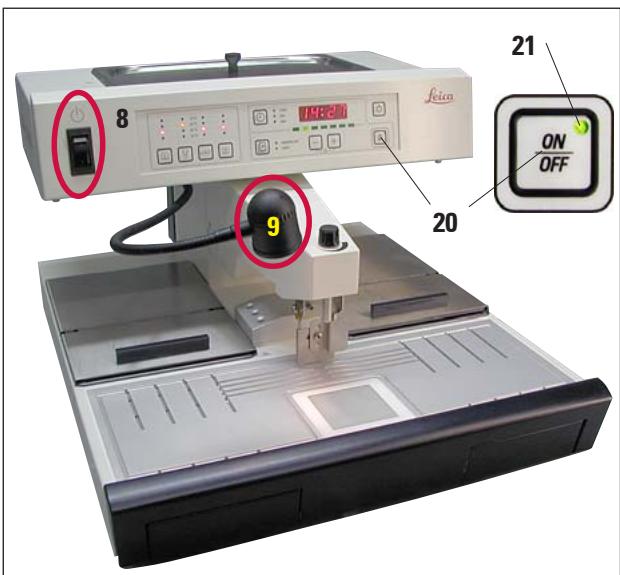
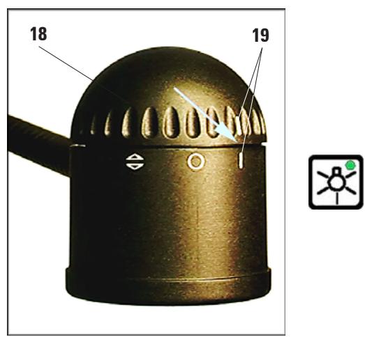
Fig. 12
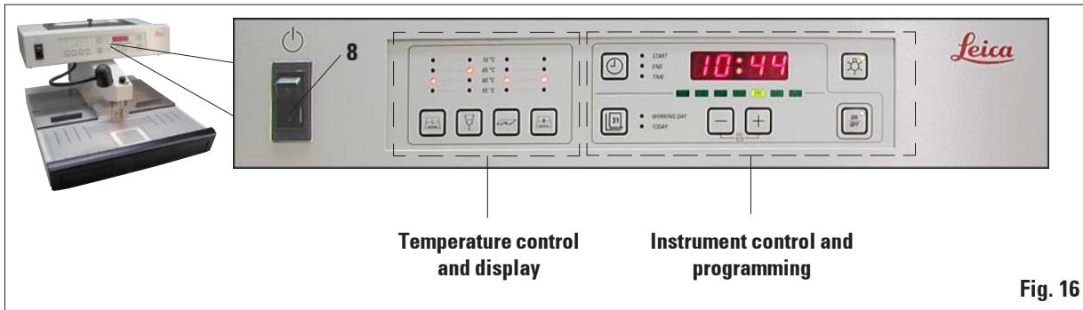
Standby switch (8)
After the unit has been commissioned, the standby switch should only be used if the unit is to be switched off for a longer period of time.
In daily routine operation, the ON/OFF button on the control panel should be used.
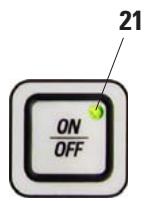
Pressing the ON/OFF button (20) switches the instrument into active standby mode.
All displays are switched off, only the LED (21) of the ON/OFF button remains lit.

If programmed procedures are to be carried out: the standby switch (8) must be switched on and the unit must be in standby mode.
For more information, see Chapter 5.4.
Work area illumination (9)
A halogen lamp provides homogeneous diffuse illumination of the embedding area and refrigeration spot. This gives an optimum view of the embedding process and tissue orientation.
The lamp should be adjusted in a way that it is switched on and off only with the lamp button on the control panel. For this purpose, turn the cap (18) in the position where the two "I" "I" marks (19) are located one above the other.
To access the halogen bulb, the cap (18) can be removed.
(For replacement of the halogen lamp see Chapter 7.2)
Foot switch (22) optional
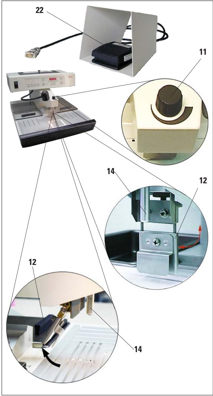
Fig. 13
The foot switch (22) actuates the magnet valve of the dispenser.
It must be connected as described in Chapter 4.6.

The plug of the foot switch MUST be screwed onto the socket. Otherwise hot paraffin may escape even when the foot switched is not being pressed.
Pressing the foot switch opens the valve, releasing it closes it. This keeps the operator's hands free to work with the instrument.
The flow volume can be adjusted with the metering screw (11).
The dispenser handle (12) is not required when using the foot switch and can be folded upwards.
Proceed as follows:
- Set the metering screw (11) to minimum.
- Carefully fold the dispenser handle (12) back/up with your thumb and index finger.

Take care when folding back the dispenser handle! Hot paraffin may come out of the filler tube (14).
DANGER OF BURNS!
5.2 Switching the instrument on
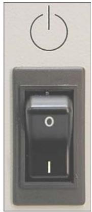
Fig. 14
- Activate the standby switch (left-hand side, next to control panel) (see Figs. 14, 16).
- All LEDs of the operating panel light up briefly and the installed software version is shown on the display for around 2 seconds.
All displays go out, the unit changes to standby mode.
The green LED in the ON/OFF button indicates that the instrument is ready to operate.

- Press the ON/OFF button down for approx. 2 seconds to switch over to the operating mode. The time indicator flashes on the display, indicating that the instrument has been disconnected from the mains supply.
Press any key to acknowledge.

The unit's normal operating mode is STANDBY/ON; i.e. switch on/off with the ON/OFF key only.
Use the standby switch only if the device is to be switched off for an extended period.
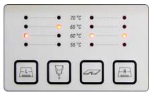
Fig. 15
- The heaters become active and the LEDs indicate the values last set.
The LED's which indicate the set temperatures of the heated areas (1, 3 and 4, fig. 17) will flash from time to time over the entire length of the heating phase (compare "Indication of the heating intervals").
The LED of the paraffin reservoir (2, fig. 17) flashes in time intervals of 1 second each while the intensified heating of the paraffin reservoir is active (4 hours).
If temperature settings are modified during the heating phase, the instrument will store the new settings and the heating phase will then correspondingly take longer.
- Fill the paraffin reservoir with paraffin.

Prior to leaving the factory, the Leica EG1150H is tested thoroughly under laboratory conditions. For this reason, you will find a small quantity of clean, hardened "Leica Histowax" in the instrument. You can work with this paraffin without any problem.
5.3 Control panel functions
The control panel beside the standby switch (8) consists of a foil keyboard with push buttons, LEDs and a single-line display.
It is divided into two control areas:
temperature setting and display and instrument control and programming.
5.4 Operating modes
Standby mode
The display and all LEDs are switched off in standby mode. The unit switches on or off automatically at the programmed start and ending times.
Only the green LED (21) in the ON/OFF button indicates that the instrument is ready to operate.
Enabling operating mode
- Hold down the ON/OFF button for approx. 2 seconds.
- The instrument switches from standby mode to operating mode. The LEDs of the currently selected values are illuminated, the display reads the current time.

The time in the display flashes when switching to operating mode if the device was disconnected from AC power for an extended period ( >5 min).
Acknowledge the flashing display by pressing any button and check whether all required heating phases (especially the paraffin reservoir) are complete.
24-hour mode - working in shift mode
If the switch-on and switch off times of the timer are set to the same value, the instrument will run continuously, even on days that are not defined as work days.
Example: switch-on time = 00 : 00 and switch-off time = 00 : 00 .
To set the timer, see Chapter 5.5.

Important The timer is disabled if the switch-off time is before the switch-on time.
E.g. switch-on time: 08:00 a.m. and switch-off time: 06:00 a.m.

In 24-hour mode, activate enhanced mode (see Chap. 5.6) to accelerate the melting process after replenishing solid paraffin.
5.5 Time-program control
The value shown in the display must be set to the current local time to ensure the correct operation of the time-program control.

Setting the time
- Press the CLOCK button as many times as required until the green "TIME" LED lights up.
- Set the current time with the + / - buttons. The required value is reached faster when holding down the button in question.
Start time
The start time is the time at which the instrument automatically switches from standby to operating mode.
Setting the start-of-work and end-of-work times:
- Press the CLOCK button as many times as required until the green LED "START" lights up.
- Set the start time with the + / - buttons. The required value is reached faster when holding down the button in question.
End time
Automatic switch-over of the unit from operating to standby mode takes place at the set ending time.
Setting the start-of-work and end-of-work times:
- Press the CLOCK button as many times as required until the green "END" LED lights up. Set the time as described above.

All set times are stored - even if the unit is switched off with the standby switch - until they are changed.
Weekdays/working days
The automatic switch-on feature is linked with the individual weekdays. It is therefore necessary to define the days for which the automatic switch-on feature shall operate.

Only on those weekdays that have been defined as working days, the instrument will be at the required temperature and ready to operate.
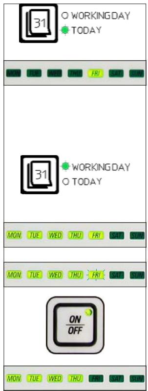
Fig. 19
Setting the current weekday:
- Press the DAY button as many times as required until the green "TODAY" LED lights up. The green LED of the current weekday is illuminated.
- If necessary, set the current day with the - buttons - the associated LED lights up.
Defining the working days:
- Press the DAY button as many times as required until the green LED "WORKING DAY" lights up. The LEDs of the weekdays defined as working days light up, while the LED of the current day flashes.
- Use the - / + buttons to select the day to be defined or canceled as working day.
The LED of the selected day (FRI) flashes.
- Press the ON/OFF button.
If that day had not been a working day (LED off), it will now be added to the working day list (LED on).
Otherwise (see Fig. 19, FRI was defined as a working day, LED on), the day will no longer be defined as a working day (LED off).

If the programmed values are to be effective on the following days (the instrument is operational at the programmed time and switches off automatically when the switch-off time is reached), the standby mode must be active --> press ON/OFF.
5.6 Instrument heater
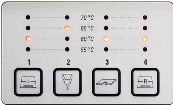
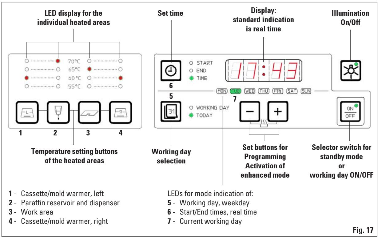
Fig. 20
1 - Cassette/mold warmer, left
2 - Paraffin reservoirdispenser
3 - Temperature of work area
4 - Cassette/mold warmer, right
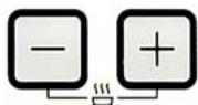
Setting temperature values
The temperatures for the four heated areas can be adjusted separately in a range from 55^ to 70^ in 5 degree (K) increments.

When setting the temperature, please observe the paraffin manufacturer's specifications for the maximum permissible temperature.
Press the buttons for the temperature range once to increase the value by 5K . The red LED for the associated temperature value will light up - after 70^ has been reached, the temperature will revert to 55^ .
Once set, the temperature value for one range will be retained until it is changed.
Indication of the heating intervals
In the temperature range indication field, the LED for the temperature selected at a time will always light. While heating for the area in question is active, the LED flashes as long as heating continues.
It is possible to deactivate the indication (= flashing) of the heating activity.
Proceed as follows:
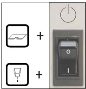
Fig. 21
- Switch off the instrument with the standby switch (①, not ON/OFF).
- Hold down the WORK AREA button and switch the instrument on again with the standby switch.
- To return to the "flashing" mode, switch off the instrument with standby switch as described under 1.
Hold down the PARAFFIN DISPENSER button when switching back on.
Advance times
To ensure that the instrument is ready (all working temperatures reached) at the programmed start time, the various sections are activated in advance as follows:
Paraffin reservoir: heating starts 4 hours before work starts.
Work area: heating starts 4 hours before work starts.
Dispenser tube: heating starts 1 hour before work starts.
Refrigeration spot: refrigeration begins 1 hour before work starts.
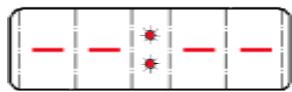
Display
During the heating phase, the display reads - - : - - ; the colon flashes in intervals of seconds.
The advance times cannot be modified.
Enhanced mode
A large amount of heat is needed for melting paraffin. This is only accounted for in standby mode for a respective preliminary time. In the operating mode, the paraffin reservoir is heated just enough to maintain the paraffin at the selected temperature. Therefore the melting process can be sped up by increasing the heat supply (enhanced mode) whenever necessary (e.g. when solid paraffin has to be added to the reservoir when working in shifts). The paraffin reservoir is then heated for a period of four hours to a higher temperature (enhanced mode).
press simultaneously
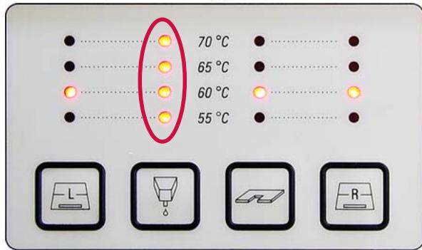
Fig. 22
To activate the enhanced mode, push and hold the + and - buttons simultaneously until all four set value LED's of the paraffin reservoir light up for an instant indicating thus that the enhanced mode has been activated.
The selected set value LED flashes while enhanced mode is enabled.
The enhanced mode can be switched off at any time by pressing and holding and again until all four LED's of the paraffin reservoir light up briefly indicating that the enhanced mode has been switched off.
6.1 Cleaning the instrument

Do not use xylene for cleaning. Xylene vapors are heavier than air and can ignite at a considerable distance from the source of heat.
Fire hazard!
To avoid scratching the surface of the instrument only the plastic spatula that is supplied with it should be used for cleaning – on no account metal tools!
Work area
- All common laboratory cleaning products suitable for the removal of paraffin (e.g. Paraguard or xylene substitutes) can be used to clean the work area.
- Avoid prolonged contact of organic solvents on the surface of the instrument.
Paraffin reservoir
- Keep contaminants out of the paraffin reservoir.
- Ensure that a residual amount of paraffin remains in the reservoir after draining to prevent solid contaminants from entering the dispenser.
- Absorb this paraffin with tissue or a paper towel. Do not remove the screen until the residual paraffin has been removed.
- The interior surfaces of the reservoir can then be cleaned with a tissue.
Forceps holder
- The forceps holder is often a source of contamination and extremely susceptible to dirt. Therefore, clean the forceps holder thoroughly.

Important!
The forceps holder is separately heated to approximately 70^ . Risk of burning!
Paraffin collection tray
- Before the paraffin collection tray drawers can be emptied, any excess paraffin on the work area must be removed with cellulose wadding in order to prevent any paraffin from penetrating into the instrument.

Use care with paraffins with a low melting point - risk of burning when removing the paraffin collection trays due to liquid paraffin.
- Only remove and empty the paraffin collection trays while they are warm.
- The paraffin in the collection trays must not be reused. Danger of paraffin carry-over into the instrument.
- Empty both paraffin collection trays regularly in order to prevent them from overflowing into the instrument. While emptying intervals may vary depending on use, the trays should be emptied at least daily.

If the paraffin collection trays are not emptied regularly, excess paraffin may flow into the instrument or onto the work surface.
In addition to the risk of burns, this may damage the instrument.
6.2 Maintenance instructions

Only Leica service technicians are authorized to open the instrument for maintenance and repair work.
The Leica EG1150H is virtually maintenance-free.
Please observe the following points to ensure the instrument's reliable function over extended periods:
- Clean the instrument daily with care.
- Regularly remove dust from the ventilation slots on the back of the instrument with a brush or vacuum cleaner.
- Have the instrument inspected at least once a year by an authorized Leica customer service technician.
- Enter into a service contract at the end of the warranty period. For more information, contact the relevant technical service center.
7.1 Possible faults
This chapter will help to correct problems that may occur when working with the Leica EG1150H.
If a problem cannot be remedied by following the instructions in this chapter, please contact your Leica technical service center.
For further instructions, please refer to Chapter 8.
The table below includes the most common problems that may occur when working with the instrument, including possible causes and corrective action.
Problem
Possible cause
Corrective action
1. Display
On the display the

is shown.
The colon flashes.
The instrument is in the heating phase (standby mode)
- This is not an error message!
The instrument will switch to the program mode at the preselected time.
2. Instrument does not switch on
- Standby switch not turned on
- or
- cut-out function of the standby switch activated.
-
ON/OFF button not pressed long enough.
-
Standby switch ON.
- Check unit connection, then turn standby switch ON.
Hold down ON/OFF button for several seconds (at least 2 secs).
| Problem | Possible cause | Corrective action |
| 3. Paraffin reservoir | ||
| Paraffin does not melt or melts only very slowly. | - Selected temperature too low. | - Increase temperature for paraffin reservoir. |
| - No enhanced mode set. | - Activate enhanced mode. (see Chapter 5.6) | |
| - Temperature indication incorrect, or no heating of paraffin reservoir. | - Check temperature settings and repeat if necessary. | |
| - Start-of-work time selec-tion incorrect. | - Check start-of-work time. | |
| - Fuse for the heater of the paraffin reservoir activated. | - Check fuses and replace as required (see Chapter 7.3) | |
| - Instrument malfunction | - Contact customer service. | |
| 4. Paraffin dispenser | ||
| No paraffin flow. | - Paraffin not completely molten. | - Wait until paraffin is en-tirely molten; then check again. |
| Paraffin drops when valve is shut. | - The paraffin outlet is clogged or the magnetic switch defective. | - Contact customer service. |
| Non-homogeneous paraffin flow (e.g. air pockets). | - Air pockets in dispenser at the start. | - Keep dispenser open at maximum flow for a period of time. |
7. Troubleshooting
| Problem | Possible cause | Corrective action |
| 5. Illumination does not work. | - Cap of the work area halogen lamp incorrectly positioned. | - Check adjustment of lamp cap. (see Figures 12 / 23) |
| - Bulb defective. | - Replace bulb (see Chapter 7.2) | |
| - Fuse defective. | - Replace fuse (see Chapter 7.3) | |
| 6. Individual heated areas (despite correct temperature indication) heating does not work. | - Fuse for this heated area has responded. | - Replace fuse. (see Chapter 7.3) |
| - Heater defective. | - Contact customer service. | |
| 7. Error message in display On the display the indication is shown. Program and time are lost. | - The battery is empty and also | - Acknowledge error with any key and continue working after reprogramming. |
| - Power failure or Device switched off with standby switch or Mains plug pulled. | Ask technical service to replace battery. |
7.2 Replacing the halogen lamp
Only use the original replacement lamp delivered with the maintenance kit.

Before you replace the lamp, switch off the unit at the standby switch and disconnect the mains plug.
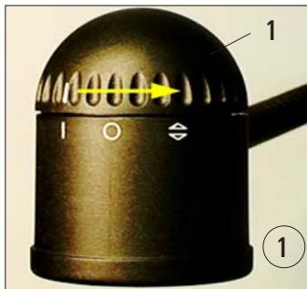
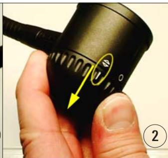
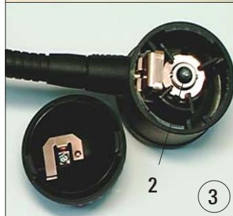
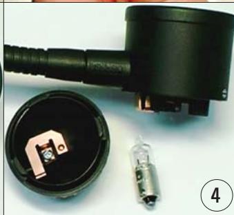
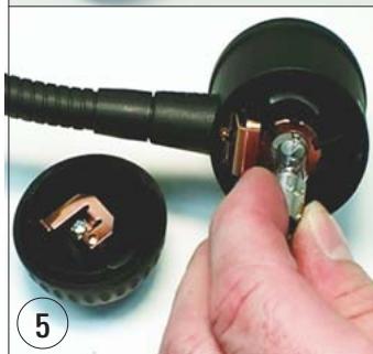
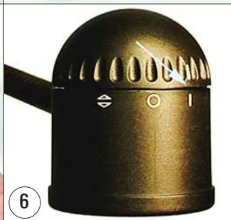
Fig. 23
To replace the halogen lamp, please proceed as shown in Fig. 23:
- Turn the upper, moveable cap on the lamp (1) until the markings are in alignment as shown in the figure. ①
- Remove cap – this can be done only in the position shown in ②.
- Pull out defective lamp (2). ③ If this cannot be done by hand, do not use any hard or acute tools (e.g. screwdriver). Wait until the lamp has cooled down. Turn lamp housing upside down and lightly knock on the housing until the lamp falls out. ④
- Hold the new lamp with care (do not touch the glass bulb!) and insert in the housing. ⑤
- Replace cap (observing correct alignment!) and turn to the "I" to "I" position. ⑥
7.3 Changing a fuse

Before changing a fuse switch the instrument off and pull out the mains plug.
Use ONLY the provided replacement fuses.
Important!
The instrument has a number of circuits that are protected by fuses with different values.
Observe the following instructions exactly to ensure that the correct spare fuse is used for the matching fuse holder.
The instrument has five electrical areas with separate secondary fuse protection. The secondary fuses are located in individual fuse inserts at the back of the instrument.
The secondary fuses are secured with two metal plates (6,7) that must be removed first.
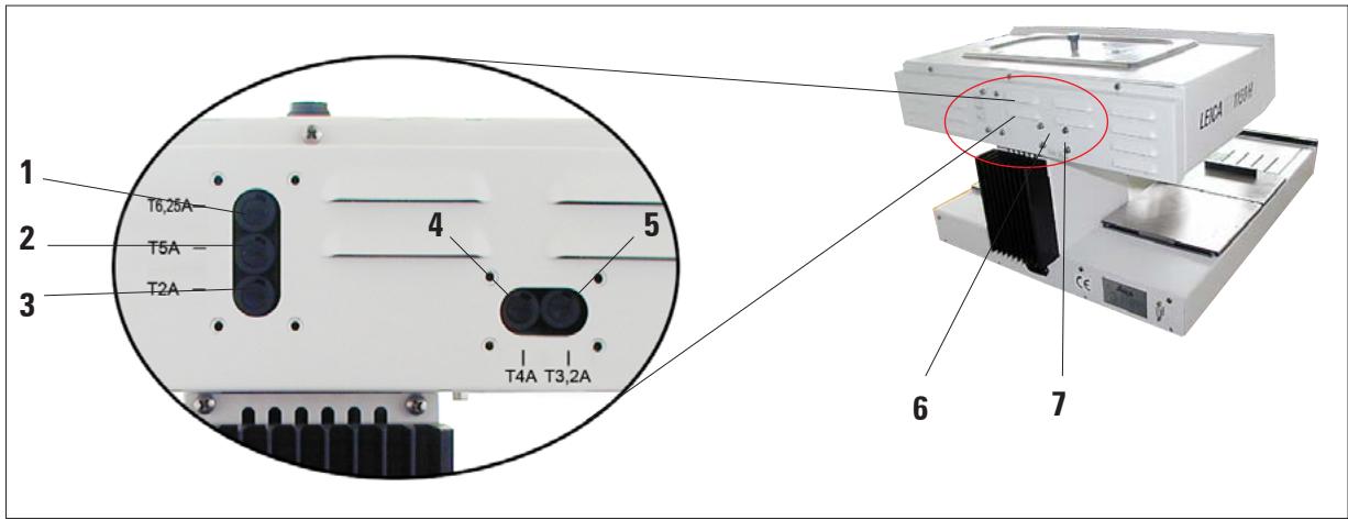
Fig. 24
The individual fuses apply to the following areas:
1 - Peltier element of the refrigeration spot and work area illumination.
2 - Heating for forceps holder and paraffin dispenser.
3 - Electronics.
4 - Heating for work area and cassette warmer right.
5 - Heating for paraffin reservoir and cassette warmer left.
Select the correct spare fuse
This marking (2A) on the fuse and the labeling next to the fuse holder on the rear of the instrument MUST agree!
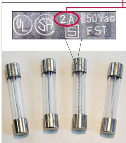
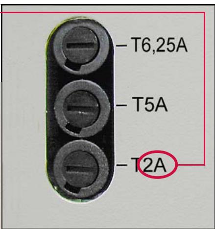
Fig. 25
On the back there are five different fuse holders (Fig. 24).
One spare fuse must be selected from the five spare fuses available that has the marking 2A written on it.
(see Fig. 25, left)
Only the spare fuse with the marking 2A may be inserted in this fuse holder (T2A).
This is also applicable in the same way for the other fuse holders.
The metal caps on the spare fuses are labeled – the labeling looks similar to that shown in the figure above, but can vary depending on the type of fuse.
The label information which is important for the correct use of the fuse is its maximum current (in the marked example: T2A).
Change fuse
Using a screwdriver (8) lightly press in the fuse holder (9) and then turn anti-clockwise one 1/4 turn and let go.
The fuse holder is pressed out and can be removed.
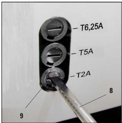
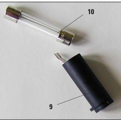
Fig. 26
Take the defective fuse (10) out of the fuse holder (9) and replace it by the selected spare fuse.
Insert the fuse holder with the spare fuse, press in using screwdriver (1) and secure by turning it clockwise 1/4 turn.
Replace fuse cover (6,7).
Warranty
Leica Biosystems Nussloch GmbH guarantees that the contractual product delivered has been subjected to a comprehensive quality control procedure based on the Leica in-house testing standards, and that the product is faultless and complies with all technical specifications and/or agreed characteristics warranted.
The scope of the warranty is based on the content of the concluded agreement. The warranty terms of your Leica sales organization or the organization from which you have purchased the contractual product shall apply exclusively.
Technical service information
If you require technical service or replacement parts, please contact your Leica sales representative or dealer who sold the product.
Please provide the following information:
- Model name and serial number of the instrument.
- Location of the instrument and name of the person to contact.
- Reason for the service call.
- Date of delivery.
Decommissioning and disposal
The instrument or parts of the instrument must be disposed of in compliance with the local laws.
- Paraffin Embedding Station
- Instruction Manual
- Symbols used in the text and their meanings
- Specified use and application
- User group
- Instrument type
- Safety notes
- 2.2Warnings
- Safety instructions - safety regulations on the instrument itself
- Safety instructions - transport and installation
- Safety instructions - working with the instrument
- Hazards - servicing and cleaning
- Built-in safety devices
- Fuses in the heating elements
- Automatic circuit breaker in standby switch
- Specifications
- General data
- Fuses
- Dimensions and weight
- Capacities
- Programmable parameters
- Overview - instrument parts
- Instrument specifications
- Unpacking and installation
- Location conditions
- Package contents
- Necessary assembly work
- Install accessories
- Adjustable instrument feet
- Optional accessories
- Magnifying glass
- Installing the magnifying glass
- Foot switch
- Electrical connection
- Connecting the power cord
- Connecting the foot switch (optional)
- Instrument parts/functions
- Paraffin reservoir (1)
- Dispenser (2)
- Work area (3)
- Refrigeration spot (4)
- Forceps holder (5)
- Paraffin collection tray (8)
- Mold warmer and cassette warmer (16)
- Standby switch (8)
- Work area illumination (9)
- Foot switch (22) optional
- Switching the instrument on
- Control panel functions
- Operating modes
- Standby mode
- Enabling operating mode
- 24-hour mode - working in shift mode
- Time-program control
- Setting the time
- Start time
- Setting the start-of-work and end-of-work times:
- End time
- Weekdays/working days
- Setting the current weekday:
- Defining the working days:
- Instrument heater
- Setting temperature values
- Indication of the heating intervals
- Advance times
- Enhanced mode
- Cleaning the instrument
- Work area
- Paraffin reservoir
- Forceps holder
- Paraffin collection tray
- Maintenance instructions
- Possible faults
- Problem
- Possible cause
- Corrective action
- Display
- Instrument does not switch on
- Troubleshooting
- Replacing the halogen lamp
- Changing a fuse
- The individual fuses apply to the following areas:
- Select the correct spare fuse
- Change fuse
- Warranty
- Technical service information
- Decommissioning and disposal
Brand : LEICA
Model : EG 1150 H
Category : Microtome