
ECO - Heat pump water heater REGENT - Free user manual and instructions
Find the device manual for free ECO REGENT in PDF.
User questions about ECO REGENT
0 question about this device. Answer the ones you know or ask your own.
Ask a new question about this device
Download the instructions for your Heat pump water heater in PDF format for free! Find your manual ECO - REGENT and take your electronic device back in hand. On this page are published all the documents necessary for the use of your device. ECO by REGENT.
USER MANUAL ECO REGENT
1.4 Certifications - Marquage CE
4.4 Raccordement hydraulique
We wish to thank you for having purchased the heat pump water heater. We hope that it meets your expectations and may offer you optimal service coupled with maximum energy saving for many years to come.
Our group invests a lot of time, energy and economic resources in creating innovative solutions aimed at reducing the energy consumption of its products.
Your choice shows sensibility and awareness towards reducing energy consumption, an issue directly related to environmental protection. Our constant commitment to creating innovative and efficient products coupled with your responsible behaviour in the rational use of energy both actively contribute to safeguarding the environment and natural resources.
Store this manual with care; it is intended to provide information, warnings and suggestions on the correct use and maintenance of the appliance, so that you may fully appreciate all its qualities. Our technical assistance centre closest to you is at your complete disposal for answering any of your queries.
INTRODUCTION
This manual is intended for final users of the heat pump water heater and plumbers responsible for the latter's installation. Failure to observe the indications contained in this manual shall void the warranty.
This manual is an integral and essential part of the appliance. It must be stored with care by the user and should always be passed on to new owners or users of the appliance, and/or when the latter is transferred to another system.
In order to ensure correct and safe use of the appliance, both installer and user, each for his/her respective requirements, must read the instructions and precautions contained in this manual carefully, as they provide important safety indications concerning installation, use and maintenance of the appliance.
This manual is divided into three distinct sections:
GENERAL INFORMATION
This section contains useful general information relating to the description of the appliance and its technical features, besides information on the symbols, units of measurement and technical terms used. This section includes the water heater's technical data and dimensions.
- TECHNICAL INFORMATION FOR INSTALLERS
This section is intended for installers. It contains all the indications and instructions that professionally qualified personnel must observe in order to ensure optimal installation of the appliance.
OPERATING AND MAINTENANCE INSTRUCTIONS FOR THE USER
This section is intended for final users and contains all the information necessary for operating the appliance correctly and for assisting the user in carrying out regular checks and maintenance operations on the appliance.
The manufacturer reserves the right to modify the data and contents of this manual without prior notice, with the aim of improving the quality of the relative products.
To facilitate understanding of the contents herein, given that the manual is published in multiple languages and is valid for use in several
countries, all the illustrations are grouped in the final pages and are common to the various languages.
TABLE OF CONTENTS
GENERAL INFORMATION
| 1. | GENERAL INFORMATION |
| 1.1 Description of the symbols used | |
| 1.2 | Field of application |
| 1.3 | Instructions and technical norms |
| 1.4 | Certifications – CE marking |
| 1.5 | Packaging and supplied accessories |
| 1.6 | Transport and handling |
| 1.7 | Identification of the appliance |
| 2. | TECHNICAL FEATURES |
| 2.1 | Operating principle |
| 2.2 | Construction features |
| 2.3 | Overall dimensions |
| 2.4 | Electrical diagram |
| 2.5 | Technical data table |
| TECHNICAL INFORMATION FOR INSTALLERS | |
| 3. | WARNING |
| 3.1 | Installer qualification |
| 3.2 | Implementing the instructions |
| 3.3 | Safety regulations |
| 4. | INSTALLATION |
| 4.1 | Location of the appliance |
| 4.2 | Positioning on the ground |
| 4.3 | Air supply connections |
| 4.4 | Hydraulic connections |
| 4.5 | Electrical connections |
| 4.6 | Initial start-up |
| 5. | MAINTENANCE REGULATIONS (for authorised personnel) |
| 5.1 | Emptying the appliance |
| 5.2 | Routine maintenance |
| 5.3 | Useful information |
| OPERATING AND MAINTENANCE INSTRUCTIONS FOR THE USER | |
| 6. | WARNING |
| 6.1 | Initial start-up |
| 6.2 | Recommendations |
| 6.3 | Safety regulations |
| 7. | INSTRUCTIONS FOR USE |
| 7.1 | Control panel description |
| 7.2 | Turning the water heater on/off |
| 7.3 | Setting the temperature |
| 7.4 | Mode of operation |
| 7.5 | Information menu |
| 7.6 | Installer menu |
| 7.7 | Anti-legionnaire's disease protection |
| 7.8 | Default settings |
| 7.9 | Operation with two-tier electricity rate |
| 7.10 | Faults |
| 8. | MAINTENANCE |
| 8.1 | Routine maintenance performed by users |
| 8.2 | Water heater disposal |
| ILLUSTRATIONS | |
GENERAL INFORMATION
1.1 Description of the symbols used
In terms of installation and operation safety, the symbols described in the table below are used in order to stress the importance of the relative risk warnings:
| Symbol | Description |
| ! | Failure to comply with this warning may result in injury to persons or, in some cases, death. |
| △ | Failure to comply with this warning may result in serious damage to property and plants or injury to animals. |
| ◎ | It is mandatory to comply with the general and appliance-specific safety measures. |
1.2 Field of application
This appliance is intended for hot water production for domestic use or similar, at temperatures below boiling point. The appliance must be hydraulically connected to a domestic water supply line and to a power supply network. Exhaust ducts may be used for the entry and discharge of processed air.
It is forbidden to use of the appliance for uses other than those specified. Any alternative use of the appliance constitutes improper use and is prohibited; in particular, the appliance may not be used in industrial cycles and/or installed in environments exposed to corrosive or explosive materials. The manufacturer shall not be held liable for any damage due to faulty installation, improper use or uses deriving from behaviour that is not reasonably predictable, and incomplete or careless implementation of the instructions contained in this manual.

This appliance should not be operated by individuals (including children) with reduced physical or sensory abilities, or by inexperienced or unskilled individuals, unless adequately supervised and trained regarding use of the appliance by persons responsible for their own safety. Children must be supervised by persons responsible for their safety so as to ensure that they do not use the appliance as a toy.
1.3 Instructions and technical norms
The purchaser pays for the appliance's installation, which must be carried out by qualified personnel only, in conformity with national regulations in force and any provisions emitted by local authorities or bodies responsible for public health, and in accordance with the specific manufacturer indications contained in this manual.
The manufacturer is responsible for the product's conformity to the relevant construction directives, laws and regulations in force at the time the product is first commercialised. The designer, installer and user are each exclusively responsible, in their respective fields, for knowing and observing the legal requirements and technical regulations concerning the design, installation, operation and maintenance of the appliance. Any reference to laws, regulations or technical specifications contained in this manual is purely for information purposes; any new laws introduced or modifications to existing laws are not in any way binding on the manufacturer towards third parties. It is necessary to ensure that the power supply network to which the product is connected complies with the EN 50160 norm (under penalty of warranty invalidation). Relative to France, ensure that installation complies with the NFC 15-100 norm.
1.3 Certifications - CE marking
The CE marking applied to the appliance certifies that the latter conforms to the essential requirements of the following European Directives:
- 2006/95/EC concerning the safety of electrical equipment.
- 2004/108/EC concerning electromagnetic compatibility.
The inspection is carried out according to the following technical standards:
EN 255-3; EN 60335-1; EN/IEC 60335-2-21; EN 60335-2-40; EN 55014-1; EN 61000-3-2; EN 61000-3-3; EN 50366
CAHIER DE CHARGE_103-15-A_11-2008 Chauffe-eau Thermodynamiques POUR LA MARQUE NF elettricité performance.
1.5 Packaging and supplied accessories
The appliance is anchored to a wooden pallet and is protected with polystyrene edge protectors, cardboard and a plastic transparent film on the outside; all the materials are recyclable and eco-compatible.
The following accessories are included:
- Belt for handling the water heater (to be removed once the product is installed).
- Connection pipe for condensation water.
- Instruction manual and warranty documents.
- One 3/4 dielectric coupling.
1.6 Transport and handling
Upon delivery of the product, check that the latter has not been damaged during transport and that no signs of damage appear on the packaging. In the event of damages, immediately notify any claims to the forwarder.
WARNING! The appliance should be handled and stored in a vertical position. The product may be handled in a horizontal position only for short distances, while resting on the rear end indicated; in this case, wait at least 3 hours before starting the appliance once it has been correctly repositioned in a vertical position and/or installed; this is to ensure that the lubricating oil inside the refrigeration circuit is suitably distributed and to avoid damages to the compressor.
The packaged appliance may be handled either manually or with the aid of a forklift truck, while ensuring that the above indications are observed. It is advisable to keep the appliance in its original packaging until installing it in its chosen location, particularly when construction work is under way on-site.
Upon removing the packaging, check whether the appliance is intact and that no parts are missing. In the event of defects or missing components, notify the dealer within the time limits specified by the law.
WARNING! Keep the packaging elements out of the reach of children, as they are potentially dangerous.
When transporting or handling the appliance after the initial start-up, observe the aforementioned indication concerning the allowed tilt angle and ensure that all water has been drained from the tank. Should the original packaging be missing, provide an adequate protection for the appliance to prevent any damages, for which the manufacturer shall not be held liable.
| Allowed positions | Non-allowed positions |
1.7 Identification of the appliance
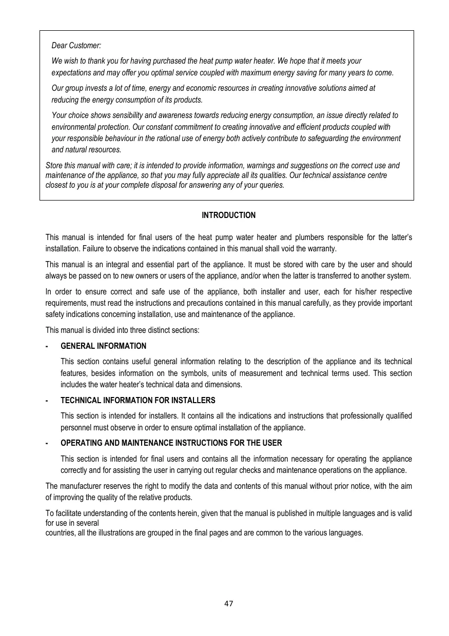
The main information for identifying the appliance is contained on the adhesive data plate located on the water heater casing.
| A | model |
| B | tank capacity |
| C | serial no. |
| D | power supply voltage. frequency. maximum absorbed power |
| E | max./min. pressure of the refrigeration circuit |
| F | tank protection |
| G | absorbed power – heating element mode |
| H | marks and symbols |
| I | thermal power yielded in heat pump mode |
| L | max./min. power in heat pump mode |
| M | type of refrigerant and charge |
| N | maximum tank pressure |
2. TECHNICAL FEATURES
2.1 Operating principle
The heat pump water heater does not directly heat water using electrical energy, but makes a more rational use of the latter to obtain the same result in a more efficient manner, namely by consuming approx. 2/3 less water.
The efficiency of a heat pump cycle is measured by the Coefficient of Performance (COP), i.e. the ratio between the energy supplied to the appliance (in this case, the heat transferred to the water to be heated) and the electrical energy used (by the compressor and the appliance's auxiliary devices). The COP varies according to the type of heat pump and to its relative conditions of operation.
For example, a COP value equal to 3 indicates that for every 1kWh of electrical energy used, the heat pump supplies 3kWh of heat to the medium to be heated, of which 2kWh are extracted from the free source.
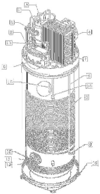
| 2.2 Construction featuresRefer to Fig. 1 | |||
| 1 | hermetic rotary compressor | ||
| 2 | electrolytic condenser for compressor | ||
| 3 | safety pressure switch | ||
| 4 | fan | ||
| 5 | thermostatic expansion valve | ||
| 6 | condenser | ||
| 7 | evaporator | ||
| 8 | electronic control panel | ||
| 9 | condensate drainage pipe | ||
| 10 | electric heating element | ||
| 11 | titanium impressed current anode | ||
| 12 | functional and safety NTC sensor | ||
| 13 | hot gas defrost valve (only on EXT models) | ||
| 14 | outlet water NTC temperature sensor | ||
| 15 | disposable magnesium anode | ||
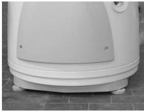
| 16 | feet with adjustable height | ||
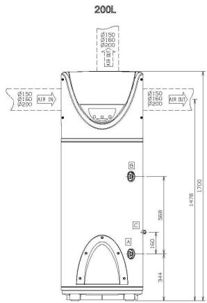
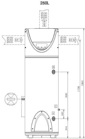
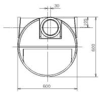
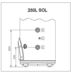
| 2.3 Overall dimensionsRefer to Fig. 2 | |||
| A | Inlet cold water 3/4" pipe | ||
| B | Outlet hot water 3/4" pipe | ||
| C | Condensate drainage connection | ||
| D | Solar circuit 3/4" inlet pipe (SOL version only) | ||
| E | Solar circuit 3/4" outlet pipe (SOL version only) | ||
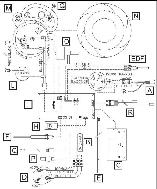
| 2.4 Electrical diagramRefer to Fig. 3 | |||
| SYMBOL | DESCRIPTION | ||
| A | Power supply | ||
| B | Batteries | ||
| C | Interface board | ||
| D | Electric heating element | ||
| E | NTC sensor for heating element zone | ||
| F | Impressed current anode | ||
| G | Water tank earth connection | ||
| H | Serial connection board | ||
| I | Mainboard | ||
| L | Operation condenser | ||
| M | Compressor | ||
| N | Fan | ||
| O | Hot gas valve | ||
| D | Safety pressure switch | ||
| Q | NTC sensor for hot water pipe zone | ||
| R | NTC sensor for evaporator and inlet air | ||
| EDF | HCHP signal (EDP) - cable not supplied with the product | ||
2.5 Technical data table
| Description | Unit of measurement | 200 EXT | 250 EXT | 250 SOL EXT | |
| Rated tank capacity | 1 | 200 | 255 | 255 | |
| Insulation thickness | mm | ≈ 50 | |||
| Type of internal tank protection | enamelling | ||||
| Type of corrosion protection | titanium impressed current anode + disposable magnesium anode | ||||
| Maximum operating pressure | MPa | 0.6 | |||
| Diameter of hydraulic connections | II | G 3/4 M | |||
| Diameter of condensate drainage connection | mm | 1/2 F | |||
| Diameter of air exhaust/intake pipes | mm | 150-160-200 | |||
| Minimum water hardness | °F | 12 | |||
| Weight when empty | kg | 90 | 95 | 110 | |
| Qpr (over 24h) | kWh | 0.6 | 0.63 | 0.63 | |
| Solar heating circuit exchange surface | m² | - | - | 0.65 | |
| Heat pump | |||||
| Heat rating (*) | W | 2775 | 2775 | 2775 | |
| Average electrical power consumption (*) | W | 750 | 750 | 750 | |
| Max. electrical power consumption (*) | W | 950 | 950 | 950 | |
| COP (*) | 3.7 | 3.7 | 3.7 | ||
| Heating time (*) | h.min | 3:10 | 3:41 | 3:41 | |
| Heating energy consumption (*) | kWh | 2.2 | 2.7 | 2.7 | |
| Max. amount of hot water in a single intake V40(**) | delivered at 55°C | 1 | 260 | 325 | 325 |
| delivered at 62°C | 1 | 348 | 435 | 435 | |
| Max. water temperature with heat pump | °C | 62 (55 factory default setting) | 62 (55 factory default setting) | 62 (55 factory default setting) | |
| Quantity of R134a refrigerant fluid | kg | 1.28 | 1.28 | 1.28 | |
| Max. pressure of refrigerating circuit (low-pressure side) | MPa | 1 | 1 | 1 | |
| Max. pressure of refrigerating circuit (high-pressure side) | MPa | 2.4 | 2.4 | 2.4 | |
| Heating element | ||||
| Heating element power | W | 1500+1000 | 1500+1000 | 1500+1000 |
| Max. water temperature with heating element | °C | 75 (65 factory default setting) | 75 (65 factory default setting) | 75 (65 factory default setting) |
| Max. current consumption | A | 10.8 | 10.8 | 10.8 |
Heat pump water heater - GENERAL INFORMATION
| Description | Unit of measurement | 200 EXT | 250 EXT | 250 SOL EXT |
| Power supply | ||||
| Voltage / max. power consumption (+) | V / W | 220-230 single-phase / 2500 | ||
| Frequency | Hz | 50 | ||
| Protection rating | IPX4 | |||
| Air side | ||||
| Standard air flow rate (automatic modulating control) | m³/h | 300-500 | 300-500 | 300-500 |
| Available static pressure | Pa | 70 | 70 | 70 |
| Sound power | dB(A) | 56 | 56 | 56 |
| Level of sound pressure at 2 m | dB(A) | 39 | 39 | 39 |
| Minimum volume of room of installation (***) | m³ | 20 | 20 | 20 |
| Minimum ceiling height of room of installation | m | 1.75 | 2 | 2 |
| Min. temperature of room of installation | °C | 1 | 1 | 1 |
| Max. temperature of room of installation | °C | 35 | 35 | 35 |
| Minimum air temperature (w.b. at 90% r.h.) (****) | °C | -5 | -5 | -5 |
| Maximum air temperature (w.b. at 90% r.h.) (****) | °C | 35 | 35 | 35 |
() values obtained with air temperature of 15^ , 71% relative humidity and input water temperature of 15^ (in conformity with the NF Cahier de Charge standard).
() Performance measured for heating of water between 15^ and 51^ with a temperature for the aspirated air of 15^ and 70% relative humidity, in compliance with the cahier des charges of the NF Electricité performance N°LCIE 103-15 mark relative to independent storage water heaters.
(^) in the event of installation without ducting.
(***) outside of the heat pump's interval of operation, heating of the water is ensured by the heating element..
Average value obtained on a significant number of products.
TECHNICAL INFORMATION FOR INSTALLERS
3. WARNINGS
3.1 Installer qualification
WARNING! The installation and initial start-up of the appliance must be performed by qualified personnel in compliance with the national regulations in force regarding installation, and in conformity with any regulations issued by local authorities and public health bodies.
The water heater is supplied with a sufficient amount of R134a refrigerant for its operation. This refrigerant fluid does not damage the atmosphere's ozone layer, is not flammable and does not cause explosions; however any maintenance activities or work on the refrigerant circuit must exclusively be carried out by authorised personnel with the suitable equipment.
3.2 Implementing the instructions
WARNING! Incorrect installation can harm persons or animals and damage possessions; the manufacturer shall not be held liable for any damage in such cases.
The installer is required to observe the instructions outlined in this manual.
Once installation is complete, it is the installer's duty to inform and instruct the user on how to operate the water heater and carry out the main operations correctly.
3.3 Safety regulations
Refer to Paragraph 1.1 under the section GENERAL INFORMATION for the description of the symbols used in the table below.
| Ref. | Warning | Type of risk | Symbol |
| 1 | Protect connection piping and cables so as to avoid them being damaged. | Electrocution caused by exposure to live wires. | ! |
| Flooding due to water leaking from damaged pipes. | ! | ||
| 2 | Make sure the installation site and any systems to which the appliance must be connected fully comply with the regulations in force. | Electrocution from contact with live wires that have been incorrectly installed. | ! |
| Damage to the appliance caused by improper operating conditions. | ! | ||
| 3 | Use manual tools and equipment that are suitable for the intended use (in particular, ensure that the tool is not worn and that the handle is intact and securely fixed); use them correctly and prevent them falling from a height. Put them safely back in place after use. | Personal injury caused by flying splinters or fragments, inhalation of dust, knocks, cuts, puncture wounds and abrasions. | ! |
| Damage to the appliance or surrounding objects caused by falling splinters, knocks and incisions. | ! | ||
| 5 | Use electrical equipment that is suitable for the intended use; use the equipment correctly, keep passages clear of the power supply cable, prevent the equipment falling from a height, disconnect and put back in place after use. | Personal injury caused by flying splinters or fragments, inhalation of dust, knocks, cuts, puncture wounds and abrasions. | ! |
| Damage to the appliance or surrounding objects caused by falling splinters, knocks and incisions. | ! | ||
| 6 | Descale the components, in accordance with the instructions of the safety data sheet included with the product used, while ventilating the room and wearing protective clothing; avoid mixing different products and protect the appliance and surrounding objects. | Personal injury caused by acidic substances coming into contact with skin or eyes; inhaling or swallowing harmful chemical agents. | ! |
| Damage to the appliance or surrounding objects due to corrosion caused by acidic substances. | Δ | ||
| 7 | Make sure that any portable ladders are securely positioned, that they are sufficiently resistant, that the steps are intact and not slippery, that these do not move around when someone climbs on them and that someone supervises at all times. | Personal injury caused by falling from a height or cuts (stepladders shutting accidentally). | ! |
| 8 | Make sure that the work area has adequate hygiene and health conditions in terms of lighting, ventilation and the solidity of relevant structures. | Personal injury caused by knocks, stumbling etc. | ! |
| 9 | Wear individual protective clothing and equipment during all work phases. | Personal injury caused by electrocution, falling splinters or fragments, inhalation of dust, shocks, cuts, puncture wounds, abrasions, noise and vibration. | ! |
| 10 | All operations inside the appliance must be performed with the necessary caution in order to avoid sudden contact with sharp parts. | Personal injury caused by cuts, puncture wounds and abrasions. | ! |
| 11 | Before handling, empty all components which may contain hot water and perform bleeding where necessary. | Personal injury caused by burns. | ! |
| 12 | Make all electrical connections using suitably-sized conductors. | Fire caused by overheating due to electrical current passing through undersized cables. | Δ |
| 13 | Protect the appliance and all areas in the vicinity of the work area using suitable material. | Damage to the appliance or surrounding objects caused by falling splinters, knocks and incisions. | Δ |
| 14 | Handle the appliance with care, while using suitable protection equipment. Use the appropriate handling belt. | Damage to the appliance or surrounding objects caused by shocks, knocks, incisions and crushing. | Δ |
| 15 | Arrange materials and equipment in such a way as to make handling easy and safe, and avoid the formation of any piles which could give way or collapse. | Damage to the appliance or surrounding objects caused by shocks, knocks, incisions and crushing. | Δ |
| 16 | Reset all safety and control functions affected by any work performed on the appliance and make sure that they operate correctly before restarting the appliance. | Damage or shutdown of the appliance caused by out-of-control operation. | Δ |
4. INSTALLATION
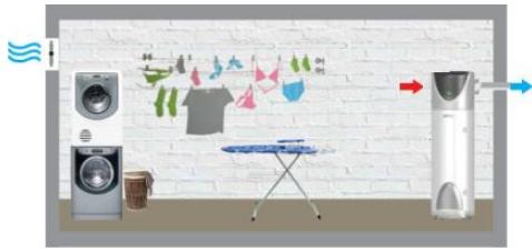
4.1 Location of the appliance
WARNING! Prior to starting any installation activities, ensure that the location where the water heater is to be installed satisfies the following requirements:
a) In the event of water heaters without an air exhaust duct, the room of installation should have a volume of no less than 20m^3 and must be adequately ventilated. Avoid installing the appliance in rooms which may favour frost build-up. Do not install the product in a room containing an appliance that requires air to function (e.g. an open-chamber gas boiler, open-chamber gas water heater, etc.). The product's safety and performance levels are not guaranteed in the event of outdoor installation.
b) The appliance's air exhaust and/or extraction duct (if present) must have access to the outside from the point where the appliance is installed. The connections for the air exhaust and aspiration ducts are located on the upper part of the appliance.
c) Ensure that the installation site and the electrical and hydraulic systems to which the appliance must be connected fully comply with the regulations in force.
d) The chosen site must have, or must be suitable to house, a single-phase 220 - 230V 50Hz power supply socket.
e) The chosen site must be suitable to house a condensate drainage outlet connected to the side of the appliance with a suitable siphon.
f) The chosen site must ensure that the appropriate safety distances from the wall and ceiling can be observed, for the appliance to operate properly and to facilitate maintenance operations.
g) The support surface must ensure a perfectly horizontal operating position (Refer to fig. 2).
h) The chosen site must conform to the appliance's IP protection rating (protection against the penetration of liquids) as specified by the regulations in force.
i) The appliance must not be exposed to direct sunlight, even when windows are present.
j) The appliance must not be exposed to particularly aggressive substances such as acidic vapours, dust or gas-filled environments.
k) The appliance must not be directly installed on telephone lines that are unprotected against overvoltage.
I) The appliance must be installed as close as possible to the points of use to limit heat dispersion along the piping.
m) The air aspirated by the product must be free of dust, acidic vapours and solvents.
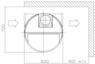
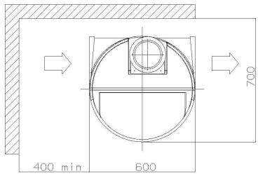
In the event of non-ducted installation, observe the distances from the walls as indicated in Fig. 4.
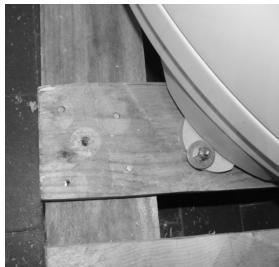
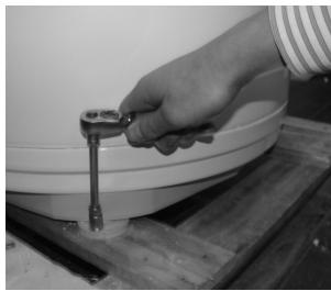
4.2 Positioning on the ground
Refer to Fig. 5
1) Once the suitable installation position has been located, remove the packaging and remove the fixings visible on the pallet where the product is based.
2) Using the appropriate belt, remove the product from the pallet.
3) Fix the feet on the ground (through the appropriate holes) using suitable screws and rawplugs; after positioning the appliance, remove the fabric belt by loosening the relative bolts.
4.3 Air supply connections
Please bear in mind that using air from heated environments may hamper the building's thermal performance.
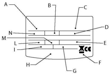
There is one connection for the air intake and two for the air exhaust on the rear side of the appliance. It is important not to remove or tamper with the two grilles and the cover (which bears the wording "Closed air" and is positioned by factory default on the upper part of the product). The outlet air may reach temperatures that are 5 - 10^ lower compared to that of the inlet air and, if not ducted, the temperature of the room of installation may drop sensibly. If the
water heater is intended to function by externally (or through another room) expelling or intaking the air processed by the heat pump, pipes specifically designed for the passage of air may be used. Make sure that the pipes are securely connected and fixed to the product so as to avoid any accidental detachments (for example, use suitable silicone). Only in the event of ducting may the outlet air covers be exchanged, should you wish to use the outlet located on the upper part. Do not in any way manipulate or break the air intake/exhaust grille.
WARNING: Do not use outdoor grills resulting in high losses, such as anti-insect grilles.
The grids used should allow good air flow, the distance between the inlet and outlet air should not be less than 50cm.
Protect pipes from the external wind. The expulsion of air in the chimney is allowed only if the draft is appropriate, is also required periodic maintenance of the barrel, and chimney accessories.
The total static pressure loss due to installation is calculated by adding the loss of the single installed components; this sum must be lower than the static pressure of the fan which is equal to (70 Pa).
See diagram on the last page.

WARNING! A type of canalization not suitable affects product performance and significantly increases the heating time!
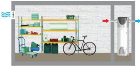
EXAMPLES
| Figure 6 | Inlet air: Not ducted Outlet air: externally ducted |
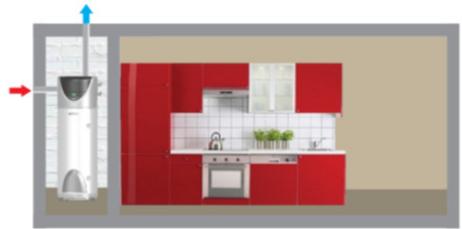
| Figure 7 | Inlet air: internally ducted Outlet air: externally ducted |
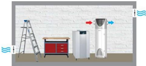
| Figure 8 | Inlet air: externally ducted Outlet air: externally ducted |
| Figure 9 | Installation without ducting |
4.4 Hydraulic connections
Connect the water heater inlet and outlet to pipes or pipe fittings that can withstand the operating pressure and temperature of the hot water, which may reach 75^ . It is not advisable to use materials that cannot withstand such temperatures.
Screw a "T" fitting identified by a blue collar onto the appliance's water inlet pipe.
It is mandatory to fit a safety valve onto the appliance's water inlet pipe. The device must comply with the EN 1487:2000 standard and must have a maximum pressure of 0.7 Mpa (7 bar). Moreover, it must at least include the following components: a cut-off valve, a non-return valve, a control mechanism for the non-return valve, a safety valve and a water pressure shut-off device.
The device's relief outlet must be connected to a relief pipe with a diameter no less than that of the appliance's connection (3/4"), with the aid of a siphon creating an air gap of at least 20mm to allow for visual inspection; this is to prevent any harm to persons and animals or damage to objects should the device activate and for which the manufacturer shall not be held liable. Use a flexible pipe to connect the pressure safety device inlet to the cold water system pipe, using a cut-off valve if necessary. Additionally, a water discharge pipe must be fitted to the outlet in case the drainage tap is opened.
Avoid overtightening the pressure safety device and do not tamper with it. It is normal for water to trickle from the pressure safety device during the heating phase; for this reason, it is necessary to connect the outlet, which must always be left exposed to the atmosphere, to a drainage pipe that slopes downwards and towards an area not subject to frost. It is advisable to also connect the condensate outlet to the same pipe, through the connection located on the lower side of the water heater.
The appliance must not operate with water hardness levels below 12^ ; on the other hand, it is advisable to use a suitably calibrated and monitored water softener in the event of particularly hard water; in this event, the residual hardness must not fall below 15^ .
If the mains pressure is close to the calibrated valve values, a pressure reducer must be installed as far as possible from the appliance.
See Figure 10.
WARNING! It is advisable to carefully wash the system's pipes in order to remove any residues of screw thread, welding or dirt which may hamper the correct operation of the appliance.
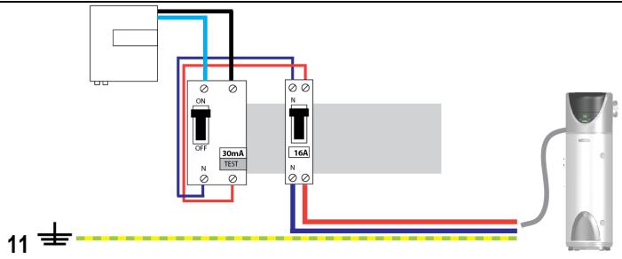
4.5 Electrical connections
| Cable | Protection | ||
| Permanent power supply (cable supplied with the appliance) | 3G 1.5mm² | 16A | |
| EDF signal (cable not supplied with the appliance) | H05V2V2-F | 2G 0.75mm² | 2A |
WARNING: BEFORE YOU GET ACCESS TO TERMINALS, ALL SUPPLY CIRCUITS MUST BE DISCONNECTED. The batteries ensure that the product is protected against corrosion, when the appliance is not powered.
The appliance is supplied with a power supply cable (should the latter need to be replaced, use only original spare parts supplied by the manufacturer).
It is advisable to carry out a check on the electrical system to verify conformity to the regulations in force. Verify that the electrical system can suitably withstand the water heater's maximum power consumption values (refer to the data plate), in terms of the size of the cables and their conformity to the regulations in force. It is forbidden to use multiple outlet sockets, extension cables or adaptors. It is forbidden to use piping from the water, heating and gas systems for earthing the appliance.
Prior to operating the machine, make sure that the electricity mains voltage conforms to the value indicated on the appliance's data plate. The manufacturer of the appliance shall not be held liable for any damage caused by failure to earth the system or due to anomalies in the electric power supply. To disconnect the appliance from the mains, use a bipolar switch complying with all applicable CEI-EN regulations in force (minimum distance between contacts 3mm , switch preferably equipped with fuses).
| PERMANENT ELECTRICAL CONNECTION | |
| Fig. 11 | Use this configuration whenever users do not have a two-tier electricity rate. The water heater will always be connected to the power supply network to ensure 24h operation. |
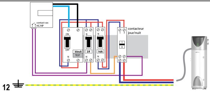
| ELECTRICAL CONNECTION WITH TWO-TIER ELECTRICITY RATE | |
| Fig. 12 | If users have a two-tier electricity rate and a suitable meter, the product may be powered only while the lowest rate applies. During the period in which the appliance is not powered, protection against corrosion through the impressed current anode is ensured by the rechargeable batteries. |
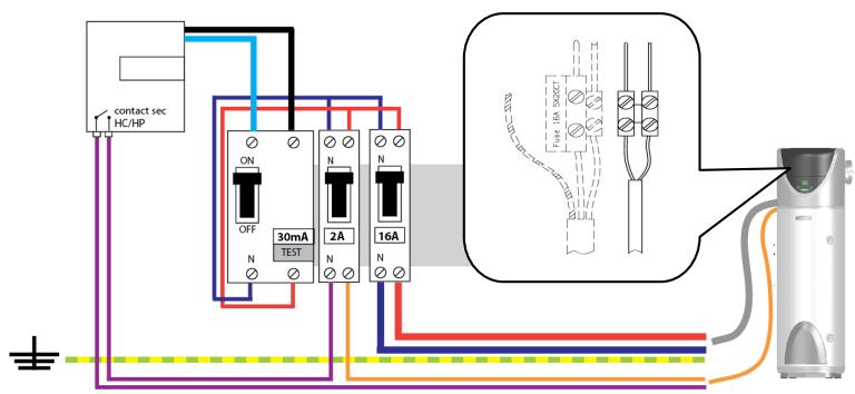
| ELECTRIC CONNECTION WITH TWO-TIER RATE AND HC-HP SIGNAL | |
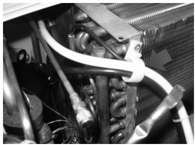
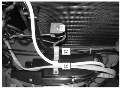
| Fig. 13 | Offers the same cost advantages compared to the two-tier rate configuration but, additionally, it allows for obtaining rapid heating thanks to the BOOST mode that activates heating even with the HP rate. 1) Connect a bipolar cable to the appropriate signal contacts on the meter. 2) Connect the signal bipolar cable to the indicated terminal which is located inside the product, close to the supply terminal. WARNING: the signal cable must be inserted in the hole beneath the power supply cable then anchored with suitable cable clips located inside the product, along the same route of the power supply cable, and tightened in the cable glands near the appropriate terminal; make a suitably-sized hole in the rubber rings for the passage of the cable. 3) Activate the HC-HP function through the installer menu (see Paragraph 7.6). |
4.6 Initial start-up
Once the appliance is connected to the hydraulic and electric systems, the water heater must be filled with water from the domestic water supply network. In order to fill the water heater, it is necessary to open the central tap of the domestic network supply and the nearest hot water tap, while making sure that all the air in the tank is gradually expelled.
Visually inspect for possible water leaks from the flange and pipe fittings and gently tighten them, if necessary.
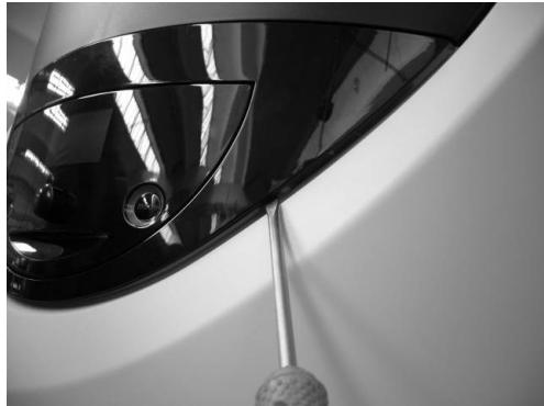
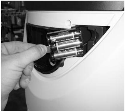
Remove the tab from the batteries, the battery housing is located beneath the frame, to the right of the interface – refer to the picture 16.
5. MAINTENANCE REGULATIONS (for authorised personnel)

WARNING! Observe the general warnings and safety instructions listed in the previous paragraphs and strictly adhere to the indications therein contained.
All maintenance operations and interventions should be performed by qualified personnel (i.e. with the necessary requirements as outlined in the applicable norms in force).
5.1 Draining the appliance
The appliance must be drained if left inactive in a room subject to frost.
When necessary, empty the appliance as follows:
- Disconnect the appliance from the mains.
- Close the shut-off valve, if installed, or the central tap of the domestic water supply network.
- Open the hot water tap (washbasin or bathhtub).
- Open the tap located on the safety valve.
5.2 Routine maintenance
It is advisable to clean the evaporator on an annual basis in order to remove any dust or obstructions. To access the evaporator, it is necessary to remove the fixing screws of the front casing. Verify that the external terminal of the air exhaust duct, and the duct itself, are not obstructed or have not deteriorated. Carry out the same check for the intake duct, if present.
Check the perfect cleaning of grids and ducts.
5.3 Useful information
If the water comes out cold, check the following:
- Whether any error signals appear on the display.
- Whether the terminal board is powered.
The outlet water temperature setting. - When implementing a programming system based on either a time schedule or the "voyage" function, verify whether the programme is in a time slot during which the appliance should function.
- The PCB.
- Whether the tube deflector for the incoming cold water is intact.
The heating elements.
Water comes out boiling hot (steam out of the taps)
Disconnect the appliance from the power supply and have the following checked:
- The PCB.
- The level of limescale build-up in the tank and on the components.
In the event of insufficient hot water supply, verify the following:
The water mains pressure.
The condition of the deflector (jet breaker) on the cold water inlet pipe.
The condition of the hot water inlet pipe.
The electrical components.
Water dripping from the pressure safety device
It is normal for some water to trickle from the tap during the heating phase. To prevent the water from trickling, a suitable expansion vessel must be installed on the flow system. If the dripping continues even after the heating phase, have the following checked:
The device calibration.
The water mains pressure.
Warning: make sure to never obstruct the device's discharge hole!
If the noise level increases during operation in the heat pump mode, inspect the following:
- The moving parts inside the covers.
- The components connected to the product through moving clamps.
OPERATING AND MAINTENANCE INSTRUCTIONS FOR THE USER
6. WARNINGS
6.1 Initial start-up
WARNING! The installation and initial start-up of the appliance must be performed by qualified personnel in compliance with the national regulations in force regarding installation, and in conformity with any regulations issued by local authorities and public health bodies.
If the water heater to be installed not only replaces an existing appliance, but is part of a broader renovation project of the existing hydraulic system or part of a new hydraulic system, the company installing the water heater must issue the customer a declaration of conformity to the laws and regulations in force, once installation is completed. In both cases, the company installing the water heater must carry out the safety and operational checks on the entire system.
Before starting up the water heater, verify whether the installer has completed all the relative installation operations. Make sure to have clearly understood the installer's indications on how to operate the water heater and perform the main operations on the appliance.
The heat pump requires 5 minutes to become fully operational when starting it for the first time.
6.2 Recommendations
In the event of a malfunction and/or faulty operation, turn the appliance off and do not attempt any repairs, but contact qualified personnel. Only original spare parts must be used and any repairs must be carried out exclusively by qualified personnel. Failure to comply with the above-mentioned recommendations may jeopardise the appliance's safety and void the manufacturer's liability. In the event of prolonged inactivity of the water heater, it is advisable to carry out the following:
- Disconnect the appliance from the power supply or, if a switch is mounted upstream from the appliance, turn the switch itself to the "OFF" position.
- Close all taps of the domestic water supply system.
WARNING! It is advisable to drain the appliance whenever it is left inactive in a room subject to frost. This operation must be carried out by qualified personnel only.
WARNING! Hot water at temperatures above 50^ running from taps may immediately cause serious burns. Children, the disabled and the elderly run a greater risk in this regard. Therefore, it is advisable to use a thermostatic mixing valve connected to the appliance's water outlet pipe, which is identified by a red collar. For SOL models the mixing valve becomes mandatory.
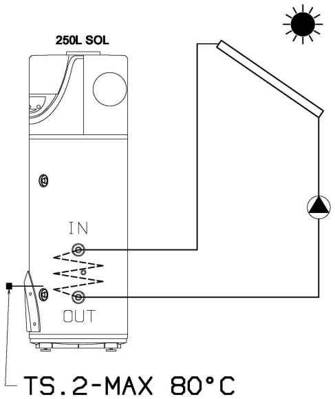
WARNING! (SOL version only) Make sure the temperature detected by the solar control unit probe TS.2 does not exceed 80^ Fig. 15
6.3 Safety regulations
Refer to paragraph 1.1 for the description of the symbols used in the table below.
| Ref. | Warning | Type of risk | Symbol |
| 1 | Do not perform operations that involve removing the appliance from its housing. | Electrocution due to exposure to live components. | ! |
| Flooding caused by water leaking from disconnected piping. | △ | ||
| 2 | Do not leave objects lying on the appliance. | Personal injury caused by the object falling off the appliance as a result of vibrations. | ! |
| Damage to the appliance or any underlying items caused by the object falling off as a result of vibrations. | △ | ||
| 3 | Do not climb onto the appliance. | Personal injury caused by the appliance falling down. | ! |
| Damage to the appliance or any underlying objects caused by the appliance detaching from its fixing brackets and falling. | △ | ||
| 4 | Do not perform any operations that involve opening the appliance. | Electrocution due to exposure to live components. Personal injury caused by burns due to overheated components, or wounds caused by sharp edges or protrusions. | ! |
| 5 | Do not damage the power supply cable. | Electrocution from non-insulated live wires. | ! |
| 6 | Do not climb onto chairs, stools, ladders or unstable supports to clean the appliance. | Personal injury caused by falling from a height or cuts (stepladders shutting accidentally). | ! |
| 7 | Do not attempt to clean the appliance without first switching it off, removing the plug or turning the external switch to the OFF position. | Electrocution due to exposure to live components. | ! |
| 8 | Do not use the appliance for any purpose other than normal household operation. | Damage to the appliance caused by operation overload. Damage to objects caused by improper use. | △ |
| 9 | Do not allow children or inexperienced persons to operate the appliance. | Damage to the appliance caused by improper use. | △ |
| 10 | Do not use insecticides, solvents or aggressive detergents to clean the appliance. | Damage to plastic or painted parts. | △ |
| 11 | Avoid placing any objects and/or appliance beneath the water heater | Damage due to possible water leakage. | △ |
7. INSTRUCTIONS FOR USE
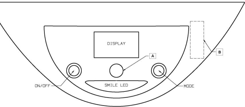
7.1 Control panel description
Refer to Fig. 14.
| A | Knob |
| B | Battery housing (remove frame when replacing batteries) |
The control panel, constructed in a simple and rational way, comprises two buttons and a central knob.
In the upper section, a DISPLAY shows the set temperature or the detected temperature, besides other specific indications such as the operation mode signal, fault codes, settings and information of the product's condition.
The SMILE LED is positioned below the control and signalling zones: it signals the operating status of water heating in the heat pump or heating element.
7.2 Turning the water heater on/off
Turning the appliance on: simply press the ON/OFF button to turn the water heater on.
The DISPLAY visualises the "set" temperature and operation mode, while the HP symbol and/or heating element symbol indicate the operation of the heat pump and/or heating element respectively.
Turning the appliance off: simply press the ON/OFF button to turn the water heater off. The "SMILE LED" turns off, as does the DISPLAY light and other previously active signals; only "OFF" appears on the display. The protection against corrosion is still ensured, while the product will automatically ensure that the temperature of the water in the tank does not fall below 5^ .
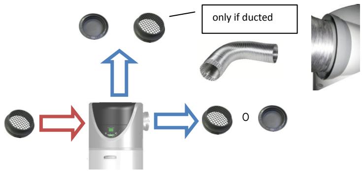
7.3 Setting the temperature
The desired temperature for the hot water can be set by turning the knob clockwise or anti-clockwise (the visualised temperature will flash temporarily).
To visualise the current temperature of the water in the tank, press and release the knob; the relative value will appear for 5 seconds then the set temperature will reappear once again.
The temperatures that can be obtained in the heat pump mode vary between 50^ and 55^ , by factory default setting. By accessing the installer menu (illustrated in Paragraph 7.6), the interval range can be extended to between 40^ and 62^ (bear in mind that temperatures exceeding 55^ in the heat pump mode may lead to greater wear of the compressor).
The maximum temperature that can be obtained with the heating element is 65^ , by factory default setting, and 75^ , by varying the setting on the installer menu.
7.4 Mode of operation
| In normal operating conditions, the "mode" button can be used to vary the operating mode through which the water heater reaches the set temperature. The selected mode will be visualised on the line below the temperature. If the heat pump is active, the following symbol will appear: | HP |
| If the heating element is active, the following symbol will appear: | W |
- AUTO mode: the water heater understands how to reach the desired temperature in a few hours, through the rational use of the heat pump and, only if necessary, of the heating element. The maximum number of hours it takes depends on the P9 - TIME_W parameter (see Paragraph 7.6), which is set to 8 hours by default. (recommended for winter).
- BOOST mode: by activating this mode, the water heater simultaneously uses the heat pump and heating element to reach the desired temperature in the shortest possible time. Once this temperature is reached, the AUTO operating mode is restored.
GREEN mode (to be activated through the installer menu): the water heater will exclude activation of the heating element and will only use the heat pump, thereby ensuring maximum energy saving! The maximum temperature that can be reached depends on the value of the P3 parameter (40^ - 62^) – refer to Paragraph 7.6. - VOYAGE mode (to be activated through the installer menu): studied for situations in which users are absent from the appliance's operating location; this mode allows for programming the number of days of absence, during which the water heater will remain turned off. The appliance will activate only to supply hot water on the day of arrival; protection against corrosion will continue to be guaranteed while the product will automatically ensure that the temperature of the water in the tank does not fall below 5^ . Press the "mode" button until selecting the VOYAGE mode, turn the knob to set the number of days ("days") then press the knob to confirm. The display will only visualise the number of days that remain until the product's reactivation.
7.5 Information menu
| The information menu allows for visualising data for monitoring the product. To enter the menu, press the relative knob and hold for 5 seconds. | ||
| Turn the knob to select the parameters L1, L2, L3 ... L14. The description of the parameter appears on the line below. | ||
| Upon reaching the desired parameter, press the knob to visualise its value. Press the knob or “MODE” button to return to the parameter selection area once again. | ||
| To exit the information menu, press the “mode” button (the appliance will ensure that the menu is automatically exited after the latter has been idle for 10 minutes). | ||
| Parameter | Name | Parameter description |
| L1 | HCHP | Activated/deactivated status of the two-tier rate operation mode. |
| L2 | TIME_W | Maximum accepted hours of powering. |
| L3 | ANTI_B | Activated/deactivated status of the anti-legionnaire's disease function (on/off). |
| L4 | THP | Maximum pre-set temperature of the pump assembly. |
| L5 | TW1 | Temperature recorded by the heating element unit sensor 1. |
| L6 | TW2 | Temperature recorded by the heating element unit sensor 2. |
| L7 | TW3 | Temperature recorded by the hot water pipe sensor. |
| L8 | T AIR | Temperature recorded by the inlet air sensor. |
| L9 | TEVAP | Temperature recorded by the evaporator sensor. |
| L10 | DEFROS | Activated/deactivated status of the defrost function (on/off). |
| L11 | HP h | Meter for internal parameter 1. |
| L12 | HE h | Meter for internal parameter 2. |
| L13 | SW MB | Mainboard software version. |
| L14 | SW HMI | Interface board software version. |
7.6 Installer menu
| CAUTION: THE FOLLOWING PARAMETERS MUST BE ADJUSTED BY QUALIFIED PERSONNEL. | |
| Several of the appliance's settings can be modified through the installer menu. The maintenance symbol is visualised on the left. To enter the menu, keep the knob pressed for 5 seconds then scroll the parameters of the “L - INFO” menu until reaching "PO - CODE". | PO CODE |
| After entering the code (illustrated in the table that follows), turn the knob to select the parameters P1, P2, P3 ... P10. | |
| Upon reaching the parameter to be modified, press the knob to visualise the parameter's value then turn the knob to set the desired value. To return to the parameter selection area, press the knob to store the entered parameter or press "mode" (or wait 10 seconds) to exit without storing the entered value. | 75° T MAX |
| To exit the installer menu, press the “mode” button (the appliance will ensure that the menu is automatically exited after the latter has been idle for 10 minutes). | |
| Parameter | Name | Parameter description |
| P0 | CODE | Code entering to access the installer menu. The number 222 appears on the display: turn the knob until reaching number 234 then press the knob. It will then be possible to access the installer menu. |
| P1 | T Max | Adjustment of the maximum obtainable temperature (from 65°C to 75°C). A higher temperature value allows for using a greater amount of hot water. |
| P2 | T Min | Adjustment of the minimum obtainable temperature (from 50°C to 40°C). A lower temperature setting allows for more energy-efficient operation in the event of limited hot water consumption. |
| P3 | T HP | Adjustment of the maximum temperature obtainable with the heat pump unit (from 50°C to 62°C). Bear in mind that operating at temperatures above 55°C with the heat pump may lead to greater wear of the compressor. |
| P4 | GREEN | Activation/deactivation of the Green function (on/off). See Paragraph 7.4. |
| P5 | ANTI_B | Activation/deactivation of the Anti-Legionnaire's Disease function (on/off). See Paragraph 7.7. |
| P6 | VOYAGE | Activation/deactivation of the Voyage function (on/off). See Paragraph 7.4. |
| P7 | DEFROS | Activation/deactivation of the defrost mode (on/off). If activated, this mode allows the heat pump to function at air temperatures as low as -5°C. |
| P8 | HC-HP | Activation/deactivation of the two-tier rate operation mode. See Paragraph 7.9. |
| P9 | TIME_W | Maximum number of hours of daily heating (from 5h to 24h). |
| P10 | RESET | Resetting of all factory default settings, remember to reset P7 to ON. |
7.7 Anti-legionnaire's disease protection (function activated only through the installer menu)
If activated, the water heater automatically carries out the anti-legionnaire's disease protection function. The water is brought to a temperature of 65^ on a monthly basis and for a maximum time of 15 minutes, so as to avoid germs from developing in the water tank and piping (provided the water has not been brought to T > 57^ at least once for at least 15 minutes). The first heating cycle is performed 3 days after the function has been activated. As these temperatures may cause burns, it is advisable to use a thermostatic mixer.
7.8 Default settings
The appliance is manufactured with a series of default modes, functions or values, as indicated in the table below:
| Parameter | Factory default setting | |
| AUTO MODE | ACTIVATED | |
| BOOST MODE | ACTIVATED | |
| PRE-SET TEMPERATURE | 55°C | |
| P1 | MAX. TEMPERATURE SETTABLE WITH THE HEATING ELEMENT | 65°C |
| P2 | MINIMUM SETTABLE TEMPERATURE | 50°C |
| P3 | MAX. TEMPERATURE SETTABLE WITH THE HEAT PUMP | 55°C |
| P4 | GREEN MODE | DEACTIVATED |
| P5 | ANTI-LEGIONNAIRE'S DISEASE PROTECTION | DEACTIVATED |
| P6 | VOYAGE MODE | DEACTIVATED |
| P7 | DEFROST (active defrost activation) | ACTIVATED |
| P8 | HC-HP (two-tier rate operation mode) | DEACTIVATED |
| P9 | TIME_W (no. of accepted hours of powering) | 8h |
7.9 Operation with two-tier electricity rate
To be able to operate also on appliances with a two-tier rate system, the control logic calculates the number of average hours a day during which the power supply is available in the economy mode (HC).
A self-learning function ensures that the appliance reaches the pre-set temperature in the time range during which the economy rate applies; the maximum limit of hours is determined by the P9 TIME_W parameter; after the initial start-up (or after switching off the hardware), the default setting is 8 hours.
7.10 Anti-frost function
In any event, if the temperature of the water in the tank falls below 5^ while the appliance is powered, the heating element (1,000 W) will be automatically activated to heat the water up to 16^ . If the GREEN mode is set, the appliance will perform this operation through the heat pump.
7.11 Faults
As soon as a fault occurs, the appliance enters into the fault mode while the display emits flashing signals and visualises the error code. The water heater will continue supplying hot water provided the fault affects only one of two the heating units, by activating the heat pump or heating element.
If the fault involves the heat pump, the symbol "HP" will flash on the screen, while the heating element symbol will flash if the fault involves this component. If both components are affected, both symbols will flash.
| Error code | Cause | Heating element operation | Heat pump operation | What to do |
| E1 | Heating occurs without any water in the water tank | OFF | OFF | Verify the causes of the lack of water (leakage, faulty hydraulic connections, etc.) |
| E2 | Excessive temperature of the water in the tank | OFF | ON | Turn the appliance off then on again; if the problem persists, contact the technical assistance service |
| E3 | Fault during heating with the heating element | OFF | ON | Verify that the heating element functions properly |
| E4 | Sensor fault – heating element zone | OFF | ON | Check or replace the heating element zone sensors, if necessary |
| E5 | Excessive difference between the temperatures of the heating element zone sensors | OFF | ON | Check or replace the sensors, if necessary |
| H1 | Excessive pressure in the refrigeration circuit, or faulty reading on the pressure switch | ON | OFF | Try restarting the machine; if the error persists, contact the technical assistance service |
| H2 | Fan fault | ON | OFF | Check that the fan is not broken and that the evaporator is not obstructed. Check whether the hot gas valve functions properly and replace it if necessary. Check the perfect cleaning of grids and ducts |
| H3 | Compressor fault | ON | OFF | Verify whether the compressor functions properly and/or check for any refrigerant gas leakages |
| H4 | Evaporator obstructed | ON | OFF | Check the perfect cleaning of grids and ducts |
| H6 | Air sensor fault | ON | OFF | Verify whether the sensor is properly connected and positioned, and replace it if necessary |
| H7 | Evaporator sensor fault | ON | OFF | Verify whether the sensor is properly connected and positioned, and replace it if necessary |
| H8 | Hot water pipe sensor fault | ON | OFF | Verify whether the sensor is properly connected and positioned, and replace it if necessary |
| H9 | Active defrost fault | ON | OFF | Check that the fan is not broken and that the evaporator is not obstructed. Check whether the hot gas valve functions properly and replace it if necessary. Check the perfect cleaning of grids and ducts |
| F1 | PCB fault | OFF | OFF | Try turning the appliance off then on again and verify the operation of the control boards, if necessary |
| F2 | Excessive number of ON/OFF (RESET) | ON | ON | Temporarily disconnect the product and the batteries |
| F3 | Lack of communication between the PCB and interface | ON | ON | Try turning the appliance off then on again and verify the operation of the control boards or replace them, if necessary |
| F4 | Empty tank (EMPTY), impressed current anode circuit open | ON | ON | Verify whether there is any water in the tank, check or replace the impressed current anode, if necessary |
| F5 | Short-circuit on the impressed current anode circuit | ON | ON | Check or replace the impressed current anode if necessary |
8. MAINTENANCE
8.1 Routine maintenance performed by users
It is advisable to rinse out the appliance after each routine or extraordinary maintenance intervention.
The pressure safety device must be operated regularly to verify that it is not clogged and to remove any limescale deposits.
Check that the condensate drainage pipe is not obstructed.
Check the perfect cleaning of grids and ducts.
The batteries must be replaced every 2 years or in case of losses. Make sure that they are correctly disposed of and exclusively replace them with 3 AA-type rechargeable batteries (minimum 2,100 mAh); observe the polarities as illustrated in the battery housing. The battery housing is located beneath the frame, to the right of the interface – refer to the picture 16.
The appliance should be unplugged when you remove the batteries.
8.2 Water heater disposal
The appliance contains R134a-type refrigerant gas which must not be released into the atmosphere. In case of permanent decommissioning of the water heater, ensure that disposal procedures are carried out by qualified personnel only.
This product conforms to EU Directive 2002/96/EC.

The barred dustbin symbol appearing on the appliance's data plate indicates that the product must be disposed of separately from household waste once it reaches the end of its lifespan, and transferred to a waste disposal site for electric
and electronic equipment, or returned to the dealer when purchasing a new appliance of the same kind. The user is responsible for delivering the decommissioned appliance to a suitable waste disposal site. Proper separated collection of the decommissioned appliance and its successive eco-compatible recycling, treatment and disposal contributes to preventing negative effects on the environment and health and favours the reuse of the materials comprising the product. For further details on the available waste collection systems, contact your local waste disposal office, or the dealer from which the product was purchased.
This appliance includes rechargeable batteries: these must be removed before disposing of the appliance and placed in specific disposal containers. The batteries are located in the area below the interface frame.
1
2
3
4
5
6
7
8
9
10
13
14
15
16
(*) Recommandé grille, gerwijd raster, dedicated grid, griglia dedicata, recommenciones red, recomendado grid.