
Alchemist - Cooktop Klarstein - Free user manual and instructions
Find the device manual for free Alchemist Klarstein in PDF.


User questions about Alchemist Klarstein
0 question about this device. Answer the ones you know or ask your own.
Ask a new question about this device
Download the instructions for your Cooktop in PDF format for free! Find your manual Alchemist - Klarstein and take your electronic device back in hand. On this page are published all the documents necessary for the use of your device. Alchemist by Klarstein.
USER MANUAL Alchemist Klarstein
INHALT
Berlin Brands Group UK Limited
PO Box 42
272 Kensington High Street
London, W8 6ND
United Kingdom
Dear Customer,
Congratulations on purchasing this device. Please read the following instructions carefully and follow them to prevent possible damages. We assume no liability for damage caused by disregard of the instructions and improper use. Scan the QR code to get access to the latest user manual and more product information.

CONTENTS
Safety Instructions 32
Appliance Description 34
Getting Started and Operation 39
Cleaning and Care 41
Troubleshooting 42
Installation Instructions for Built-In 43
Gas Specifications 49
Disposal Considerations 55
Manufacturer & Importer (UK) 55
SAFETY INSTRUCTIONS
Please take the time to read this instruction manual before installing or using the appliance. This instruction booklet must be kept with the appliance for any future reference. If the appliance is sold or transferred to another person, ensure the booklet is passed on to the new user.
- This appliance shall be installed in accordance with regulations in force and only used in a well ventilated space.
- Prior to installation, ensure that the gas and electrical supply complies with the type stated on the rating plate.
- Where this appliance is installed in marine craft or in caravans, it should not be used as a space heater.
- The gas pipe and electrical cable must be installed in such a way that they do not touch any parts or the appliance.
• This appliance should be installed by a qualified technician or installer. - The adjustment conditions for this appliance are stated on the label or data plate.
- Remove all packaging before using the appliance.
- After unpacking the appliance, make sure the product is not damaged and that the connection cord is in perfect condition. Otherwise, contact the dealer before installing the appliance.
- The adjacent furniture and all materials used in the installation must be able to withstand a minimum temperature of 85 °C above the ambient temperature of the
• room it is located in, whilst in use. - In the event of burner flames being accidentally extinguished, turn off the burner control and do not attempt to re-ignite the burner for at least one minute.
- The use of a gas cooking appliance results in the production of heat and moisture in the room in which it is installed. Ensure that the kitchen is well ventilated: keep natural ventilation holes open or install a mechanical ventilation device (mechanical extractor hood).
- Prolonged intensive use of the appliance may call for additional ventilation, for example opening of a window, or more effective ventilation, for example increasing he level of mechanical ventilation where present.
- Do not allow children to play near or with the appliance.
• The appliance gets hot when it is in use.
• Children should be kept away until it has cooled.
• This appliance is designed to be operated by adults.
• Children can also injure themselves by pulling pans or pots off the appliance. - This appliance is not intended for use by children or other persons whose physical, sensory or mental capabilities or lack of experience and knowledge prevents them from using the appliance safety without supervision or instruction by a responsible person to ensure that they can use the appliance safety.
• Only use the appliance for preparing food. - Do not modify this appliance. Burner panel is not designed to operate from an external timer or separate remote control system.
- The use of a gas cooking appliance results in the production of heat and moisture in the room in which it is installed. Ensure that the kitchen is well ventilated.
Keep natural ventilation holes open or install a mechanical ventilation device (mechanical extractor hood).
- Do not use this appliance if it comes in contact with water. Do not operate this appliance with wet hands.
- The heating and cooking surfaces of the appliance become hot when they are in use, take all due precautions.
- Do not use large cloths, tea towels or similar as the ends could touch the flames and catch fire.
• Never leave the appliance unattended when cooking. - Unstable or misshapen pans should not be used on the appliance as they can cause an accident by tipping or spillage.
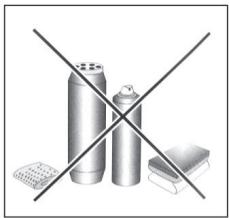
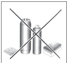
- Do not use or store flammable materials in the storage drawer near this appliance.
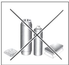
- Perishable food, plastic items and aerosols may be affected by heat and should not stored above or below the appliance.
- Do not spray aerosols in the vicinity of this appliance while it is in operaiton.
- Ensure the control knobs are in the '●' position when not in use.
- This appliance is intended for domestic cooking only. It is not designed for commercial or industrial purposes.
- Prolonged intensive use of the appliance may call for additional ventilation, for example opening of a window, or increasing the level of mechanical ventilation where present.
• Use heat-resistant pot holders or gloves when handling hot pots and pans. - Do not let pot holders come near open flames when lifting cookware.
- Take care not to let pot holders or gloves get damp or wet, as this causes heat to transfer through the material quicker with the risk of burning yourself.
- Only ever use the burners after placing pots and pans on them. Do not heat up any empty pots or pans.
- Never use plastic or aluminium foil dishes on the appliance.
- When using other electrical appliances, ensure the cable does not come into contact with the appliance surfaces of the cooking appliance.
- If you have any mechanical parts eg. an artificial heart in your body, consult a doctor before using the appliance.
- Do not use a tea towel or similar materials in place of a pot holder. Such cloths can catch fire on a hot burner.
- When using glass cookware, make sure it is designed for top plate cooking. If the surface is made of glass-cracked, switch off the appliance to avoid defeat electrocution.
- To minimise the possibility of burns, ignition of flammable materials and spillage, turn cookware handles toward the side or center of the top plate without extending over adjacent burners.
• Always turn burner controls off before removing cookware. - Carefully watch foods being fried at a high flame setting.
• Always heat fat slowly and watch as it heats. - Foods for frying should be as dry as possible. Frost on frozen foods or moisture on fresh foods can cause hot fat to bubble up and over the sides of the pan.
- Never try to move a pan of hot fat, especially a deep fat fryer. Wait until the fat is completely cool.
10036335
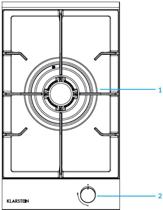
1 Triple ring wok burner
2 Control knob
10034968

1 Rapid burner
2 Semi-rapid burner
3 Control knob for rapid burner (top)
4 Control knob for semi-rapid burner (bottom)
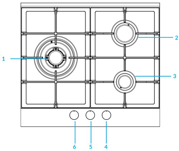
1 Triple ring wok burner
2 Semi-rapid burner
3 Semi-rapid burner
4 Control knob for auxiliary burner (bottom right)
5 Control knob for semi-rapid burner (top right)
6 Control knob for triple ring wok burner (left)
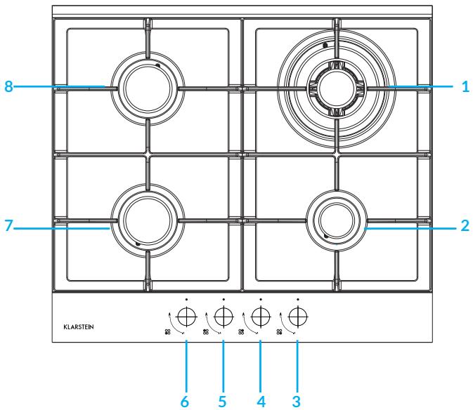
1 Triple ring wok burner
2 Auxiliary burner
3 Control knob for auxiliary burner (bottom right)
4 Control knob for triple ring wok burner (top right)
5 Control knob for semi-rapid burner (top left)
6 Control knob for semi-rapid burner (bottom left)
7 Semi-rapid burner
8 Semi-rapid burner
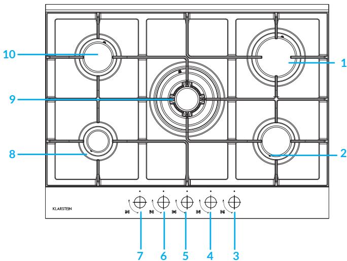
1 Rapid burner
2 Semi-rapid burner
3 Control knob for semi-rapid burner (bottom right)
4 Control knob for rapid burner (top right)
5 Control knob for wok burner(in the middle)
6 Control knob for semi-rapid burner (top left)
7 Control knob for auxiliary burner (bottom left)
8 Auxiliary burner
9 Triple ring wok burner
10 Semi-rapid burner
GETTING STARTED AND OPERATION
The position of the corresponding gas burner is indicated on each control knob.
Gas burners
The burners are different in size and power. Choose the most appropriate one for the diameter of the cookware being used.
The burner can be regulated with the corresponding control knob by using one of the following settings:
| OFF | |
| High | |
| Low |
On those models fitted with a safety device
The knob must be pressed for about 6 seconds until the flame is lighted and warmed up.
On those models fitted with an igniter
The electric ignition button, identified by the symbol, must be pressed first, then the corresponding knob is pushed and turned in the counter-clockwise direction to the "High" setting.
To light a burner: Simply press the corresponding knob and turn it in the counterclockwise direction to the High setting, keep press until the burner is lighted.

CAUTION
Fire and explosion hazard! If the flame goes out accidentally, turn off the gas with the control knob and try to light it again at least 1 minute later.
To turn off a burner: Turn the knob in the clockwise direction until it is stopped (it should be on the "." setting).
Practical Advice
For best performance, follow these general guidelines:
- Use the appropriate cookware for each burner (see table) in order to prevent the flame to reach the side of the pot or pan;
• Always use cookware with a flat bottom and keep the lid on; - When the contents come to a boil, turn the knob to "Low".
| Burner | ∅ Cookware diameter (cm) |
| Auxiliary burner | 10-14 cm |
| Semi-rapid burner | 16-20 cm |
| Rapid burner | 22-24 cm |
| Triple ring wok burner | 24-26 cm |
To identify the type of burner, refer to the designs in the section entitled, "Burner and Nozzle Specifications".
Flame selection
As the burners are adjusted correctly, the flame should be light blue, and the inner flame should be clear. The size of flame depends on the position of the related control knob.

Burner ON, large flame
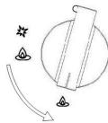
Burner ON, small flame
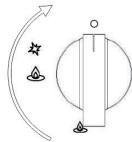
Burner OFF
The burner must be set at a large flame during the initial phase of cooking, which makes food boil quickly. Then should turn knob to the saving flame position to maintain the cooking. It is possible to adjust the flame size stepless.
It is prohibited to adjust the flame between the Burner OFF and Burner ON large flame positions.
High quantity of energy can be conserved if the hob is used correctly, parameters are designed correctly, and appropriate cookware is used. The energy conservation be as follows:
- Up to 60 % are conserved when proper pots are used,
- Up to 60 % are conserved when the unit is operated correctly and the suitable flame size is chosen.
It is a prerequisite for efficient and energy-saving operation of hob that the burners are kept clean at all times (in particular the flame slots and nozzles).
CLEANING AND CARE
Before cleaning or performing maintenance on your gas hob, disconnect it from the electrical power supply (included battery power).
To extend the lifespan of the gas hob, it is absolutely indispensable that it is cleaned carefully, thoroughly and usually, please keep in mind to the following:
- The enamelled parts and the glass top, must be washed with warm water without using abrasive powders or corrosive substances which could ruin them;
- The removable parts of the burners should be washed usually with warm water and soap, make sure to remove caked-on substances;
- Automatic igniter pin, the end must be cleaned carefully and usually, make sure ignition keep working normally.
- Stainless steel top plate and other steel parts can be stained if keep touch with high concentration calcareous water or corrosive detergents (containing phosphorus). To extend the lifespan, we advise these parts be rinsed thoroughly with water and dry them by blowing. It is a good idea to clean up any spills too.
- After glass hob working, the surface must be cleaned by a damp cloth to remove dust or food residues. Glass surface should be cleaned regularly with warm water and non-corrosive detergent.
While the cooking surface is warm, clean it with a suitable cleaning product and paper towels, then rub with a damp cloth and dry surface. Such as aluminium foil, plastic items, objects made of synthetic material, sugar or foods with a high sugar content that have been melted onto the surface, it must be removed immediately.
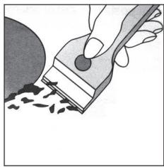
While the cooking surface is still hot, clean it with a scraper and a transparent protective film which prevent to make more dirt. This also protect the surface from damage caused by food with a high sugar content.
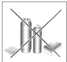
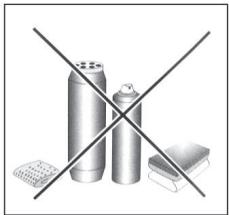
Do not use abrasive sponges or cleaning products, these holds true for chemically aggressive cleaners, like oven sprays and stain removers.
Cleaning the grill/pan support, it is recommended to clean it while it is still hot. To move grill away from the hob and put it in sink, remove the food residues or grease first, after grill has cooled, rinse it with water.
Greasing the gas valves
Over time, the gas valves may be stocked, and it is difficult to turn on/off. For this case, should clean the inside of valve and greased it.
Kind reminder: This procedure must be performed by a technician authorized by the manufacturer.
TROUBLESHOOTING
| Problem | Check to make sure that: |
| The burner cannot be lighted or the flame is not uniform around the burner. | The gas holes on the burner are not clogged;All of the movable parts of burners are fixed correctly;There is no air flow around the cooking surface |
| The flame does not keep lighting to the burner with thermocouple | You press the knob all the way;You keep pressing the knob for enough time to activate the thermocouple.The gas holes are not clogged in the area corresponding to the thermocouple. |
| The flame goes out while turning knob to "Low" setting. | The gas holes are not clogged.There is no air flow around the cooking surface.The minimum has been adjusted correctly (see the section entitled "Minimum Regulation"). |
| The cookware is not stable. | The bottom of the cookware is perfectly flat.The cookware is centred correctly on the burner.The support grids have not been inverted. |
INSTALLATION INSTRUCTIONS FOR BUILT-IN
The following instructions are directed at the qualified installer, so the installation and maintenance procedures may be followed in the most professional and expert manner.
Important: Unplug the electrical connection before performing any maintenance or regular upkeep work.
Positioning for gas hob
Important: this unit may be installed and used only in permanently ventilated rooms.
The following requirements must be observed:
- The room must be fitted with a ventilation system which ventilates smoke and gases from combustion to the outside of rooms. This must be done by hood or electric ventilator.
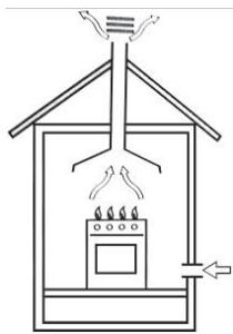
In a chimney stack or branched flue (exclusively for cooking appliances).
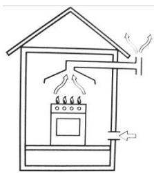
Directly to the outside.
- The room must be allowed for the influx of the air which is for proper combustion. The air flow for combustion purposes must not less than 2 m3/h per kW of installed capacity. The air supply will be effected by influx from the outside through a duct, its inner cross section is at least 100 cm2 and must not be blocked accidentally.
The gas hob without safety devices, to prevent flame go out accidentally, must have a ventilation working on twice volume. For example, a minimum of 200 cm2 (Fig. 3). Otherwise, the room can be vented indirectly through adjacent rooms which is fitted with ventilation ducts to the outside. Although the adjacent rooms are not shared areas, bedrooms, but fire risk is hidden(see illustration).
Adjacent room
Room to be vented
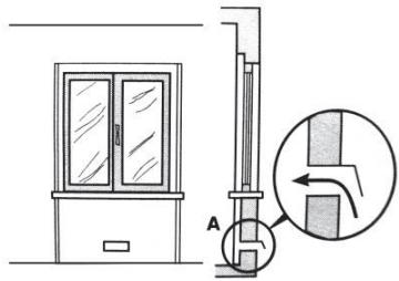
Examples of ventilation holes for comburent air.

Enlarging the ventilation slot between window and floor
- Intensive and prolonged working of the gas hob that needs to intensify ventilation, e.g. opening windows or increasing the power of the air intake system (if present)..
- Liquefied petroleum gases are heavier than air, so settle it downward. Rooms in which LPG tanks are installed must be fitted with ventilation to the outside to avoid of gas leakage.
Therefore, LPG tanks which are empty or partially full, must not be installed or stored in rooms or spaces below ground level (cellars etc.). It is a good idea to keep only the tank which is working currently in the room, and make sure that it is not closed to heating source (ovens, fireplaces, stoves, etc.).
Installation of built-in gas hob
The gas hobs are designed with protection degree against excessive heating, the appliance can be installed next to cabinets, and the height should not exceed the hob. For a correct installation, the following precautions must be followed:
- The hob may be located in a kitchen, a diner or bed/ sitting room, but not in a bathroom or shower room.
- The furniture standing near to the unit, it is higher than the working boards, it must be placed at least 110 mm distance to the edge of the board.
- The cabinets should be positioned near to the hood at a height of 420 mm at least (see illustration).
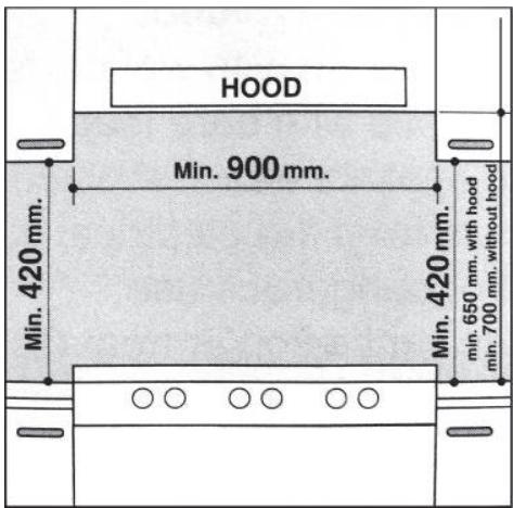
- Hob should be installed directly under a cupboard, the latter should be at least 700 mm from the worktop, as shown in Fig. C.
- Fixing fittings (hooks, screws) are provided to place the hob on work top, measure 20 to 40 mm in thickness (see Fig. 6).
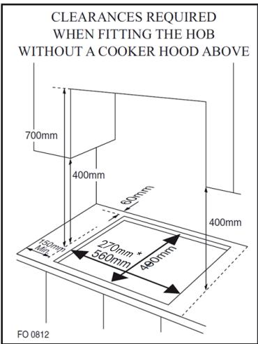
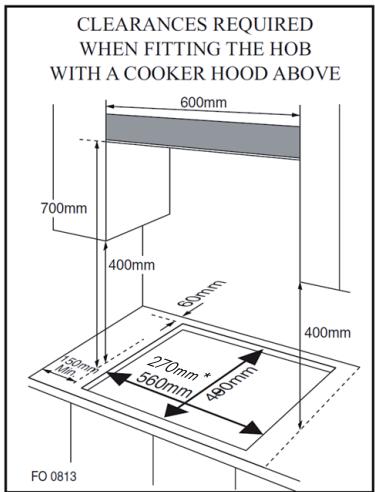
* Built-in size for 1 and 2-zone model
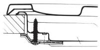
Hook position for H=20 mm top
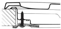
Hook position for H=30 mm top
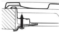
Hook position for H=40 mm top
NOTE: Use the hooks contained in the "accessories bag".
- In the event the gas hob is not installed on a built-in oven, a wooden panel must be inserted for insulation. This panel must be placed at least 20 mm distance from the bottom of hob.
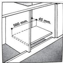
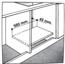
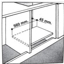
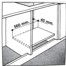
Important: When installing the hob on a built-in oven, the oven should be placed on two wooden strips; in the case of a joining cabinet surface, remember to leave a space of 45 × 560 mm at least from the back side.
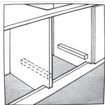
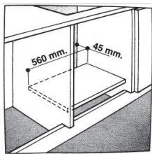
When installing hob on a built-in oven without forced ventilation, ensure that have air inlets and outlets to ventilate the interior of the cabinet adequately.
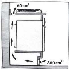
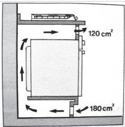
Gas connection for gas hob
The gas hob should be connected to the gas-supply by a registered installer. During installation it is essential to fit an approved gas tap to isolate the supply from the hob for the convenience of any subsequent removal or servicing. Connect the hob to the gas mains or liquid gas, it must be carried out according to the prescribed regulation in force, and only after it is ascertained that it is adaptable to the type of gas to be used. If not, follow the instructions indicated in the paragraph headed "Adaptation to different gas types". In the case of connection to liquid gas by tank, use pressure regulators that conform to the regulation in force.
Important: For safety, for the correct regulation of gas use and long life of the hob, ensure that the gas pressure conforms to the indications given in table 1 "Burners and Nozzle Specifications".
Connection to non-flexible tube
- Connection to the gas source must be done in such a way as to not create any stress points at any part of the gas hob.
- The hob is fitted with an adjustable "L" shape connector and a gasket to the gas supply.
- The connector should be dismounted and the gasket must be replaced.
- The feeding connector of the gas to the hob is threaded 1/2 gas cylinder.
Connection to flexible steel tube
The gas feed connector to the hob is threaded, 1/2" connector for round gas pipe.
Only use pipes and sealing gaskets that conform to the standards currently in force. The maximum length of the flexible pipes must not exceed 2000 mm. Once the connection has been made, ensure that the flexible metal tube does not touch any moving parts and not be crushed.
Check the Seal
Once the hob was installed, make sure all the connections are properly sealed, use a soapy water to test, never use flame.
Electrical Connection
The hob fitted with a tripolar electrical supply cord which are designed to be used alternating current. According to the indications on the rating plate located under the hob. The earthing wire can be identified by its yellow-green colour.
In the case of installation over a built-in electric oven, the electrical connections for the hob and oven should be independent, not only for safe purpose, but also be convenient to remove them in the future.
Electrical Connection for Gas hob
Fit the supply cord with a standard plug for the demand rate indicated on the rating plate or connect it directly to the electrical mains. In the latter case, a single pole switch must be placed between the hob and the mains, with a minimum opening between the
contacts of 3 mm in compliance with current safety codes (the earthing wire must not be interrupted by the switch). The power supply cord must be positioned so that it does not reach a temperature in excess of 50 °C than room temperature at any point.
Before actual connection make sure that.
Before actual connection make sure that:
- The fuse and electrical system can withstand the load required by the hob;
- The electrical supply system is equipped with an efficient earth hook-up according to the norms and regulations prescribed by law;
• The plug or switch are easily accessible.
Important: the wires in the main lead are coloured in accordance with the following code:
• Green & Yellow - Earth
- Blue-Neutral
- Browc -Live
As the colours of the wires in the main lead may not correspond with the coloured markings identifying the terminals in your plug, proceed as follows:
- As the colours of the wires in the main lead may not correspond with the coloured markings identifying the terminals in your plug, proceed as follows: Connect the Green & Yellow wire to terminal marked "E" or 1/2 or coloured Green or Green & Yellow.
- Connect the Brown wire to the terminal marked "L" or coloured Red.
- Connect the Blue wire to the terminal marked "N" or coloured Black.
GAS SPECIFICATIONS
TABLE 1: Burners and Nozzle Specifications
| G20 | G30 | |||
| Burner | Thermal power (kW) | Nozzle 1/100 (mm) | Thermal power (kW) | Nozzle 1/100 (mm) |
| Auxiliary (Small) (A) | 1.0 | 71 | 1.0 | 45 |
| Semi rapid (Medium) | 1.8 | 97 | 1.8 | 59 |
| Rapid (R) | 2.4 | 110 | 2.4 | 67 |
| Triple Ring (TR) | 3.4 | 125 | 3.4 | 82 |
| Supply pressures | 20 mbar | 50 mbar | ||
At 15°C and 1013 mbar - dry gas
| P.C.I.G20 | 37.78 MJ/m3 | P.C.I.G25.1 | 32.51 MJ/m3 |
| P.C.I.G25 | 32.49 MJ/m3 | P.C.I.G27 | 30.98 MJ/m3 |
| P.C.I.G2.350 | 27.20 MJ/ m3 | P.C.I.G30 | 49.47 MJ/Kg |
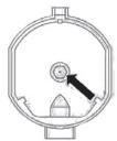
Replacement of burner nozzle: loosen the nozzle with a dedicated wrench(7). Fit the new nozzle according to the required gas type (see table 1 for reference).
After you have converted the gas hob to another gas type, make sure you have placed a label containing that information on the appliance:
TABLE 2: How to convert gas Source
| Burners | Flame | Converting the hob from LPG to natural gas | Converting the hob from natural gasGas to LPG |
| Regular burners | Full flame | Replace the burner nozzle according to the guidelines in Table 1. | Replace the burner Nozzle according to the guidelines in Table 1 |
| Saving flame | Loosen the adjustment.Spindle (see fig.7 below)And adjust the flame. | Loosen the adjustment.Spindle (see fig.7 below)And adjust the flame. |
Valve adjustment
Valve adjustment should be done with the control knob set at Burner ON saving flame position.
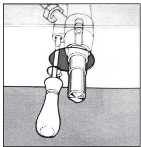
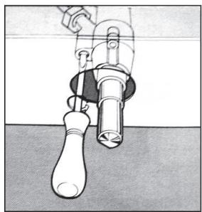
Remove the knob, and adjust the flame with a tiny screwdriver (see fig.7 below)
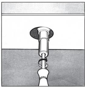
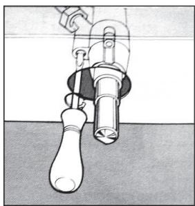
To check the adjusted flame: heat the burner at full open position for 10 minutes. Then turn the knob into the saving setting. The flame should not extinguish nor move to the nozzle. If it extinguish or moves to the nozzle, readjust the valves.
TABLE 3: Adapting to different types of gas
| Burner | Type of Gas | Pressure | Nozzle dia. | Nominal Charge | Reduced Charge | ||||
| ∅ | g/h | l/h | kW | kcal/h | kW | kcal/h | |||
| Auxiliary | Natural G20 | 20 | 71 | - | 95 | 1.0 | 860 | 0.40 | 344 |
| Butane G30 | 30 | 52 | 72.6 | - | 1.0 | 860 | 0.40 | 344 | |
| 37 | 47 | 72.6 | - | 1.0 | 860 | 0.40 | 344 | ||
| 50 | 45 | 72.6 | - | 1.0 | 860 | 0.40 | 344 | ||
| Semi-rapid | Natural G20 | 20 | 97 | - | 171 | 1.8 | 1548 | 0.60 | 516 |
| Butane G30 | 30 | 67 | 130.8 | - | 1.8 | 1548 | 0.60 | 516 | |
| 37 | 64 | 130.8 | - | 1.8 | 1548 | 0.60 | 516 | ||
| 50 | 59 | 130.8 | - | 1.8 | 1548 | 0.60 | 516 | ||
| Rapid | Natural G20 | 20 | 110 | - | 228 | 2.4 | 2064 | 0.90 | 774 |
| Butane G30 | 30 | 77 | 174 | - | 2.4 | 2064 | 0.90 | 774 | |
| 37 | 73 | 174 | - | 2.4 | 2064 | 0.90 | 774 | ||
| 50 | 67 | 174 | - | 2.4 | 2064 | 0.90 | 774 | ||
| Triple-ring wok | Natural G20 | 20 | 125 | - | 323 | 3.4 | 2924 | 1.50 | 1290 |
| Butane G30 | 30 | 93 | 247 | - | 3.4 | 2924 | 1.50 | 1290 | |
| 37 | 88 | 247 | - | 3.4 | 2924 | 1.50 | 1290 | ||
| 50 | 82 | 247 | - | 3.4 | 2924 | 1.50 | 1290 | ||
TABLE 4: : Gas source and national comparison table
| Gas group | Country | Supply pressure |
| I3+(28-30/37) | BE, CH, CY, CZ, ES, FR, GB, GR, IE, IT, LT, LU, LV, PT, SK, SI. | G30 Butane at 28-30mbar and G31 Propane at 37 mbar |
| I3B/P(30) | BG, CY, DK, EE, FI, FR, GB, HU, HR, IT, IS, LT, LU, MT, NL, NO, RO,SE, SI, SK, TR. | G30 Butane and G31 Propane at 30 mbar |
| I3B/P(37) | PL | G30 Butane and G31 Propane at 37 mbar |
| I3B/P(5O) | AT, CH, DE, SK | G30 Butane and G31 Propane at 50 mbar |
| I3P(37) | BE, CH, CY, CZ, IT, ES, FR, GR, GB, HR, LT, NL, PT, SK, IE, SI. | G31 Propane at 37 mbar |
| I2H | AT, BG, CH, CY, CZ, DK, EE, ES, FR, FI, GR, GB, HR, HU, IS, IE, IT, LU, LV, LT, NO, PT, RO, SK, SI, SE, TR. | G20 at 20 mbar |
| I2E | DE, LU, PL | G20 at 20/25 mbar |
| I2E+ | BE, FR | G20/G25 at 20/25 mbar |
| I2EK | NL | G25.3 at 25 mbar |
| I2ELS | PL | G20 at 20 mbar and G2.350 at 13 mbar |
| I2ELW | PL | G20/G27 at 20 mbar |
| I2HS | HU | G20/G25.1 at 25 mbar |
| II2H3+ | CH, CZ, ES, GB, GR, IE, IT, LT, PT, SK | G20 at 20 mbar, G30 butane at 28-30 mbar and G31 propane at 37 mbar |
| II2E3B/P | RO | G20 at 20 mbar, G30 butane and G31 propane at 30 mbar |
| II2E3B/P | DE | G20 at 20 mbar, G30 butane and G31 propane at 50 mbar |
| II2HS3B/P | HU | G20/G25.1 at 25 mbar, G30 butane and G31 propane at 30 mbar |
| II2ELWLS3B/P | PL | G20/G27 at 20 mbar, G2.350 at 13 mbar, G30 butane and G31 propane at 37 mbar |
| II2ELL3B/P | DE | G20/G25 at 20 mbar, G30 butane and G31 propane at 50 mbar |
| Model identification | 10036335 | |||
| Type of hob | Gas Hob | |||
| Number of gas burner | -- | -- | 1 | -- |
| Symbol | Burner | Value | Unit | |
| Energy efficiency per gas burner | EEgas\ burner | Wok burner | 57.05 | % |
| Rapid burner | -- | % | ||
| Semi-rapid burner | -- | % | ||
| Auxiliary burner | N/A | % | ||
| Energy efficiency per gas hob | EEgas\ hob | 57.05 | % | |
| Model identification | 10034968 | |||
| Type of hob | Gas Hob | |||
| Number of gas burner | -- | -- | 2 | -- |
| Symbol | Burner | Value | Unit | |
| Energy efficiency per gas burner | EE gas burner | Wok burner | -- | % |
| Rapid burner | 54.74 | % | ||
| Semi-rapid burner | 57.61 | % | ||
| Auxiliary burner | N/A | % | ||
| Energy efficiency per gas hob | EE gas hob | 56.18 | % | |
| Model identification | 10034969 | |||
| Type of hob | Gas Hob | |||
| Number of gas burner | -- | -- | 4 | -- |
| Symbol | Burner | Value | Unit | |
| Energy efficiency per gas burner | EE gas burner | Wok burner | 57.05 | % |
| Rapid burner | 54.74 | % | ||
| Semi-rapid burner | 57.61 | % | ||
| Auxiliary burner | N/A | % | ||
| Energy efficiency per gas hob | EE gas hob | 57.42 | % | |
| Model identification | 10034970 | |||
| Type of hob | Gas Hob | |||
| Number of gas burner | -- | -- | 5 | -- |
| Symbol | Burner | Value | Unit | |
| Energy efficiency per gas burner | EE gas burner | Wok burner | 57.05 | % |
| Rapid burner | 54.74 | % | ||
| Semi-rapid burner | 57.61 | % | ||
| Auxiliary burner | N/A | % | ||
| Energy efficiency per gas hob | EE gas hob | 56.75 | % | |
| Model identification | 10037804 | |||
| Type of hob | Gas Hob | |||
| Number of gas burner | -- | -- | 3 | -- |
| Symbol | Burner | Value | Unit | |
| Energy efficiency per gas burner | EE gas burner | Wok burner | 57.05 | % |
| Rapid burner | N/A | % | ||
| Semi-rapid burner | 57.61 | % | ||
| Auxiliary burner | N/A | % | ||
| Energy efficiency per gas hob | EE gas hob | 57.33 | % | |
DISPOSAL CONSIDERATIONS

If there is a legal regulation for the disposal of electrical and electronic devices in your country, this symbol on the product or on the packaging indicates that this product must not be disposed of with household waste. Instead, it must be taken to a collection point for the recycling of electrical and electronic equipment. By disposing of it in accordance with the rules, you are protecting the environment and the health of your fellow human beings from negative consequences. For information about the recycling and disposal of this product, please contact your local authority or your household waste disposal service.
This product contains batteries. If there is a legal regulation for the disposal of batteries in your country, the batteries must not be disposed of with household waste. Find out about local regulations for disposing of batteries. By disposing of them in accordance with the rules, you are protecting the environment and the health of your fellow human beings from negative consequences.
MANUFACTURER & IMPORTER (UK)
Manufacturer:
Chal-Tec GmbH, Wallstrasse 16, 10179 Berlin, Germany.
Importer for Great Britain:
Berlin Brands Group UK Limited
PO Box 42
272 Kensington High Street
London, W8 6ND
United Kingdom
Chère cliente, cher client,
SOMMAIRE
Brûleur éteint

Berlin Brands Group UK Limited
PO Box 42
272 Kensington High Street
London, W8 6ND
United Kingdom
Estimado cliente,
ÍNDICE
Quemador apagado
En el exterior.

Berlin Brands Group UK Limited
PO Box 42
272 Kensington High Street
London, W8 6ND
United Kingdom
Gentile cliente,
INDICE
PRODUTTORE E IMPORTATORE (UK)
Produttore:
Chal-Tec GmbH, Wallstraße 16, 10179 Berlino, Germania.
Berlin Brands Group UK Limited
PO Box 42
272 Kensington High Street
London, W8 6ND
United Kingdom

KLARSTEIN





- INHALT
- DEAR CUSTOMER
- CONTENTS
- SAFETY INSTRUCTIONS
- GETTING STARTED AND OPERATION
- GAS BURNERS
- ON THOSE MODELS FITTED WITH A SAFETY DEVICE
- ON THOSE MODELS FITTED WITH AN IGNITER
- CAUTION
- PRACTICAL ADVICE
- FLAME SELECTION
- CLEANING AND CARE
- GREASING THE GAS VALVES
- INSTALLATION INSTRUCTIONS FOR BUILT-IN
- POSITIONING FOR GAS HOB
- INSTALLATION OF BUILT-IN GAS HOB
- GAS CONNECTION FOR GAS HOB
- CONNECTION TO NON-FLEXIBLE TUBE
- CONNECTION TO FLEXIBLE STEEL TUBE
- CHECK THE SEAL
- ELECTRICAL CONNECTION
- ELECTRICAL CONNECTION FOR GAS HOB
- BEFORE ACTUAL CONNECTION MAKE SURE THAT
- GAS SPECIFICATIONS
- VALVE ADJUSTMENT
- DISPOSAL CONSIDERATIONS
- MANUFACTURER & IMPORTER (UK)
- MANUFACTURER
- IMPORTER FOR GREAT BRITAIN
- CHÈRE CLIENTE, CHER CLIENT
- SOMMAIRE
- ESTIMADO CLIENTE
- ÍNDICE
- GENTILE CLIENTE
- INDICE
- PRODUTTORE E IMPORTATORE (UK)
- PRODUTTORE
- KLARSTEIN
Brand : Klarstein
Model : Alchemist
Category : Cooktop