
Q32V5E - Monitor AOC - Free user manual and instructions
Find the device manual for free Q32V5E AOC in PDF.
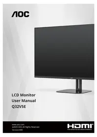


| Product Type | LED-backlit LCD Monitor |
| Brand | AOC |
| Model | Q32V5E |
| Screen Size | 31.5 inches |
| Panel Type | VA |
| Backlight | LED |
| Resolution | 2560 x 1440 (QHD) |
| Refresh Rate | 75 Hz |
| Response Time | 4 ms (GtG) |
| Brightness | 300 cd/m² |
| Contrast Ratio | 3000:1 (typical) |
| Viewing Angles | 178° / 178° |
| Display Colors | 16.7 million |
| Inputs | 2 x HDMI, 1 x DisplayPort |
| Audio Output | 1 x 3.5 mm headphone jack |
| Built-in Speakers | 2 x 3 W |
| Tilt Range | -5° to 20° |
| VESA Mounting | 100 x 100 mm |
| Power Consumption | 35 W (typical), 0.5 W standby |
| Weight (with Stand) | 7.5 kg |
| Dimensions (with Stand, WxHxD) | 714 x 520 x 230 mm |
| Package Contents | Monitor, stand, power cable, HDMI cable, quick start guide |
| Special Features | Flicker-Free, Low Blue Light Mode, Adaptive-Sync (FreeSync) |
| Cleaning and Maintenance | Wipe with a soft dry cloth; avoid harsh chemicals; disconnect power before cleaning. |
| Safety Information | Use a stable surface; ensure proper ventilation; avoid exposure to moisture; do not remove the back cover. |
| Spare Parts and Repairability | Contact AOC support for authorized service; use only certified replacement parts. |
Frequently Asked Questions - Q32V5E AOC
User questions about Q32V5E AOC
0 question about this device. Answer the ones you know or ask your own.
Ask a new question about this device
Download the instructions for your Monitor in PDF format for free! Find your manual Q32V5E - AOC and take your electronic device back in hand. On this page are published all the documents necessary for the use of your device. Q32V5E by AOC.
USER MANUAL Q32V5E AOC
LCD Monitor User Manual Q32V5E
Safety....1
National Conventions....1
Power....2
Installation 3
Cleaning....4
Other....5
Setup 6
Contents in Box....6
Set-up Stand & Base 7
Adjusting Viewing Angle 8
Connecting the Monitor 9
Wall Mounting 10
Adaptive-Sync function....11
Adjusting 12
Hotkeys....12
OSD Setting....13
Game Setting 14
Preset Mode....16
HDR 17
Picture....18
Input....20
Settings 21
Audio....22
OSD Setup 23
Information 24
LED Indicator 25
Troubleshoot 26
Specification 27
General Specification....27
AOC Monitors Panel Pixel Defect Policy 28
Preset Display Modes 30
Pin Assignments.... 31
Plug and Play 32
Safety
National Conventions
The following subsections describe notional conventions used in this document.
Notes, Cautions, and Warnings
Throughout this guide, blocks of text may be accompanied by an icon and printed in bold type or in italic type. These blocks are notes, cautions, and warnings, and they are used as follows:

NOTE: A NOTE indicates important information that helps you make better use of your computer system.

CAUTION: A CAUTION indicates either potential damage to hardware or loss of data and tells you how to avoid the problem.

WARNING: A WARNING indicates the potential for bodily harm and tells you how to avoid the problem. Some warnings may appear in alternate formats and may be unaccompanied by an icon. In such cases, the specific presentation of the warning is mandated by regulatory authority.
Power
The monitor should be operated only from the type of power source indicated on the label. If you are not sure of the type of power supplied to your home, consult your dealer or local power company.
The monitor is equipped with a three-pronged grounded plug, a plug with a third (grounding) pin. This plug will fit only into a grounded power outlet as a safety feature. If your outlet does not accommodate the three-wire plug, have an electrician install the correct outlet, or use an adapter to ground the appliance safely. Do not defeat the safety purpose of the grounded plug.
Unplug the unit during a lightning storm or when it will not be used for long periods of time. This will protect the monitor from damage due to power surges.
Do not overload power strips and extension cords. Overloading can result in fire or electric shock.
To ensure satisfactory operation, use the monitor only with UL listed computers which have appropriate configured receptacles marked between 100-240V AC, Min. 5A.
The wall socket shall be installed near the equipment and shall be easily accessible.
Installation
Do not place the monitor on an unstable cart, stand, tripod, bracket, or table. If the monitor falls, it can injure a person and cause serious damage to this product. Use only a cart, stand, tripod, bracket, or table recommended by the manufacturer or sold with this product. Follow the manufacturer's instructions when installing the product and use mounting accessories recommended by the manufacturer. A product and cart combination should be moved with care.
Never push any object into the slot on the monitor cabinet. It could damage circuit parts causing a fire or electric shock. Never spill liquids on the monitor.
Do not place the front of the product on the floor.
If you mount the monitor on a wall or shelf, use a mounting kit approved by the manufacturer and follow the kit instructions.
Leave some space around the monitor as shown below. Otherwise, air-circulation may be inadequate hence overheating may cause a fire or damage to the monitor.
To avoid potential damage, for example the panel peeling from the bezel, ensure that the monitor does not tilt downward by more than -5 degrees. If the -5 degree downward tilt angle maximum is exceeded, the monitor damage will not be covered under warranty.
See below the recommended ventilation areas around the monitor when the monitor is installed on the wall or on the stand:
Installed with stand

Cleaning
Clean the cabinet regularly with a water-dampened, soft cloth.
When cleaning use a soft cotton or microfiber cloth. The cloth should be damp and almost dry, do not allow liquid into the case.


Please disconnect the power cord before cleaning the product.
Other
If the product is emitting a strange smell, sound or smoke, disconnect the power plug IMMEDIATELY and contact a Service Center.
Make sure that the ventilating openings are not blocked by a table or curtain.
Do not engage the LCD monitor in severe vibration or high impact conditions during operation.
Do not knock or drop the monitor during operation or transportation.
The power cords shall be safety approved. For Germany, it shall be H03VV-F, 3G, 0.75 mm², or better. For other countries, the suitable types shall be used accordingly.
Excessive sound pressure from earphones and headphones can cause hearing loss. Adjustment of the equalizer to maximum increases the earphones and headphones output voltage and therefore the sound pressure level.
Setup
Contents in Box

Monitor
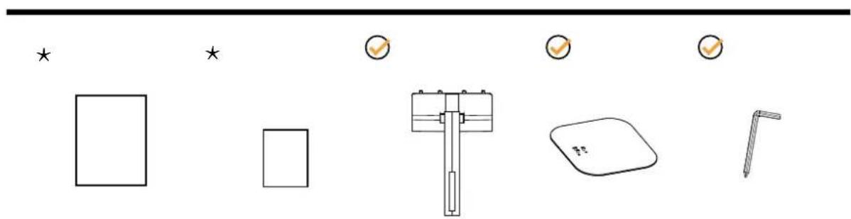
Quick Start Guide Warranty Card Stand Base Screwdriver

* Not all signal cables will be provided for all countries and regions. Please check with the local dealer or AOC branch office for confirmation.
Set-up Stand & Base
Please setup or remove the base following the steps as below.
Setup:

Remove:


NOTE: Display design may differ from those illustrated.
Adjusting Viewing Angle
To achieve the best viewing experience, it is recommended that the user can make sure they are able to look at their whole face on the screen, then adjust the monitor's angle based on personal preference.
Hold the stand so you will not topple the monitor when you change the monitor's angle.
You are able to adjust the monitor as below:


NOTE:
Do not touch the LCD screen when you change the angle. Touching the LCD screen may cause damage.
Warning:
- To avoid potential screen damage, such as panel peeling, ensure that the monitor does not tilt downward by more than -5 degrees.
- Do not press the screen while adjusting the angle of the monitor. Grasp only the bezel.
Connecting the Monitor
Cable Connections In Back of Monitor and Computer:

- Power
- HDMI1
- HDMI2
- DisplayPort
- Earphone
Connect to PC
- Connect the power cord to the back of the display firmly.
- Turn off your computer and unplug its power cable.
- Connect the display signal cable to the video connector on the back of your computer.
- Plug the power cord of your computer and your display into a nearby outlet.
- Turn on your computer and display.
If your monitor displays an image, installation is complete. If it does not display an image, please refer Troubleshooting.
To protect equipment, always turn off the PC and LCD monitor before connecting.
Wall Mounting
Preparing to Install An Optional Wall Mounting Arm.
![graph LR A["Raw Material"] --> B["Packaging"] B --> C["Product"] C --> D["Final Product"]](/content/2026/08/1633056/images/ddd843288a56923e42101460a234a3822687a19598cff53ab23e7b38f3330ddd.jpg)
This monitor can be attached to a wall mounting arm you purchase separately. Disconnect power before this procedure. Follow these steps:
- Remove the base.
- Follow the manufacturer's instructions to assemble the wall mounting arm.
- Place the wall mounting arm onto the back of the monitor. Line up the holes of the arm with the holes in the back of the monitor.
- Reconnect the cables. Refer to the user's manual that came with the optional wall mounting arm for instructions on attaching it to the wall.

Specification of wall hanger screws: M4*(10+X)mm, (X=Thickness of Wall mount bracket)
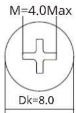

NOTE: Noted: VESA mounting screw holes are not available for all models, please check with the dealer or official department of AOC. Always contact manufacturer for wall-mount installation.

* Display design may differ from those illustrated.
Warning:
- To avoid potential screen damage, such as panel peeling, ensure that the monitor does not tilt downward by more than -5 degrees.
- Do not press the screen while adjusting the angle of the monitor. Grasp only the bezel.
- Adaptive-Sync function works with HDMI/DisplayPort
- Compatible Graphics Card: Recommend list is as below, also could be checked by visiting www.AMD.com
- AMD Radeon™ RX 480
• AMD Radeon™ RX 470 - AMD Radeon™ RX 460
Graphics Cards
- Radeon™ RX Vega series
- Radeon™ RX 500 series
- Radeon™ RX 400 series
- Radeon™ R9/R7 300 series (R9 370/X, R7 370/X, R7 265 except)
• Radeon™ Pro Duo (2016) - Radeon™ R9 Nano series
- Radeon™ R9 Fury series
- Radeon™ R9/R7 200 series (R9 270/X, R9 280/X except)
Processors
- AMD Ryzen™ 7 2700U
- AMD Ryzen™ 5 2500U
• AMD Ryzen™ 5 2400G
• AMD Ryzen™ 3 2300U
• AMD Ryzen™ 3 2200G - AMD PRO A12-9800
- AMD PRO A12-9800E
- AMD PRO A10-9700
• AMD PRO A10-9700E - AMD PRO A8-9600
- AMD PRO A6-9500
- AMD PRO A6-9500E
- AMD PRO A12-8870
- AMD PRO A12-8870E
• AMD PRO A10-8770
• AMD PRO A10-8770E
• AMD PRO A10-8750B
• AMD PRO A8-8650B - AMD PRO A6-8570
- AMD PRO A6-8570E
- AMD PRO A4-8350B
- AMD A10-7890K
- AMD A10-7870K
- AMD A10-7850K
- AMD A10-7800
- AMD A10-7700K
- AMD A8-7670K
- AMD A8-7650K
- AMD A8-7600
- AMD A6-7400K
Adjusting
Hotkeys
![graph TD A["①"] --> B["②"] C["③"] --> D["④"] E["⑤"] --> F["③"] G["①"] --> H["②"] I["③"] --> J["④"] K["⑤"] --> L["③"] M["①"] --> N["②"] O["③"] --> P["④"] Q["⑤"] --> R["③"] S["①"] --> T["②"] U["③"] --> V["④"] W["⑤"] --> X["③"] Y["①"] --> Z["②"] AA["③"] --> AB["④"] AC["⑤"] --> AD["③"] AE["①"] --> AF["②…](/content/2026/08/1633056/images/9a0537d2ff988e5bae505834d6ef6a123768a7495a657dd4ed7bf90aa2b89020.jpg)
| 1 Source/Up |
| 2 Volume/Down |
| 3 Preset Mode/Left |
| 4 Brightness/Right |
| 5 Power/Menu/Enter |
Power/Menu/Enter
Press the Power button to turn on the monitor.
When there is no OSD, Press to display the OSD or confirm the selection. Press about 2 second to turn off the monitor.
Source/Up
When the OSD is closed, press up key to activate the signal source function, then press the down or up key to select the signal source.
Preset Mode/Left
When there is no OSD, press left key to open Preset Mode function, then press down or up key to select Preset Mode.
Brightness/Right
When there is no OSD, Press right key to active brightness adjustment bar, Press Left or Right to adjust brightness.
Volume/Down
When there is no OSD, Press down button to active volume adjustment bar, Press Left or Right to adjust volume.
OSD Setting
Basic and simple instruction on the control keys.
![graph TD A["BRIGHTNESS 70"] --> B["CONTRAST 50"] B --> C["PRESET MODE Standard"] C --> D["RESOLUTION 2560X1440"] D --> E["INPUT SOURCE HDMI2"] F["OSD Setup"] --> G["Settings"] G --> H["Audio"] H --> I["Game Setting"] I --> J["Shadow Control"] I --> K["Low Input Lag"] I --> L["Game Color"] I --> M["A…](/content/2026/08/1633056/images/7bcb59d57d04b8d6d7b24545213b10edc122f1cee2828d53390576e96d74169b.jpg)
1). Press the MENU-button to activate the OSD window.
2). Press Left or Right to navigate through the functions. Once the desired function is highlighted, press the MENU-button to activate it, press Left or Right to navigate through the sub-menu functions. Once the desired function is highlighted, press MENU-button to activate it.
3). Press Left or Right to change the settings of the selected function. Press Exit-button to exit. If you want to adjust any other function, repeat steps 2-3.
4). OSD Lock/Unlock Function: To lock or unlock the OSD, press and hold the Down-button for 10s while OSD function is not active.
Notes:
1). If the product has only one signal input, the item of "Input Select" is unable to be adjusted.
2). If the input signal resolution is the native resolution or Adaptive-Sync, then the item "Image Ratio" is invalid.
Game Setting
![graph TD A["BRIGHTNESS 70"] --> B["CONTRAST 50"] B --> C["PRESSET MODE Standard"] C --> D["RESOLUTION 2560X1440"] D --> E["INPUT SOURCE HDMI2"] F["OSD Setup"] --> G["Settings"] G --> H["Audio"] H --> I["Game Setting"] I --> J["Shadow Control"] I --> K["Low Input Lag"] I --> L["Game Color"] I --> M["…](/content/2026/08/1633056/images/4f646d415eba94f4f30bb27dcc74f0a0d4309e6050de27a13dde0a80d2fce009.jpg)
| Shadow Control 0 | ~20 | Shadow Control Default is 0, then end-user can adjust from 0 to 20 increase for a clearer picture. If picture is too dark to be saw the detail clearly, adjusting from 0 to 20 for a clear picture. |
| Low Input Lag Off | / On Turn off frame buffer to decrease input lag. | |
| Game Color 0 ~ 20 | Game Color will provide 0-20 level for adjusting saturation to get a better picture. | |
| Adaptive-Sync Off | / On | Disable or Enable Adaptive-Sync.Adaptive-Sync Run Reminder: When the Adaptive-Sync feature is enabled, there may be flashing in some game environments. |
| Dial Point Off / On | / Dynamic | The"Dial Point" function places an aiming indicator in the center of screen for helping gamers to play First Person Shooter (FPS) games with accurate and precise aiming. |
| Dark Boost | Off / Level 1 /Level 2 / Level 3 | Enhance the screen details in the dark or bright area to adjust the brightness in the bright area and ensure that it is not oversaturated. |
| MBR 0 ~ 20 | MBR (Motion Blur Reduction) Provides 0-20 levels of adjustments to reduce motion blur.Note: The MBR function can be adjusted when Adaptive-Sync is turned off, and the refresh rate ≥75Hz. | |
| MBR Sync Off / On | Disable or Enable MBR Sync (Motion Blur Remove).Note: The MBR Sync function can be adjusted when Adaptive-Sync is turned On, and the input signal is variable frequency, and the field frequency is ≥75Hz. | |
| Overdrive | Off | Adjust the response time.Note:1. If the user adjusts OverDrive to "Strong" the displayed image may be blurred. Users can adjust the OverDrive level or turn it off according to their preferences.2. The "Boost" function is optional when Adaptive-Sync is turned off, and the refresh rate is ≥75Hz.3. The screen brightness will decrease when the "Boost" function is turned on. |
| Weak | ||
| Medium | ||
| Strong | ||
| Boost | ||
Note:
1). When "HDR Mode" under "Preset Mode" is enable, the items "Shadow Control", "Game Color", "Dark Boost" cannot be adjusted.
2). When "HDR" under "Preset Mode" is set to "DisplayHDR", the items "Shadow Control", "Game Color", "Dark Boost", "MBR", "MBR Sync" and "Boost" under "Overdrive" cannot be adjusted.
When "HDR" under "Preset Mode" is set to "HDR Picture", "HDR Movie" or "HDR Game", the items "Game Color", "Dark Boost", "MBR", "MBR Sync" and "Boost" under "Overdrive" cannot be adjusted.
3). When the "Color Space" under "Picture" is set to "sRGB", the items "Shadow Control", "Game Color", "Dark Boost", "MBR", "MBR Sync" and "Boost" under "Overdrive" cannot be adjusted.
Preset Mode
![graph TD A["BRIGHTNESS 70"] --> B["CONTRAST 50"] B --> C["PRESET MODE Standard"] C --> D["RESOLUTION 2560X1440"] D --> E["INPUT SOURCE HDMI2"] F["Game Setting"] --> G["Preset Mode"] H["Picture"] --> I["Standard"] J["Input"] --> K["Internet"] L["Settings"] --> M["Movie"] N["Audio"] --> O["Photographe…](/content/2026/08/1633056/images/734d3f83328a9de50d8e3e0006d95be970d2205b00e03d7ab78ea105229f0759.jpg)
| Standard Enhance readability for suitable web and mobile games. | |
| Internet Internet Mode. | |
| Movie Movie Mode. | |
| Photographer Photographer Mode. | |
| Eco Mode Eco Mode | |
| Reading Reading Mode. | |
| HDR Effect - Picture | Set the HDR Effect according to your usage requirements.HDR Effect - Movie |
| HDR Effect - Game | |
| Sports Sports Mode. | |
| FPS For playing FPS (First Person Shooters) games. Improves black level in dark theme. | |
| RTS For playing RTS (Real Time Strategy) games. Improves the image quality. | |
| Racing For playing Racing games, Provides fastest response time and high color saturation. | |
| Reset Color Reset the Color to default. | |
HDR
![graph TD A["BRIGHTNESS 70"] --> B["CONTRAST 50"] B --> C["PRESET MODE HDR Game"] C --> D["RESOLUTION 2560X1440"] D --> E["INPUT SOURCE HDMI2"] F["Game Setting"] --> G["HDR"] G --> H["Off"] G --> I["DisplayHDR"] G --> J["HDR Picture"] G --> K["HDR Movie"] G --> L["HDR Game"] M["Picture"] --> N["Setti…](/content/2026/08/1633056/images/6ba7271dfa9d44779be0c43389e38ff723a18981a8496dcf248d113fbafff592.jpg)
| HDR | Off | Set the HDR profile according to your usage requirements.Note:When HDR is detected, the HDR option is displayed for adjustment. |
| DisplayHDR | ||
| HDR Picture | ||
| HDR Movie | ||
| HDR Game |
Picture
![graph TD A["BRIGHTNESS 70"] --> B["CONTRAST 50"] B --> C["PRESET MODE Standard"] C --> D["RESOLUTION 2560X1440"] D --> E["INPUT SOURCE HDMI2"] F["Game Setting"] --> G["Picture"] H["Preset Mode"] --> G I["Input"] --> G J["Settings"] --> G K["Audio"] --> G L["OSD Setup"] --> G G --> M["Brightness"] G…](/content/2026/08/1633056/images/5a78da794c860007ce4b67d04caa1748881f4631b44ce0bd7ea71eb60a9a43ab.jpg)
| Brightness 0-100 Backlight Adjustment. | |
| Contrast 0-100 Contrast from Digital-register. | |
| Color Space | Panel Native Standard color space panel. |
| sRGB sRGB Color space. | |
| Sharpness 0-100 Sharpness Adjustment. | |
| Gamma 1.8/2.0/2.2/2.4/2.6 Adjust Gamma. | |
| Color Temp. | Native Recall Native Color Temperature from EEPROM. |
| 5000K Recall 5000K Color Temperature from EEPROM. | |
| 6500K Recall 6500K Color Temperature from EEPROM. | |
| 7500K Recall 7500K Color Temperature from EEPROM. | |
| 8200K Recall 8200K Color Temperature from EEPROM. | |
| 9300K Recall 9300K Color Temperature from EEPROM. | |
| 11500K Recall 11500K Color Temperature from EEPROM. | |
| User Define Restore Color Temperature from EEPROM. | |
| Red 0-100 Red gain from Digital-register. |
| Green 0-100 Green gain from Digital-register. | ||
| Blue 0-100 Blue gain from Digital-register. | ||
| DCR | Off Disable dynamic contrast ratio. | |
| On Enable dynamic contrast ratio. | ||
| Clear Vision | Off/Weak/Medium/Strong | Full-screen apply sharpening function. |
| LowBlue Mode | Off | Decrease blue light wave by controlling color temperature. |
| Multimedia | ||
| Internet | ||
| Office | ||
| Reading | ||
| Image Ratio Full/Aspect/1:1 Select image ratio for display. | ||
Note:
1). When "HDR Mode" under "Preset Mode" is enable, the items "Contrast", "Gamma", "Color Temp.", "Color Space" and "LowBlue Mode" cannot be adjusted.
2). When "HDR" under "Preset Mode" is set to "DisplayHDR", all the items under "Picture" except "HDR", "Sharpness" cannot be adjusted. When "HDR" under "Preset Mode" is set to "HDR Picture", "HDR Movie" or "HDR Game", the items "Gamma", "Color Temp.", "DCR", "Color Space" and "LowBlue Mode" cannot be adjusted.
3). When the "Color Space" under "Picture" is set to "sRGB", the items "Contrast", "Gamma" and "Color Temp." cannot be adjusted.
Input
![graph TD A["Input"] --> B["Game Setting"] A --> C["Preset Mode"] A --> D["Picture"] A --> E["Settings"] A --> F["Audio"] A --> G["OSD Setup"] H["Auto"] --> I["HDMI1"] H --> J["HDMI2"] H --> K["DisplayPort"] L["BRIGHTNESS 70"] --> M["CONTRAST 50"] N["CONTRAST"] --> O["PRESET MODE Standard"] P["PRESET…](/content/2026/08/1633056/images/99af640503cc7ff79ea90e285a761371c4c0d8eb0f5fef5225a1190ba5403e30.jpg)
| Auto Select input signal source Automatically. |
| HDMI1 Select HDMI1 input signal source. |
| HDMI2 Select HDMI2 input signal source. |
| DisplayPort Select DisplayPort input signal source. |
Settings
![graph TD A["BRIGHTNESS 70"] --> B["Game Setting"] C["CONTRAST 50"] --> D["Preset Mode"] D --> E["Picture"] E --> F["Input"] G["PRRESET MODE Standard"] --> H["Settings"] H --> I["Audio"] H --> J["OSD Setup"] K["RESOLUTION 2560X1440"] --> L["Language"] K --> M["Break Reminder"] K --> N["Off Timer(hr)"…](/content/2026/08/1633056/images/a1c5e8e363a98e88829e53ceb5590ce40bdf0e734d752b286661d4041d5196ab.jpg)
| Language Select the OSD language. | ||
| Break Reminder Off / On | Break reminder if the user continuously works for more than 1hrs. | |
| Off Timer(hr) 0-24 Select | DC off time. | |
| DDC/CI No / Yes Turn On | /Off DDC/CI Support. | |
| Resolution Notice Off / On Optimal resolution prompt. | ||
| Reset | No / Yes Reset the menu to default. | |
| ENERGY STAR® | ENERGY STAR® available for selective models. | |
Audio
![graph TD A["BRIGHTNESS 70"] --> B["CONTRAST 50"] B --> C["PRESET MODE Standard"] C --> D["RESOLUTION 2560X1440"] D --> E["INPUT SOURCE HDMI2"] F["Game Setting"] --> G["Audio"] H["Preset Mode"] --> G I["Picture"] --> G J["Input"] --> G K["Settings"] --> G L["OSD Setup"] --> G G --> M["Volume"] G -->…](/content/2026/08/1633056/images/8bdbc22083a3eb2d876ffb5e6c6f02f2829bfbc8d633e4fb81a1a5bc1d70698e.jpg)
| Volume 0-100 Volume Adjustment. | |
| Mute Off / On Mute the volume. |
OSD Setup

| Transparence 0-100 Adjust the transparence of OSD. | ||
| H. Position 0-100 Adjust the horizontal position of OSD. | ||
| V. Position 0-100 Adjust the vertical position of OSD. | ||
| OSD Time Out 5-120 Adjust the OSD Timeout. |
Information

LED Indicator
| Status LED Color | |
| Full Power Mode White | |
| Active-off Mode Orange |
Troubleshoot
| Problem & Question Possible Solutions | |
| Power LED Is Not ON | Make sure the power button is ON and the Power Cord is properly connected to a grounded power outlet and to the monitor. |
| No image on the screen | •Is the power cord connected properly?Check the power cord connection and power supply.•Is the video cable connected correctly?(Connected using the HDMI cable)Check the HDMI cable connection.(Connected using the DisplayPort cable)Check the DisplayPort cable connection.* HDMI/DisplayPort input is not available on every model.•If the power is on, reboot the computer to see the initial screen (the login screen.)If the initial screen (the login screen) appears, boot the computer in the applicable mode (the safe mode for Windows 7/8/10) and then change the frequency of the video card.(Refer to the Setting the Optimal Resolution)If the initial screen (the login screen) does not appear, contact the Service Center or your dealer.•Can you see “Input Not Supported” on the screen?You can see this message when the signal from the video card exceeds the maximum resolution and frequency that the monitor can handle properly.Adjust the maximum resolution and frequency that the monitor can handle properly.•Make sure the AOC Monitor Drivers are installed. |
| Picture Is Fuzzy & Has Ghosting Shadowing Problem | Adjust the Contrast and Brightness Controls.Press hot-key (AUTO) to auto-adjust.Make sure you are not using an extension cable or switch box. We recommend plugging the monitor directly to the video card output connector on the back. |
| Picture Bounces, Flickers Or Wave Pattern Appears In The Picture | Move electrical devices that may cause electrical interference as far away from the monitor as possible.Use the maximum refresh rate your monitor is capable of at the resolution you are using. |
| Monitor Is Stuck In Active Off-Mode" | The Computer Power Switch should be in the ON position.The Computer Video Card should be snugly fitted in its slot.Make sure the monitor's video cable is properly connected to the computer.Inspect the monitor's video cable and make sure no pin is bent.Make sure your computer is operational by hitting the CAPS LOCK key on the keyboard while observing the CAPS LOCK LED. The LED should either turn ON or OFF after hitting the CAPS LOCK key. |
| Missing one of the primary colors (RED, GREEN, or BLUE) | Inspect the monitor's video cable and make sure that no pin is damaged.Make sure the monitor's video cable is properly connected to the computer. |
| Screen image is not centered or sized properly | Adjust H-Position and V-Position or press hot-key (AUTO). |
| Picture has color defects (white does not look white) | Adjust RGB color or select desired color temperature. |
| Horizontal or vertical disturbances on the screen | Use Windows 7/8/10/11 shut-down mode to adjust CLOCK and FOCUS.Press hot-key (AUTO) to auto-adjust. |
| Regulation & Service | Please refer to Regulation & Service Information at www.aoc.com (to find the model you purchase in your country and to find Regulation & Service Information in Support page.) |
Specification
General Specification
| Panel | Model Name Q32V5E | ||
| Driving System TFT Color LCD | |||
| Viewable Image Size 80.1 cm diagonal | |||
| Pixel Pitch 0.2727mm(H) x 0.2727mm(V) | |||
| Display Color 1.07B (8bits+FRC) | [1] | ||
| Others | Horizontal Scan Range 30k-150kHz | ||
| Horizontal Scan Size(Maximum) 698.112mm | |||
| Vertical Scan Range 48-100Hz | |||
| Vertical Scan Size(Maximum) 392.688mm | |||
| Optimal Preset Resolution 2560x1440@60Hz | |||
| Max Resolution 2560x1440@100Hz | |||
| Plug & Play VESA DDC2B/CI | |||
| Power Source 100-240V~ 50/60Hz 1.5A | |||
| Power Consumption | Typical(default brightness and contrast) | 25W | |
| Max. (brightness = 100, contrast =100) | ≤48W | ||
| Standby Mode ≤0.5W | |||
| Heat Dissipation | Normal Operation 85.32 BTU/hr (typ.) | ||
| Sleep (Standby mode) <1.71 BTU/hr | |||
| Off mode <1.02 BTU/hr | |||
| Physical Characteristics | Connector Type | HDMI/DisplayPort/Earphone | |
| Signal Cable Type | Detachable | ||
| Environmental | Temperature | Operating | 0°C~ 40°C |
| Non-Operating | -25°C~ 55°C | ||
| Humidity | Operating | 10% ~ 85% (non-condensing) | |
| Non-Operating | 5% ~ 93% (non-condensing) | ||
| Altitude | Operating | 0~ 5000 m (0~ 16404ft ) | |
| Non-Operating | 0~ 12192m (0~ 40000ft ) | ||
Note:
[1]The maximum number of display colors supported by this product is 1.07 billion, and the setting conditions are as follows (there may be differences due to the output limitation of some graphics cards)
("V":support, "\":nonsupport):
 | HDMI2.0 | DisplayPort1.2 | ||
| YCbCr420 YCbCr422 | YCbCr444 RGB | YCbCr420 YCbCr422 | YCbCr444 RGB | |
| 2560x1440@100Hz 10bits | V | V | V | V |
| 2560x1440@100Hz 8bits | V | V | V | V |
| 2560x1440@60Hz 10bits | V | V | V | V |
| 2560x1440@60Hz 8bits | V | V | V | V |
| 1920x1080@60Hz, 10bit V | V | V | V | |
| 1920x1080@60Hz, 8bit | V | V | V | V |
[2] :Windows operating systems with 8bit+YCbCr422 and later do not support HDR.
AOC Monitors Panel Pixel Defect Policy
AOC strives to deliver the highest quality products. We use some of the industry's most advanced manufacturing processes and practice stringent quality control. However, pixel or sub pixel defects on the Monitor panels used in the monitors are sometimes unavoidable.
No manufacturer can guarantee that all panels will be free from pixel defects, but AOC guarantees that any monitor with an unacceptable number of defects will be repaired or replaced under warranty. This notice explains the different types of pixel defects and defines acceptable defect levels for each type. In order to qualify for repair or replacement under warranty, the number of pixel defects on a Monitor panel must exceed these acceptable levels. For example, no more than 0.0004% of the sub pixels on a monitor may be defective.
Furthermore, AOC sets even higher quality standards for certain types or combinations of pixel defects that are more noticeable than others. This policy is valid worldwide.
![graph TD A["subpixel"] --> B["R"] A --> C["G"] A --> D["B"] E["pixel"] --> F["R"] E --> G["G"] E --> H["B"]](/content/2026/08/1633056/images/6363a2bcf53b35ed33da2826b82c7deb1e4afcdc7dcbd71047975feadba7e2b6.jpg)
Pixels and Sub pixels
A pixel, or picture element, is composed of three sub pixels in the primary colors of red, green and blue. Many pixels together form an image. When all sub pixels of a pixel are lit, the three colored sub pixels together appear as a single white pixel. When all are dark, the three colored sub pixels together appear as a single black pixel. Other combinations of lit and dark sub pixels appear as single pixels of other colors.
Types of Pixel Defects
Pixel and sub pixel defects appear on the screen in different ways. There are two categories of pixel defects and several types of sub pixel defects within each category.
Bright Dot Defects
Bright dot defects appear as pixels or sub pixels that are always lit or 'on'. That is, a bright dot is a sub-pixel that stands out on the screen when the monitor displays a dark pattern. There are the types of bright dot defects.
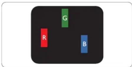
One lit red, green or blue sub pixel.
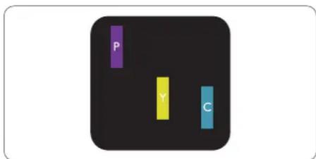
Two adjacent lit sub pixels:
- Red + Blue = Purple
- Red + Green = Yellow
- Green + Blue = Cyan (Light Blue)

Three adjacent lit sub pixels (one white pixel).
Note
A red or blue bright dot must be more than 50 percent brighter than neighboring dots while a green bright dot is 30 percent brighter than neighboring dots.
Black Dot Defects
Black dot defects appear as pixels or sub pixels that are always dark or 'off'. That is, a dark dot is a sub-pixel that stands out on the screen when the monitor displays a light pattern. These are the types of black dot defects.
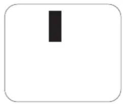
Proximity of Pixel Defects
Because pixel and sub pixels defects of the same type that are near to one another may be more noticeable, AOC also specifies tolerances for the proximity of pixel defects.

Pixel Defect Tolerances
In order to qualify for repair or replacement due to pixel defects during the warranty period, a Monitor panel in a AOC panel monitor must have pixel or sub pixel defects exceeding the tolerances listed in the web manual.
| BRIGHT DOT DEFECTS ACCEPTABLE LEVEL | |
| 1 lit subpixel | 2 |
| 2 adjacent lit subpixels | 1 |
| 3 adjacent lit subpixels (one white pixel) | 0 |
| Distance between two bright dot defects* | >=15mm |
| Total bright dot defects of all types | 2 |
| BLACK DOT DEFECTS | ACCEPTABLE LEVEL |
| 1 dark subpixel 5 or fewer | |
| 2 adjacent dark subpixels 2 or fewer | |
| 3 adjacent dark subpixels ≤1 | |
| Distance between two black dot defects* >=15mm | |
| Total black dot defects of all types 5 or fewer | |
| TOTAL DOT DEFECTS ACCEPTABLE LEVEL | |
| Total bright or black dot defects of all types 5 or fewer |
Note
*: 1 or 2 adjacent sub pixel defects = 1 dot defect.
Preset Display Modes
| STANDARD RESOLUTION | HORIZONTAL FREQUENCY(kHz) | VERTICAL FREQUENCY(Hz) | |
| VGA | 640x480@60Hz 31.47 59.94 | ||
| 640x480@72Hz 37.86 72.81 | |||
| 640x480@75Hz 37.50 75.00 | |||
| SVGA | 800x600@56Hz 35.16 56.25 | ||
| 800x600@60Hz 37.88 60.32 | |||
| 800x600@72Hz 48.08 72.19 | |||
| 800x600@75Hz 46.88 75.00 | |||
| XGA | 1024x768@60Hz | 48.36 60.00 | |
| 1024x768@70Hz 56.48 | 70.07 | ||
| 1024x768@75Hz | 60.02 75.03 | ||
| SXGA | 1280x1024@60Hz | 63.89 60.02 | |
| 1280x1024@75Hz 79.98 | 75.03 | ||
| WXGA+ 1440x900@60Hz 55.94 59.89 | |||
| WSXGA 1680x1050@60Hz 65.29 59.954 | |||
| FHD | 1920x1080@60Hz 67.50 | 60.00 | |
| 1920x1080@75Hz 83.93 | 75.00 | ||
| QHD | 2560x1440@60Hz 88.86 | 60.00 | |
| 2560x1440@75Hz 111.08 | 75.00 | ||
| 2560x1440@100Hz 148.50 | 100.00 | ||
| IBM MODES | |||
| DOS 720x400@70Hz 31.47 70.09 | |||
| MAC MODES | |||
| VGA 640x480@67Hz 35.00 66.67 | |||
| SVGA 832x624@75Hz 49.73 74.55 | |||
| XGA 1024x768@75Hz 60.24 74.93 | |||
Pin Assignments

19-Pin Color Display Signal Cable
| Pin No. | Signal Name Pin No. | Signal Name | Pin No. Signal Name | ||
| 1. TMDS | Data 2+ 9. TMDS Data 0- 17. DDC/CEC Ground | ||||
| 2. TMDS | Data 2 Shield 10. TMDS Clock + 18. +5V Power | ||||
| 3. TMDS | Data 2- 11. TMDS Clock Shield 19. Hot Plug Detect | ||||
| 4. TMDS | Data 1+ 12. TMDS Clock- | ||||
| 5. TMDS | Data 1Shield 13. CEC | ||||
| 6. TMDS | Data 1- 14. Reserved (N.C. on device) | ||||
| 7. TMDS | Data 0+ 15. SCL | ||||
| 8. TMDS | Data 0 Shield 16. SDA | ||||

20-Pin Color Display Signal Cable
| Pin No. Signal Name Pin No. Signal Name | ||
| 1. ML_Lane 3 (n) 11. GND | ||
| 2. GND 12. ML_Lane 0 (p) | ||
| 3. ML_Lane 3 (p) 13. CONFIG1 | ||
| 4. ML_Lane 2 (n) 14. CONFIG2 | ||
| 5. GND 15. AUX_CH(p) | ||
| 6. ML_Lane 2 (p) 16. GND | ||
| 7. ML_Lane 1 (n) 17. AUX_CH(n) | ||
| 8. GND 18. Hot Plug Detect | ||
| 9. ML_Lane 1 (p) 19. Return DP_PWR | ||
| 10. ML_Lane 0 (n) 20. DP_PWR |
Plug and Play
Plug & Play DDC2B Feature
This monitor is equipped with VESA DDC2B capabilities according to the VESA DDC STANDARD. It allows the monitor to inform the host system of its identity and, depending on the level of DDC used, communicate additional information about its display capabilities.
The DDC2B is a bi-directional data channel based on the I2C protocol. The host can request EDID information over the DDC2B channel.
- LCD MONITOR USER MANUAL Q32V5E
- SAFETY
- SETUP
- ADJUSTING
- TROUBLESHOOT
- SPECIFICATION
- NATIONAL CONVENTIONS
- POWER
- INSTALLATION
- CLEANING
- OTHER
- SET-UP STAND & BASE
- ADJUSTING VIEWING ANGLE
- NOTE
- WARNING
- CONNECTING THE MONITOR
- CONNECT TO PC
- WALL MOUNTING
- GRAPHICS CARDS
- PROCESSORS
- HOTKEYS
- POWER/MENU/ENTER
- SOURCE/UP
- PRESET MODE/LEFT
- BRIGHTNESS/RIGHT
- VOLUME/DOWN
- OSD SETTING
- NOTES
- LED INDICATOR
- AOC MONITORS PANEL PIXEL DEFECT POLICY
- PIXELS AND SUB PIXELS
- TYPES OF PIXEL DEFECTS
- BRIGHT DOT DEFECTS
- BLACK DOT DEFECTS
- PROXIMITY OF PIXEL DEFECTS
- PIXEL DEFECT TOLERANCES
- PIN ASSIGNMENTS
- PLUG AND PLAY
- PLUG & PLAY DDC2B FEATURE
Brand : AOC
Model : Q32V5E
Category : Monitor