
LP441W - Printer OKI - Free user manual and instructions
Find the device manual for free LP441W OKI in PDF.
| Product Type | Portable thermal label printer |
| Brand | OKI |
| Model | LP441W |
| Power Supply | Rechargeable lithium-ion battery (charges via optional charger or AC adapter) or optional AC adapter |
| Interface | RS-232C, IrDA, Bluetooth, wireless LAN (Wi-Fi optional) |
| Label Format | Label rolls, continuous or batch mode |
| Printing Modes | Continuous mode, automatic or manual batch mode |
| Online Commands | Compatible with Petit lapin or SBPL (selectable via DIP switch) |
| Battery Capacity | Approximately 300 charge cycles |
| Charge Time | Approximately 2.5 h with charger, 5 h with AC adapter |
| Maintenance | Clean the print head, platen, and roller with an alcohol-dampened cloth |
| Safety | Compliant with VCCI class B, water protection (optional waterproof case) |
| Spare Parts | Battery, charger, AC adapter, protective case |
| Included Accessories | Shoulder strap, paper guide, covers |
| Intended Use | Barcode label printing |
Frequently Asked Questions - LP441W OKI
User questions about LP441W OKI
0 question about this device. Answer the ones you know or ask your own.
Ask a new question about this device
Download the instructions for your Printer in PDF format for free! Find your manual LP441W - OKI and take your electronic device back in hand. On this page are published all the documents necessary for the use of your device. LP441W by OKI.
USER MANUAL LP441W OKI
natural_image
Line drawing of a portable projector with front panel and internal ports (no text or symbols)English 3
Français 39
Español 75
Português 113
Introduction
This manual is intended to help you become familiar with the basic operation of Petit lapin the barcode printer in a short time.
Please read this manual carefully to make full use of the functions of Petit lapin.
Notes
- Reproduction of all or part of this manual is prohibited without permission of the copyright owner.
- The information in this manual is subject to change without notice.
- If you find any ambiguous or erroneous information in this manual, please contact your nearest dealer or service center.
Warning
This is a Class B product based on the standard of the Voluntary Control Council for Interference by Information Technology Equipment (VCCI). If this equipment is used in a domestic environment, radio disturbance may arise. When such trouble occurs, the user may be required to take corrective actions.
Caution! This printer can be damaged by exposure to water. Whenever you use it outdoors, or in any area where it might be exposed to water, always place it in the optional waterproof case (OKI # 70061202) to protect it from damage.
For Customers Using the Bluetooth or Wireless Communication Models
Notes on Radio Wave
This product has been approved of adaptability in the technological standard based on Radio Law. Therefore, use of this product does not require a license for radio station. This product is limited for use in Japan only.
The following behavior may result in judicial punishment.
• Disassembling/modifying this product
- Removing the certificate label (serial number seal) attached on this product
Use of this product in the following place may shorten the communication distance or disable communication.
Near microwave oven, place where static electricity or radio failure is caused, or near wireless LAN equipment.

Bluetooth™
“Bluetooth” is a trademark of Bluetooth SIG, Inc., USA. We use the mark with a license by the said company.
Before using wireless LAN interface, be sure to make all the settings related to the security of wireless LAN equipment in accordance with the manual supplied with the equipment.
Table of Contents
Unpacking 6
Parts Name 7
Name and Function of Controls 9
Before Starting 10
Charging the Battery Pack 10
Installing and removing the Battery Pack .... 13
Using AC Adapter 15
Setting Labels 16
Continuous mode 16
Dispense mode....18
Turning Printer On 21
Test Printing.... 22
Using RS-232C Interface. 23
Using IrDA Interface 24
Using Bluetooth Interface or Wireless LAN Interface ..... 25
Printing....26
Daily Maintenance.... 28
Operation Modes. 30
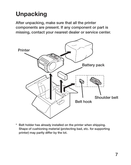
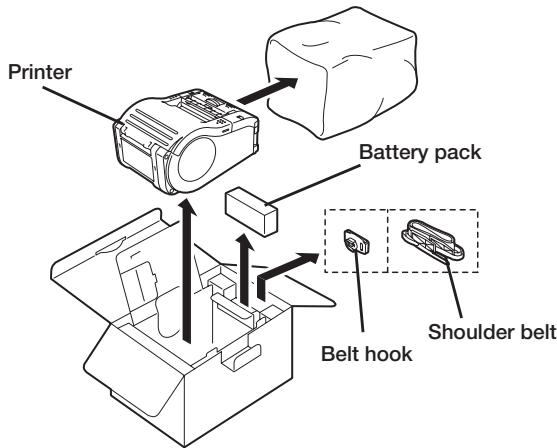
Unpacking
After unpacking, make sure that all the printer components are present. If any component or part is missing, contact your nearest dealer or service center.
* Belt holder has already installed on the printer when shipping. Shape of cushioning material (protecting bad, etc. for supporting printer) may partly differ by the lot.
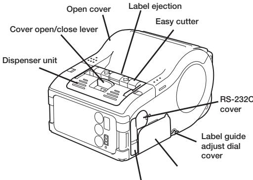
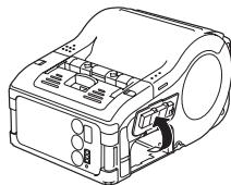
Parts Name
Battery cover Cover for DC input jack
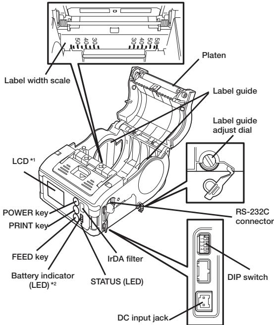
^1 Operation panel with LCD is built in the wireless LAN interface model only (for manufacture option).
^2 Operation panel with LCD for the wireless LAN interface model has CHARGE LED (for manufacture option).
Name and Function of Controls
RS-232C Interface: Connects to PC or handy terminal.
RS-232C cover: Cover for RS-232C connector.
Open cover: Opened for setting labels.
Cover Open/Close lever: Used to open or close the cover.
Easy cutter: Cuts printed labels.
IrDA filter: Contains IrDA sensor and emitter.
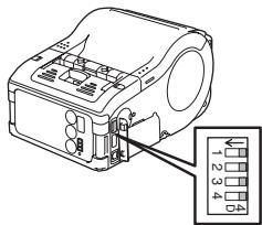
DIP switch: Sets the operation mode of the printer. (See page 35.)
Dispenser unit: Moved to select Dispense mode.
POWER key: Turns on/off the printer.
Battery cover: Cover for special battery pack.
Battery indicator (LED): Indicates the remaining amount of battery of the printer.
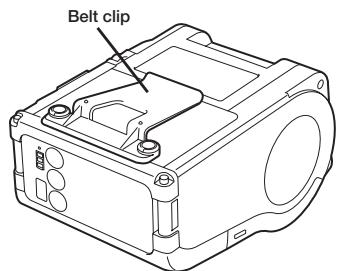
Belt clip: Used when hanging the printer on your belt.
* Do not hang the printer on to anything but a belt.
Label guide: Set to meet the size of the label used.
Label guide adjust dial: Adjusts the label guide to the width of the label used.
Label guide adjust dial cover: Cover for label guide adjust dial.
Label ejection: Ejects the printed label.
Label width scale: Indicates the width of label used.
DC input jack: Connects to AC adapter.
Cover for DC input jack: Cover for DC input terminal and DIP switch.
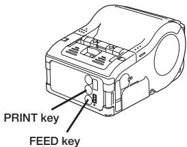
FEED key: Press to feed label.
PRINT key: Sets the printer online or offline.
STATUS (LED): Indicates the status of the printer. (See pages 29 to 34.)
Before Starting
Charging the Battery Pack
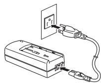
- Using the battery charger (option) to charge the battery pack
Follow the steps below to charge the battery pack using the battery charger.
① Plug one end of the power cord to the battery charger and the other to the wall outlet. (POWER lamp lights red.)
② Put the battery pack on the battery charger and then slide it in the direction of the arrow.
Charging starts and the CHARGE lamp lights orange. When charging is completed (fully charged), the CHARGE lamp goes off. In case of five-socket charger, charging starts and the CHARGE lamp lights orange. When charging is completed (fully charged), the CHARGE lamp lights green.
natural_image
Line drawing of a battery connected to an electrical outlet (no text or symbols)
natural_image
Technical line drawing of a device with a component inserted into a housing (no text or symbols)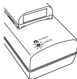
natural_image
Line drawing of a closed book with a handle and spout, no text or symbols present③ After charging, remove the battery pack from the charger.
Slide the battery pack in the opposite direction of step (2) to remove the battery back.
Notice
- If the POWER lamp does not light at the start of charging, check the power cord connection.
- If the CHARGE lamp does not light at the start of charging, make sure the battery pack is firmly mounted to the battery charger. Poor mounting of the battery pack may result in poor charging.
- When the fully charged battery pack is placed on the battery charger, the CHARGE lamp goes on and then off.
In case of five-socket charger, the CHARGE lamp lights green. - When charging a battery pack that has not been used for a long time, the CHARGE lamp may blink for a while. This does not indicate an error. You can continue charging.
- The battery pack can be recharged by about 300 times (when used in normal temperature). If the battery is fully charged but runs out very soon, renew the battery pack.
Charging Time
It takes about 2.5 hours for the battery pack to reach full charge from a fully discharged state.
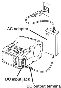
- Using the AC adapter (option) to charge the battery pack
The battery pack can be charged while it is mounted in the printer.
① Open the cover for DC input jack and insert the DC output terminal.
② Plug the AC adapter to the wall outlet.
Charging starts and the battery indicator lights red. When charging is completed (fully charged), the battery indicator goes off.
In the case of the LCD built-in wireless LAN interface model, CHARGE LED lights
red when charging starts and is completed (fully charged), the CHARGE LED goes off.
Charging Time
It takes about 5 hours for the battery pack to reach full charge from a fully discharged state.
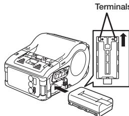
Installing and removing the Battery Pack
① Open the battery cover.
natural_image
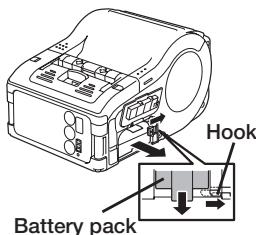
Technical line drawing of a mechanical device with internal components and mounting holes (no text or symbols)② Insert the battery pack while pressing and holding the gray hook and close the battery cover.
Insert the battery pack with the terminal side toward the printer.
③ When removing the battery, press and hold the gray hook and then pull the tape.
* Make sure to turn the printer power off when removing or replacing the battery. When the printer is turned off, the STATUS LED goes off. Do not remove the battery while the STATUS LED is on. Remove the battery when the STATUS LED is off. (See page 20.)
* If you turning off the printer otherwise, the information stored in the printer may not be updated.
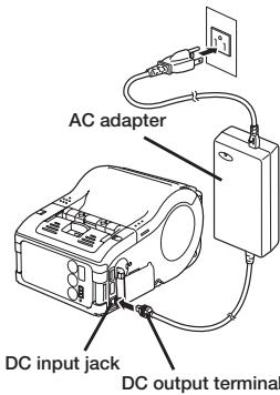
Using AC Adapter
Follow the procedure below to use the printer with the AC adapter (option).
① Open the cover for DC input jack and insert the DC output terminal.
② Plug the AC adapter to the wall outlet.
* Be sure to turn the printer power off when removing the DC output terminal of AC adapter or disconnecting the power source.
* If you turning off the printer otherwise, the information stored in the printer may not be updated.
* A battery pack is unnecessary when an AC adapter is used. If a battery pack and an AC adapter are being used at the same time, the printer starts charging (when a battery is not fully charged) or the battery indicator goes off (when a battery is fully charged).
Setting Labels
The method of setting label may vary depending on the print mode.
Continuous mode
(See figure in page 29.)
natural_image
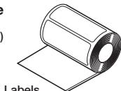
Illustration of a rolled-up sheet of paper with no visible text or symbols
natural_image
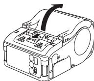
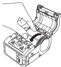
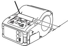
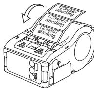
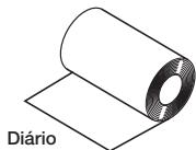
Illustration of a rolled-up sheet of paper with a circular hole, labeled 'Journal' at the bottom (no other text or symbols)① Slide the Cover Open/Close lever in the direction of arrow to open the cover.
If you are using the printer in Dispense mode, lifting the change lever, slide the dispenser unit until stops (see page 19).
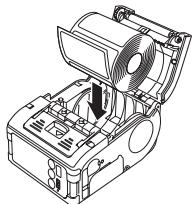
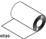
② Place the label to the printer.
Pay attention to the direction of the label roll.
natural_image
Technical line drawing of a mechanical device with no visible text or symbols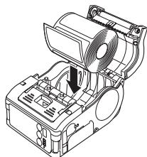
natural_image
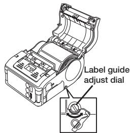
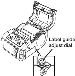
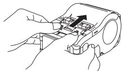
Technical line drawing of a mechanical device with fan and housing (no text or symbols)③ Open the label guide adjust dial cover and turn the dial till the label guide fits with label roll.
Turn the label roll lightly by the hand and confirm that it rotates smoothly.
If a drags is felt, paper may not be fed correctly. Return the dial for adjustment. When using the paper of the same width as that used previously, adjustment of the label guide is not necessary.
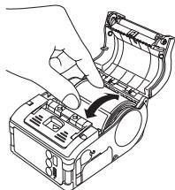
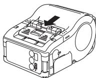
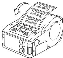
④ Close the cover after confirming that the leading edge of the label is outside the printer.
natural_image
Line drawing of a hand inserting a component into a device housing (no text or symbols)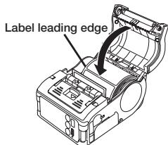
This completes the label setting in continuous mode.
Dispense mode
(See figure in page 29.)
① Slide the Cover Open/Close lever in the direction of arrow to open the cover.
If you are using the printer in Dispense mode, lifting the change lever, slide the dispenser unit until stops.
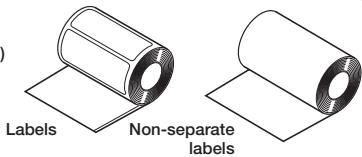
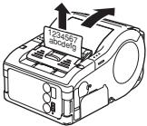
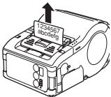
② Peel the first label on the top of the label.
This step is unnecessary when a non-separate label is used.
natural_image
Line drawing of a car airbag with control panel and ventilation slots (no text or symbols)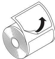
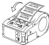
natural_image
Diagram of a rolled-up sheet with an arrow indicating clockwise rotation (no text or symbols)③ Set the label to the printer.
Pay attention to the direction of the label roll.
natural_image
Technical line drawing of a mechanical device with a fan and internal components (no text or symbols)4 Open the label guide adjust dial cover and turn the dial till the label guide fits with label roll.
Turn the label roll lightly by the hand and confirm that it rotates smoothly.
If a drags is felt, paper may not be fed correctly. Return the dial for adjustment. When using the paper of the same width as that used previously, adjustment of the label guide is not necessary.
natural_image
Line drawing of a hand inserting a device into a device housing (no text or symbols visible)⑤ Close the cover after confirming that the leading edge of the label is outside the printer (more than 10 mm).
When using a non-separate label, press FEED key to feed a piece of label and pull the label upward to cut it along the perforation.
If the label is jammed, retry label setting procedure.
Label leading edge
natural_image
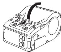
Technical line drawing of a mechanical device with no visible text or symbols⑥ Slide the dispenser unit until it stops.
natural_image
Illustration of hands assembling a device with an arrow indicating motion (no text or symbols)This completes the label setting in the Dispense mode.
- To changing Dispense mode to continuous mode Lifting the change lever, slide the dispenser unit until stops.
natural_image
Line drawing of a car air conditioner unit with no visible text or symbolsTurning Printer On
After the procedure mentioned before has been finished, try to turn the printer power on and off.
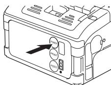
① Press and hold the POWER key. When the STATUS LED lights green, release the key.
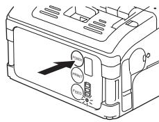
② Press and hold the POWER key again. When he STATUS LED goes off, release the key.
Test Printing
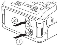
1 Pressing and holding the FEED key, set the POWER key. The printer enters the test mode. Press the FEED key again to start test printing.
② Verify the following using the output of the test printing.
- There is no chipped character.
- Print condition is good.
In the test printing, the battery residual is indicted by ( for full charge).
When the battery indicates , charge the battery.

* If any fault is detected, contact the store you bought the printer, dealer, or service center.
Using RS-232C Interface
Use the following procedure to print by connecting to a PC or a handy terminal through an RS-232C cable option.
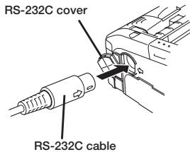
① Open the RS-232C cover.
② Plug one end of the RS-232C cable into the connector firmly.
Be sure that the arrow mark on the connector of the RS-232C cable matches with the arrow mark by the side of the printer connector.
③ Plug the other end of the RS-232C cable to the connector of the PC or handy terminal.
For the information on the connector of the PC
or handy terminal, refer to the manual supplied with the PC.
Using IrDA Interface
Use the following procedure to print through IrDA interface.
① Place the printer within the distance of 20 cm from the PC or handy terminal to communicate through IrDA.
② Adjust the printer position to let the PC or the handy terminal in the range of 30^ from the center of the IrDA filter (a corn area shown below).
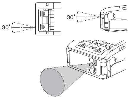
The distance available for IrDA communication is a maximum of 15 to 20 cm.
* This distance may vary depending on the environment of use or the party to communicate with. Especially under direct sun light or in the environment exposed to strong illumination, communication may be disabled. In such a case, block the strong light not to enter the IrDA filter or make the PC contact the IrDA filter.
Using Bluetooth Interface or Wireless LAN Interface
Note that when printing with Bluetooth interface or wireless LAN interface, the distance between the printer and the host may differ depending on the environment of use and the performance of the PC or handy terminal used.
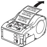
Printing
① Allow data transmission from the PC.
② When printing is finished, pinch either right or left corner of the label top and pull it with arrow direction.
* The number of sheets you can print in this mode differs with that in the continuous or peel mode.
* When the non-separate label is cut at a place other than perforation and next printing is not available, follow the procedure in page 35.
When next printing is not available
① Press the PRINT key in the online state to set the printer off line state (STATUS LED goes off).
② Press the FEED key to feed label.
③ When the feeding stops, cut the label by pulling the label top with arrow direction.
4 Press the PRINT key to return to the online state (STATUS LED lights green).

Daily Maintenance
Use the following procedure after turning the printer off and removing the battery pack.
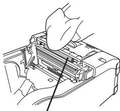
Cleaning thermal head
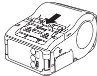
① Slide the cover Open/Close lever and open the Open cover.
If you are using the printer in Dispense mode, lifting the change lever, slide the dispenser unit until it stops (see page 19).
② Wipe off the dirt using cloth wetted (soaked) in alcohol.
* Never use thinner, benzene, or kerosene.
natural_image
Technical line drawing of a mechanical device with no visible text or symbols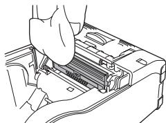
natural_image
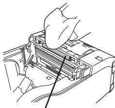
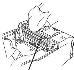
Line drawing of a hand inserting a spring into a device casing (no text or symbols)Cleaning the platen and peel roller
① Slide the cover Open/Close lever and open the Open cover.
If you are using the printer in Dispense mode, lifting the change lever, slide the dispense unit until stops.
② Wipe off the dirt using cloth wetted (soaked) in alcohol.
* Never use thinner, benzene, or kerosene.

natural_image
Line drawing of a car air conditioner unit with no visible text or symbols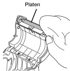
natural_image
Line drawing of hands inserting a device into a box (no text or symbols visible)Dispense roller
Operation Modes
The printer can operate in two modes: continuous mode and dispense mode. In either mode, test printing and online printing are available.
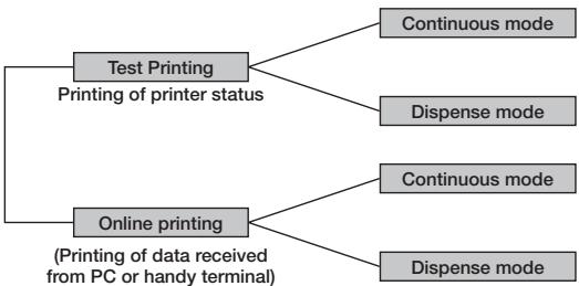
flowchart
graph TD
    A["Test Printing\nPrinting of printer status"] --> B["Continuous mode"]
    A --> C["Dispense mode"]
    D["Online printing\n(Printing of data received from PC or handy terminal)"] --> E["Continuous mode"]
    D --> F["Dispense mode"]
| Continuous mode | Dispense mode (Labels) | Dispense mode (Non-separate labels |
 |  |  |
* You can select Dispense mode (Non-separate labels) by using the printer setting tool.
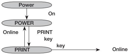
Normal Operation
flowchart
graph TD
    A["Power"] -->|On| B["POWER"]
    B -->|Online| C["PRINT"]
    C -->|key| D["Online"]
    B <-->|PRINT key| C
LED indication in normal operation is as shown below.
| Operating state | STATUS (LED) |
| At the start of normal printing | Light (Orange) |
| Online state | Light (Green) |
| Offline state | Not lit |
* Battery indicator is lit even in offline state.
Power Save Mode
- Sleep Mode: STATUS (LED) blinks (Green) at intervals of 4 seconds. In offline state, STATUS (LED) goes off. Battery indicator is lit even in offline state. When you do not operate for 5 seconds, the printer enters the Sleep mode (Standby state). When you press the PRINT key or FEED key, when the printer receives data, or when you open and close the Open cover, the printer returns to the normal state.
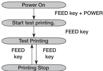
Test Print Mode (FEED key + Power On)
flowchart
graph TD
    A["Power On"] --> B["Start test printing."]
    B --> C["Test Printing"]
    C --> D["FEED key"]
    C --> E["FEED key + POWER"]
    C --> F["FEED Print Stop"]
LED indication at the test print mode is as shown below.
| Operating state | STATUS (LED) |
| At the start of test print mode | Light (Orange) |
| Test print starting | Blink (Green) |
| In test printing | Light (Green) |
| Printing stop | Not lit |
Dispense Mode
Specifying dispense mode
| Type | Operation | Default |
| Auto print | Prints one label after receiving data and waits for peeling. After peeling a label, automatically prints next label. | Manual print |
| Manual print | Prints one label after receiving data and enters offline state. Pressing the PRINT key allows next label to be printed. After printing the specified number of labels, printing terminates. No printing occurs even when the PRINT key is pressed. |
Dispense mode designation change
Change of dispense mode setting is available with the designation of DSW and key at the printer power on. The setting is valid after turning the printer off.
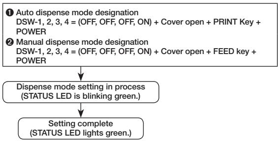
flowchart
graph TD
    A["1 Auto dispense mode designation\nDSW-1, 2, 3, 4 = (OFF, OFF, OFF, ON) + Cover open + PRINT Key + POWER"] --> B["2 Manual dispense mode designation\nDSW-1, 2, 3, 4 = (OFF, OFF, OFF, ON) + Cover open + FEED key + POWER"]
    B --> C["Dispense mode setting in process\n(STATUS LED is blinking green.)"]
    C --> D["Setting complete\n(STATUS LED lights green.)"]
Note: When terminating the dispense mode designation, confirm that the STATUS LED lights green and then turn the printer power off.
Head Check Setting Mode
In the Head Check Setting mode, head checking can be implemented in two check ranges: normal print area and barcode print area.
Head check feature can be verified for presence or absence and head check range can be set in accordance with DSW setting, status of pressing key, and status of cover at the time of printer power on.
DIP switch setting
| DSW-1 | DSW-2 | DSW-3 | DSW-4 | |
| (A) | OFF | ON | OFF | ON |
| (B) | ON | OFF | OFF | ON |
| DSW setting | Status of key and cover | Function |
| (A) | PRINT key + Cover open | Sets head check range to print area. |
| FEED key + Cover open | Sets head check function to Disable. | |
| (B) | PRINT key + Cover open | Sets head check range to only barcode print area. |
| FEED key + Cover open | Sets head check function to Disable. |
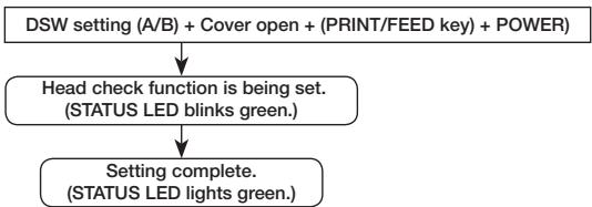
flowchart
graph TD
    A["DSW setting (A/B) + Cover open + (PRINT/FEED key) + POWER"] --> B["Head check function is being set.<br>(STATUS LED blinks green.)"]
    B --> C["Setting complete.<br>(STATUS LED lights green.)"]
Note: You can check the current setting with the test printout (see page 21). When terminating head check setting, confirm that STATUS LED lights green and then turn the printer power off.
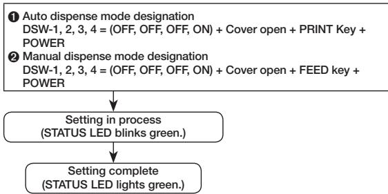
Online Command Setting Mode
Online Command Designation
| Type | Operation | Default |
| Petit lapin compatible command designation | Uses online command as Petit lapin standard command. | SBPL command designation |
| SBPL command designation | Uses online command as SBPL command. |
Online command designation change
Change of online command designation is available with the designation of DSW and key at the printer power on. The setting is valid after turning the printer off.
flowchart
graph TD
    A["1 Auto dispense mode designation\nDSW-1, 2, 3, 4 = (OFF, OFF, OFF, ON) + Cover open + PRINT Key + POWER\n2 Manual dispense mode designation\nDSW-1, 2, 3, 4 = (OFF, OFF, OFF, ON) + Cover open + FEED key + POWER"] --> B["Setting in process\n(STATUS LED blinks green.)"]
    B --> C["Setting complete\n(STATUS LED lights green.)"]
Note: You can check the current setting with the test printout (see page 21). When terminating the online command designation, confirm that the STATUS LED lights green and then turn the printer power off.
DIP Switch
Setting DIP switch
① Turn the printer power off.
② Open the DIP switch cover.
③ Change the position of the switch you want to change using a pointed tool such as the tip of ball-point pen.
DIP Switch Setting
| DIP switch | Cover | Key | Starting mode | |||||
| 1 | 2 | 3 | 4 | FEED | Interface | Description | ||
| OFF | OFF | OFF | OFF | Close | OFF | OFF | RS-232C | Normal print mode |
| Close | OFF | ON | — | User test print mode | ||||
| OFF | OFF | ON | ON | Close | OFF | OFF | RS-232C | HEX dump mode |
| OFF | OFF | OFF | ON | Open | ON | OFF | — | Auto peeling mode |
| Open | OFF | ON | — | Manual print mode | ||||
| OFF | ON | OFF | OFF | Close | OFF | OFF | Bluetooth interface/Wireless interface | Normal print mode |
| Close | OFF | ON | — | User test print mode | ||||
| OFF | ON | OFF | ON | Open | ON | OFF | — | Head check (print area) designation |
| Open | OFF | ON | — | Head check designation clear | ||||
| OFF | ON | ON | ON | Open | OFF | OFF | Bluetooth interface/Wireless interface | HEX dump mode |
| Open | ON | OFF | — | CRC check enable designation | ||||
| Open | OFF | ON | — | CRC check disenable designation | ||||
| ON | OFF | OFF | OFF | Close | OFF | OFF | IrDA interface | Normal print mode |
| Close | OFF | ON | — | Test print mode | ||||
| ON | OFF | ON | ON | Close | OFF | OFF | IrDA interface | HEX dump mode |
DIP Switch Setting (cont'd)
| DIP switch | Cover | Key | Starting mode | |||||
| 1 | 2 | 3 | 4 | FEED | Interface | Description | ||
| ON | OFF | OFF | ON | Open | ON | OFF | Head check (Barcode print area) designation | |
| Open | OFF | ON | — | Head check clear | ||||
| ON | ON | ON | ON | Open | ON | OFF | — | Online command designation (Petit lapin compatible) |
| Open | OFF | ON | — | Online command designation (SBPL command) | ||||
Introduction
© 2010 Oki Data Americas, Inc.
Mode distribution 54
natural_image
Diagram of a device with an open electrical outlet connected to a cable, showing wiring and components (no text or symbols)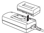
natural_image
Technical line drawing of a device with a base and connector (no text or symbols)
natural_image
Line drawing of a closed book with a handle and spines, no text or symbols presentnatural_image
Technical line drawing of a mechanical device with internal components (no text or symbols)natural_image
Technical line drawing of a printer with an attached circuit board (no text or symbols)natural_image
Line drawing of a car front panel with control buttons and a black cable (no text or symbols)
natural_image
Technical line drawing of a mechanical device with fan and housing (no text or symbols)natural_image
Line drawing of a mechanical device with no visible text or symbolsnatural_image
Diagram of a rolled-up sheet with a curved arrow indicating rotation (no text or symbols)natural_image
Technical line drawing of a mechanical device with internal components and a fan (no text or symbols)natural_image
Illustration of a hand inserting a device into a housing (no text or symbols visible)natural_image
Technical line drawing of a mechanical device with no visible text or symbolsnatural_image
Illustration of hands assembling a device with a handle (no text or symbols)natural_image
Technical line drawing of a mechanical device with internal components and a directional arrow (no text or symbols)
Test d'impression
natural_image
Diagram of a toaster with a cylindrical lens, showing no text or symbolsnatural_image
Line drawing of a car air conditioner unit with no visible text or symbols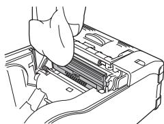
natural_image
Line drawing of a hand inserting a component into a device (no text or symbols visible)natural_image
Line drawing of a car air vent with a directional arrow indicating airflow or movement (no text or symbols)
natural_image
Line drawing of hands installing or adjusting a mechanical component with a cable (no text or symbols visible)Introducción
© 2010 Oki Data Americas, Inc.
natural_image
Line drawing of a battery connected to an electrical outlet (no text or symbols)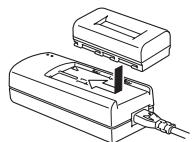
natural_image
Technical line drawing of a device with a base and internal components (no text or symbols)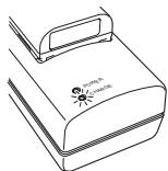
natural_image
Line drawing of a closed book with a handle and spout, no text or symbols presentnatural_image
Technical line drawing of a mechanical device with internal components and mounting holes (no text or symbols)natural_image
Diagram of a cylindrical object with a flat base, showing internal structure (no text or symbols)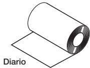
natural_image
Diagram of a rolled document or sheet with a circular hole, labeled 'Diario' at the bottom (no other text or symbols)Etiquetas
natural_image
Technical line drawing of a mechanical device with no visible text or symbols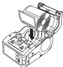
natural_image
Technical line drawing of a mechanical device with fan and housing (no text or symbols)natural_image
Technical line drawing of a cylindrical mechanical component with a flat sheet underneath (no text or symbols)Etiquetas
natural_image
Diagram of a rolled sheet with visible texture and pattern, no text or symbols presentEtiquetas perforadas
natural_image
Line drawing of a mechanical device with no visible text or symbolsnatural_image
Illustration of a rolled-up sheet with a curved arrow indicating rotation (no text or symbols)natural_image
Technical line drawing of a mechanical device with a fan and internal components (no text or symbols)natural_image
Illustration of a hand inserting a component into a device housing (no text or symbols visible)natural_image
Technical line drawing of a mechanical device with no visible text or symbolsnatural_image
Illustration of hands assembling a device with an arrow indicating motion (no text or symbols)natural_image
Line drawing of a car air conditioner unit with no visible text or symbolsImpresión de prueba

natural_image
Diagram of a device emitting a cone-shaped light beam, showing no text or symbolsnatural_image
Line drawing of a mechanical device with internal components and an arrow indicating a specific part (no text or symbols present)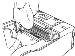
natural_image
Line drawing of a hand inserting a component into a device (no text or symbols visible)natural_image
Line drawing of a car air conditioner unit with no visible text or symbols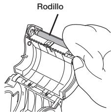
natural_image
Hand inserting a device into a computer case (no text or symbols visible)Dispense roller
© 2010 Oki Data Americas, Inc.
natural_image
Diagram of an electrical outlet connected to a device with cables (no text or symbols)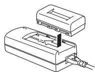
natural_image
Technical line drawing of a device with a rectangular housing and cable connector (no text or symbols)
natural_image
Line drawing of a closed book with a handle and cover (no text or symbols visible)natural_image
Technical line drawing of a mechanical device with internal components (no text or symbols)natural_image
Technical line drawing of a rolled cylindrical component with a flat base, labeled 'metas' (no text or symbols on the diagram itself)Etiquetas
natural_image
Diagram of a rolled sheet labeled 'Diário' with no other text or symbolsnatural_image
Line drawing of a mechanical device with no visible text or symbols② Coloque as etiquetas na impressora.
natural_image
Technical line drawing of a mechanical device with fan and internal components (no text or symbols)natural_image
Technical illustration of a mechanical device with an inset showing a disassembly or assembly (no text or symbols present)natural_image
Illustration of a hand inserting a device into a housing (no text or symbols visible)natural_image
Illustration of a rolled paper or sheet with a circular hole, no text or symbols presentnatural_image
Technical line drawing of a mechanical component with no visible text or symbolsnatural_image
Diagram of a rolled-up sheet with a curved arrow indicating rotation or movement (no text or symbols)③ Coloque as etiquetas na impressora.
natural_image
Technical line drawing of a mechanical device with a fan and internal components (no text or symbols)natural_image
Illustration of a hand inserting a cable into a device housing (no text or symbols visible)natural_image
Technical line drawing of a mechanical device with no visible text or symbolsnatural_image
Illustration of hands assembling or adjusting a mechanical component with an arrow indicating motion (no text or symbols present)natural_image
Technical line drawing of a mechanical device with internal components and a directional arrow (no text or symbols)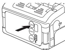
Impressão de teste
natural_image
Diagram of a device with a cylindrical lens and control panel, no text or symbols presentnatural_image
Line drawing of a car air conditioner unit with no visible text or symbols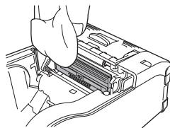
natural_image
Line drawing of a hand inserting a device into a rack (no text or symbols visible)Limpeza do cilindro e do rolete do papel
① Deslize a alavanca de abrir/fechar a tampa e abra a tampa.
natural_image
Line drawing of a mechanical device with internal components and a directional arrow (no text or symbols)natural_image
Hand inserting a component into a device housing (no text or symbols visible)rolo de dispensa
Modos de operação
- Introduction
- Notes
- Warning
- For Customers Using the Bluetooth or Wireless Communication Models
- Notes on Radio Wave
- Bluetooth™
- Table of Contents
- Unpacking
- Parts Name
- Name and Function of Controls
- Before Starting
- Charging the Battery Pack
- Notice
- Charging Time
- Installing and removing the Battery Pack
- Using AC Adapter
- Setting Labels
- Continuous mode
- Dispense mode
- Turning Printer On
- Test Printing
- Using RS-232C Interface
- Using IrDA Interface
- Using Bluetooth Interface or Wireless LAN Interface
- Printing
- When next printing is not available
- Daily Maintenance
- Cleaning thermal head
- Cleaning the platen and peel roller
- Operation Modes
- Normal Operation
- Power Save Mode
- Dispense mode designation change
- Head Check Setting Mode
- Online Command Setting Mode
- Online Command Designation
- Online command designation change
- DIP Switch
- Setting DIP switch
- Test d'impression
- Introducción
- Impresión de prueba
- Impressão de teste
- Limpeza do cilindro e do rolete do papel
- Modos de operação
Brand : OKI
Model : LP441W
Category : Printer