
B6200N - Laser printer OKI - Free user manual and instructions
Find the device manual for free B6200N OKI in PDF.

| Product type | Monochrome laser printer |
| Brand | OKI |
| Model | B6200N |
| Dimensions (W × D × H) | Approximately 300 × 400 × 400 mm |
| Weight | 20.4 kg (with consumables) |
| Power supply | 110 V or 220-240 V, 50/60 Hz |
| Duplex printing | Optional (duplex unit available) |
| Standard paper capacity | 400 sheets (tray 1: 150 sheets, tray 2: 250 sheets) |
| Print resolution | 600 × 600 dpi |
| Print speed | Up to 20 pages per minute |
| Standard memory | 64 MB (expandable to 512 MB) |
| Connectivity | Parallel, USB, serial; network optional |
| Main functions | Multi-page printing, watermark, poster, booklet, transparency separation, favorites |
| Advanced functions | Secure printing, delayed printing, proof printing (require optional hard disk) |
| Maintenance and cleaning | Clean ventilation areas with a dry cloth; do not use solvents |
| Safety | Do not open covers secured by screws; disconnect before servicing |
| Spare parts and repairability | Drum-toner cartridge, paper trays, duplex unit, hard disk, memory |
| General information | 1-year warranty; technical support 1-800-OKI-DATA |
Frequently Asked Questions - B6200N OKI
User questions about B6200N OKI
0 question about this device. Answer the ones you know or ask your own.
Ask a new question about this device
Download the instructions for your Laser printer in PDF format for free! Find your manual B6200N - OKI and take your electronic device back in hand. On this page are published all the documents necessary for the use of your device. B6200N by OKI.
USER MANUAL B6200N OKI
Oki, / Network Solutions
for a Global Society
PREFACE
Every effort has been made to ensure that the information in this document is complete, accurate, and up-to-date. The manufacturer assumes no responsibility for the results of errors beyond its control. The manufacturer also cannot guarantee that changes in software and equipment made by other manufacturers and referred to in this guide will not affect the applicability of the information in it. Mention of software products manufactured by other companies does not necessarily constitute endorsement by the manufacturer.
While all reasonable efforts have been made to make this document as accurate and helpful as possible, we make no warranty of any kind, expressed or implied, as to the accuracy or completeness of the information contained herein.
For latest information please see these web sites:
Oki Europe: http://www.okieurope.com
Oki Americas Inc.: http://www.okidata.com
Copyright © 2004 Oki Data Americas. All rights reserved.
Oki and Microline are registered trademarks of Oki Electric Industry Company, Ltd.
Energy Star is a trademark of the United States Environmental Protection Agency.
Hewlett-Packard, HP, and LaserJet are registered trademarks of Hewlett-Packard Company.
Microsoft, MS-DOS and Windows are registered trademarks of Microsoft Corporation.
Apple, Macintosh, Mac and Mac OS are registered trademarks of Apple Computer.
Other product names and brand names are registered trademarks or trademarks of their proprietors.


As an Energy Star Program Participant, the manufacturer has determined that this product meets the Energy Star guidelines for energy efficiency.
This product complies with the requirements of the Council Directives 89/336/EEC (EMC) and 73/23/EEC (LVD) as amended where applicable on the approximation of the laws of the member states relating to electromagnetic compatibility and low voltage.
59357801 Rev 1.1
FCC STATEMENT
Federal Communications Commission Radio Frequency Interference Statement for 120-Volt Models.
This equipment has been tested and found to comply with the limits for a Class B digital device, pursuant to Part 15 of the FCC rules. These limits are designed to provide reasonable protection against harmful interference in a residential installation. This equipment generates, uses and can radiate radio frequency energy and, if not installed and used in accordance with the instructions, may cause harmful interference to radio communications. However, there is no guarantee that interference will not occur in a particular installation. If this equipment does cause harmful interference to radio or television reception, which can be determined by turning the equipment off and on, the user is encouraged to try to correct the interference by one or more of the following measures:
• Reorient or relocate the receiving antenna.
- Increase the separation between the equipment and the receiver.
- Plug the unit into an outlet on a circuit different from that to which the receiver is connected.
- Consult the dealer or an experienced radio television technician for help.
It is the responsibility of the user to obtain the required shielded cable in order to ensure compliance of this equipment with FCC regulations.
Changes or modifications not expressly approved by Oki Data may void your authority to operate this equipment.
Industry Canada (IC) Radio Interference Statements For 120-Volt Models
This Oki Data apparatus complies with the Class B limits for radio interference as specified in the IC Radio Interference Regulations.
CONTENTS
Preface....2
FCC Statement .... 3
Introduction 6
Welcome....6
Features overview....7
About this Guide....8
Conventions 8
Installation and relocation procedure ..... 9
Safety precautions....9
Handling the printer 9
Checking the package contents.... 10
Locating parts of the printer 11
Preparing a location for the printer....12
Space requirements ..... 12
Environment 12
Installing the Face Up (Rear) Tray 14
Installing the optional accessories ..... 15
Installing a Universal Tray 16
Installing the Duplex Unit....21
Installing the Offset Catch Tray 23
Installing a Network Software Kit, Hard Disk, Compact
Flash Disk, or Additional Memory 26
Preparing the printer 26
Closing the printer 27
Installing a Network Software Kit 28
Installing a Hard Disk 30
Installing a Compact Flash Disk....32
Installing Additional Memory....34
Installing the Drum-Toner Cartridge 35
Connecting an interface cable....38
Connecting the power cord....39
Loading paper 40
The Control Panel and Menu system 43
Navigating the control panel menus 44
Selecting the control panel language 45
Printing a configuration summary 46
Setting printer configurations via a Web page ..... 47
Using Online Help 47
Installing the printer driver....48
Microsoft Windows Systems 48
Install the PCL6 Emulation Driver 48
Print a Test Page 49
To Install the PostScript Driver as Well ..... 49
Install Printer Software Utilities .... 50
Activate the Duplex Unit, Internal Hard Drive and additional Options .... 50
To Load the Manuals 50
Macintosh - OS 9.1+ ....51
Install the Driver 51
Create the Desktop Printer for A Network ..... 51
Create the Desktop Printer For USB ..... 51
Activate the duplex unit and additional options ..... 52
To print a job using the optional duplex unit ..... 52
To Load the Manuals 52
Macintosh - OS X.1+....53
Install the Driver 53
Adding the Printer for USB 53
Adding the Printer for a Network 54
Activate the Duplex Unit and Additional Options .... 54
To print a Job Using the Optional Duplex Unit ..... 55
To Load the Manuals 55
Printing a test document....55
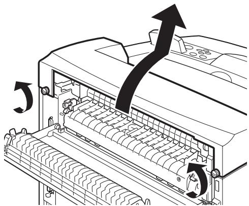
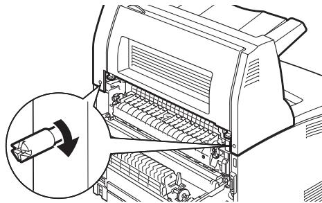
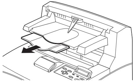
If paper jams....56
Inside Cover A 58
Inside the Paper Tray 59
Error Messages....61
Index 63
Limited Warranty:
United States and Canada....64
Oki Data Americas Service Centers 66
INTRODUCTION
WELCOME
Thank you for choosing an Oki B6200/B6300 Series printer. This is a guide to help you set up, install and operate your printer. To understand its features fully and to use the printer correctly and effectively, please read this guide before using the printer.
This guide is applicable to the B6200/B6300 Series printers in general although illustrations used are based on the B6300.
This guide assumes that you are familiar with the basics of how to operate your computer and, if required, network environment.
This User's Guide and other important user documents including the Reference Guide, are on the CD-ROM supplied with your printer.
FEATURES OVERVIEW
A brief overview of the main features of your printer is given here:
• Multiple up printing
• 2-sided printing
• Watermark printing
- Poster printing
- Booklet printing
• Transparency separation
- Favorites
• Special media printing
• Secure printing (requires the Hard Disk option)
• Proof printing (requires the Hard Disk option)
• Delayed printing (requires the Hard Disk option)
• Receiving restriction
ABOUT THIS GUIDE
CONVENTIONS
Throughout this guide, the four sides of the printer are referred to as front, rear, right and left. Standing at the front of the printer you can view the control panel and the rear of the printer is opposite the front. The right and left sides of the printer are defined as the sides to the right and left, respectively, of a person who is facing the front of the printer.
The following conventions are used throughout this guide to emphasize certain procedures or information:
NOTE
A note provides additional information to supplement the main text which may help you to use and understand the product.
CAUTION!
A caution provides additional information which, if ignored, may result in equipment malfunction or damage.
WARNING!
A warning provides additional information which, if ignored, may result in a risk of personal injury.
[ ]: Indicates items displayed on the computer and the printer control panel. Also indicates the title of printed reports/lists from the printer.
<>: Indicates items such as hard buttons and indicators on the keyboard and printer.
INSTALLATION AND RELOCATION PROCEDURE
The following sections guide you through the process of installing and setting up your printer right through to making a test print from an application. Complete the entire installation procedure to ensure a proper installation.
SAFETY PRECAUTIONS
This printer is available in either of the following power specifications: 110V and 220 – 240V. The specifications that apply to your printer depend on your configuration. To prevent fire or shock hazards, connect the power plug only to a properly rated power outlet.
HANDLING THE PRINTER
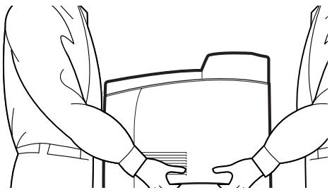
- The printer is very heavy and should always be lifted by two people. The printer with consumables weighs 20.4kg (45lb) (B6200) or 22.6kg (50lb) (B6300). Never attempt to lift the printer alone.
- To lift the printer, have two individuals facing each other from the front and rear of the printer grasp the recessed areas on each side of the printer. Do not lift the printer by grasping any area other than these recessed areas.
natural_image
Line drawing of two hands holding a rectangular object, viewed from above (no text or symbols)- When lifting the printer, maintain proper lifting posture to prevent injuries.
- Other safety information is contained in the Installation Safety or Warranty and Regulatory Information booklet supplied with this product and should be read prior to setting up the printer.
CHECKING THE PACKAGE CONTENTS
Check that all items listed below are included in the printer packaging. If any items are missing or damaged, contact your dealer.
NOTE
Retain the packaging material and box for future use if there is a possibility that the printer will be moved over long distances.
- Printer
- Drum-toner cartridge (for approximately 6,000 Letter pages at 5% coverage, i.e. 5% of the addressable print area is printed)
• 250-sheet Paper Tray
• Face Up (Rear) Tray (B6300 only)
• Power cord(s)
• Unpacking instructions and Quick Setup Guide
• Safety and Warranty Booklet - CD-ROM
The CD-ROM contains printer drivers, software and documentation designed to help you fully utilize your new printer. Oki has provided an interface, under MS Windows, to assist you in selecting the appropriate document or application.
NOTE
When the duplex unit is provided with your printer as a standard configuration, refer to “Installing the optional accessories” on page 15 to install the unit.
LOCATING PARTS OF THE PRINTER
The main parts of the printer and a brief description of their functions are shown below:
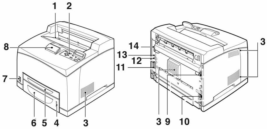
| No. | Name | Description |
| 1 | Center output tray | Print jobs are output here with printed side facing down. |
| 2 | Control panel | Consists of the control buttons, indicators and display.For control panel details, refer to “The Control Panel and Menu system” on page 43. |
| 3 | Ventilation slots | Provide ventilation for the interior of the printer. |
| 4 | Paper level indicator | Indicates the level of the remaining paper in the 550-sheet paper tray. |
| 5 | Tray 1 | Holds 150 sheets of paper. |
| 6 | Tray 2 | Holds 250 sheets (B6200) or 550 sheets (B6300) of paper. |
| 7 | Power switch | Switches the printer power on and off. |
| 8 | Extension output tray | Pull this tray out to print on paper larger than Letter. |
| 9 | Duplex unit connector | For connecting the duplex unit (option). |
| 10 | Power cord connector | For connecting the power cord. |
| 11 | Parallel connector | For connecting a parallel cable. |
| 12 | Network connector | For connecting the network cable when using the printer as a network printer. (The Network Software Kit option needs to have been installed to enable networking capability.) |
| 13 | USB connector | For connecting a USB cable. |
| 14 | Serial connector | For connecting a serial cable. |
PREPARING A LOCATION FOR THE PRINTER
Place the machine on a level and sturdy surface that can withstand the machine weight - 20.4 kg (45lb) (B6200) or 22.6 kg (50lb) (B6300). If tilted, the machine may fall over and cause injuries.
SPACE REQUIREMENTS
The printer has ventilation holes on the side and rear panels. Ensure that the printer is installed with a minimum clearance of 255mm (10in) from the rear vent to any wall, 200mm (8in) from the left vent to any wall, and 300mm (12in) from the right vent to any wall. A poorly ventilated machine can cause excessive internal heat and fire. The following diagram shows the minimum clearances required for normal operation, consumables replacement, and maintenance to ensure your machine operates at peak performance.
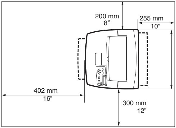
* B6200
ENVIRONMENT
Ensure that the installation location meets the following conditions:
- Do not place the printer in a hot, humid, dusty or poorly ventilated environment. Prolonged exposure to such adverse conditions can result in fire or electric shock.
- Temperature range 10 – 32 °C (50 – 89 °F), humidity range 15 – 85% (no condensation). Humidity should be 70% or below at 32 °C (89 °F), and temperature should be 28°C (82 °F) or below at 85% humidity.
NOTE
Sudden temperature fluctuations can affect print quality. Rapid heating of a cold room or moving the printer from a location with low humidity/temperature to high humidity/temperature can cause condensation inside the printer, directly interfering with image transfer. When condensation occurs, leave the printer for at least 1 hour to acclimatize to the environment before using it.
• Do not expose the printer to direct sunlight.
- Do not expose the printer to the direct draft of air-conditioning or heating.
You can install the face up (rear) tray on this printer if required.
NOTE
A face up (rear) tray can be installed on the B6300 only.
- Insert the right and left tabs of the face up (rear) tray into the holes at the back of the printer (1), and lower the tray into position (2).
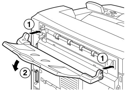
- Push up the rear output tray lever as shown in the diagram (1) and pull out the extension tray (2).
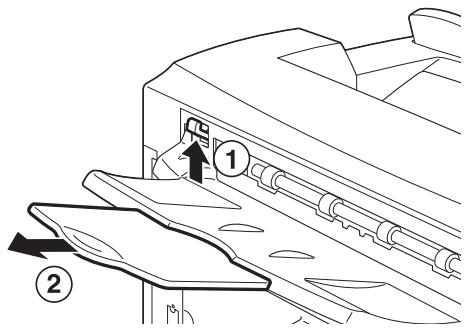
- Affix the label provided to the back of the printer.
natural_image
Line drawing of a vehicle front view with a magnified inset showing two document sheets (no text or symbols)14 > INSTALLATION AND RELOCATION PROCEDURE
INSTALLING THE OPTIONAL ACCESSORIES
If you have purchased any optional accessories, install them before setting the drum-toner cartridge and before loading paper. If there are no optional accessories to install, proceed to the next section, “Installing the Drum-Toner Cartridge” on page 35.
WARNING!
Never open or remove machine covers that are secured with screws unless specifically instructed in this guide. A high voltage component can cause electric shock.
Do not try to alter the machine configuration, or modify any parts. An unauthorized modification can cause smoke or fire.
CAUTION!
Ensure the printer is switched off before connecting any interface cables or options. Connecting cables or options to a live machine may result in an electric shock.
NOTE
To add more optional accessories when the printer is in use, you need to change the configuration of optional accessories in the printer driver. For details, refer to the Online Help for the printer driver.
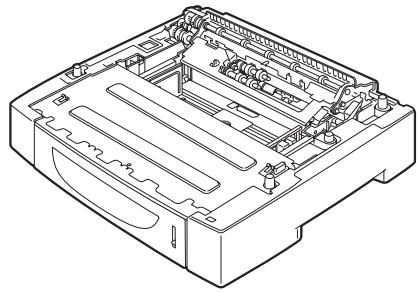
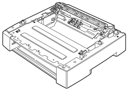
INSTALLING A UNIVERSAL TRAY
You can install up to two levels of universal tray (550-sheet) option to this printer.
This section explains how to install two trays as an example.
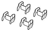
- Ensure that you have all of the following items:
• Tray module and paper tray
natural_image
Technical line drawing of a mechanical device with internal components (no text or symbols)• Fasteners (four pieces)
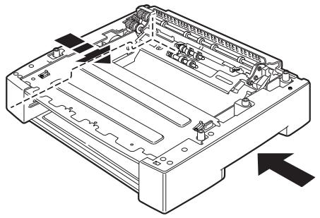
- Place the tray module to be installed at the bottom level on a flat surface, then pull out the paper tray.
natural_image
Technical line drawing of a mechanical device casing with internal compartments and mounting holes (no text or symbols)NOTE
Proceed to step 6 if you are installing only one tray module.
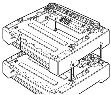
- Lift the tray module to be installed at the top level by holding the parts as shown in the diagram.
natural_image
Technical line drawing of a mechanical device with internal components and an arrow indicating direction (no text or symbols)- Align the front and back corners of the top and bottom tray modules, and slowly lower the top module so that the guide pins at the four corners of the bottom module fit into the holes at the base plate of the top module.
CAUTION!
The tray module must be lowered gently. Otherwise, the interior parts may be damaged.
natural_image
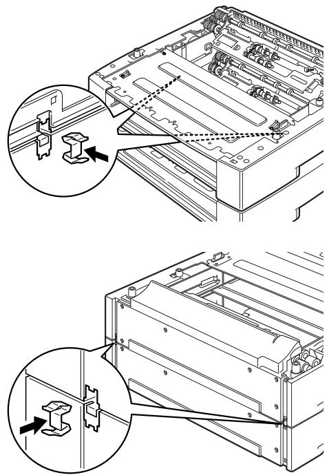
Technical line drawing of a mechanical assembly with multiple components and mounting holes (no text or symbols)- Insert the fasteners provided into the two locations inside the tray module and the two locations at the back of the tray module. Insert the fasteners securely.
natural_image
Technical line drawing of a mechanical assembly with two views showing internal components and alignment (no text or symbols)- Pull the paper trays out of the printer.
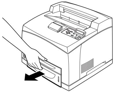
natural_image
Line drawing of a hand pressing down on a printer's front panel (no text or symbols)- Lift up the printer by holding the recessed areas.
- Align the corners of the printer and the tray modules, and lower the printer gently so that the guide pins at the four corners of the tray modules fit into the holes at the base plate of the printer.
CAUTION!
The printer must be lowered gently. Otherwise, interior parts of the tray modules may be damaged.
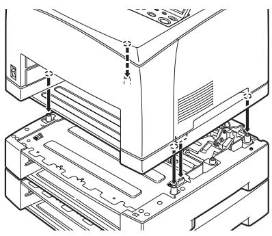
natural_image
Technical line drawing of a computer tower with visible internal components and mounting brackets (no text or labels)- Insert the fasteners provided into the two locations inside and the two locations at the back of the printer. Insert the fasteners securely.
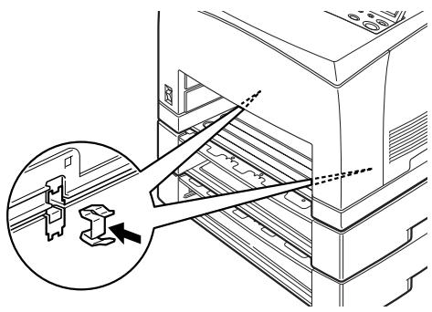
natural_image
Technical line drawing of a mechanical assembly with an inset showing a component detail (no text or symbols)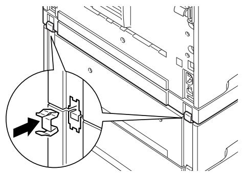
natural_image
Technical line drawing of a mechanical assembly with an inset showing a close-up of a component detail (no text or symbols)- Push both trays completely into the printer.
NOTE
For details on how to load paper, refer to “Loading paper” on page 40.
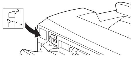
INSTALLING THE DUPLEX UNIT
You can install a duplex unit option on this printer. If a face up tray has been fitted, remove it by reversing the steps in “Installing the Face Up (Rear) Tray” on page 14 before installing the duplex unit and refit it when the duplex unit has been installed.
- Remove the duplex unit cover by pushing the two tabs as shown in the diagram (1).
Next, remove the connector cap at the top right of the back of the printer (2).
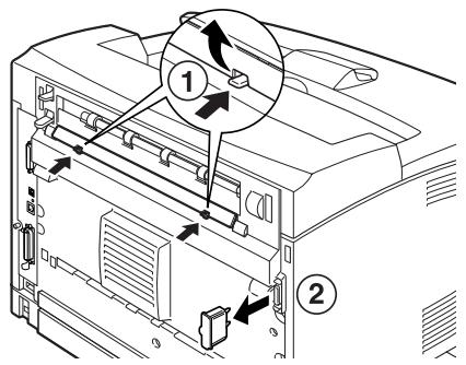
- Insert the right and left tabs at the bottom of the duplex unit into the holes at the back of the printer, and then align the top part of the duplex unit with the printer.
Ensure that the connector of the duplex unit is connected to the connector of the printer.
natural_image
Technical line drawing of a printer or printer with internal components and directional arrows indicating flow (no text or symbols)- Tighten the screws at both ends of the bottom of the duplex unit.
natural_image
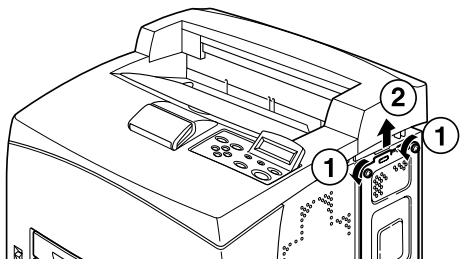
Technical line drawing of a mechanical device with a close-up inset showing a component (no text or symbols)INSTALLING THE OFFSET CATCH TRAY
You can install an offset catch tray option on this printer.
NOTE
An offset catch tray can be installed on the B6300 only.
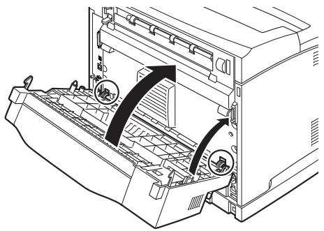
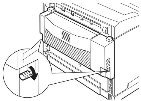
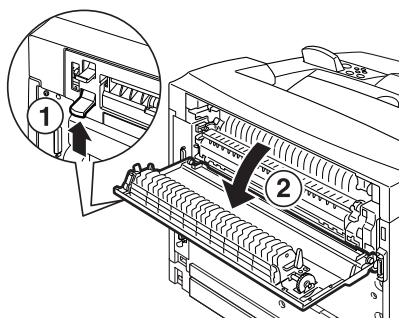
- Lift the second lever on the top left corner at the back of the printer (1), and open the cover (2).
NOTE
When the duplex unit is installed, lift the lever on top of the left side cover of the unit and open the unit, then open the cover as shown in the diagram.
- Loosen the right and left thumbscrews as shown in the diagram to uninstall the top cover of the paper exit.
natural_image
Diagram of a mechanical device with internal components and directional arrows indicating motion (no text or symbols)- Insert the right and left tabs of the offset catch tray into the holes at the top of the printer (1) and lower it slowly onto the top of the printer (2).
- Secure the screws at both ends of the bottom of the offset catch tray.
natural_image
Technical illustration of a printer with a magnified inset showing internal structure (no text or symbols)24 > INSTALLATION AND RELOCATION PROCEDURE
- Close the cover.
- If you install the face up (rear) tray on the printer, affix the label provided to the back of the offset catch tray.
natural_image
Line drawing of a computer monitor with an open lid and directional arrows indicating file orientation (no text or symbols)- Pull out the extension tray.
natural_image
Line drawing of a printer's internal structure with no text or symbolsCAUTION!
Printing while the tray is folded up may cause a paper jam. Be sure to open the tray when using the printer.
- Flip up the stopper when printing on heavy weight papers.

natural_image
Technical line drawing of a mechanical assembly with a hand operating a tool (no text or symbols present)INSTALLATION AND RELOCATION PROCEDURE > 25
INSTALLING A NETWORK SOFTWARE KIT, HARD DISK, COMPACT FLASH DISK, OR ADDITIONAL MEMORY
The same steps are required at the beginning and at the end of each installation to prepare the printer and to close it. These steps are described here.
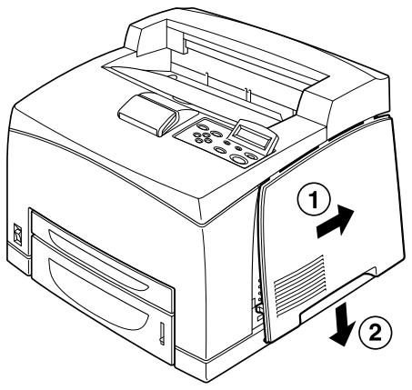
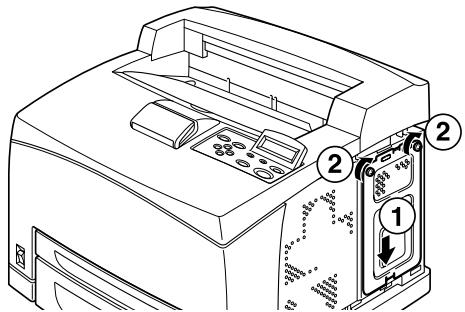
Preparing the printer
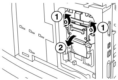
- Remove the screw on the right detachable cover.
natural_image
Technical diagram of a computer monitor with an inset showing a cable or cable device (no text or symbols present)- Slide the cover towards the back of the printer (1) to release the protrusions at the bottom and pull it downwards (2).
- Remove the two screws on top of the metal cover (1), and pull the metal cover upwards (2).
Closing the printer
- Align and insert the protrusion at the bottom of the metal cover into the notch of the printer (1), and tighten the two screws on the top of the cover (2).
- Align and insert the protrusions at the top of the right detachable cover into the notches of the printer (1). Fit the protrusions at the bottom of the cover into the printer (2) and slide the cover towards the front of the printer (3).
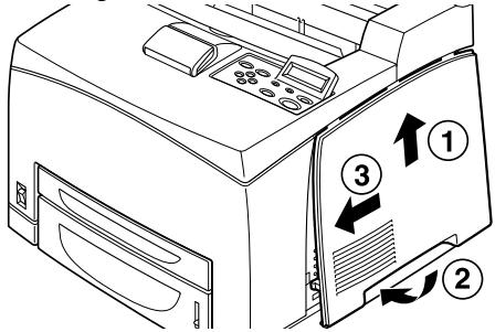
- Tighten the screw on the right detachable cover.
INSTALLING A NETWORK SOFTWARE KIT
You can install a network software kit option on this printer. Installing this option may initialize the settings of [Network/Port] and [Allocate Memory].
CAUTION!
Never touch the connectors of the network software kit.
Never allow the network software kit to be bent or damaged.
Before handling the network software kit, touch something metal in order to discharge any electrostatic charge built up in your body.
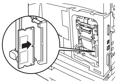
- Refer to "Preparing the printer" on page 26.
- Hold the network software kit so its notch (1) is aligned with the protrusion on the slot.
- Release the hook on the top of the slot.
natural_image
Technical line drawing of a mechanical assembly with an inset showing a component being inserted (no text or symbols present)- Gently insert the network software kit into the slot, and press firmly at the top corner of the card then at the bottom corner.
Inserting the network software kit fully and securely into the slot will cause the hook on the top of the slot to rise.
NOTE
Be sure to insert the network software kit securely into the slot as far as it will go.
natural_image
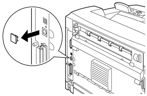
Technical line drawing of a mechanical assembly with an inset showing a close-up of a component (no text or symbols present)- Remove the cap from the network connector.
- Refer to "Closing the printer" on page 27.
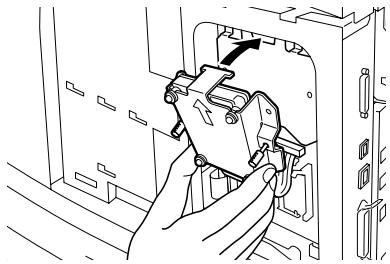
INSTALLING A HARD DISK
You can install a hard disk option on this printer.
NOTE
When the Compact Flash disk (option) is installed on your printer, you cannot install the hard disk. You can install only one of them.
Installing this option may initialize the settings of [Network/Port] and Allocate Memory].
CAUTION!
The hard disk is a delicate item and must be handled with care. In the event that damage does occur, it may erase important data saved on the disk. It is recommended that you back up your data regularly.
- Refer to "Preparing the printer" on page 26.
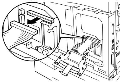
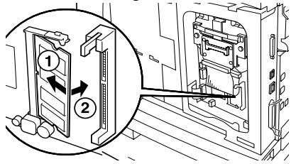
- Remove the screws on the right and left sides of the Compact Flash bracket (1) and remove the Compact Flash disk drive as shown in the diagram (2).
- Remove the cable of the Compact Flash bracket from the connector on the printer.
natural_image
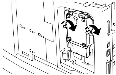
Technical line drawing of a mechanical assembly with a magnified inset showing internal components (no text or symbols)- Connect the cable of the hard disk to the connector on the printer as shown in the diagram.
CAUTION!
When connecting the cable, hold the disk firmly by hand to prevent it from dropping.

natural_image
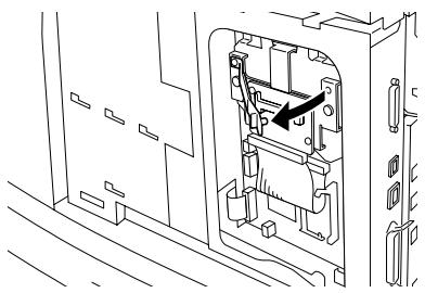
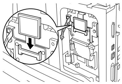
Technical line drawing of a mechanical assembly with an inset showing a component detail (no text or symbols)- Hold the hard disk as shown in the diagram, and install it in the printer. Align the arrow on the hard disk with the arrow on the printer, and insert the bracket at the top of the disk into the install position.
natural_image
Line drawing of a hand inserting a component into a device (no text or symbols visible)- Tighten the screws on both sides of the hard disk.
natural_image
Technical line drawing of a mechanical assembly with directional arrows indicating motion (no text or symbols)- Refer to "Closing the printer" on page 27.
INSTALLING A COMPACT FLASH DISK
You can install a Compact Flash disk option (only available in certain regions) to this printer.
NOTE
When the hard disk (option) is installed on your printer, you cannot install the Compact Flash disk. You can install only one of them.
Installing a Compact Flash disk erases any data that resides in the Compact Flash disk.
Installing this option may initialize all the printer settings for allocating memory.
- Refer to "Preparing the printer" on page 26.
- Open the fastener on the Compact Flash disk drive.
natural_image
Technical line drawing of an electrical enclosure with internal components (no text or symbols)- Locate the Compact Flash disk as shown in the diagram.
natural_image
Diagram showing a computer monitor mounted on an electronic device with a magnified inset highlighting the screen (no text or symbols present)- Close the fastener.
natural_image
Technical line drawing of a mechanical assembly with internal components (no text or symbols)- Refer to "Closing the printer" on page 27.
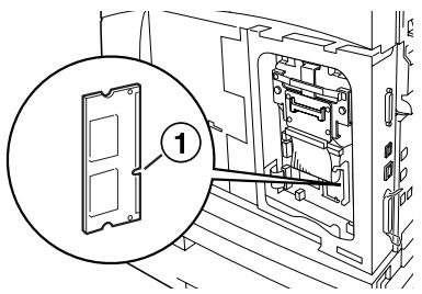
INSTALLING ADDITIONAL MEMORY
The additional memory module for this printer is 512MB.
CAUTION!
Do not touch the terminal area of the additional memory.
Do not bend or damage the additional memory.
Before handling the memory board, touch something metal in order to discharge any electrostatic charge built up in your body.
To add more memory when the printer is in use, you need to configure the memory capacity in the printer driver. For details, refer to the Online Help for the printer driver.
- Refer to “Preparing the printer” on page 26.
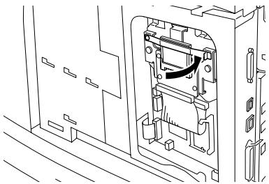
- Hold the additional memory so that the notch (1) is aligned with the protrusion on the slot.
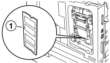
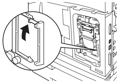
- Insert the additional memory at an angle (1) and push it into the printer until it clicks into position (2).
NOTE
Ensure that the additional memory is firmly inserted.
- Refer to "Closing the printer" on page 27.
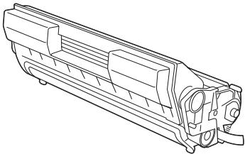
INSTALLING THE DRUM-TONER CARTRIDGE
natural_image
Technical line drawing of a mechanical component or housing (no text or symbols visible)NOTE
Your printer is supplied with a drum-toner cartridge with capacity 6,000 Letter pages at 5% coverage. Replacement drum-toner cartridges are available with capacity 10,000 pages (B6200/B6300) or 17,000 pages (B6300 only).
When handling the drum-toner cartridge, take note of the following points:
WARNING!
Never throw a drum-toner cartridge into an open flame as it can cause an explosion.
- Do not subject the drum-toner cartridge to direct sunlight or strong light.
- When installing the drum-toner cartridge, select a location not subject to strong light and try to finish the installation within 5 minutes.
- Do not touch the surface of the photosensitive drum. Do not let the drum-toner cartridge stand upside down or place it upside down as this may damage the drum.
- A drum shutter protects the photosensitive drum from light. Do not open the drum shutter.
-
Although the toner is not harmful to the body, wash it off immediately with cold water if your hands or clothes are in contact with it.
-
It is recommended to use up the drum-toner cartridge within one year of removing it from its packaging.
-
Keep the drum-toner cartridge out of the reach of children.
-
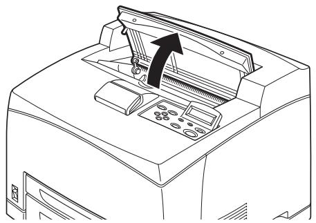
Open the cover.
natural_image
Line drawing of a printer front panel with an arrow indicating the paper's edge (no text or symbols present)NOTE
When the optional offset catch tray is installed, fold the tray first before opening the cover.
WARNING!
Do not touch any parts inside the printer.
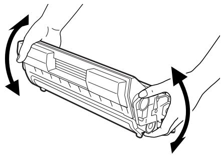
- Take the drum-toner cartridge out of the packaging box and shake it seven or eight times as shown in the diagram.
natural_image
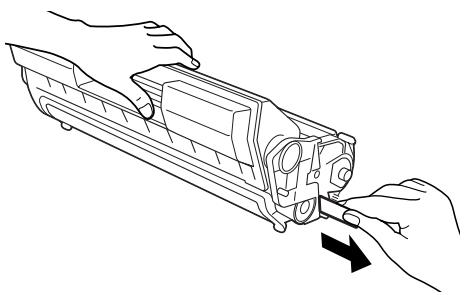
Diagram of hands holding a cylindrical device with rotating arrows indicating rotation (no text or symbols)- Place the drum-toner cartridge on a flat surface and pull out the seal horizontally.
natural_image
Line drawing of a mechanical component being inserted into a housing, with arrows indicating direction (no text or symbols)CAUTION!
When pulling out the seal, pull it out horizontally. The tape might break if it is pulled out diagonally.
After the seal has been pulled out, do not shake or bump the drum-toner cartridge.
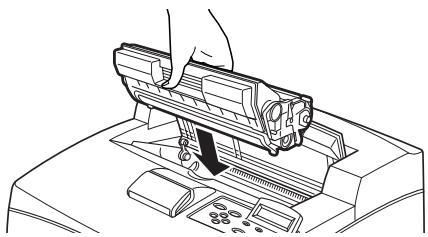
- Hold the drum-toner cartridge by the grip and insert it into the slot inside the printer.
natural_image
Line drawing of a hand operating a firearm on a device (no text or symbols)CAUTION!
Do not touch any parts inside the printer.
Ensure that the drum-toner cartridge is firmly located.
- Close the cover securely.
NOTE
If the offset catch tray is folded as in Step 1, close the cover and then return the tray to its original position.
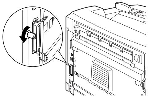
CONNECTING AN INTERFACE CABLE
Connect the interface cable to be used to the printer.
NOTE
Connect a USB cable only after the printer driver has been installed on the computer.
- Connect the interface cable to the interface connector at the back of the printer: serial (1), USB (2), network (3), parallel (4). For a parallel cable, lift up the wire clip on both sides to secure it after it has been inserted into the connector.
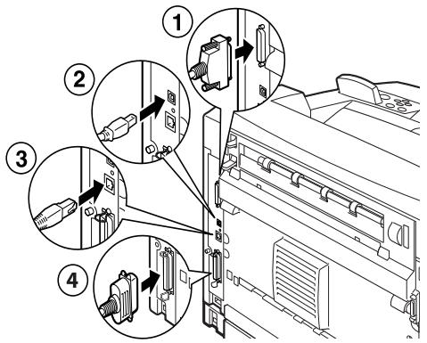
- For Parallel, USB, or Serial cables, connect the other end of the cable to the interface connector of the computer.
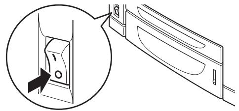
When connecting the power cord, take heed of the information given in “Safety precautions” on page 9.
- Ensure that the printer power switch is in the O position.
natural_image
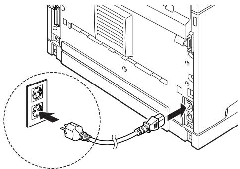
Diagram showing a door handle mechanism with an arrow pointing to the lock (no text or symbols present)- Connect the power cord to the power cord connector at the back of the printer. Connect the other end of the power cord to the power outlet.
natural_image
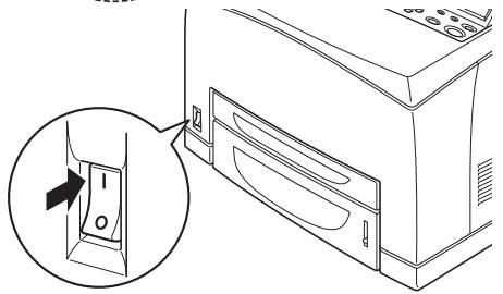
Diagram of a server rack with connected power plugs and a socket, showing no text or symbols- Press the power switch of the printer to the <|> position. The power will be applied and the control panel will display that the printer is ready to print.
natural_image
Line drawing of a microwave oven with an inset showing a close-up of the door handle (no text or symbols)NOTE
If "Found New Hardware" displays on your screen, click Cancel.
Depending on the network environment used, it may take some minutes before the printer is ready for printing.
If the message that the printer is ready to print but is unable to retrieve an IP Address is displayed, continue operating as normal.
LOADING PAPER
This section explains how to load Letter size plain paper in portrait orientation in the paper tray.
Portrait orientation

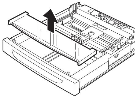
- Place the paper tray on a flat surface and remove the lid.
natural_image
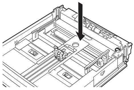
Technical line drawing of a mechanical device with an arrow indicating a component (no text or symbols present)- If the base plate of the paper tray is raised, push it down.
natural_image
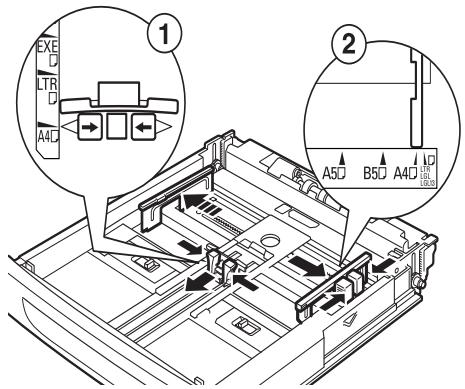
Technical line drawing of a mechanical assembly with a black arrow pointing to a component (no text or symbols present)- Squeeze the length guide and slide it to the desired paper size (1). Squeeze the right width guide and slide it to the desired paper size (2).
- Load the paper with the side to be printed facing up and with all four corners aligned.
natural_image
Isometric line drawing of a rectangular electronic device with a black arrow pointing to the top panel (no text or symbols)CAUTION!
Do not place paper over the right width guide.
Do not load paper exceeding the maximum fill line or the maximum capacity allowed.
Align the right width guide with the paper width correctly. If the right width guide is not in place, the paper will not be properly fed and this may cause paper jams.
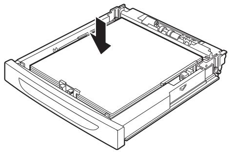
- Close the lid of the paper tray and push the tray completely into the printer.
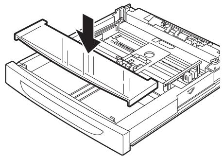
natural_image
Technical line drawing of a mechanical assembly with a downward arrow indicating a component (no text or symbols present)CAUTION!
The lid of the tray must be firmly closed. If not, the paper may become misaligned.
- Depending on the types and sizes of the loaded paper, you need to configure settings on the control panel.
Change the paper type when non-plain paper such as recycled paper, heavyweight paper or transparencies is loaded.
Configure the paper size when custom size paper is loaded.
THE CONTROL PANEL AND MENU SYSTEM
For full details on the control panel and menu structure, refer to the Reference Guide.
The control panel components and their functions are described below:
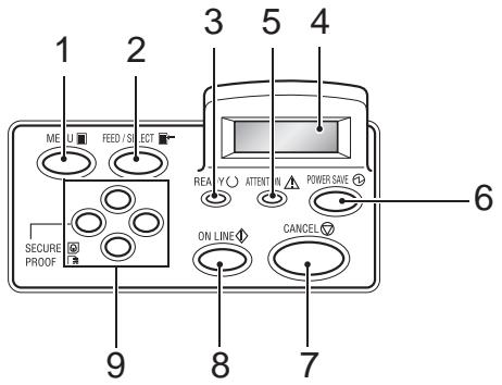
| No. | Name | Description |
| 1 | Press to display/close the menu screen. | |
| 2 | Press to set the required menu value and use to print reports/lists. | |
| 3 | When illuminated, the printer is ready to receive data from the computer. | |
| 4 | LCD Display | Displays menu values, printer status and error messages. |
| 5 | When illuminated, there is a malfunction in the printer. | |
| 6 | Press to enter/exit power save mode. The indicator is illuminated when the printer is in power save mode. | |
| 7 | Press to cancel printing. | |
| 8 | Press to enter offline status, in which the printer cannot receive data or process printing data. Press again to exit offline status and enter online status, in which the printer can receive data from the computer. | |
| 9 | <▲><▼><◀><▶>buttons | Press these to move to the required menu, item and required value on the display. Also, press the <◀> button when you are carrying out secure/sampled/delayed printing or when you are checking/printing received mail manually.Note: When you are changing the candidate values by the <▲><▼> buttons, you can press and hold down the buttons to change the display continuously. Also, pressing the <▲><▼> buttons simultaneously displays the default values. |
NAVIGATING THE CONTROL PANEL MENUS
| Display/Close the Menu screen | button |
| Switch between the menu levels | button (moves one level downwards) orbutton (moves one level upwards) |
| Switch between menus or items in the same level | button (displays the previous menu or item) orbutton (displays the next menu or item) |
| Move the cursor(_) of the setting value to the right or left | button (moves to the right) orbutton (moves to the left) |
| Confirm setting | button |
When you press the MENU button on the control panel, you enter the printer's menu system. At that point, the first line of the display contains the text [Menu], indicating that you are in the menu system. The second line of the display lists the active menu, which you can change by pressing the <▲> or <▼> button.
Using these buttons repeatedly, you can cycle through the main menus in the following order: Print Language; Report/List; Meter Reading; Admin Menu; Display Language.
By using the arrow buttons as indicated above, you can navigate through the menu system to make any required settings. For example, to set the paper type in Tray 1 to accommodate recycled paper, navigate as follows: Admin Menu, Printer Settings, Paper Type, Tray 1, Recycled then press the
SELECTING THE CONTROL PANEL LANGUAGE
English is the default language for all error and status messages; however, these messages are also available in many languages. Use the following procedure to change the display language.
NOTE
Refer to the section “The Control Panel and Menu system” on page 43 for a brief overview of the control panel and its menus and sub-menus.
- Press the
- Press the <▲> or <▼> button until [Display Language] is displayed, then press the <▶> button.
- Press the <▲> or <▼> button until the required language is displayed, then press the
button. - Press the
PRINTING A CONFIGURATION SUMMARY
To check whether the printer is correctly installed, use the control panel to print the [System Settings List].
NOTE
If you have made a mistake when operating the control panel, press the