
GZ7936XHS - INSTALLATION INSTRUCTION - Built-in oven BAUKNECHT - Free user manual and instructions
Find the device manual for free GZ7936XHS - INSTALLATION INSTRUCTION BAUKNECHT in PDF.

| Brand | BAUKNECHT |
| Model | GZ7936XHS |
| Product type | Retractable downdraft ventilation system for cooktop |
| Width | 91.4 cm (36 in) |
| Power supply | 120 V, 60 Hz, AC, 15 A, dedicated circuit |
| Maximum airflow (with external motor KPEC992M) | 900 cfm (25.5 m³/min) |
| Ventilation type | Downdraft, retractable |
| Controls | Top button (on/off) + side rotary knob (continuous variable speed) |
| Material | Stainless steel (estimate) |
| Number of filters | 2 washable metal filters |
| Filter maintenance | Dishwasher or hot detergent cleaning |
| Surface cleaning | Water and soap; do not use abrasive products |
| Safety | Microswitch prevents operation without filters; shutdown in case of liquid spill |
| Installation type | Flush-mounted in countertop, behind cooktop |
| Venting | Rigid metal duct (diam. 15.2 cm (6 in) or 25.4 cm (10 in) depending on motor) to outside |
| Maximum duct length | 8.9 m (35 ft) for 15.2 cm diameter; 16.8 m (55 ft) for 25.4 cm diameter |
| Warranty | 1 year limited (parts and labor) |
| Supplied accessories | Top trim, end caps, support feet, support and mounting brackets, screw bag, adjustment damper, metal cover |
| Weight | Not specified (estimate 20-30 kg) |
| Intended use | General ventilation to remove smoke, steam, and cooking odors |
Frequently Asked Questions - GZ7936XHS - INSTALLATION INSTRUCTION BAUKNECHT
User questions about GZ7936XHS - INSTALLATION INSTRUCTION BAUKNECHT
0 question about this device. Answer the ones you know or ask your own.
Ask a new question about this device
Download the instructions for your Built-in oven in PDF format for free! Find your manual GZ7936XHS - INSTALLATION INSTRUCTION - BAUKNECHT and take your electronic device back in hand. On this page are published all the documents necessary for the use of your device. GZ7936XHS - INSTALLATION INSTRUCTION by BAUKNECHT.
USER MANUAL GZ7936XHS - INSTALLATION INSTRUCTION BAUKNECHT
Installation Instructions and Use and Care Guide
30'' (76.2 ~cm)
36'' (91.4 ~cm)
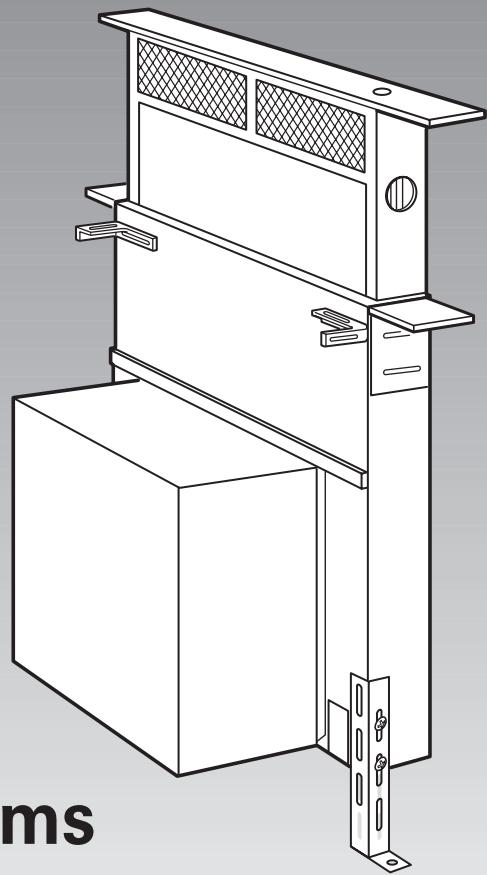
Retractable (Pop-up)
Downdraft Vent Systems
IMPORTANT:
Read and save
these instructions.
IMPORTANT:
Installer: Leave Installation Instructions with the homeowner.
Homeowner: Keep Installation Instructions for future reference.
Save Installation Instructions for local electrical inspector's use.
Quick Reference
Table of Contents:
Pages

Before you start

Electrical requirements

Product dimensions

Cabinet dimensions

Countertop cutout dimensions

Vent system requirements
Interior-mounted vent motor

Installation steps

Vent system requirements
Exterior-mounted vent motor

Installation steps

Use and Care Information

Accessories
Before you start...
Your safety and the safety of others are very important.
We have provided many important safety messages in this manual and on your appliance. Always read and obey all safety messages.

This is the safety alert symbol.
This symbol alerts you to fatal hazards that can kill or injure and others.
All safety messages will follow the safety alert symbol and either the word "DANGER" or "WARNING". These words mean:
DANGER
You can be killed or seriously injured if you don't immediately follow instructions.
WARNING
You can be killed or seriously injured if you don't follow instructions.
All safety messages will tell you what the potential hazard is, tell you how to reduce the chance of injury, and tell you what can happen if the instructions are not followed.
IMPORTANT: Observe all governing codes and ordinances.
Failure to meet codes and ordinances could lead to fire or electrical shock.
Proper installation is your responsibility. Make sure you have everything necessary for correct installation. It is the responsibility of the installer to comply with the installation clearances specified on the model/serial rating plate. The model/serial rating plate is located on the front of the downdraft vent above the wiring box cover.
Check location where downdraft vent will be installed. The location should be away from strong draft areas, such as windows, doors and strong heating vents or fans. Before making countertop cutout, check that downdraft vent and cooktop location will clear cabinet walls, backsplash, and rear wall studs inside cabinet.
Mobile home installation
The installation of this downdraft vent system must conform to the Manufactured Home Construction Safety Standards, Title 24 CFR, Part 328 (formerly the Federal Standard for Mobile Home Construction and Safety, Title 24, HUD, Part 280) or when such standard is not applicable, the Standard for Manufactured Home Installation 1982 (Manufactured Home Sites, Communities and Setups) ANSI A225.1/NFPA 501A*, or latest edition, or with local codes.
All openings in the wall or floor where retractable downdraft vent is to be installed must be sealed.
Electrical ground is required. See "Electrical requirements," page 3.
When installing downdraft vent, the cabinet drawer will need to be removed and the drawer front installed permanently to cabinet.
NOTE: Downdraft vent is installed directly behind the cooktop. Install downdraft vent first.
Cabinet construction: Downdraft vent is designed for use in a cabinet with a depth of 24" (61 cm). Some installations require a countertop deeper than 25" (63.5 cm). See chart on page 5. The maximum depth of the overhead cabinet is 13" (33 cm). Overhead cabinets installed at either side of the downdraft vent must be 18" (45.7 cm) above the cooking surface.
See cooktop Installation Instructions before making any cutouts and for the minimum distance between the front edge of the countertop and front edge of cooktop. The minimum horizontal distance between the overhead cabinets is the same as the width of the installed downdraft vent.
When installing a 36" (91.4 cm) retractable downdraft vent with "Create-A-Cooktop" modules, the optional support must be installed on the front of the downdraft vent. See installation steps for details.
Parts supplied for installation:
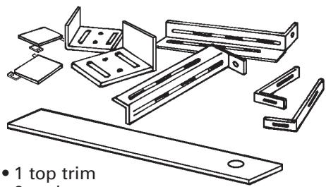
- 1 top trim
- 2 end caps
2 lower support legs - 2 overcounter support brackets
- 2 undercounter mounting brackets
- 1 bag of fasteners
1 metal cover - 1 backdraft damper
- literature package
- optional support and two screws (36" (91.4 cm) models only
Parts needed for installation:
- 2 U.L.- or C.S.A.-listed 1 / 2'' (12.7 mm) conduit connectors (3 are required if the exterior-mounted vent motor is used.)
- 1 wall cap for interior-mounted motor
- vent system
- power supply cable
- wiring cable for optional remote blower kit.
Tools needed for installation:
- safety glasses
gloves - jig or keyhole saw
- drill with 1/8'' drill bit
- pencil
- measuring tape
- flat-blade screwdriver
- Phillips screwdriver
- 3/8'' (9.5 mm) nut driver or ratchet
level - pliers
metal snips - wire stripper or utility knife
- caulking gun and weatherproof caulk
- duct tape
IMPORTANT: Observe all governing codes and ordinances.
It is the customer's responsibility:
- To contact a qualified electrical installer.
- To assure that the electrical installation is adequate and in conformance with National Electrical Code, ANSI/NFPA 70 - latest edition, or CSA Standards C22.1-94, Canadian Electrical Code, Part 1 and C22.2 No. 0-M91 - latest edition* and all local codes and ordinances.
If codes permit and a separate ground wire is used, it is recommended that a qualified electrician determine that the ground path is adequate.
Do not ground to a gas pipe.
Check with a qualified electrician if you are not sure downdraft vent is properly grounded.
Do not have a fuse in the neutral or ground circuit.
IMPORTANT: Save Installation instructions for electrical inspector's use.
A. A 120-volt, 60-Hz, AC-only, fused electrical supply is required on a separate 15 amp circuit. A time-delay fuse or circuit breaker is recommended. The fuse must be sized per local codes in accordance with the electrical rating of the downdraft vent as specified on the model/serial rating plate located on the front of the downdraft vent above the wiring box cover.
B. The downdraft vent must be connected with copper wire only.
C. Wire sizes and connections must conform to the requirements of the National Electrical Code, ANSI/NFPA 70 - latest edition, or CSA Standards C22.1-94, Canadian Electrical Code, Part 1 and C22.2 No. 0-M91 - latest edition* and all local codes and ordinances.
WARNING — TO REDUCE THE RISK OF FIRE, ELECTRIC SHOCK, OR INJURY TO PERSONS, OBSERVE THE FOLLOWING:
Installation work and electrical wiring must be done by qualified person(s) in accordance with all applicable Codes and Standards, including fire related construction. Sufficient air is needed for proper combustion and exhausting of gases through the flue (chimney) of fuel burning equipment to prevent back drafting. Follow the heating equipment manufacturer's guideline and safety standards such as those published by the National Fire Protection Association (NFPA), and the American Society of Heating Refrigeration and Air Conditioning Engineers (ASHRAE), and the local code authorities.
When cutting or drilling into wall or ceiling, do not damage electrical wiring and other hidden utilities.
Ducted fans must always be vented to the outdoors.
WARNING — To reduce the risk of fire, use only metal ductwork.
This unit must be grounded.
D. This downdraft vent should be connected directly to the fused disconnect (or circuit breaker) through flexible, armored or nonmetallic sheathed, copper cable. Allow some slack in the cable so the downdraft vent can be moved if servicing is ever necessary.
E. A U.L.- or C.S.A.-listed, 1 / 2^ (12.7 mm) conduit connector must be provided at each end of the power supply cable (at the downdraft vent and at the junction box).
A wiring diagram is located on the downdraft vent base above the wiring box cover.
Copies of the standards listed may be obtained from:
- National Fire Protection Association One Batterymarch Park Quincy, Massachusetts 02269
**CSA International
8501 East Pleasant Valley Road
Cleveland, Ohio 44131-5575
Product dimensions
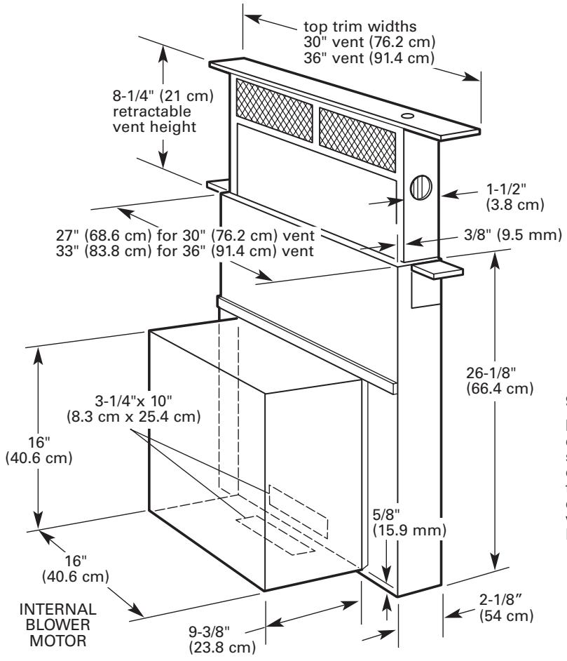
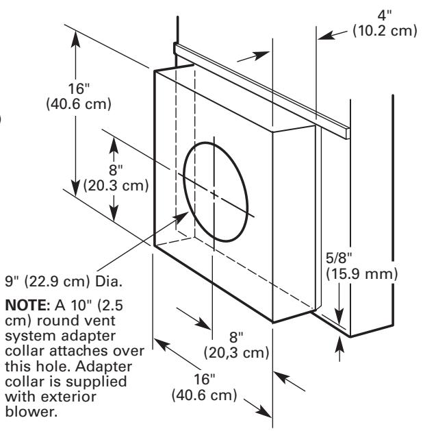
EXTERIOR-MOUNTED BLOWER MOTOR
Cabinet dimensions
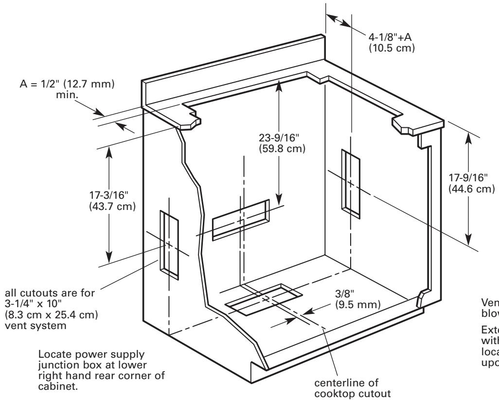
See cooktop manufacturer's instructions for cooktop cutout depth and width.
Use dimensions for vent system cutout location that applies to your installation.
Vent system cutout dimensions for internal blower models only.
Exterior mounted blower systems connect with 10^ (25.4 cm) round vent. The cutout locations for this vent system will depend upon your specific installation.
Countertop cutout dimensions
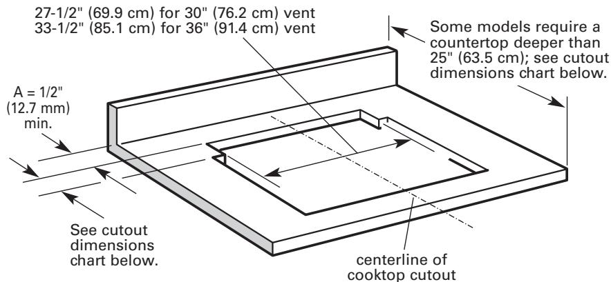
It is recommended that the cooktop and vent cutouts be drawn on the countertop before making any cutouts to avoid mistakes.
See Cooktop Installation Instructions for complete cutout dimensions, location dimensions and installation details.
IMPORTANT: Countertops with a bullnosed front edge are not recommended for these installations. Use only the exterior-mounted blower system, KPEC992M [900 cfm (25.5 m³/m)], with the retractable popup downdraft vent system.
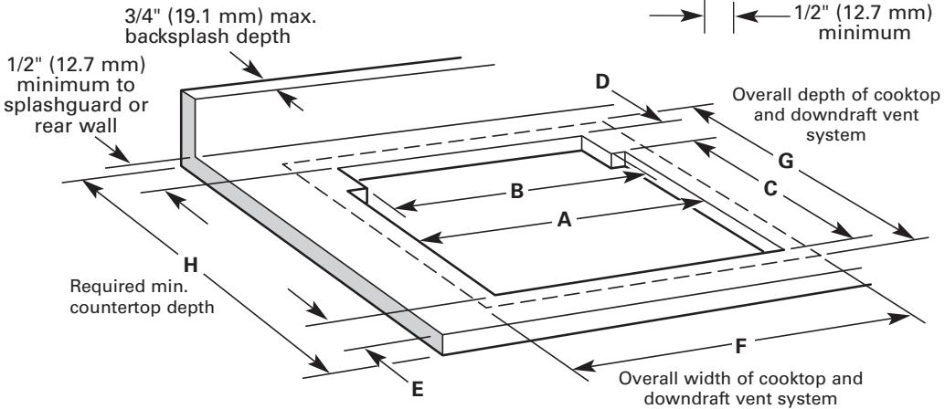
| Cooktop Models | Cooktop Size | Installed with Vent System Models | A | B | C | D | E | F | G | H | ||
| KGCS105G | 30" (76.2 cm) | KIRD801HSS | KIRD802HSS | 29" (73.7 cm) | 27-1/2" (69.9 cm) | 19-5/8" (49.8 cm) | 2-1/8" (5.4 cm) | 1-3/4" (4.4 cm) | 31-3/8" (79.7 cm) | 23" (58.4 cm) | 25" (63.5 cm) | |
| KECC502G* KECC507G* KECC507K* KECC508G* | 30" (76.2 cm) | KIRD801HSS | KIRD802HSS | 29-1/2" (74.9 cm) | 27-1/2" (69.9 cm) | 20-1/2" (52.1 cm) | 2-1/8" (5.4 cm) | 2" (5.1 cm) | 31-1/2" (80.0 cm) | 23-1/4" (59.1 cm) | 25-7/8" (65.7 cm) | |
| KECS100G* | 30" (76.2 cm) | KIRD801HSS | KIRD802HSS | 28-7/8" (73.3 cm) | 27-1/2" (69.9 cm) | 19" (48.3 cm) | 2-1/2" (6.4 cm) | 3-3/8" (8.6 cm) | 31-1/2" (80.0 cm) | 23" (58.4 cm) | 25-5/8" (65.1 cm) | |
| GLT3014G SCS3004G SCS3004L SCS3014G SCS3014L | 30" (76.2 cm) | GZ7730XGS GZ7930XHS | 29" (73.7 cm) | 27-1/2" (69.9 cm) | 19-5/8" (49.8 cm) | 2-1/8" (5.4 cm) | 1-3/4" (4.4 cm) | 31-3/8" (79.7 cm) | 23" (58.4 cm) | 25" (65.1 cm) | ||
| RCC3024G* GJC3034G* RCS3014L* RCS3014L* YRCS3014L* | 30" (76.2 cm) | GZ7730XGS GZ7930XHS | GZ7930XGS | 29-1/2" (74.9 cm) | 27-1/2" (69.9 cm) | 20-1/2" (52.1 cm) | 2" (5.1 cm) | 2" (5.1 cm) | 30" (76.2 cm) | 23" (58.4 cm) | 25-3/4" (65.4 cm) | |
| 30" (76.2 cm) | GZ7730XGS GZ7930XHS | GZ7930XGS | 28-7/8" (73.3 cm) | 27-1/2" (69.9 cm) | 19" (48.3 cm) | 2-1/2" (6.4 cm) | 3" (7.6 cm) | 31-1/2" (80.0 cm) | 23" (58.4 cm) | 25-1/2" (64.8 cm) | ||
| KGCS166G | 36" (91.4 cm) | KIRD861HSS | KIRD862HSS | 35-1/4" (89.5 cm) | 33-1/2 (85.9 cm) | 19-5/8" (49.8 cm) | 2-1/8" (5.4 cm) | 1-3/4" (4.4 cm) | 37-1/2" (95.3 cm) | 23" (58.4 cm) | 25" (63.5 cm) |
| KECC562G* KECC567G* KECC568G* | 36" (91.4 cm) | KIRD861HSS | KIRD862HSS | 35-1/2" (90.2 cm) | 33-1/2" (85.9 cm) | 20-1/2" (52.1 cm) | 2-1/8" (5.4 cm) | 2" (5.1 cm) | 37-1/2" (95.3 cm) | 23-1/4" (59.1 cm) | 26-7/8" (68.3 cm) |
| KECS161G* | 36" (91.4 cm) | KIRD861HSS | KIRD862HSS | 35" (88.9 cm) | 33-1/2" (85.9 cm) | 19" (48.3 cm) | 2-1/2" (6.4 cm) | 3-3/8" (8.6 cm) | 37-5/8" (95.6 cm) | 23" (58.4 cm) | 25-5/8" (65.1 cm) |
| GLT3614XG | 36" (91.4 cm) | GZ7736XGS | GZ7936XGS | 35-1/4" (89.5 cm) | 33-1/2" (85.9 cm) | 19-5/8" (49.8 cm) | 2-1/8" (5.4 cm) | 1-3/4" (4.4 cm) | 36-5/8" (93.0 cm) | 23" (58.4 cm) | 25" (63.5 cm) |
| GLT3634XL | 36" (91.4 cm) | GZ7736XGS | GZ7936XGS | 35-1/2" (90.2 cm) | 33-1/2" (85.9 cm) | 20-1/2" (52.1 cm) | 2" (5.1 cm) | 2" (5.1 cm) | 36" (91.4 cm) | 23" (58.4 cm) | 25-3/4" (65.4 cm) |
| GJC3634G* | 36" (91.4 cm) | GZ7736XGS | GZ7936XGS | 35-1/2" (90.2 cm) | 33-1/2" (85.9 cm) | 20-1/2" (52.1 cm) | 2" (5.1 cm) | 2" (5.1 cm) | 36" (91,4 cm) | 23" (58.4 cm) | 25-3/4" (65.4 cm) |
| GJC3634L* | GZ7936XHS | ||||||||||
| RCS3614G* | 36" (91.4 cm) | GZ7736XGS | GZ7936XGS | 35" (88.9 cm) | 33-1/2" (85.9 cm) | 19" (48.3 cm) | 2-1/2" (6.4 cm) | 3" (7.6 cm) | 37-5/8" (95.6 cm) | 23" (58.4 cm) | 25-5/8" (65.1 cm) |
| RCS3614L* | GZ7936XHS |
- Installation with vent system requires countertop and base cabinet deeper than standard 25" (63.5 cm) deep countertop and 24" (61.0 cm) deep base cabinet.
Vent system requirements
Venting system must terminate to the outside.
Do not terminate the vent system in an attic or other enclosed area.
Do not use 4'' (10.2 cm) laundry-type wall caps
Do not use plastic or metal foil vent.
Vent work needed for installation is not supplied.
Wall cap is not provided with interior-mounted motor.
Determine which venting method to use. Vent system can extend through either the wall or roof.
The length of vent system and number of elbows should be kept to a minimum to provide efficient performance.
The size of the vent should be uniform.
Do not install two elbows together.
Use duct tape to seal all joints in the vent system.
Use caulking tape to seal the exterior wall or floor opening around cap.
Do not cut joist or stud. If vent cutout falls over a joist or stud, a supporting frame must be constructed.
Flexible metal vent is not recommended. If it is used, calculate each foot of flexible vent as two feet of rigid metal vent. Flexible elbows count twice as much as standard elbows.
NOTE: Make sure there is proper clearance within the wall or floor before making exhaust vent cutouts.
Recommended vent system length: For either interior-mounted or exterior-mounted blower installations, vent system length should not exceed the maximum lengths listed in the "Maximum length of vent system" chart. (See this page for Interior-mounted vent motor; page 9 for exterior-mounted vent motor.)
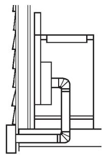
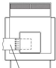
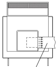
Interior-mounted vent motor
Installation requirements
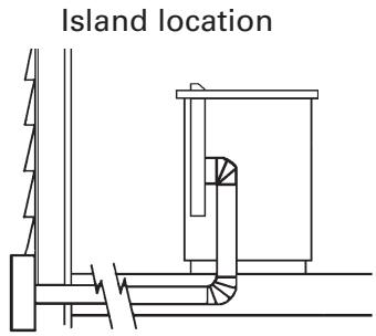
Island location

Built-in cabinet locations
rear vent
left vent
right vent
Vent system installed under a concrete slab using PVC sewer pipe.
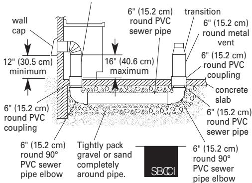
6'' (15.2 cm) round metal vent
Optional vent system installed under a concrete slab into a window well.
Do not vent a gas cooktop into a window well.
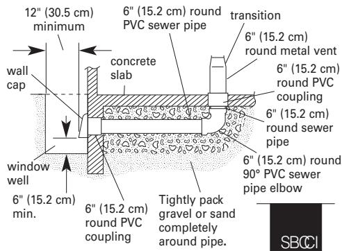
Seal the space between the outside of wall cap inlet inside of PVC coupling with caulking metal.
Maximum length of vent system
| Vent | Length |
| 6" (15.2 cm) round | 35 feet (8.9 m) |
| 3-1/4" × 10" (8.3 cm × 25.4 cm) | 35 feet (8.9 m) |
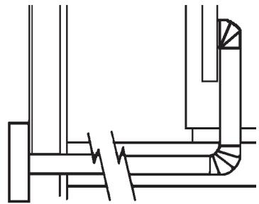
For best performance, use no more than three 90^ elbows. If more than one elbow is used, make sure that there is a minimum of 24^ (61 cm) of straight vent between any two elbows. Do not install two elbows together. It is recommended that you use round vent instead of rectangular vent, especially if elbows are required. If rectangular vent is required, it should be transitioned to 6^ (15.2 cm) round vent as soon as possible.
Determining the length of system you need:
To calculate the length of system you need, add the equivalent feet for each vent piece that will be needed. See example for 6" (15.2 cm) round vent system.
6'' (15.2 cm) round vent system
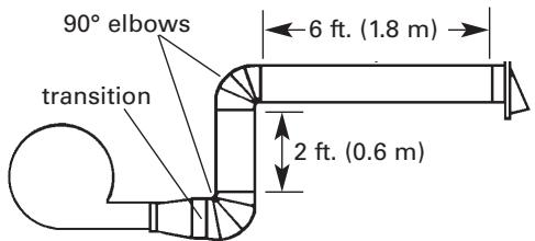
Maximum length = 35 ft. (8.9m)
1-wall cap = 0 ft. (0m)
8 ft. (2.4 m) straight = 8 ft. (2.4 m)
2-90°elbows = 10 ft. (3m)
Transition = 4.5 ft. (1.4 m)
Length of 6"
(15.2 cm) system = 22.5 ft. (6.8 m)
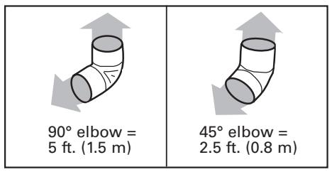
Recommended standard fittings
| 3-1/4" x 10" (8.3 cm x 25.4 cm) to 6" (15.2 cm) = 4.5 ft. (1.4 m) | 6" (15.2 cm) to 3-1/4" x 10" (8.3 cm x 25.4 cm) = 1 ft. (0.3 m) | ||
| 3-1/4" x 10" (8.3 cm x 25.4 cm) to 6" (15.2 cm) 90° elbow = 5 ft. (1.5 m) | 6" (15.2 cm) to 3-1/4" x 10" (8.3 cm x 25.4 cm) 90° elbow = 5 ft. (1.5 m) | ||
| 90° elbow = 5 ft. (1.5 m) | 45° elbow = 2.3 ft. (0.8 m) | 6" wall cap = 0 ft. (0 m) | |
Installation steps
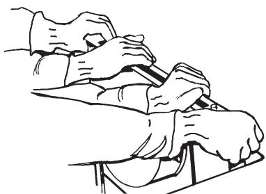
WARNING
Excessive Weight Hazard Use two or more people to move and install downdraft vent.
Failure to do so can result in back or other injury.
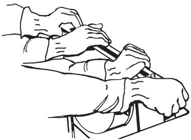
- Put on gloves and safety glasses. Place cardboard or another form of protection on top of a flat surface where you can
easily assemble the downdraft vent system. Remove parts packages, downdraft vent and blower box from carton and set on protective surface. Remove all shipping materials, tape and protective film from downdraft vent and blower box.
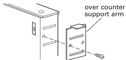
- Attach the left side and right side overcounter support brackets to the downdraft. Use 1 screw with each bracket.
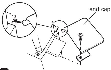
- Attach the left side and right side end caps to the downdraft. Use 1 screw with each end cap.
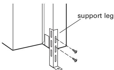
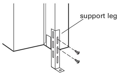
- Attach support legs to side of downdraft vent with 2 screws in each leg. Do not tighten screws.
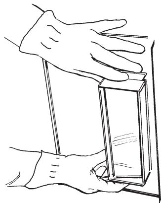
- Carefully insert downdraft vent into countertop cutout. Two people are recommended to support the weight of the downdraft vent during lifting. Check that downdraft vent is parallel to side of cutout and that mounting brackets overlap countertop.

-
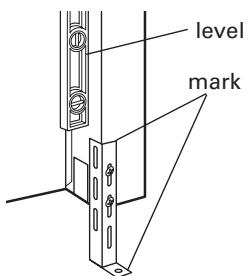
Move support legs down against cabinet floor. Place a level against front of downdraft vent base and adjust until downdraft vent is level vertically. Use a pencil to mark the top of each leg on downdraft vent. Then mark location of support leg mounting holes on cabinet floor. Remove downdraft vent from cutout. Drill starter holes at each mounting screw location on cabinet floor. Align top of legs with pencil marks on the face of the downdraft vent. Tighten screws in legs.
-
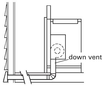
Determine which direction (down, rear, left, or right) vent will need to run from blower vent when installed in cabinet.
Down venting:
Downdraft vent is shipped with blower in down venting position so no modification is required. Go to Step 8.
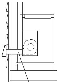
Left or right venting:
a. Remove 4 hex nuts that attach blower box to downdraft vent base. Remove blower box.
b. Rotate blower box 90^ to left or right so that vent blower is repositioned in the direction needed.
c. Reattach blower box to downdraft vent base with 4 hex nuts.
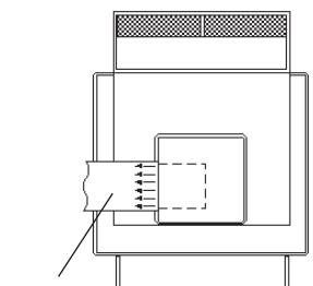
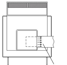
Rear venting:
a. Remove 4 hex nuts that attach blower box to downdraft vent base. Remove blower box.
b. Note how wiring cable is installed under plastic clips inside vent base. Then carefully remove wiring cable from plastic clips. Disconnect blower wiring cable.
c. Remove 6 Phillips-head screws attaching blower to blower box. Remove blower.
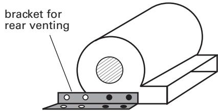
d. Remove screws attaching brackets to each side of blower. Reposition brackets on blower as shown. Then reinstall screws.
e. Reinstall blower in blower box with mouth of blower pointing out open side of blower box. Secure blower to blower box with 6 Phillips-head screws.
NOTE: Square metal frame attached to mouth of blower must be installed for proper operation.
f. Attach metal cover from parts bag over down-venting knockout in blower box. Remove rear knockout cover on back of vent base.
g. Reconnect blower wiring cable. Secure wiring cable in 2 black plastic clips inside vent base.The wiring cable must be properly secured in the 2 clips (see step b.) Reattach blower box to downdraft vent base with 4 hex nuts.
- Attach backdraft damper over blower box knockout with 2 Phillips-head screws.
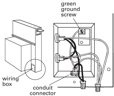
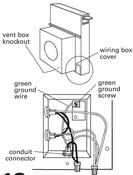
- Remove the 2 Phillips-head screws attaching the wiring box cover. Determine which direction (rear or down) electrical connection will need to run from appliance wiring box. Remove rear or bottom knockout and install conduit connector.
WARNING
Excessive Weight Hazard Use two or more people to move and install downdraft vent.
Failure to do so can result in back or other injury.
- Insert downdraft vent into countertop cutout. Two people are recommended to support the weight of the downdraft vent during lifting. Position downdraft vent so it is centered in cutout and parallel to edge of cutout. Check that downdraft vent is level vertically. Then fasten lower support legs to cabinet floor with screws.

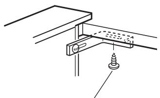
When attaching undercover bracket to underside of countertop, make sure that the screw length will not go through countertop when tightened.
- Attach one undercover bracket on front upper right corner of downdraft vent with slot over vent mounting hole and flange against countertop. Attach other bracket to left side of downdraft vent. Carefully drill starter holes through undercover mounting brackets into underside of countertop. Insert appropriate length screws into holes and tighten brackets to countertop.
WARNING

Electrical Shock Hazard Disconnect power before servicing.
Connect ground wire to green ground screw in terminal box.
Failure to do so can result in death or electrical shock.
- Disconnect power.
-
Remove required knockout and install conduit connector. Feed the power supply cable through the conduit connector and into the wiring box. Connect the white wires together with a twist-on wire connector. Connect the black wires together with a twist-on wire connector. Attach the green (or green and yellow) ground wire to eyelet with green ground screw. Tighten the conduit connector clamp screws. Replace the wiring box cover.
-
Reconnect power.
-
Push and hold for a few seconds the button on the top of the downdraft vent. Retractable section of downdraft vent will rise and blower will start. Position the top trim over the retractable section and snap trim into place.
-
Turn the control knob on side of vent to check the operation and speed of blower. If blower does not operate:
-
Check that filter or filters are pressed in as far as they will go.
- Check that circuit breaker is not tripped or house fuse blown.
- Disconnect power. Check that wire connections have been made correctly.
-
Reconnect power.
-
Connect vent system to blower. Vent system must end with a wall or roof cap. Use duct tape to seal all joints.
-
Install cooktop according to manufacturer's instructions. Check that rear of cooktop overlaps edge of retractable downdraft vent by 3/8'' (9.5 mm).
To get the most efficient use from your new retractable downdraft vent, read the Use and Care Information section on page 12.
Keep Installation Instructions and Use and Care Information close by for easy reference.
Exterior-mounted vent motor
KIRD and YKIRD MODELS ONLY
NOTE: Exterior-mounted vent motor installations require exterior blower system, Model No. KPEC992M [900 cfm (25.5 m³/m)], available from your dealer or authorized parts supplier.
IMPORTANT: Exterior blower Model No. KPEU722M [1200 cfm (34.0 m³/3)] cannot be used with this retractable downdraft vent system.
Installation requirements
Built-in cabinet location
Built-in cabinet location
left vent
right vent
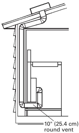
Roof venting
Maximum length of vent system
| Vent | Length |
| 10" (25.4 cm) round | 40 ft. (12.2 m) |
Vent length is given as a general reference only. For a longer vent run, or smaller vent system, contact a qualified and trained vent installer. Check with local codes for makeup air requirements, if any.
For best performance, use no more than three 90^ elbows. If more than one elbow is used, make sure that there is a minimum of 24 inches (61 cm) of straight vent between any two elbows. Do not install two elbows together.
It is recommended that you use round vent instead of rectangular vent, especially if elbows are required. If rectangular vent is required, it should be transitioned to 10^ (25.4 cm) round vent as soon as possible.
Determining the length of system you need:
To calculate the length of system you need, add the equivalent feet for each duct piece that will be needed. See example for 10" (25.4 cm) round vent system.
10" (25.4 cm) round vent system
Maximum length = 40 ft. (12.2m)
$$ 2 - 9 0 \text {e l b o w s} = 1 0 \text {f t .} (3. 0 5 \mathrm {m}) $$
$$ 1 0 \text {f t .} (3 \mathrm {m}) \text {s t r a i g h t} = 1 0 \text {f t .} (3. 0 5 \mathrm {m}) $$
$$ \text {L e n g t h} 1 0 ^ {\prime \prime} $$
$$ (2 5. 4 \mathrm {c m}) \text {s y s t e m} = 2 0 \mathrm {f t}. (6. 1 \mathrm {m}) $$
NOTE: The exterior-mounted vent motor requires a separate wiring cable that should be installed at the same time the vent work is installed.
Recommended standard fittings
Installation steps
- Put on gloves and safety glasses. Place cardboard or another form of protection on top of a flat surface where you can easily assemble the downdraft vent system. Remove parts packages, downdraft vent and blower box from carton. Remove all shipping materials, tape and protective film from downdraft vent and blower box.
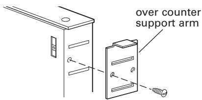
- Attach the left side and right side overcounter support brackets to the downdraft. Use 1 screw with each bracket.
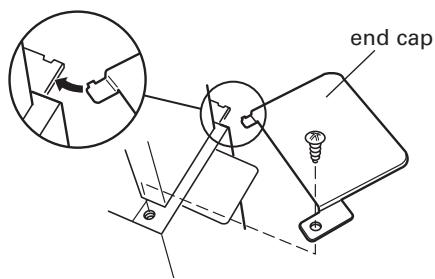
- Attach the left side and right side end caps to the downdraft. Use 1 screw with each end cap.
- Attach support legs to side of downdraft vent with two screws in each leg. Do not tighten screws.
WARNING
Excessive Weight Hazard Use two or more people to move and install downdraft vent. Failure to do so can result in back or other injury.
- Carefully insert downdraft vent into countertop cutout. Two people are recommended to support the weight of the downdraft vent during lifting. Check that downdraft vent is parallel to side of cutout and that mounting brackets rest gently on countertop.
- Move support legs down against cabinet floor. Place a level against front of downdraft vent base and adjust position of legs until downdraft is level vertically. Use a pencil to mark the top of each leg on face of downdraft vent. Then mark location of support leg mounting holes on cabinet floor. Remove downdraft vent from cutout. Drill starter holes at each mounting screw location on
cabinet floor. Align top of legs with pencil marks on face of downdraft vent. Tighten screws in legs.
-
Attach 10'' (25.4 cm) round vent collar plate (supplied with exterior blower system) to front of downdraft vent using 4 hex washer nuts.
-
Remove the 2 Phillips-head screws attaching the wiring box cover and remove cover. Remove either the back or bottom knockout and install conduit connector.
NOTE: Power supply cable needed between exterior blower assembly and blower box is not provided.
- Determine the location where the exterior blower box will be located. Cut opening in roof or wall for vent system to exterior blower. Install exterior blower according to instructions supplied with the blower kit.
Wall Installations:
- Use caulking compound between mounting flange and wall.
Roof Installations: - Follow standard roofing procedures.
- The flashing sheet should be centered over the roof opening.
- Lower edge of flashing should lie on top of shingles and upper edge underneath shingles.
-
Seal assembly between roof, fan and flashing with roofing mastic to prevent leaks.
-
Insert retractable downdraft vent into countertop cutout. Two people are recommended to support the weight of the downdraft vent during lifting. Position downdraft vent so it is centered in cutout and parallel to edge of cutout. Check that downdraft vent is vertical. Then attach lower support legs to cabinet floor with screws.
When attaching undercover bracket to underside of countertop, make sure that the screw length will not go through countertop when tightened.
- Attach one undercounter mounting bracket on front upper right corner of downdraft vent with slot over vent mounting hole and flange against countertop. Attach other bracket to left side of downdraft vent. Carefully drill starter holes through undercounter mounting brackets into underside of countertop. Insert appropriate length screws into holes and tighten brackets to countertop.
WARNING

Electrical Shock Hazard
Disconnect power before servicing.
Connect ground wire to green ground screw in terminal box.
Failure to do so can result in death or electrical shock.
- Disconnect power.
- Feed the power supply cable through the conduit connector and into wiring box. Connect the white wires together with a twist-on wire connector. Connect the black wires together with a twist-on wire connector. Attach the green (or green and yellow) ground wire to eyelet with green ground screw and tighten screw. Replace wiring box cover.
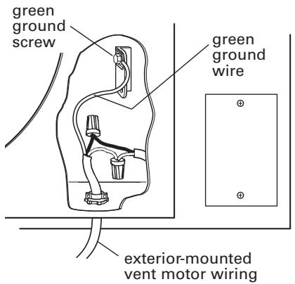
- Remove vent box knockout and install conduit connector.
Feed exterior-mounted vent motor wiring through conduit connector.
IMPORTANT: Do not wire the exterior vent motor black and white wires into the wiring box. Wires must be connected as shown. Connect the white wires together with a twist-on wire connector. Connect the black wires together with a twist-on connector.
Attach ground wire to eyelet with green ground screw and tighten screw.
Tighten conduit connector clamp screws.
- Reconnect power.
-
Push and hold for a few seconds the button on the top of the downdraft vent. Retractable section of downdraft vent will rise and blower will start. Position the top trim over the retractable section and snap trim into place.
-
Turn the control knob on side of vent to check the operation and speed of blower. If blower does not operate:
-
Check that filter or filters are pressed in as far as they will go.
- Check that circuit breaker is not tripped or house fuse blown.
-
Reconnect power. Check that wire connections have been made correctly.
-
Connect vent to blower. Position vent to avoid wall studs and floor joists. Complete all vent work. Use duct tape to seal all joints. Vertical vent for wall-mounted installations should pitch down slightly toward the vent to allow moisture to run outside.
-
Install cooktop according to manufacturer's instructions. Check that rear of cooktop overlaps edge of retractable downdraft vent by 3/8'' (9.5 mm).
To get the most efficient use from your new retractable downdraft vent, read the Use and Care Information section on page 12.
Keep Installation Instructions and Use and Care Information close by for easy reference.
Use and Care Information
The retractable downdraft vent system is designed to remove smoke, cooking vapors and odors from the cooktop area. For the best results, the vent should be operating before cooking is started. If you use large or tall utensils, place them on the large rear element or burner surface. A higher heat setting than normally used may be needed when the downdraft vent is operating.
WARNING - TO REDUCE THE RISK OF FIRE, ELECTRIC SHOCK, OR INJURY TO PERSONS, OBSERVE THE FOLLOWING:
Use this unit only in the manner intended by the manufacturer. If you have questions, contact the manufacturer. Before servicing or cleaning unit, switch power off at service panel and lock the service disconnecting means to prevent power from being switched on accidentally. When the service disconnecting means cannot be locked, securely fasten a prominent warning device such as a tag to the service panel.
CAUTION: For general ventilating use only. Do not use to exhaust hazardous or explosive materials and vapors.
WARNING - TO REDUCE THE RISK OF A RANGE TOP GREASE FIRE:
Never leave surface units unattended at high settings. Boilovers cause smoking and greasy spillovers that may ignite. Heat oils slowly on low or medium settings.
Always turn hood ON when cooking at high heat or when cooking flaming foods.
Clean ventilating fans frequently. Grease should not be allowed to accumulate on fan or filter.
Use proper pan size. Always use cookware appropriate for the size of the surface element.
WARNING - TO REDUCE THE RISK OF INJURY TO PERSONS IN THE EVENT OF A RANGE TOP GREASE FIRE, OBSERVE THE FOLLOWING:
SMOTHER FLAMES with a close-fitting lid, cookie sheet, or metal tray, then turn off the burner. BE CAREFUL TO PREVENT BURNS.
If the flames do not go out immediately, EVACUATE AND CALL THE FIRE DEPARTMENT.
NEVER PICK UP A FLAMING PAN — You may be burned.
DO NOT USE WATER, including wet dishcloths or towels — a violent steam explosion will result. Use an extinguisher ONLY if:
You know you have a Class ABC extinguisher, and you already know how to operate it.
The fire is small and contained in the area where it is started.
The fire department is being called.
You can fight the fire with your back to an exit.
This fan is suitable for use with solid-state speed controls.
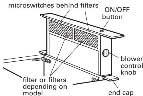
Operating downdraft vent
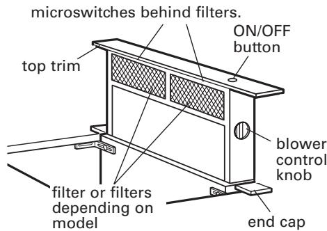
Push and hold for a few seconds the button on top of downdraft vent. This slight delay prevents raising the vent during cleaning. Retractable section of downdraft vent will rise and blower will begin to vent. Turn knob on side of downdraft vent to adjust the setting to the amount of venting you need. The knob has infinite settings. Place cooking utensils on cooking surface and turn cooking unit on. When cooking is complete, turn cooking unit off, remove utensils from cooking surface, and push button on top of retractable downdraft vent. The blower will turn off and the retractable section of the vent will return to the closed position.
If a spill occurs on the cooktop that allows liquids to seep inside the downdraft, you must turn the downdraft off immediately. It is possible to cause damage to the downdraft if water is allowed inside the downdraft while it is operating.
- Immediately turn OFF the downdraft at the speed control located on the right-hand side of the downdraft.
- Turn OFF the power supply to the downdraft at the circuit breaker box or fuse box.
- Allow plenty of time for the downdraft to dry naturally. Do not open the downdraft to remove the water.
Cleaning
Surface of downdraft vent: Clean with soap and water. Do Not use scouring powder or abrasive solutions.
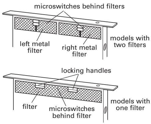
Filter or filters (depending on model): Frequently remove and clean the filters in the retractable section of the downdraft vent. This will improve the operating efficiency of the downdraft vent system.
- Remove the filter(s) and clean them in the dishwasher or in a hot detergent solution.
Do not use the downdraft vent when the filter(s) is not in place. - Reinstall the clean filter(s), making sure that they are pushed in as far as they will go.
NOTE: Downdraft vent will not operate if filter(s) is not in proper position. If the handle(s) is not fully locked, the vent may retract but not raise back up.
If retractable downdraft vent does not operate after clean filters have been reinstalled:
Push the filter in as far as it will go. When the filter is removed, the microswitch behind the filter is inactivated. This safety feature stops the blower and raising mechanism until the filter is properly reinstalled.
Accessories
available from your dealer
NOTE: Instructions are included with each kit.
For model series
KIRD & YKIRD 801, 802
30" (76.2 cm) one-piece trim:
Part No. 8171304 (white)
Part No. 8171305 (black)
Part No. 8171306 (biscuit)
For model series
KIRD &YKIRD 861,862
36" (91.4 cm) one-piece trim:
Part No. 8171310 (white)
Part No. 8171311 (black)
Part No. 8171312 (biscuit)
For model series
GZ&YGZ7930
30" (76.2 cm) one-piece trim:
Part No. 8171300 (white)
Part No. 8171301 (black)
Part No. 8171370 (biscuit)
For model series
GZ&YGZ7736
36" (91.4 cm) one-piece trim:
Part No. 8171302 (white)
Part No. 8171303 (black)
Part No. 8171371 (biscuit)
KITCHENAID® VENTILATION WARRANTY
ONE YEAR LIMITED WARRANTY
For one year from the date of purchase, when this major appliance is operated and maintained according to instructions attached to or furnished with the product, KitchenAid or KitchenAid Canada (hereafter "KitchenAid") will pay for factory specified parts and repair labor to correct defects in materials or workmanship. Service must be provided by a KitchenAid designated service company.
ITEMS KITCHENAID WILL NOT PAY FOR
- Service calls to correct the installation of your major appliance, to instruct you how to use your major appliance, to replace or repair house fuses or to correct house wiring or plumbing.
- Service calls to repair or replace appliance light bulbs, air filters or water filters. Those consumable parts are excluded from warranty coverage.
- Repairs when your major appliance is used for other than normal, single-family household use.
- Damage resulting from accident, alteration, misuse, abuse, fire, flood, acts of God, improper installation, installation not in accordance with electrical or plumbing codes, or use of products not approved by KitchenAid.
- Replacement parts or repair labor costs for units operated outside the United States or Canada.
- Pickup and delivery. This major appliance is designed to be repaired in the home.
- Repairs to parts or systems resulting from unauthorized modifications made to the appliance.
- Expenses for travel and transportation for product service in remote locations.
- The removal and reinstallation of your appliance if it is installed in an inaccessible location or is not installed in accordance with published installation instructions.
DISCLAIMER OF IMPLIED WARRANTY; LIMITATION OF REMEDIES
CUSTOMER'S SOLE AND EXCLUSIVE REMEDY UNDER THIS LIMITED WARRANTY SHALL BE PRODUCT REPAIR AS PROVIDED HEREIN. IMPLIED WARRANTY, INCLUDING WARRANTY OF MERCHANTABILITY OR FITNESS FOR A PARTICULAR PURPOSE, ARE LIMITED TO ONE YEAR OR THE SHORTEST PERIOD ALLOWED BY LAW. KITCHENAID SHALL NOT BE LIABLE FOR INCIDENTAL OR CONSEQUENTIAL DAMAGES. SOME STATES AND PROVINCES DO NOT ALLOW THE EXCLUSION OR LIMITATION OF INCIDENTAL OR CONSEQUENTIAL DAMAGES, OR LIMITATIONS ON THE DURATION OF IMPLIED WARRANTY OF MERCHANTABILITY OR FITNESS, SO THESE EXCLUSIONS OR LIMITATIONS MAY NOT APPLY TO YOU. THIS WARRANTY GIVES YOU SPECIFIC LEGAL RIGHTS AND YOU MAY ALSO HAVE OTHER RIGHTS, WHICH VARY FROM STATE TO STATE OR PROVINCE TO PROVINCE.
Outside the 50 United States and Canada, this warranty does not apply. Contact your authorized KitchenAid dealer to determine if another warranty applies.
If you need service, first see the "Troubleshooting" section of the Use & Care Guide. After checking "Troubleshooting," additional help can be found by checking the "Assistance or Service" section or by calling KitchenAid. In the U.S.A., call 1-800-422-1230. In Canada, call 1-800-807-6777. 10/05
WHIRLPOOL CORPORATION MAJOR APPLIANCE WARRANTY
ONE YEAR LIMITED WARRANTY
For one year from the date of purchase, when this major appliance is operated and maintained according to instructions attached to or furnished with the product, Whirlpool Corporation or Whirlpool Canada LP (hereafter "Whirlpool") will pay for FSP® replacement parts and repair labor to correct defects in materials or workmanship. Service must be provided by a Whirlpool designated service company.
ITEMS WHIRLPOOL WILL NOT PAY FOR
- Service calls to correct the installation of your major appliance, to instruct you how to use your major appliance, to replace or repair house fuses or to correct house wiring or plumbing.
- Service calls to repair or replace appliance light bulbs, air filters or water filters. Those consumable parts are excluded from warranty coverage.
- Repairs when your major appliance is used for other than normal, single-family household use.
- Damage resulting from accident, alteration, misuse, abuse, fire, flood, acts of God, improper installation, installation not in accordance with electrical or plumbing codes, or use of products not approved by Whirlpool.
- Any food loss due to refrigerator or freezer product failures.
- Replacement parts or repair labor costs for units operated outside the United States or Canada.
- Pickup and delivery. This major appliance is designed to be repaired in the home.
- Repairs to parts or systems resulting from unauthorized modifications made to the appliance.
- Expenses for travel and transportation for product service in remote locations.
- The removal and reinstallation of your appliance if it is installed in an inaccessible location or is not installed in accordance with published installation instructions.
DISCLAIMER OF IMPLIED WARRANTY; LIMITATION OF REMEDIES
CUSTOMER'S SOLE AND EXCLUSIVE REMEDY UNDER THIS LIMITED WARRANTY SHALL BE PRODUCT REPAIR AS PROVIDED HEREIN. IMPLIED WARRANTYES, INCLUDING WARRANTYES OF MERCHANTIBILITY OR FITNESS FOR A PARTICULAR PURPOSE, ARE LIMITED TO ONE YEAR OR THE SHORTEST PERIOD ALLOWED BY LAW. WHIRLPOOL SHALL NOT BE LIABLE FOR INCIDENTAL OR CONSEQUENTIAL DAMAGES. SOME STATES AND PROVINCES DO NOT ALLOW THE EXCLUSION OR LIMITATION OF INCIDENTAL OR CONSEQUENTIAL DAMAGES, OR LIMITATIONS ON THE DURATION OF IMPLIED WARRANTYES OF MERCHANTABILITY OR FITNESS, SO THESE EXCLUSIONS OR LIMITATIONS MAY NOT APPLY TO YOU. THIS WARRANTYY GIVES YOU SPECIFIC LEGAL RIGHTS AND YOU MAY ALSO HAVE OTHER RIGHTS, WHICH VARY FROM STATE TO STATE OR PROVINCE TO PROVINCE.
Outside the 50 United States and Canada, this warranty does not apply. Contact your authorized Whirlpool dealer to determine if another warranty applies.
If you need service, first see the "Troubleshooting" section of the Use & Care Guide. After checking "Troubleshooting," additional help can be found by checking the "Assistance or Service" section or by calling Whirlpool. In the U.S.A., call 1-800-253-1301. In Canada, call 1-800-807-6777.
Requesting Assistance or Service in U.S.A.
Identify the brand of your vent system and, as appropriate, call the KitchenAid Customer Interaction Center toll-free at 1-800-422-1230 or call the Whirlpool Customer Interaction Center toll-free at 1-800-253-1301. Our consultants are available to assist you.

When calling: Please know the purchase date, and the complete model and serial number of your appliance. This information will help us better respond to your request.
Our consultants provide assistance with:
-
Features and specifications on our full line of appliances
-
Installation information
Use and maintenance procedures - Accessory and repair parts sales
- Specialized customer assistance (Spanish speaking, hearing impaired, limited vision, etc.)
- Referrals to local dealers, service companies, and repair parts distributors
Whirlpool-designated service technicians are trained to fulfill the product warranty and provide after-warranty service, anywhere in the United States.
To locate the designated service company in your area, you can also look in your telephone directory Yellow Pages.
If you need replacement parts
If you need to order replacement parts, we recommend that you only use factory-authorized parts. These parts will fit right and work right, because they are made to the same exacting specifications used to build every new Whirlpool or KitchenAid appliance.
To locate factory-authorized parts in your area, call our Customer Interaction Center telephone number, your nearest authorized service center, or Factory Service at 1-800-442-1111.
For further assistance
If you need further assistance, you can write to Whirlpool Corporation or KitchenAid with any questions or tell us about your concerns at:
Customer Interaction Center
c/o Correspondence Dept.
2000 North M-63
Benton Harbor, MI 49022-2692
Please include a daytime phone number in your correspondence.
Requesting Assistance or Service in Canada
Call toll-free, 8:30 a.m. to 6 p.m. (EST) at 1-800-422-1230. Or contact your nearest Inglis Limited or Kitchenaid Canada Appliance Service branch or designated servicing outlet (see list at right) to service your appliance.

When asking for assistance or service, please provide a detailed description of the problem, your appliance's complete model and serial numbers, and the purchase date. This information will help us respond properly to your request.
| Direct service branches: | ||
| BRITISH COLUMBIA | 1-800-665-6788 | |
| ALBERTA | 1-800-661-6291 | |
| ONTARIO | Ottawa area | 1-800-267-3456 |
| (except 807 area code) | Outside the Ottawa area | 1-800-807-6777 |
| MANITOBA, SASKATCHEWAN | 1-800-665-1683 | |
| and 807 area code in ONTARIO | ||
| QUEBEC | Montreal (except South Shore) | 1-800-361-3032 |
| South Shore Montreal | 1-800-361-0950 | |
| Quebec City | 1-800-463-1523 | |
| Sherbrooke | 1-800-567-6966 | |
| ATLANTIC PROVINCES | 1-800-565-1598 | |
For further assistance
If you need further assistance, you can write to Inglis Limited or KitchenAid Canada with any questions or concerns at:
Consumer Relations Department
1901 Minnesota Court
Mississauga, Ontario L5N 3A7
Please include a daytime phone number in your correspondence.
- National Fire Protection Association
One Batterymarch Park
Quincy, Massachusetts 02269
** CSA International
8501 East Pleasant Valley Rd.
Cleveland, Ohio 44131-5575
Raccords standard recommends
GARANTIE DES GROS APPAREILS MÉNAGERS WHIRLPOOL CORPORATION
GARANTIE LIMITEE DE UN AN
1901 Minnesota Court
Mississauga, Ontario L5N 3A7