Hyper Mx - Washing machine CECOTEC - Free user manual and instructions
Find the device manual for free Hyper Mx CECOTEC in PDF.


| Product type | Electric scooter (moped) |
| Brand | Cecotec |
| Model | Hyper MX |
| Power supply | Rechargeable battery |
| Motor | Electric motor |
| Brakes | Front and rear brakes |
| Starting | Key ignition |
| Locking | Integrated locking device |
| Seat opening | Yes, with the key |
| Lighting | Front headlight and rear lights |
| Instrumentation | Speedometer and battery indicator |
| Safety | Recommended protective equipment |
| Comfort | Ergonomic seat |
| Maintenance | Regular cleaning and component checks |
| Spare parts | Available from Cecotec technical service |
| Repairability | Technical assistance for repair |
| Recycling | Compliant with WEEE directives |
| Warranty | Official Cecotec warranty |
| Documentation | Multilingual user manual included |
| Usage | Daily urban mobility |
Frequently Asked Questions - Hyper Mx CECOTEC
User questions about Hyper Mx CECOTEC
0 question about this device. Answer the ones you know or ask your own.
Ask a new question about this device
Download the instructions for your Washing machine in PDF format for free! Find your manual Hyper Mx - CECOTEC and take your electronic device back in hand. On this page are published all the documents necessary for the use of your device. Hyper Mx by CECOTEC.
USER MANUAL Hyper Mx CECOTEC
ÍNDICE
- Parts and components 61
- Vehicle identification 64
- Safety 66
- Before use 68
- Protective equipment and clothing 69
- Operation 69
- Brakes 77
- Parking 77
- Locking device 78
- Seat opening 79
- Battery 80
- Emergencies 89
- Cleaning and maintenance 89
- Technical specifications 105
- Recycling of electrical and electronic equipment 107
- Technical support and warranty 108
- Copyright 108
INDEX
EU01_115414_CECOTEC Hyper MX
EN • The coding in this manual is generic and applies to all code variants of the appliance.
1. PIEZAS Y COMPONENTES
1.1. Componentes generales

Figura 1. Vista trasera del scooter
Figura 6. Arranque mediante tarjeta NFC
Figura 9. Sistema de frenos
8. PARKING.
Figura 11. Asiento
Nota





Main frame protective panel

Thank you for choosing the Cecotec Hyper MX model for your electric mobility!
We invite you to explore this instruction manual, designed to familiarise you with your electric scooter and to help you make the most of its features during your daily journeys.
Here you will find not only instructions on how to operate the vehicle, but also useful advice for its operation and maintenance, all with the aim of ensuring your safety and preserving the value of your investment. Additionally, we provide you with valuable recommendations for riding efficiently and in an environmentally friendly manner.
Cecotec wishes your experience with your electric scooter to be rewarding and for every journey to be filled with exciting and safe moments. Happy riding!
cecòtec
ENGLISH
We recommend that you read this manual thoroughly, focusing particularly on the safety instructions. Here you will find all the relevant information for using your Hyper MX optimally.
It is important to note that the information provided in this manual reflects the most recent version available of the Hyper MX model at the time of its publication or printing. Cecotec reserves the right to make modifications at any time, so we recommend that you always review the most up-to-date version of this manual, which can be found on our website or by scanning the QR code provided in this manual. You can also access this manual in other languages by scanning the QR code. In case of discrepancies between the translated versions and this manual, the information in Spanish shall prevail. Total or partial reproduction of this manual is prohibited without written authorisation from Cecotec.
The figures in this manual may show optional accessories fitted (which are not included as standard), as well as components that may have a different colour from the actual product.

1. PARTS AND COMPONENTS
1.1. General components
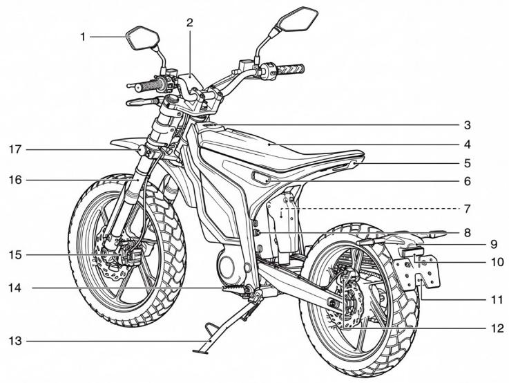
Fig. 1. Rear view of the scooter
1 Rear-view mirror
2 Instrument panel
3 NFC card detection area
4 Seat cushion
5 Tail light
6 Charging port
7 Rear shock absorber
8 Seat cushion lock
9 License plate light
10 Rear reflector
11 License plate bracket
12 Rear brake
13 Side kickstand
14 Rider footrest
15 Front brake
ENGLISH
16 Front shock absorber
17 Side reflector
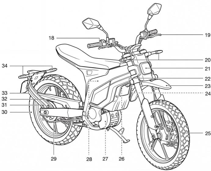
Fig. 2. Front view of the scooter
18 Front brake lever
19 Rear brake lever
20 Front turn signal (Hyperide-S)
21 Front headlight
22 Horn
23 Front mudguard
24 Steering lock
25 Front wheel
26 Motor controller
27 Drive motor
28 Power battery compartment
29 Chain
30 Rear wheel
31 Kickstand cover
32 Chain guard
33 Rear mudguard
34 Rear turn signal
1.2. Instrument panel
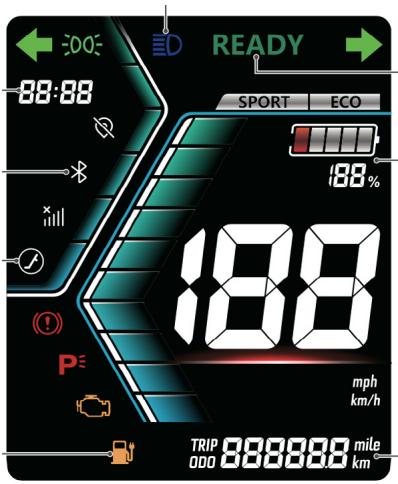
Fig. 3. Instrument panel (display)
| Indicator | Function | Indicator | Function |
 | Ignition |  | Turn signal indicators |
 | High-beam lights indicator |  | Battery charge level |
 | Bluetooth indicator |  | Speedometer (kmh / mph) |
 | Side kickstand indicator |  | Disconnected signal indicator |
 | GPS disconnection indicator |  | Brake engaged indicator |
 | Parking indicator |  | Motor fault warning |
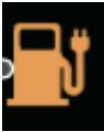 | Low battery warning |  | Mileage indicator and error code display.This indicator can switch between total and trip mileage.When an error occurs in the vehicle, it will be displayed here. |
 | Running lights and low-beam lights |  | Riding mode indicator |
2. VEHICLE IDENTIFICATION
The VIN number is used to identify the scooter as well as to order spare parts.
On this model, the VIN number is located on the right side of the steering column, as indicated in the figure:

Fig. 3. VIN number
However, the scooter also has an information label which includes data such as the maximum permitted mass, the chassis number, and the revolutions per minute of the electric motor.

Fig. 4. Information label
ENGLISH
Additionally, beneath the motor, there is the electric motor nameplate.

Fig. 5. Electric motor nameplate
3. SAFETY
3.1 General safety code
- The vehicle rider must hold the appropriate driving license to operate this vehicle. The vehicle must not be driven without the corresponding driving license.
- Correct use of a helmet is essential and mandatory for both rider and passenger. The helmet must be approved, in good condition, and properly fastened.
- Eye protection is recommended, either through the helmet visor or suitable glasses.
- Do not drink alcohol or consume drugs before riding: your reflexes will be impaired and thus your ability to handle unexpected situations. Do not allow others to ride in this condition either.
- It is your responsibility to inspect and maintain your vehicle before riding, following the instructions in this manual (refer to section "12. Cleaning and maintenance"). Inadequate or no maintenance poses a risk factor.
- Please read section "4. Before use" carefully for detailed instructions. Compliance with these guidelines ensures your safety and that of your passengers while riding.
- Do not exceed the load limits specified for your scooter (indicated in section "13. Technical specifications"). Excess weight can affect vehicle stability and control, increasing the risk of accidents.
- Distribute the load evenly and ensure it is properly secured.
- If you are taking medication that may affect your motor skills or reaction capacity, avoid riding. Consult your doctor about the possible side effects of any medication before riding.
3.2. General warnings
3.2.1. Brakes
- If brake fluid comes into contact with skin, wash the affected area immediately with water.
- If brake fluid comes into contact with eyes, rinse with water and seek medical attention quickly.
- Brake fluid can damage the vehicle paintwork and plastic components in case of accidental spillage. Brake fluid can cause damage and injury if not handled properly and safely.
- If you find excessive play in the brake lever, but the brake pads are still in good condition, contact Cecotec's Official Technical Support Service as soon as possible for inspection. Excessive play refers to the additional or unusual movement you may feel in the brake lever before the brakes begin to operate effectively.
3.2.2. Using the scooter
- This vehicle is NOT designed for motorway use. The vehicle is designed to operate at a constant 80 km/h without causing overheating to any critical component. If the vehicle is used above these specifications, it could overheat.
- Normal use is considered to be use at least once per week. If the vehicle is not going to be used in this manner, it should be left fully charged if it is to remain stationary for an extended period.
- A full charge must be performed every 30 days to ensure proper battery operation and maintain its service life. Failure to follow this guideline may affect the product's legal warranty.
- The instructions indicated in this instruction manual have been written for strictly urban use. When usage conditions differ, more stringent and frequent maintenance will be required.
- If the scooter is affected by an accident, contact Cecotec's Official Technical Support Service. They will carry out the necessary inspections and assessments to determine the vehicle's condition.
- Always follow the instructions and recommendations provided in the manual; failure to do so could result in a serious accident.
- Make use of the instruction manual at all times and ensure you understand all the information contained within it.
- As indicated in the manual, when performing any maintenance, cleaning, or repair operations on the scooter, ensure the vehicle is switched off with the keys removed to prevent accidents caused by any operating components of the scooter.
- Some scooter components such as the motor, brakes, or battery may reach high temperatures; take care not to come into contact with these parts.
3.2.3. Connector
Prevent the connector from coming into contact with any liquid under any circumstances.
ENGLISH
3.2.4. Load (weight)
Never exceed the scooter's maximum permitted load and position it as centrally as possible in a balanced manner (indicated in section "13. Technical specifications").
3.2.5. Battery
For warnings related to battery use, refer to section: "10.5. Battery use, precautions".
3.2.6. Spare parts
Always use original Cecotec spare parts and components. The use of spare parts or replacements that are not compatible with the vehicle may affect its safety and service life.
4. BEFORE USE
Ensure you check the following elements before riding your scooter, which will guarantee your safety on the road. Riders must ensure the scooter is in good condition. Any scooter component may be damaged if exposed to long-term storage. If exposed to adverse weather conditions for extended periods, it can cause braking system corrosion or decreased tyre pressure, which seriously affects the overall performance of the scooter. In addition to a simple surface inspection, the following checks are necessary before use:
- The power supply circuit, by checking the battery cable, and the lighting circuit, by checking if all lights illuminate.
- Condition of the handlebar and front and rear wheels.
- Tyre pressure (indicated in section "13. Technical specifications"). Riding with different tyre pressure than indicated or excessive wear may cause an accident or damage to the scooter itself. Make adjustments if necessary.
- If the reflector is damaged or dirty.
- Check if the battery needs to be charged.
- Check the brake operating system; if you feel the brakes are too soft, visit the authorised dealer for inspection.
- Check the condition of brake pad wear and never reach their limit.
- Check the brake fluid level.
- Check the operational status of lights, turn signals, indicators and horn. Make adjustments if necessary.
- Check the tyre wear condition and that the tread depth is sufficient (greater than 1.6 millimetres).
- Check whether the throttle grip rotates smoothly and if the return is normal.
- Check whether steering rotation is normal.
-
Check whether the side kickstand can be opened and retracted without problems.
-
Respect the vehicle's maximum load (indicated in section "13. Technical specifications").
- Ensure the load is properly secured, firmly attached, and avoid loose objects.
If any of the aforementioned elements is not in proper condition and you cannot resolve it, please contact Cecotec's Official Technical Support Service.
5. PROTECTIVE EQUIPMENT AND CLOTHING
- Always wear a helmet: the use of a helmet is essential and mandatory for both the rider and passenger. Ensure it is in good condition, properly fastened and approved. Wearing a helmet significantly reduces the risk and severity of head injuries. Full-face helmets are preferably recommended over open-face models, in bright colours or with reflective elements, and which fit correctly.
- Protect your eyes: always use some form of eye protection, either the helmet visor or suitable glasses.
- Appropriate clothing: opt for bright or reflective coloured garments, close-fitting and of adequate size to ensure better visibility and safety on the road.
- Protective gloves: wear suitable gloves to protect your hands from abrasions, cuts, and bruises.
- Suitable footwear: footwear should fit correctly, have a low heel, and protect the ankles to provide better stability and protection while riding.
6. OPERATION
6.1. NFC card
Your vehicle is equipped with two NFC cards and two mechanical keys.
If you lose the keys or NFC cards, please contact your dealer.
Note:
When using your vehicle, always carry the mechanical key and NFC card with you. After use, store them properly to prevent loss.
Use:
- Place the NFC card in the NFC card detection area (see section "1. Parts and Components") to turn on the vehicle.
ENGLISH
6.2. Mechanical key
The mechanical key supplied with this vehicle can be used to unlock the seat cushion and lock the handlebars. Simply insert the mechanical key into the corresponding lock and turn it in the indicated direction to perform the corresponding operation.

Fig. 6. Mechanical key
6.3. Vehicle start-up
You can start the vehicle using the following methods:
2. Start-up with an NFC card
Bring the NFC card close to the NFC detection area located in front of the vehicle seat (refer to section 6.1.). Once verified, the vehicle will turn on.

Fig. 6. Start-up using NFC card
6.4. Left handlebar controls

Fig. 7. Left handlebar
- Light selection button: ☐/☐ Press the button to switch between high-beam and low-beam lights
- High beam flash button:
Press the button to switch to high beam momentarily only
- Turn ⇔ ⊙ → signal selection button:
Move the lever to activate the left or right turn signal.
- Horn button:
Press the button to sound the horn.
6.5. Right lever controllers

Fig. 8. Right handlebar

- Emergency stop button: ✗ When the vehicle is not in P position, pressing the upper part of this button will turn off the vehicle.
When the vehicle is not in P position, pressing the lower part of this button will put the vehicle in P position.
When the vehicle is in P position, pressing the lower part of this button will release P position and illuminate the READY indicator, indicating that the vehicle is ready to ride.

- Hazard warning lights button:
Pressing this button once will activate the hazard warning lights, while pressing it again will deactivate them
- Power button:

Press and hold to turn on the vehicle.
- Riding mode button: MODE
Press the button to change riding modes.
6.6. Riding modes
The Hyper MX model offers two riding modes between which you can switch:
- SPORT mode:
Sport mode. In this mode, the vehicle operates at full power with enhanced power output. For safety reasons, it is recommended to use this mode once you have become familiar with the vehicle.
- ECO mode:
Economy mode. In this mode, the vehicle's maximum speed and power are limited, making it suitable for use when still becoming familiar with vehicle control or during long-distance journeys.
Switching between riding modes:
- Turn on the vehicle and ensure the side kickstand is retracted.
- Take the vehicle out of P gear and, once the READY indicator illuminates on the instrument panel, press the mode button on the right handlebar to select the desired riding mode.
- Confirm that the selected riding mode is displayed on the instrument panel.
6.7. NFC communication system operation
Introduction:
The NFC wireless communication system allows you to operate the ignition switch without the need for a traditional key.
This system performs a bidirectional verification between the electric scooter and the NFC card to check if the NFC card is registered.
The NFC wireless communication system uses low-intensity radio waves. It may interfere with medical devices (e.g., pacemakers).
Note:
- You must always carry the NFC card with you when getting on or off the electric scooter or while riding it.
- Store your NFC card in a safe place and avoid leaving it anywhere to prevent loss.
Operating range:
The NFC card operates within a range of 25 mm from the NFC reading area.
The NFC wireless communication system may not work correctly in the following environments:
- When there are nearby installations that generate intense radio waves or noise (e.g., television towers, power stations, radio stations, or airports).
- When the NFC card is carried together with wireless communication devices such as
ENGLISH
laptops, radios, or mobile phones.
- When the NFC card is in contact with metal or covered by metallic objects.
Precautions:
Do not bend or squeeze the NFC card forcefully, nor place heavy objects on it.
- Store the NFC card correctly, away from direct sunlight, high temperatures and high humidity.
- Do not scratch or pierce it.
- Keep it away from magnetised products (e.g., magnetised key rings).
- Always keep the NFC card away from electrical products (e.g., televisions, radios, computers, or low-frequency massage devices).
- Keep the NFC card away from liquids. If it gets wet, dry it immediately with a soft cloth.
- When washing the electric scooter, keep the NFC card away from it.
- Do not burn it.
- Do not clean the NFC card in an ultrasonic cleaner.
- If fuel, wax, or grease spills onto the NFC card, clean it immediately.
- Do not disassemble the NFC card.
- Do not lose your NFC card. If you lose it, you will have to register a new one. Contact your authorised dealer for assistance.
- Do not change the scenario or usage conditions, extend the transmission frequency range, or increase transmission power (including adding additional RF power amplifiers) without authorisation. Do not modify the transmitting antenna without permission.
- Do not cause harmful interference to other legitimate radio stations and do not claim protection against harmful interference.
- It must tolerate interference from industrial, scientific, and medical (ISM) applications that radiate radiofrequency energy or from other legitimate radio stations.
- If harmful interference occurs to other legitimate radio stations, stop using the device immediately and take measures to eliminate the interference before continuing to use it.
- Within aircraft, as well as in electromagnetic environment protection areas of radioastronomy observatories, meteorological radar stations, satellite earth stations (including tracking, telemetry and control, ranging, receiving, and navigation stations), and other military and civilian radio stations and airports, which are designated in accordance with national laws, regulations, and standards, the use of micropower devices must comply with electromagnetic environment protection standards and relevant industrial authorities.
- The use of various remote control models is prohibited in an area with a radius of 5000 metres centred on the midpoint of an airport runway.
6.8. Anti-theft alarm system operation
The anti-theft alarm system is designed to reduce the probability of vehicle theft.
When the ignition switch is off and the system is activated, the alarm will trigger if the sensor detects any vibration or movement of the electric scooter.
The anti-theft alarm system uses low-intensity radio waves. It may interfere with medical devices (e.g., pacemakers).
Note:
When the electric scooter battery is low, the anti-theft alarm system may not function.
Anti-theft alarm system failure:
If any of the following situations occur, it means the electric scooter battery is depleted or there is a system fault. Consult your authorised dealer.
- The alarm does not sound.
- The alarm sounds but gradually fades.
- The alarm continues sounding without stopping.
6.9. Kinetic energy recovery function
This scooter features a kinetic energy recovery function that converts kinetic energy generated during downhill riding, coasting and braking into electrical energy through an energy recovery system. This function enables “charging while riding,” which extends the vehicle’s range.
Note:
- This function is not available when the battery charge is below 5% or if the motor/controller temperature is excessively high.
- This function is intended solely as a riding aid and cannot replace mechanical parking brakes.
6.10. Hill Hold function
The Hill Hold function is an auxiliary function designed for use when parking on uphill slopes to prevent the vehicle from moving or sliding backwards on the slope.
■ Activating the function
While parked on an uphill slope, operate the brake lever continuously for more than 1 second. If the vehicle tends to move backwards when releasing the brake lever and the instrument panel displays "R", this indicates that the vehicle has entered Hill Hold mode.
ENGLISH
■ Exiting the function
- Turn the throttle grip to move the vehicle forward.
- Press the P gear button to change the vehicle to P gear mode.
- Press the emergency stop button to turn off the vehicle.
■ Deactivating the function
The Hill Hold function can be deactivated through the app.
6.11. Downhill control function
The downhill control function is an auxiliary system designed for use on steep descents, with the aim of helping the rider control the vehicle's speed more safely and smoothly.
■ Activating the function
This function can be activated automatically when the vehicle is on a downhill slope and the rider has not turned the throttle grip (i.e., is not actively accelerating).
■ Exiting the function
- Turn the throttle grip.
- Operate the brake lever.
■ Deactivating the function
The downhill control function can be deactivated through the app.
Note:
- This function is not available when the battery charge is above 95% or if the motor/controller temperature is excessively high.
- This function is intended solely as a riding aid and cannot replace mechanical parking brakes.
6.12. Vehicle shutdown
To turn off the vehicle, you can use the following methods:
- Touch the NFC detection area with the NFC card that is already linked to your vehicle to turn it off.
- Press and hold the power button on the right handlebar to turn off the vehicle.
7. BRAKES
Release the throttle and press and hold the front or rear brake lever. The brake light at the rear of the vehicle will illuminate simultaneously with braking.
Warning:
- Avoid applying excessive force or performing emergency braking (especially when the vehicle leans during cornering), as this could cause the vehicle to skid or overturn.
- Braking on wet roads can easily cause skidding and create hazards. Reduce speed and ride with caution.
- In situations such as long, steep descents, repeated braking can cause serious brake overheating, which affects brake performance. For safety, operate the front and rear brakes simultaneously and use them intermittently to reduce speed.
Note:
- During riding, when approaching a corner or preparing to stop, apply the brakes in advance.
- Activate the indicator in advance and be aware of lateral and rear traffic. Apply pressure to the front and rear brake levers gently at first, then gradually increase to achieve controlled braking action.

Fig. 9. Braking system
8. PARKING
Use the side kickstand to park the electric scooter on a solid, level surface and lock the handlebars. If you must park on a slightly inclined or soft surface, ensure the vehicle is stable and will not move or tip over.
ENGLISH
- Turn off the vehicle (see section 6.12).
- Lower the side kickstand.
Gently lean the electric scooter to the left until its weight is concentrated on the side kickstand.
- Turn the handlebars fully to the left and lock them (see section 9).
Note:
When leaving the electric scooter, always turn off the vehicle and lock the handlebars to reduce the risk of theft.
9. LOCKING DEVICE
9.1. Handlebar lock
- Turn the handlebars fully to the left.
- Insert the mechanical key into the handlebar lock and turn it anticlockwise to lock the handlebars.
- Gently shake the front of the scooter to ensure the handlebars are properly locked.
Note:
This scooter is designed to lock the handlebars only to the left. Do not attempt to lock them to the right, as this could cause damage to the vehicle.

Fig. 10. Locking device
9.2. Steering unlock
- Insert the mechanical key into the steering lock and turn it clockwise to unlock the steering handle.
- Turn the steering handle left or right to confirm that the steering operates smoothly.
Note:
- Operate the key gently and move the steering handle carefully to avoid damaging components due to excessive force.
- If you have difficulty opening the steering lock, do not use force to unlock it, as this could damage the lock and other scooter components. Contact an authorised dealer for assistance.
10. SEAT OPENING
Opening the seat cushion
- Insert the seat cushion lock key into its lock and turn it clockwise to unlock the seat cushion.

Fig. 10. Seat lock
- Gently lift the rear of the seat cushion, press down at position [A] and hold it down, while simultaneously pulling the seat cushion towards the rear of the scooter.
ENGLISH
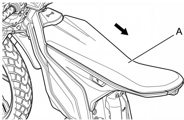
Fig. 11. Seat
Note:
When opening the seat cushion, first ensure it is unlocked and do not force it open to avoid damage.
Installing the seat cushion
- First, insert the seat cushion hooks into the corresponding fixing buckles on the body, then press the seat cushion down until it clicks into place.
- Gently pull the seat cushion upwards to ensure it is properly secured in position.
11. BATTERY
This scooter model is equipped with a power battery located in the centre of the frame.
Caution:
Do not attempt to disassemble or modify the power battery yourself.
Note:
Riding is not recommended in environments with temperatures below -5°C or above 45°C . If the ambient temperature is below -20°C or above 55°C , output will be cut off. Additionally, note that significant variations in actual battery capacity will occur in low-temperature environments.
11.1. Initial considerations:
- With repeated charging and discharging, the battery capacity will gradually decrease. When the battery capacity decreases, although the battery indicator shows it is fully charged, the distance it can travel will gradually shorten.
- Depending on riding conditions and the scooter's service life, the discharge capacity will be gradually affected. The total range may be reduced if the vehicle is ridden under extreme temperature conditions.
11.2. Battery removal and installation
- Remove the seat cushion (see section 10).
- Slide the battery harness connector press plate latch in the direction of arrow 1, tilt the connector press plate upwards 2, grasp the connector and pull it vertically upwards 3 and disconnect the harness connector.
- Grasp the handle and lift the battery upwards to remove it.
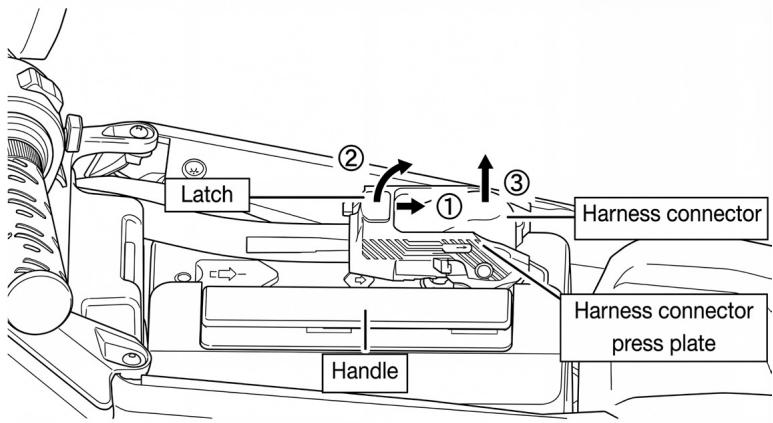
Fig. 12. Battery removal operations
Battery pack installation:
- Reinstall the battery pack into the scooter in its original orientation.
- Connect the harness connector and press down the harness connector press plate.
- Reinstall the seat cushion (see section 10).
11.3. Charger
Store the battery charger in a place away from direct sunlight and rain.
During charging, you can determine the charging status based on the charger indicators.

Fig. 13. Scooter charger
Charger indicators:
| Charger indicators description | |
| Indicator | Description |
| Red and green indicator flashing | Battery not connected |
| Green indicator continuously on | Charging completed |
| Green indicator flashing | Charger updating |
| Red indicator flashing | Charger fault |
| Red indicator continuously on | Charging in process |
Charger usage instructions:
Follow these rules when using the charger:
- To charge, first connect the charger to the mains supply, then to the charging port. It is normal to hear a "click".
- To stop charging, first disconnect the mains plug, then unplug the connector from the vehicle body end.
- This charger is specifically designed for a particular scooter and must not be lent or used interchangeably with other vehicles to avoid damage.
-
When charging, use the original charger and a stable AC power supply.
-
It is prohibited to use unstable power equipment to charge the vehicle. Stop charging when the battery is fully charged and disconnect the charger from the power supply immediately after completing charging.
- This charger is not water-resistant. If the plug or body is immersed in water, stop using it immediately.
- When using the charger, keep it away from explosive gases and be careful of flames or sparks.
- During operation, the charger generates heat. Ensure good ventilation in the environment and do not place it on sofas or other flammable surfaces.
- The charger must be properly earthed. If you are unsure whether the power socket is properly earthed, contact the appropriate personnel for inspection and confirmation.
- The charger contains high-voltage components and must not be repaired or internally modified without authorisation. Contact the Technical Support Service for repairs or replacements.
- Use the charger in a dry, well-ventilated environment, preventing liquids, metallic dust particles, or other foreign bodies from entering the charger, as these could cause internal short circuits and damage.
- Do not charge the electric scooter when it is covered. Ensure good ventilation around the vehicle.
- Avoid charging in areas with risk of thunderstorms.
- Do not plug too many power cables into a single socket. When plugging or unplugging the charger, do not pull directly on the cable.
- Avoid repeatedly recharging the battery once it is fully charged.
- Before use, read this manual carefully. If the red indicator flashes during charging, stop charging immediately, disconnect the charger from the power supply, and have it checked by a professional.
- If the power supply is damaged or the charging system operates incorrectly, please contact your dealer.
Caution:
If a vehicle or battery catches fire due to an accident, follow these principles:
- If the power battery begins to emit smoke, immediately evacuate the vehicle area and contact the fire department.
- Use a dry powder ABC fire extinguisher or electrical fire extinguisher to extinguish the fire. If the fire cannot be controlled, contact the fire department immediately.
- After extinguishing the fire, contact your dealer to dispose of the used battery. Do not attempt to dispose of it yourself.
- Due to different fire locations, the vehicle voltage may not be cut off. Ensure electrical power is disconnected after extinguishing the fire.
ENGLISH
Note:
This charger is only suitable for safe use in areas situated below 2000 metres above sea level.
11.4. Charging the battery
It is essential to use an original or approved charger to charge the power battery. The charger used must be compatible with the battery model.
Complete vehicle charging:
- Open the charging port cover.
- First, connect the charger's connector to the vehicle charging port. Then connect the charger plug to the power socket.
- Once the battery is fully charged, first disconnect the charger's plug from the power socket, then disconnect the charging port connector from the battery. Finally, close the charging port cover and store the charger in a safe place.
External charging
- Remove the battery.
- First, connect the charger's connector to the battery charging port, then connect the charger plug to the power socket.
- Once the battery is fully charged, first disconnect the charger's plug from the power socket, then disconnect the charging port connector from the battery. Close the charging port cover and store the charger in a safe place.
- Reinstall the battery in the vehicle and turn on the vehicle to confirm the battery operates normally.

Fig. 14. Battery charging port
Charging time:
It takes approximately 4 hours to fully charge a power battery from a completely discharged state. At higher or lower ambient temperatures, charging time may be longer. Do not charge for more than 12 hours to avoid affecting battery life.
Note:
The battery may not be able to charge immediately after high-power output or operation under high-temperature conditions. Allow the battery to cool for 30 minutes or more before starting the charging process. This is because the battery management strategy prohibits charging when internal temperature is high, as it may shorten battery life.
11.5. Battery storage, maintenance and transport
- Please charge the battery within an ambient temperature range of 0° C\~ 35° C.
- Do not exceed 10 hours charging time; overcharging will shorten battery life.
- It is strictly prohibited to cover the charger and battery case during charging to facilitate ventilation and heat dissipation.
- Do not disassemble the charger yourself. If replacement is needed, go to an authorised technician for repair or replacement.
- Store the scooter in a level, stable place; keep it in a well-ventilated, dry location.
- Store the battery with a charge level of 30%-50% to ensure its service life.
- Try to avoid exposure to sunlight and rain to reduce damage or ageing of components.
- When storing the battery for an extended period, charge it fully before use.
- For vehicles equipped with batteries stored indoors, in showrooms, warehouses, or transported short distances in cargo vehicles, after turning off and removing the key, remove the battery plug to eliminate possible electrical faults.
Long-term storage:
- When storing for an extended period, disconnect the battery plug after turning off and removing the key to interrupt the battery power circuit (as detailed in section "10.1. Battery removal"), thus avoiding battery over-discharge.
- During long-term storage, perform a complete battery charge and discharge cycle each month and store the battery with a charge level of 30%-50% to ensure battery life.
- When using the vehicle after prolonged storage, ensure the battery is fully charged.
- Before using the vehicle, check the different parts for faults. If you detect any problems, return the vehicle to the dealer for service or repair.
CAUTION:
- The battery is not a user-serviceable component. If there is a malfunction or the battery
ENGLISH
is not fully charged after 10 hours of charging, please stop charging and contact Cecotec's Official Technical Support Service.
- The charging function is disabled when ambient temperature is below 0° C. Please charge the battery in an environment above 0° C.
- Using a non-original charger may cause battery leakage, heat, smoke, fire, or explosion.
- Do not store the battery in an environment above 40° C, as this may cause irreversible capacity degradation.
- At low temperature, the lithium battery capacity will decrease to some extent. The specific reference degree is that usable capacity at -10 °C is 70%, usable capacity at 0 °C is 85%, and usable capacity at 25 °C is 100%.
- The most suitable storage capacity for the battery is 30% to 50%. If storage capacity is below 10% for a long time, it will cause irreversible battery capacity degradation. If the battery is stored for a long time, please keep the battery at -10 °C \~30 °C, and perform a full cycle of charging and discharging for the battery every two months to minimize the attenuation of battery storage.
- Avoid storing the battery in a place with risk of falling, which may cause uncontrollable damage inside the battery and may cause leakage, heat, smoke, fire, or explosion.
11.6. Battery use, precautions
CAUTION
The battery can be an EXTREMELY DANGEROUS element (mortal danger) if not handled correctly. Please follow all the instructions in this manual carefully.
- Keep the battery away from children, fire and heat sources. It is strictly forbidden to throw it into fire. Violent movements, impacts, and extrusion are prohibited. Avoid storing the battery in places with risk of falls, which could cause uncontrollable damage inside the battery and cause leakage, heating, smoke, fire, or explosion.
- Only the specified charger must be used, and the use of other chargers to charge the battery is prohibited. Use of a non-original charger may cause the battery to leak, heat, smoke, catch fire or explode.
- This vehicle has undergone a strict inspection before leaving the factory, and disassembly is strictly prohibited. For any enquiries, please contact Cecotec's Official Technical Support Service.
- Do not expose the vehicle to a room environment above 40 °C for a prolonged period of time, as this may cause irreversible degradation of the vehicle's performance.
- Charging temperature: 0 °C - 35 °C. The charging function is disabled when ambient
temperature is below 0° C. Please charge the battery in an environment above 0° C.
- At low temperatures, the lithium battery capacity will decrease to a certain extent. The specific benchmark is that the usable capacity at -10 °C is 70%, the usable capacity at 0 °C is 85%, and the usable capacity at 25 °C is 100%.
- The most suitable storage capacity for the battery is 30% to 50%. If storage capacity is below 10% for a long time, it will cause irreversible battery capacity degradation. If the battery is stored for a long time, please keep the battery at -10 °C \~30 °C, and perform a full cycle of charging and discharging for the battery every two months to minimize the attenuation of battery storage.
- Only authorised and qualified personnel may handle or disassemble the vehicle battery. If the battery is to be removed for charging, please follow the instructions mentioned in section "11.1. Battery Removal", and note the precautions to follow set out in this section.
- The battery can be exchanged for an identical battery supplied by Cecotec. Only use original Cecotec batteries or batteries compatible with this model as expressly confirmed by Cecotec. Failure to do so may reduce the life of the battery and your vehicle. In the case of battery removal, be sure to handle the battery with care as indicated in this manual.
- The battery should be transported at a low speed in order to avoid strong impacts. Use both hands when transporting the battery and move carefully and slowly.
- Any damage to the battery (impacts, falls, contact with humidity, water or any other liquid, exposure to a heat source, exposure to temperatures above 35 °C) may cause the battery to catch fire.
- If you notice any signs of damage to the battery, avoid connecting it and contact Cecotec's Official Technical Support Service.
- In case of battery fire, it can be extinguished using water or CO2 , unless it is connected to the electrical mains or is near other batteries. In such cases, it is necessary to use a CO2 extinguisher to control the fire and move it to a safe, isolated area, at least 20 metres distant from any exposure, such as other vehicles or batteries. Once in a safe place, it is important to contact emergency services to manage the situation.
- Opening the battery case is strictly prohibited and may represent considerable risk, in addition to completely voiding the warranty. Only authorised personnel are permitted to work on the battery case.
- Disassembling the battery without permission may cause battery leakage, heating, smoke,
ENGLISH
fire or explosion. If smoke is observed coming from the battery, it is of utmost importance to immediately call the fire department and urgently remove it from any enclosed space where it is located.
- The battery is not a user-serviceable component. If there is a malfunction or the battery does not charge completely after 10 hours of charging, please stop charging and contact the Cecotec electric vehicle dealer or Cecotec's Official Technical Support Service.
- Avoid exposing the power battery to water, drinks or corrosive liquids.
- Avoid subjecting the power battery to excessive physical impacts.


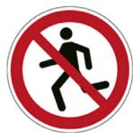


Fig. 15. Warning signals
11.7. General battery warranty aspects
The battery warranty will be voided if any of the following conditions occur during scooter use and storage:
- The scooter has been parked for more than 3 months without undergoing maintenance charging.
- The warranty will not apply to damage caused to the power battery by human factors, such as: accidental vehicle collisions, water immersion, fires, accidents or unauthorised dismantling and modification by the user.
-
The scooter battery charge falls below 10% and is not recharged for 7 days, causing excessive battery discharge.
-
The scooter exceeds the warranty period.
-
The battery is not used in accordance with the manual usage instructions.
12. EMERGENCIES
12.1. First aid and self-help
- In situations involving battery rupture, smoke, or fire, it is essential to prioritise personnel evacuation from the affected area and provide adequate ventilation to disperse gases. It is recommended to seek immediate medical attention.
- In case of eye contact, rinse with abundant water, keeping eyelids open for at least 10 minutes to remove any residue.
- If skin comes into contact with harmful substances, remove contaminated clothing and wash the affected area with soap and water for at least 20 minutes. It is important to avoid applying greases or ointments.
- In case of gas inhalation, move the person to a well-ventilated outdoor area and administer oxygen or perform artificial respiration as necessary.
- In case of brake fluid leakage, if it comes into contact with skin, wash the affected area immediately. If it comes into contact with eyes, perform the same process and seek medical assistance immediately.
12.2. Fire safety measures
- To extinguish a battery fire, Type D, CO2 , and dry chemical extinguishers may be used.
- It is crucial to be aware of specific hazards, such as cell overheating due to external sources or incorrect use.
13. CLEANING AND MAINTENANCE
To extend the scooter's service life and ensure safe and comfortable riding, regular maintenance inspections must be performed. Even during extended periods of vehicle inactivity, periodic inspections must be carried out.
Before starting the vehicle each day, it is essential to perform routine checks. The importance of these checks must never be overlooked. Before riding, ensure all the following inspection points are completed to guarantee optimal performance and achieve safe riding.
13.1. Cleaning
| FREQUENCY: DAILY | ||
| Regular cleaning | Display | Clean with a soft sponge to remove insects or dirt. |
| Seat | Clean with a soft sponge to remove insects or dirt. | |
| FREQUENCY: MONTHLY | ||
| Regular cleaning | Painted parts | Clean with brightener. |
| Rubber parts | Clean with special rubber protection products. | |
| Metal parts | Use oil to clean and grease metal parts. | |
| Instrument panel | Wipe off hardened dirt with a soft sponge. | |
| Lights | Wipe off hardened dirt with a soft sponge. | |
| Suspensions | Check for leaks at both fork and rear shock absorber. | |
Note: do not use harsh detergents, dirty cloths, hard cloths or sponges when cleaning the vehicle as these may damage its components.
13.2. Maintenance
It is essential to maintain your electric scooter in good maintenance and repair condition for your safety, property protection, vehicle performance preservation, and breakdown prevention.
Warning:
- Failure to perform regular maintenance or properly address problems before riding can cause serious or fatal accidents.
- Follow the inspection and maintenance recommendations as well as the maintenance schedule included in this instruction manual.
13.2.1. User inspection
The following checks must be performed by the user before starting:
| Inspection point | Inspection type |
| Tyres. Pressure and tread depth | Visual inspection |
| Chain | Visual inspection |
| Visual inspection of brake fluid lines and connectors | Visual inspection |
| Brake fluid | Visual inspection |
| Brake pads | Visual inspection |
| Brake discs | Visual inspection |
| Wheel rims | Visual inspection |
| Suspension oil | Visual inspection |
| Battery charge level | Visual inspection |
| Battery health | Visual inspection |
| Display operation | Visual inspection |
| Buttons operation | Visual inspection |
| Lights operation | Visual inspection |
13.2.2. Workshop maintenance. Inspection calendar
This regular maintenance will ensure your scooter remains in optimal safety conditions, safeguarding both user and vehicle.
Note:
- Once the complete maintenance plan is finished (>20,000 km), repeat the maintenance plan from the beginning.
- When regularly riding under harsh conditions, such as irregular road surfaces, it is essential to perform maintenance at the frequency indicated in the manual to maintain excellent vehicle performance.
Warning:
- If the vehicle is frequently used at full load, overloaded, at high speeds, on bumpy roads, or on uphill and downhill terrain, carry out user maintenance tasks consistently.
- Original parts are manufactured from superior quality materials and have undergone rigorous validation, guaranteeing both quality and longevity. When performing maintenance and repairs, please use original parts to ensure the vehicle remains in optimal condition, guaranteeing riding safety, and enjoying normal warranty services.
- During routine maintenance and repairs, if any anomaly is detected, it is necessary to clean, inspect, or replace quickly. You may consult simple repair methods or take the vehicle to the dealer for inspection and repair.
Inspection calendar:
| Inspection point | Frequency | ||||||
| First 500 km | Every 500 km | Every 2000 km | Every 3000 km | Every 5000 km | Every 10000 km or 12 months | Every 20000 km or 24 months | |
| Tyres. Pressure and tread depth | Inspection/ Replacement | ||||||
| Chain | Adjustment | Adjustment | Inspection/ Replacement | ||||
| Chain oil | Maintenance | Maintenance | |||||
| Chain guide | Inspection | Visual inspection/ Replacement | |||||
| Front and rear sprocket wear | Inspection | Inspection/ Replacement | |||||
| Visual inspection of brake fluid lines and connectors | |||||||
| Brake fluid | Replacement | ||||||
| Brake pads | Inspection/ Replacement | ||||||
| Brake discs | Inspection/ Replacement | ||||||
| Suspension oil | Maintenance | ||||||
| Battery charge level | |||||||
| Battery health | Inspection | ||||||
| Display operation | |||||||
| Buttons operation | |||||||
| Lights operation | |||||||
| Motor oil | Replacement | Replacement | |||||
| Steering column lubrication | Maintenance | Inspection/Replacement | |||||
| Rear suspension. Bearing and oil seal of rear shock absorber multi-link mechanism | Maintenance | Inspection/Replacement | |||||
| Bearings | Inspection/Replacement | ||||||
| Screw tightening torque | Inspection | ||||||
13.2.3. Brakes
Turn the steering handle and check if the brake fluid level is above the lower limit mark when horizontally aligned with the mark line.
If the brake fluid level in the reservoir is below the lower limit mark
or the brake lever free play exceeds the standard, take your electric scooter to an authorised dealer for inspection and repair.
Recommended brake fluid: DOT 3/DOT 4 brake fluid or equivalent.
Note:
Brake fluid can damage plastic surfaces and paintwork.
If spilled, clean immediately and wipe thoroughly.
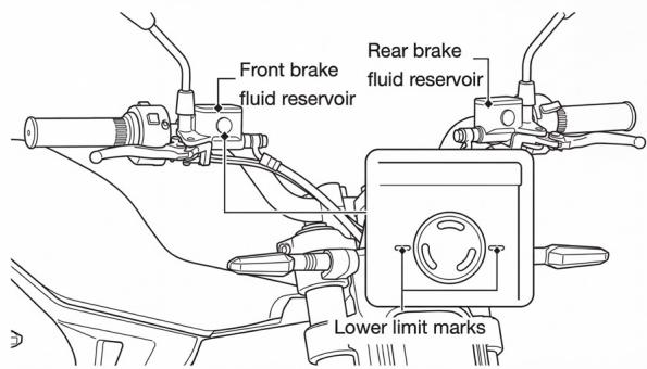
Fig. 16. Brake fluid indicator
ENGLISH
When brake system maintenance or repair is required, please contact the nearest authorised repair department or dealer for inspection. When replacing parts, it is necessary to use original parts from the authorised repair department or dealer.
13.2.4. Tyres
Check tyre pressure visually and with a pressure gauge at least once a month or whenever you consider the pressure is low.
Check tyre pressure when they are cold. The maximum tyre pressures are as follows:
| CECOTEC HYPER MX | |
| Maximum front tyre pressure | 175 kPa |
| Maximum rear tyre pressure | 200 kPa |
Caution:
Riding an electric scooter with inadequate tyre pressure can cause the vehicle to lose control, causing serious damage.
Tyre damage inspection:
Inspect tyres for cuts, cracks, exposed fabric or tyre cords, and nails or other foreign objects embedded in the sidewalls or tread.
Also check for bulges or swelling on the tyre sidewalls.

Fig. 17. Tyre damage inspection
Tread inspection:
Inspect the tyre tread wear indicator marks. If the wear indicator marks are visible, replace the tyres immediately.
Minimum tread depth: 0.8 mm.
Precaution:
Riding with severely worn tyres will degrade the electric scooter's riding performance and increase accident risk.
Follow these rules:
- Use recommended tyres or equivalent with the same size, structure, speed rating, and load capacity.
- The Hyper MX model uses tubeless tyres. Do not install an inner tube in the Hyper MX model's tubeless tyres as excessive heat may cause the tube to burst.
- Do not overload the vehicle. Riding an overloaded vehicle can cause accidents.
- Replacement of all wheels and brake-related parts, including tyres, must be performed by repair personnel with professional competence and operational experience.
Warning:
- Installation of inappropriate tyres can affect vehicle handling and stability, causing accidents that may result in serious injury or even death.
- Use tyres of the recommended size and type as specified in this user manual.
13.2.5. Brake pads and brake discs
Inspect the condition of the front and rear brake pad wear indicator marks.
If the brake pads have worn down to the bottom of the indicator marks, they need replacement. Inspect the wear condition of the front and rear brake discs.
If the thickness of the front and rear brake discs has worn to the manufacturer's specified limit, they need replacement.
1 Operating limit: 4 mm
2 Brake pad operating limit: 1 mm
3 If brake disc thickness is less than 3.0 mm, replacement is necessary.

Fig. 18. Brake pad and disc inspection
Warning:
- Go to your authorised dealer to replace brake pads and ensure left and right brake pads are replaced simultaneously.
- Severe brake pad wear, if not replaced in time, can cause accidents and pose a mortal risk to the user.
13.2.6. Side kickstand
Inspection
- Check that the side kickstand operates correctly. If the side kickstand is stiff or makes strange noises, clean the pivot area and lubricate the pivot bolt with clean grease.
- Check that the spring shows no damage or loss of elasticity.
- Sit on the electric scooter and retract the side kickstand.
Start the motor and lower the side kickstand to maximum.
At this moment, even if you turn the throttle grip, the motor will not operate.
If the motor does not stop operating after lowering the side kickstand
and you can still ride the electric scooter, have it inspected and repaired by your authorised dealer.
13.2.7. Throttle
Inspection
With the vehicle turned off, check if the throttle handle moves smoothly from the fully closed to the fully open position.
If the throttle handle does not operate smoothly or does not return to its original position automatically, take it to your authorised dealer for inspection and repair.

Fig. 19. Throttle inspection
13.2.8. Oil replacement
- Use a maintenance stand to lift the vehicle, ensuring both front and rear wheels are off the ground.
- Use appropriate tools to remove the lower motor protection and right protective panel. Place an oil tray under the motor to collect transmission oil. Remove the oil drain/fill bolt and allow the transmission oil to drain completely.
- Tilt the scooter to one side and add 60 ml of gear oil to the motor.
- Replace the oil drain/fill bolt.
Oil type: GL-4 85W-90
Note:
Due to the specialised process involved in changing gear oil, we recommend it be performed by an authorised dealer.

Fig. 20. Oil fill bolt location
13.2.9. Chain
Inspection
Standard chain slack: 15-25 mm.
Adjustment: Loosen the rear axle nut and lock nut. Adjust chain slack by loosening or tightening the adjustment bolt. While adjusting the chain, ensure the front and rear sprockets are aligned in a straight line to prevent incorrect adjustment from affecting chain life. After adjustment, retighten the rear axle nut and lock nut.
Warning:
A chain that is too loose or too tight can cause the chain to come off or break, posing a potential risk to your safety.
Therefore, go to an authorised workshop periodically for inspection and adjustment.

Fig. 21. Chain inspection
13.2.10. Fuse
The electrical system of this scooter is equipped with multiple overcurrent protection devices, including the fuse, a single-use protection device designed to protect the scooter's circuits. If you observe that some electrical components of the scooter stop working, check whether the fuse has blown.
Fuse inspection and replacement
The fuse on this scooter is located at the rear of the vehicle, beneath the seat cushion. Follow these steps to inspect and replace the fuse:
- Completely disconnect power to the scooter.
- Open and remove the seat cushion.
- Remove the protective panel from the main frame.

Fig. 22. Protection panel
ENGLISH
- Remove the fuse cover and check the condition of fuse 1 and fuse 2.

Fig. 23. Fuse location
- If a fuse has blown, replace it with another of the same specifications at a specialised Cecotec centre.
Note:
- If a fuse blows frequently, contact your dealer to check the electrical system.
- When replacing a fuse, always use one of the same specifications.
13.2.11. Front headlight
In dark or low-light conditions, an electric scooter's headlights
are the main source of illumination. If the headlight beam angle is incorrect, it can cause the beam to point too close or too far, directly affecting the rider's visibility and increasing riding risk. Therefore, periodically check whether the headlight beam angle is correct and adjust if necessary.
Inspection and adjustment method
The front headlight beam adjustment screw is located at the rear of the headlights, as shown in the figure. Follow these steps to adjust:
- Place the scooter in an upright position on the ground and turn on the headlight low-beam lights.
- Sit on the rider's seat and check if the beam angle is correct.
- Use a Phillips screwdriver to adjust the beam angle by turning the adjustment screw left or right until the desired angle is achieved.
Note:
- Changes in the scooter's overall angle can affect the headlight angle. After modifying the
scooter's overall angle, ensure you check and adjust the headlight beam angle.
- Ensure beam adjustment complies with local traffic regulations and relevant standards.

Fig. 24. Front headlight adjustment
13.5. Troubleshooting
| FAULT | CAUSES | SOLUTIONS |
| Does not turn on | Battery connector is not connected | Check if the connector is properly connected |
| Battery is discharged | Charge the battery to a sufficient level to start the vehicle | |
| Does not start after turning on | Side kickstand deployed | Deploy the side kickstand |
| Insufficient battery charge | Charge the battery sufficiently | |
| P button has not been pressed | Press the P button to activate and deactivate parking mode | |
| Abnormal brake lever return or brake switch failure | Contact Cecotec's Technical Support Service | |
| Insufficient power or reduced mileage | Low tyre pressure | Inflate tyres to recommended values |
| Low battery | Charge the battery sufficiently | |
| Vehicle load exceeds maximum permissible mass | Do not exceed the vehicle's maximum permissible load | |
| Overheating in motor, controller, or battery | Contact Cecotec's Technical Support Service | |
| Ambient temperature is too high or too low | Ride within recommended temperature limits | |
| Does not charge | Non-original charger | Charge the scooter only with the authorised original charger |
| Charger cable is loose | Ensure the cable is properly connected to the battery | |
| Horn does not sound | Horn connector is loose | Contact Cecotec's Technical Support Service |
| Horn failure | Contact Cecotec's Technical Support Service | |
| Button panel failure | Contact Cecotec's Technical Support Service | |
| Lights do not illuminate | Light connector loose | Contact Cecotec's Technical Support Service |
| Light failure | Contact Cecotec's Technical Support Service |
Fault codes and signals on the display:
| No | Error code | Fault cause | Solution |
| 1 | F0 | Throttle grip failure | Contact Cecotec's Technical Support Service |
| 2 | F1 | ||
| 3 | F2 | ||
| 4 | F3 | “P” button failure | Contact Cecotec's Technical Support Service |
| 5 | F4 | Brake switch failure | Contact Cecotec's Technical Support Service |
| 6 | F5 | Controller overvoltage | Contact Cecotec's Technical Support Service |
| 7 | F6 | Controller undervoltage | Contact Cecotec's Technical Support Service |
| 8 | F7 | Controller internal voltage failure | Contact Cecotec's Technical Support Service |
| 9 | F8 | Controller internal voltage failure | Contact Cecotec's Technical Support Service |
| 10 | F9 | Controller overcurrent | Try to restart, if not resolved, contact Cecotec's Technical Support Service |
| 11 | FA | Controller phase overcurrent | Try to restart, if not resolved, contact Cecotec's Technical Support Service |
| 12 | Fb | Motor maximum speed protection | Ride with caution and avoid speeding on downhill slopes |
| 13 | FC | Controller overtemperature protection | Allow to cool before riding again. If not resolved, contact Cecotec's Technical Support Service |
| 14 | Fd | Motor overtemperature protection | Allow to cool before riding again. If not resolved, contact Cecotec's Technical Support Service |
| 15 | FE | Motor stall protection | Check for transmission obstructions preventing motor rotation, remove any obstruction and restart. |
| 16 | E0 | Motor overload protection | Check if riding conditions meet the vehicle's maximum performance requirements. |
| 17 | E1 | Motor temperature sensor failure | Contact Cecotec's Technical Support Service |
| 18 | E2 | Temperature sensor failure | Try to restart, if not resolved, contact Cecotec's Technical Support Service |
| 19 | E5 | Controller phase current sensor failure | |
| 20 | E6 | Controller phase current sensor failure | |
| 21 | E7 | Controller phase overcurrent | |
| 22 | E8 | Controller phase overcurrent | |
| 23 | E9 | Controller overvoltage | |
| 24 | EA | Controller overvoltage | |
| 25 | Eb | Motor position sensor failure | Contact Cecotec's Technical Support Service |
| 26 | EC | Controller phase loss failure | Contact Cecotec's Technical Support Service |
| 27 | Ed | ||
| 28 | EE | ||
| 29 | d0 | General controller failure (hardware) | Contact Cecotec's Technical Support Service |
| 30 | d9 | NFC failure | Contact Cecotec's Technical Support Service |
| 31 | dA | Bluetooth failure | Try to restart, if not resolved, contact Cecotec's Technical Support Service |
| 32 | 1d3 | 72 V controller overload | Contact Cecotec's Technical Support Service |
| 33 | 1d4 | 72 V controller short circuit | Contact Cecotec's Technical Support Service |
| 34 | 1d5 | 72 V controller input failure | Contact Cecotec's Technical Support Service |
| 35 | 1dA | Controller communication failure | Contact Cecotec's Technical Support Service |
| 36 | 1dd | Battery communication failure | Contact Cecotec's Technical Support Service |
| 37 | A9 | Instrument panel failure | Contact Cecotec's Technical Support Service |
| 38 | AA | Display communication failure | Contact Cecotec's Technical Support Service |
14. TECHNICAL SPECIFICATIONS
| Model | CECOTEC Hyper MX | |
| Reference | EU01_115414 | |
| Basic parameters | Length x Width x Height (mm) | 1936 x 755 x 1092 |
| Wheelbase (mm) | 1291 | |
| Ground clearance (mm) | 254 | |
| Seat height | 838 | |
| Gross vehicle weight | 95 kg | |
| Maximum permissible mass | 80 kg | |
| Maximum load capacity | 1 passenger | |
| Chassis | Front tyre size | 90/90-17 TF |
| Rear tyre size | 120/70-17 TF | |
| Front suspension | Inverted hydraulic shock absorber S: 140 mm | |
| Rear suspension | Rear radial with multiple connecting struts.Single central shock absorber. 140 mm. | |
| Front braking system | Dual-piston floating brake/φ220 mm disc | |
| Rear braking system | Single-piston floating brake/φ220 mm disc | |
| Transmission | Transmission type | Gear + chain |
| Reduction ratio | 6.95 | |
| Chain specification | 428 UX | |
| Dynamic performance | Maximum design speed | 75 km/h |
| Maximum climbing gradient | <=35 degrees | |
| Range | 70-75 km | |
| Battery | Battery type | Lithium battery |
| Voltage | 72 V | |
| Rated capacity | 35 A | |
| Charger | Charger capacity | Charging: 10 A (830 W) |
| Motor | Type | Centre-mounted permanent magnet synchronous motor |
| Voltage | 72 V | |
| Rated power/maximum power | 3.5 kW/6.4 kW | |
| Torque | 45 Nm | |
| Lubricating oil and capacity | GL 4 85W-90 (60 mL) | |
| Electrical equipment | Lights | FULL LED |
| Instrument panel | 3" colour VA | |
| ECU | Bluetooth/GPS | |
| Location module | 4G | |
| NFC | Yes | |
(1) Range is measured under normal temperature and humidity conditions, on a flat surface, with standard tyre pressure, an 80 kg load, and riding at a constant speed of 45 km/h. Actual values may vary due to factors such as wind speed, road conditions, load, riding habits, and others. The values listed on this specifications page are for guidance only.
(2) The recommended tyre sizes and pressures provided in this manual are for guidance. We recommend you always verify specific information on your tyre markings or consult with the tyre manufacturer to ensure accuracy and suitability for your scooter. This ensures vehicle safety and optimal performance.
Technical specifications may change without prior notice to improve product quality.
15. RECYCLING OF ELECTRICAL AND ELECTRONIC EQUIPMENT
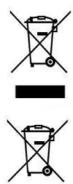
This symbol indicates that, according to the applicable regulations, the product and/or battery must be disposed of separately from household waste. When this vehicle reaches the end of its lifespan, you should remove the batteries/accumulators and take them to a collection point designated by the local authorities. For detailed information on the most appropriate way to dispose of your electrical and electronic equipment and/or batteries, consumers should contact their local authorities.
Compliance with the above guidelines will help to protect the environment.
ENGLISH
16. TECHNICAL SUPPORT AND WARRANTY
Cecotec shall be liable to the end user or consumer for any lack of conformity that exists at the time of delivery of the product under the terms, conditions, and deadlines established by the applicable regulations. Notwithstanding the foregoing, Cecotec shall not be liable to the consumer when the lack of conformity of the product or any part thereof is the result of:
Improper use or maintenance;
A lack of maintenance due to a failure to carry out one of the inspections set out in the product service manual or a repair carried out by an unqualified person;
A modification or alteration of the product or its parts in a manner not authorised or permitted by the manufacturer as described in this manual;
A use other than that intended by the manufacturer, such as, but not limited to, use on rough terrain or uneven surfaces, in competitions.
Non original Cecotec parts or parts not expressly recognised by Cecotec as compatible with the product have been used.
Parts subject to wear and tear (e.g. batteries, tyres, brake discs, brake pads) may reach the end of their service life before the end of the legal warranty period. Therefore, the replacement or repair of these parts resulting from wear and tear, even if the legal warranty period has not expired, will be at the expense of the user.
Batteries must be charged and maintained as described in this manual. If they are subjected to different charging cycles (in terms of frequency and duration) from those specified here, their service life may be reduced.
It is recommended that repairs be carried out by qualified personnel.
If you detect any incident with the product or have any query, please contact Cecotec's Official Technical Support Service on +34 96 321 07 28.
17. COPYRIGHT
The intellectual property rights over the texts in this manual belong to CECOTEC INNOVACIONES, S.L. All rights reserved. The contents of this publication may not, in whole or in part, be reproduced, stored in a retrieval system, transmitted, or distributed by any means (electronic, mechanical, photocopying, recording or similar) without the prior authorization of CECOTEC INNOVACIONES, S.L.
1. PECES I COMPONENTS
1.1. Components generals

Figura 6. Arrencada mitjançant targeta NFC
Figura 9. Sistema de frens
8. PÀRQUING.
Figura 10. Dispositiu de bloqueig
Figura 10. Bloqueig de l'assentament
Figura 11. Seient
Nota
Figura 12. Operacions per retirar la bateria

- ÍNDICE
- INDEX
- PIEZAS Y COMPONENTES
- COMPONENTES GENERALES
- PARKING
- NOTA
- ENGLISH
- PARTS AND COMPONENTS
- GENERAL COMPONENTS
- INSTRUMENT PANEL
- VEHICLE IDENTIFICATION
- SAFETY
- 3.1 GENERAL SAFETY CODE
- GENERAL WARNINGS
- BRAKES
- USING THE SCOOTER
- CONNECTOR
- LOAD (WEIGHT)
- BATTERY
- SPARE PARTS
- BEFORE USE
- PROTECTIVE EQUIPMENT AND CLOTHING
- OPERATION
- NFC CARD
- NOTE
- USE
- MECHANICAL KEY
- VEHICLE START-UP
- START-UP WITH AN NFC CARD
- LEFT HANDLEBAR CONTROLS
- RIGHT LEVER CONTROLLERS
- SPORT MODE
- ECO MODE
- NFC COMMUNICATION SYSTEM OPERATION
- INTRODUCTION
- OPERATING RANGE
- PRECAUTIONS
- ANTI-THEFT ALARM SYSTEM OPERATION
- KINETIC ENERGY RECOVERY FUNCTION
- HILL HOLD FUNCTION
- ACTIVATING THE FUNCTION
- DOWNHILL CONTROL FUNCTION
- VEHICLE SHUTDOWN
- WARNING
- LOCKING DEVICE
- HANDLEBAR LOCK
- STEERING UNLOCK
- SEAT OPENING
- OPENING THE SEAT CUSHION
- INSTALLING THE SEAT CUSHION
- CAUTION
- INITIAL CONSIDERATIONS
- BATTERY REMOVAL AND INSTALLATION
- CHARGER
- CHARGER USAGE INSTRUCTIONS
- FOLLOW THESE RULES WHEN USING THE CHARGER
- CHARGING THE BATTERY
- COMPLETE VEHICLE CHARGING
- EXTERNAL CHARGING
- CHARGING TIME
- BATTERY STORAGE, MAINTENANCE AND TRANSPORT
- LONG-TERM STORAGE
- BATTERY USE, PRECAUTIONS
- GENERAL BATTERY WARRANTY ASPECTS
- EMERGENCIES
- FIRST AID AND SELF-HELP
- FIRE SAFETY MEASURES
- CLEANING AND MAINTENANCE
- CLEANING
- MAINTENANCE
- USER INSPECTION
- WORKSHOP MAINTENANCE. INSPECTION CALENDAR
- TYRES
- MINIMUM TREAD DEPTH: 0.8 MM
- PRECAUTION
- FOLLOW THESE RULES
- BRAKE PADS AND BRAKE DISCS
- SIDE KICKSTAND
- INSPECTION
- THROTTLE
- OIL REPLACEMENT
- CHAIN
- FUSE
- FUSE INSPECTION AND REPLACEMENT
- FRONT HEADLIGHT
- INSPECTION AND ADJUSTMENT METHOD
- TROUBLESHOOTING
- TECHNICAL SPECIFICATIONS
- RECYCLING OF ELECTRICAL AND ELECTRONIC EQUIPMENT
- TECHNICAL SUPPORT AND WARRANTY
- COPYRIGHT
- PECES I COMPONENTS
- COMPONENTS GENERALS
- PÀRQUING
Brand : CECOTEC
Model : Hyper Mx
Category : Washing machine