
SMARTDRIVE COMPACT - Fleet Management System HONEYWELL - Free user manual and instructions
Find the device manual for free SMARTDRIVE COMPACT HONEYWELL in PDF.

| Product type | Frequency converter for asynchronous motors |
| Brand | HONEYWELL |
| Model | SMARTDRIVE COMPACT |
| Dimensions (LxHxD) | MI1: 66x157x98 mm; MI2: 90x195x102 mm; MI3: 100x262.5x109 mm |
| Weight | 0.55 to 0.99 kg depending on size |
| Supply voltage | 208-240 V 1~ or 380-480 V 3~, 50/60 Hz |
| Motor power | 0.25 to 5.5 kW |
| Continuous output current | 1.3 to 12 A depending on model |
| Output frequency | 0-320 Hz |
| Control method | U/f with optimization |
| Interfaces | I/O terminal block, operator panel, Modbus RS485 bus |
| Analog inputs | 2 (0-10 V or 0-20 mA) |
| Analog outputs | 1 (0-20 mA) |
| Digital inputs | 6 (0-30 V) |
| Relay outputs | 2 (250 VAC/2 A) |
| Protections | Overcurrent, overvoltage, undervoltage, overheating, ground fault |
| Protection degree | IP20 |
| Operating temperature | -10°C to +50°C |
| Relative humidity | 0 to 95% non-condensing |
| Maximum altitude | 2000 m (derating above 1000 m) |
| Standards | EN61800-3, EN61800-5-1, UL508C |
| Certifications | CE, UL, cUL, CB |
| Maintenance | External cleaning, check ventilation, discharge time of 5 minutes after power off |
| Safety | Mandatory grounding, do not open under voltage, wait for fan stop |
| Repairability | Spare parts available through Honeywell after-sales service |
Frequently Asked Questions - SMARTDRIVE COMPACT HONEYWELL
User questions about SMARTDRIVE COMPACT HONEYWELL
0 question about this device. Answer the ones you know or ask your own.
Ask a new question about this device
Download the instructions for your Fleet Management System in PDF format for free! Find your manual SMARTDRIVE COMPACT - HONEYWELL and take your electronic device back in hand. On this page are published all the documents necessary for the use of your device. SMARTDRIVE COMPACT by HONEYWELL.
USER MANUAL SMARTDRIVE COMPACT HONEYWELL
Constant and Variable torque
Variable Speed Drives
for Induction Motors
1.SAFETY 2
2. INSTALLATION 3
2.1 MECHANICAL INSTALLATION 3
2.2 CABLING AND CONNECTIONS 5
2.2.1 Power cabling 5
2.2.2 Control cabling 6
- CONTROL I/O AND TERMINALS 7
- NAVIGATION & STARTUP 9
4.1 THE MAIN MENUS OF SMARTDRIVE COMPACT 9
4.2 COMMISSIONING AND STARTUP WIZARD 10
4.2.1 Commissioning steps 10
4.2.2 Startup wizard 10
4.2.3 Manual testing 12
- MONITORING & PARAMETERS 13
5.1 MONITORING VALUES 13
5.2 QUICK SETUP PARAMETERS 14
5.3 SYSTEM MENU PARAMETERS 16
- FAULT TRACING 17
- GENERAL DATA 19
This quick guide includes the essential steps for easy installation and setup of your SmartDrive Compact invert
Before commissioning your drive, read the complete
SmartDrive Compact User Manual available on the CD delivered with your
product or downloadable at:
http://ecc.emea.honeywell.com/inverter
1. SAFETY

ONLY A COMPETENT ELECTRICIAN IS ALLOWED TO CARRY OUT THE ELECTRICAL INSTALLATION

This quick guide contains clearly marked warnings which are intended for your personal safety and to avoid any unintentional damage to the product or connected appliances.
Please read these warnings carefully:

The components of the power unit of the inverter are live when SmartDrive Compact is connected to mains potential. Coming into contact with this voltage is extremely dangerous and may cause death or severe injury.

The motor terminals U, V, W (T1, T2, T3) and the possible brake resistor terminals - / + are live when SmartDrive Compact is connected to mains, even if the motor is not running.

The control I/O-terminals are isolated from the mains potential. However, the relay output terminals may have a dangerous control voltage present even when SmartDrive Compact is disconnected from mains.

The earth leakage current of SmartDrive Compact inverters exceeds 3.5mA AC. According to standard EN61800-5-1, a reinforced protective ground connection must be ensured.
See Chapter 7!

If the inverter is used as a part of a machine, the machine manufacturer is responsible for providing the machine with a main switch (EN 60204-1).

If SmartDrive Compact is disconnected from mains while running the motor, it remains live if the motor is energized by the process. In this case the motor functions as a generator feeding energy to the inverter.

After disconnecting the inverter from the mains, wait until the fan stops and the indicators on the display go out. Wait 5 more minutes before doing any work on SmartDrive Compact connections.

The motor can start automatically after a fault situation, if autorestart function has been activated.
2. INSTALLATION
2.1 MECHANICAL INSTALLATION
Table 1: Mechanical size classes with SmartDrive Compact
| Product code | Mechanical size | Dimensions WxHxD [mm] |
| COMP230-P37-20 | MI1 | 66x157x98 |
| COMP230-P75-20 | ||
| COMP400-P55-20 | ||
| COMP400-P75-20 | ||
| COMP400-1P1-20 | ||
| COMP230-1P1-20 | MI2 | 90x195x102 |
| COMP230-1P5-20 | ||
| COMP400-1P5-20 | ||
| COMP400-2P2-20 | ||
| COMP230-2P2-20 | MI3 | 100x251x109 |
| COMP400-3P0-20 | ||
| COMP400-4P0-20 | ||
| COMP400-5P5-20 |
There are two possible ways to mount SmartDrive Compact in the wall; either screw or DIN-rail mounting.
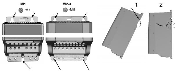
Figure 1: Screw mounting (left) and DIN-rail mounting (right)
NOTE! See the mounting dimensions on the back of the drive.
Leave free space for cooling above (100 mm) and below (50 mm) SmartDrive Compact!
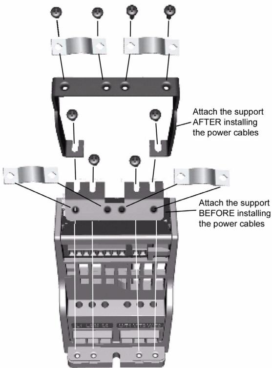
Figure 2: Attaching the PE-plate and cable support
2.2 CABLING AND CONNECTIONS
2.2.1 Power cabling
Note! Tightening torque for power cables is 0.5 - 0.6 Nm
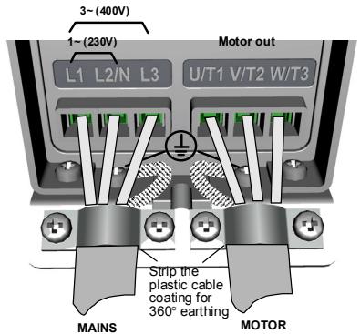
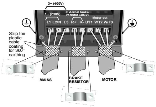
Figure 3: SmartDrive Compact power connections, MI1
Figure 4: SmartDrive Compact power connections, MI2 - MI3
2.2.2 Control cabling
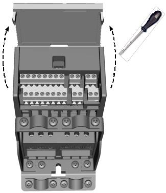
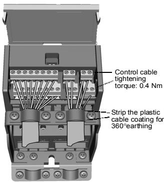
Figure 5: Open the cover
Figure 6: Install the control cables. See next page!
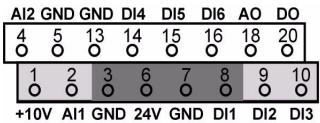
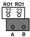
3. CONTROL I/O AND TERMINALS
Table 1: Default I/O configuration and connections P) = Programmable function,see User manual,Parameters
| Terminal | Signal | Factory preset | Description | |
| 1 | +10Vref | Ref. voltage out | Maximum load 10 mA | |
| 2 | AI1 | Analog signal in 1 | Freq. reference P) | 0 - +10 V Ri = 200 k Ω (min) |
| 3 | GND | I/O signal ground | ||
| 6 | 24Vout | 24V output for DI's | ± 20 %, max. load 50 mA | |
| 7 | GND | I/O signal ground | ||
| 8 | DI1 | Digital input 1 | Start forward P) | 0 - +30 V Ri = 12 k Ω min |
| 9 | DI2 | Digital input 2 | Start reverse P) | |
| 10 | DI3 | Digital input 3 | Preset speed B0 P) | |
| A | A | RS485 signal A | FB Communication | Modbus |
| B | B | RS485 signal B | FB Communication | Modbus |
| 4 | AI2 | Analog signal in 2 | PI actual value P) | 0(4) - 20 mA, Ri = 200 Ω |
| 5 | GND | I/O signal ground | ||
| 13 | GND | I/O signal ground | ||
| 14 | DI4 | Digital input 4 | Preset speed B1 P) | 0 - +30 V Ri = 12 k Ω min |
| 15 | DI5 | Digital input 5 | Fault reset P) | |
| 16 | DI6 | Digital input 6 | Disable PI controlP) | |
| 18 | AO | Analog signal out | Output frequency P) | 0(4) - 20 mA, RL = 500 Ω |
| 20 | DO | Digital signal out | Active = READYP) | Open collector, max. load 48V/50mA |
| 22 | RO 11 | Relay out 1 | Active = RUN P) | Max. switching load: 250Vac/2A or 250Vdc/0.4A |
| 23 | RO 12 | |||
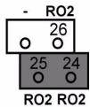
| 24 | RO 21 | Relay out 2 | Active = FAULT P) | Max. switching load: 250Vac/2A or 250Vdc/0.4A |
| 25 | RO 22 | |||
| 26 | RO 23 | |||
SmartDrive Compact I/O terminals:
4. NAVIGATION & STARTUP
4.1 THE MAIN MENU OF SMARTDRIVE COMPACT
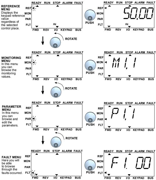
Figure 1: The main menu of SmartDrive Compact
4.2 COMMISSIONING AND STARTUP WIZARD
4.2.1 Commissioning steps
Table 1: Commissioning steps
| 1. Read safety instructions on page 1 | 6. Run the Startup wizard and set all necessary parameters |
| 2. Secure the grounding and check that cables comply with requirements | 7. Perform test run without motor, see the User Manual: http://ecc.emea.honeywell.com |
| 3. Check quality and quantity of cooling air | 8. Run no-load tests without motor being connected to the process |
| 4. Check that all start/stop switches are in STOP position | 9. Connect the motor to the process and perform test run once again |
| 5. Connect the drive to mains | 10. SmartDrive Compact is now ready for use |
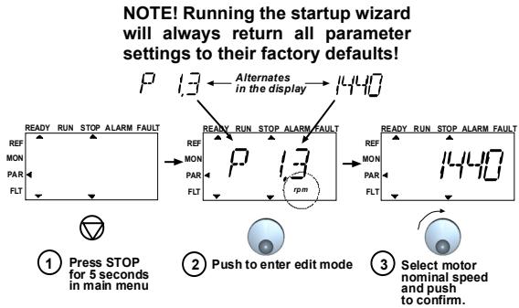
4.2.2 Startup wizard
SmartDrive Compact runs the startup wizard in first power-up. After that the wizard can be run by pressing STOP for 5 seconds in main menu. The following figures show the procedure.
PERFORM THE SAME PROCEDURE FOR PAR.1.4, MOTOR NOMINAL CURRENT
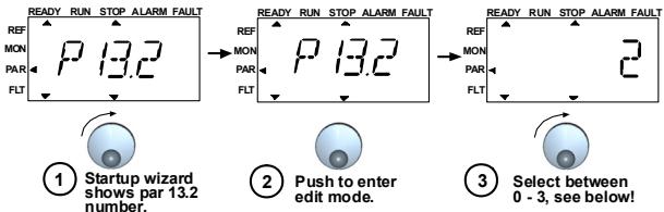
PERFORM DRIVE SETUP, PAR. 13.2, SEE NEXT PAGE
Figure 2: SmartDrive Compact startup wizard
Selections:
| P1.1 | P1.2 | P1.7 | P1.15 | P2.1 | P2.2 | P2.3 | P3.1 | P3.2 | P3.3 | P4.2 | P4.3 | |
| 0 = Basic | 400V* | 50Hz | 1,1*INMOT | 0=Not used | I/O | 0=Ramp | 0=Coast | 0Hz | 50Hz | 0=A10-10V | 3s | 3s |
| 1 = Pump drive | 400V* | 50Hz | 1,1*INMOT | 0=Not used | I/O | 0=Ramp | 1=Ramp | 20Hz | 50Hz | 0=A10-10V | 5s | 5s |
| 2 = Fans | 400V* | 50Hz | 1,1*INMOT | 0=Not used | I/O | 0=Ramp | 0=Coast | 20Hz | 50Hz | 0=A10-10V | 20s | 20s |
| 3 = Conveyor drive | 400V* | 50Hz | 1,5*INMOT | 1=Used | I/O | 0=Ramp | 0=Coast | 0Hz | 50Hz | 0=A10-10V | 1s | 1s |
| *In drives of 208V,this value is 230V | ||||||||||||
Parameters affected:
| P1.1 Motor Un (V) | P2.3 Stop function |
| P1.2 Motor fn (Hz) | P3.1 Min frequency |
| P1.7 Current limit (A) | P3.2 Max frequency |
| P1.15 Torque boost | P3.3 I/O reference |
| P2.1 Control place | P4.2 Acc. time (s) |
| P2.2 Start function | P4.3 Dec time (s) |
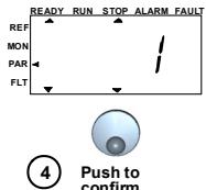
Figure 3: Drive setup
4.2.3 Manual testing
1. Hold NAVIGATION WHEEL down for 5 seconds
Control Place automatically switches to manual control
2. Use the buttons for speed control
START and STOP for control
- Move to reference menu REF
- NAVIGATION WHEEL for adjusting the speed
- Hold NAVIGATION WHEEL down for 5 seconds to return to remote control (I/O or fieldbus)
5. MONITORING & PARAMETERS
Note! Complete parameter listing and descriptions are given in SmartDrive Compact User Manual, available on the CD delivered with the product and downloadable at: http://ecc.emea.honeywell.com/inverter
5.1 MONITORING VALUES
Table 1: SmartDrive Compact monitoring values (Complete parameter list and parameter descriptions can be found from Complete SmartDrive Compact User Manual available on product CD or at: http://ecc.emea.honeywell.com/inverter)
| Code | Monitoring signal | Unit | ID | Description |
| M1.1 | Output frequency | Hz | 1 | Frequency to the motor |
| M1.2 | Frequency reference | Hz | 25 | |
| M1.3 | Motor shaft speed | rpm | 2 | Calculated motor speed |
| M1.4 | Motor current | A | 3 | Measured motor current |
| M1.5 | Motor torque | % | 4 | Calculated actual/nominal torque of the motor |
| M1.6 | Motor power | % | 5 | Calculated actual/nominal power of the motor |
| M1.7 | Motor voltage | V | 6 | Motor voltage |
| M1.8 | DC-link voltage | V | 7 | Measured DC-link voltage |
| M1.9 | Unit temperature | °C | 8 | Heat sink temperature |
| M1.10 | Motor temperature | °C | Calculated motor temperature | |
| M1.11 | Analogue input 1 | % | 13 | AI1 value |
| M1.12 | Analogue input 2 | % | 14 | AI2 value |
| M1.13 | Analogue output | % | 26 | AO1 |
| M1.14 | DI1, DI2, DI3 | 15 | Digital input statuses | |
| M1.15 | DI4, DI5, DI6 | 16 | Digital input statuses | |
| M1.16 | RO1, RO2, DO | 17 | Relay/digital output statuses | |
| M1.17 | PI setpoint | % | 20 | In percent of the maximum process reference |
| M1.18 | PI feedback | % | 21 | In percent of the maximum actual value |
| M1.19 | PI error value | % | 22 | In percent of the maximum error value |
| M1.20 | PI Output | % | 23 | In percent of the maximum output value |
5.2 QUICK SETUP PARAMETERS
| Code | Parameter | Min | Max | Unit | Default | ID | Note |
| P1.1 | Motor nominal voltage | 180 | 500 | V | 230 400 | 110 | Check rating plate on the motor |
| P1.2 | Motor nom. fre- quency | 30 | 320 | Hz | 50,00 | 111 | Check rating plate on the motor |
| P1.3 | Motor nominal speed | 300 | 2000 0 | rpm | 1440 | 112 | Default applies for a 4-pole motor. |
| P1.4 | Motor nominal current | 0,2 x INunit | 1,5 x INunit | A | INunit | 113 | Check rating plate on the motor |
| P1.5 | Motor cos (f) | 0,30 | 1,00 | 0,85 | 120 | Check rating plate on the motor | |
| P1.7 | Current limit | 0,2 x INunit | 2 x INunit | A | 1,5 x INunit | 107 | |
| P1.15 | Torque boost | 0 | 1 | 0 | 109 | 0 = Not used 1 = Used | |
| P2.1 | Control place | 1 | 3 | 1 | 125 | 1 = I/O termina 2 = Keypad 3 = Fieldbus | |
| P2.2 | Start function | 0 | 1 | 0 | 505 | 0 = Ramp 1 = Flying start | |
| P2.3 | Stop function | 0 | 1 | 0 | 506 | 0 = Coasting 1 = Ramp | |
| P3.1 | Min frequency | 0,00 | P3.2 | Hz | 0,00 | 101 | |
| P3.2 | Max frequency | P3.1 | 320 | Hz | 50,00 | 102 | |
| P3.3 | I/O reference | 0 | 4 | 3 | 117 | 0 = Preset Speeds (0-7) 1 = Keypad Reference 2 = Fieldbus Reference | |
| 3 = AI1 | |||||||
| 4 = AI2 | |||||||
| P3.4 | Preset speed 0 | 0,00 | P3.2 | Hz | 5,00 | 124 | Activated by digital inputs |
| P3.5 | Preset speed 1 | 0,00 | P3.2 | Hz | 10,00 | 105 | Activated by digital inputs |
| P3.6 | Preset speed 2 | 0,00 | P3.2 | Hz | 15,00 | 106 | Activated by digital inputs |
| P3.7 | Preset speed 3 | 0,00 | P3.2 | Hz | 20,00 | 126 | Activated by digital inputs |
Table 2: Quick setup parameters (Complete parameter list and parameter descriptions can be found from Complete SmartDrive Compact User Manual available on product CD or at: http://ecc.emea.honeywell.com/inverter)
Table 2: Quick setup parameters (Complete parameter list and parameter descriptions can be found from Complete SmartDrive Compact User Manual available on product CD or at: http://ecc.emea.honeywell.com/inverter)
| Code | Parameter | Min | Max | Unit | Default | ID | Note |
| P4.2 | Acceleration time | 0,1 | 3000 | s | 1,0 | 103 | |
| P4.3 | Deceleration time | 0,1 | 3000 | s | 1,0 | 104 | |
| P6.1 | AI1 Signal range | 0 | 3 | 0 | 379 | 0 = Voltage 0...10 V 1 = Voltage 2...10 V | |
| P6.5 | AI2 Signal range | 2 | 3 | 3 | 390 | 2 = Current 0...20 mA 3 = Current 4...20 mA | |
| P10.4 | Automatic restart | 0 | 1 | 0 | 731 | 0 = Not used 1 = Used | |
| P13.1 | Parameter conceal | 0 | 1 | 1 | 115 | 0 = All parameters visible 1 = Only quick setup parameters visible |
5.3 SYSTEM MENU PARAMETERS
Table 3: System menu parameters
| Code | Parameter | Min | Max | Default | Note |
| Software information (MENUPAR→S1) | |||||
| S1.1 | Software package | ||||
| S1.2 | Power SW version | ||||
| S1.3 | SW version | ||||
| S1.4 | Firmware interface | ||||
| S1.5 | Application ID | ||||
| S1.6 | Application revision | ||||
| S1.7 | System load | ||||
| RS485 information (MENUPAR→S2) | |||||
| S2.1 | Communication status | Format: xx.yyy xx = 0 - 64 (Number of error messages) yyy = 0 - 999 (Number of good messages) | |||
| S2.2 | Fieldbus protocol | 0 | 1 | 0 | 0 = FB disabled 1= Modbus |
| S2.3 | Slave address | 1 | 255 | ||
| S2.4 | Baud rate | 0 | 5 | 5 | 0=300, 1=600, 2=1200, 3=2400, 4=4800, 5=9600, |
| S2.5 | Number of stop bits | 0 | 1 | 1 | 0=1, 1=2 |
| S2.6 | Parity type | 0 | 0 | 0 | 0= None (locked) |
| S2.7 | Communication time-out | 0 | 255 | 0 | 0= Not used, 1= 1 second, 2= 2 seconds, etc. |
| S2.8 | Reset communication status | 1= Resets par. S2.1 | |||
| Total counters (MENUPAR→S3) | |||||
| S3.1 | MWh counter | 0 | 1 | 0 | |
| S3.2 | Power on days | 0 | 1 | 0 | |
| S3.3 | Power on hours | 0 | 1 | 0 | |
| User settings (MENUPAR→S4) | |||||
| S4.1 | Display contrast | 0 | 15 | 7 | Adjusts the display contrast |
| S4.2 | Restore factory defaults | 0 | 1 | 0 | 1= Restores factory defaults |
- FAULT TRACING
| Fault code | Fault name | Quick corrective actions |
| 1 | Overcurrent | - Check loading. - Check cables. - Check motor size. |
| 2 | Overvoltage | Increase deceleration time (P4.3). |
| 3 | Earth fault | - Check motor Cables- Check motor. |
| 8 | System fault | Reset the fault and restart. Should the fault recur, contact the technical support. |
| 9 | Undervoltage | In case of temporary supply voltage break, reset the fault and restart. Check supply voltage. |
| 13 | Inverter under temperature | Check that the product is operated in specified conditions. |
| 14 | Inverter over temperature | - Check that the cooling air is not blocked. - Check the ambient temperature. - Make sure that the switching frequency is not too high in relation to ambient temperature and motor load (P1.16). |
| 15 | Motor stalled | - Check motor - Check that the pump or fan is not blocked. |
| 16 | Motor overtemperature | - Check that motor parameters are cor rect (P1.1-P1.5). - Decrease motor load. |
| 17 | Motor Underload | FAN: check that belt is not broken. PUMP: check that pump is not dry. |
| 22 | EEPROM checksum fault | Reset the fault and restart. Should the fault recur, contact the technical support. |
| 25 | Microcontroller watchdog fault | Reset the fault and restart. Should the fault recur, contact the technical support. |
| 34 | Internal bus communication | Reset the fault and restart. Should the fault recur, contact the technical support. |
| 35 | Application fault | Reset the fault and restart. Should the fault recur, contact the technical support. |
Table 1: Fault codes. See User Manual for detailed fault descriptions
| Fault code | Fault name | Quick corrective actions |
| 50 | Analogue input lin < 4mA (selected signal range 4 to 20 mA) | Check the control cabling |
| 53 | Fieldbus fault | - Check installation. - If installation is correct contact technical support |
- GENERAL DATA
| Dimensions and weight | Frame | Height | Width | Depth (mm) | Weight (kg) |
| MI1 | 156,5 | 65,5 | 98,5 | 0,55 | |
| MI2 | 195 | 90 | 101,5 | 0,70 | |
| MI3 | 262,5 | 100 | 108,5 | 0,99 | |
| Supply network | SmartDrive Compact cannot be used with corner grounded networks | ||||
| Motor connection | Output voltage | 0 - Uin | |||
| Output current | Continuous rated current IN at ambient tempera-ture max. +50°C, overload 1.5 x IN max. 1min/10min | ||||
| Ambient conditions | Ambient operating temperature | -10°C (no frost)...+50°C: rated loadability IN | |||
| Storage temperature | -40°C...+70°C | ||||
| Enclosure class | IP20 | ||||
| Relative humidity | 0...95% RH, non-condensing, non-corrosive, no dripping water | ||||
| Altitude | 100% load capacity (no derating) up to 1000m. 1% derating for each 100m above 1000m; max. 2000m | ||||
| EMC | Immunity | Complies with EN50082-1, -2, EN61800-3 | |||
| Emissions | Complies as standard with EN6 1800-3 Cate-gory C2 (Honeywell level H: normal public elec-tricity network requirements). Category C1 with external EMC-filter (Honeywell level C: special requirements for sensitive areas installations). | ||||
| Standards | For EMC: EN61800-3, For safety: UL508C, EN61800-5-1 | ||||
| Certificates and manufacturer's declarations of conformity | For safety: CB, CE, UL, cUL, For EMC: CE, CB, c-tick (see unit nameplate for more detailed approvals) | ||||
| Cable and fuse requirements380 - 500V | Frame | Fuse(A) | Mains cableCu (mm2) | Terminal cable min-max (mm2) | |
| Main & earth | Control & relay | ||||
| MI1 | 6 | 3*1.5+1.5 | 1.5-4 | 0.5-1.5 | |
| MI2 | 10 | ||||
| MI3 | 20 | 3*2.5+2.5 | 1.5-6 | ||
| 208 - 240V | MI1 | 10 | 2*1.5+1.5 | 1.5-4 | |
| MI2 | 20 | 2*2.5+2.5 | |||
| MI3 | 32 | 2*6+6 | 1.5-6 | ||
- With above-mentioned fuses, the drive can be connected to power supply the short circuit current of which is max. 50kA
- Use cables with heat resistance of at least +70C
- The fuses function also as cable overload protection.
- These instructions apply only to cases with one motor and one cable connection from the inverter to the motor.
- To fulfil standard EN61800-5-1, the protective conductor should be at least 10mm2 Cu or 16mm Al. Another possibility is to use an additional protective conductor of at least the same size as the original one.
SmartDrive Compact power ratings
| Mains voltage 208-240 V, 50/60 Hz, 1~ series | |||||
| Product code | Rated loadability | Motor shaft power | Nominal input current | Mechanical size | |
| 100% contin. current IN [A] | 150% overload current [A] | P [kW] | [A] | ||
| COMP230-P25-20 | 1,7 | 2,6 | 0,25 | 4,2 | MI1 |
| COMP230-P37-20 | 2,4 | 3,6 | 0,37 | 5,7 | MI1 |
| COMP230-P55-20 | 2,8 | 4,2 | 0,55 | 6,6 | MI1 |
| COMP230-P75-20 | 3,7 | 5,6 | 0,75 | 8,3 | MI1 |
| COMP230-1P1-20 | 4,8 | 7,2 | 1,1 | 11,2 | MI2 |
| COMP230-1P5-20 | 7,0 | 10,5 | 1,5 | 14,1 | MI2 |
| COMP230-2P2-20 | 9,6 | 14,4 | 2,2 | 15,8 | MI3 |
| Mains voltage 380-480 V, 50/60 Hz, 3~ series | |||||
| Product code | Rated loadability | Motor shaft power | Nominal input current | Mechanical size | |
| 100% continuous current IN [A] | 150% over-load current [A] | 380-480V supply P[kW] | [A] | ||
| COMP400-P37-20 | 1,3 | 2,0 | 0,37 | 2,2 | MI1 |
| COMP400-P55-20 | 1,9 | 2,9 | 0,55 | 2,8 | MI1 |
| COMP400-P75-20 | 2,4 | 3,6 | 0,75 | 3,2 | MI1 |
| COMP400-1P1-20 | 3,3 | 5,0 | 1,1 | 4,0 | MI1 |
| COMP400-1P5-20 | 4,3 | 6,5 | 1,5 | 5,6 | MI2 |
| COMP400-2P2-20 | 5,6 | 8,4 | 2,2 | 7,3 | MI2 |
| COMP400-3P0-20 | 7,6 | 11,4 | 3,0 | 9,6 | MI3 |
| COMP400-4P0-20 | 9,0 | 13,5 | 4,0 | 11,5 | MI3 |
| COMP400-5P5-20 | 12,0 | 18,0 | 5,5 | 14,9 | MI3 |
Note: The input currents are calculated values with 100kVA line transformer supply.
Index
- SICHERHEIT 23
- INSTALLATION 25
For more information on Honeywell's frequency converters and other Honeywell products, visit us online at http://ecc.emea.honeywell.com
Automation and Control Solutions
Honeywell GmbH
Böblinger Str. 17
71101 Schonaich, Germany
Telephone (49) 7031 637 01
Telefax (49) 7073 637 493
www.ecc.emea.honeywell.com
MU1B-0431GE51 R0209
February 2009
© 2009 Honeywell International Inc.
- SAFETY
- ONLY A COMPETENT ELECTRICIAN IS ALLOWED TO CARRY OUT THE ELECTRICAL INSTALLATION
- Please read these warnings carefully:
- See Chapter 7!
- INSTALLATION
- MECHANICAL INSTALLATION
- CABLING AND CONNECTIONS
- Power cabling
- Control cabling
- CONTROL I/O AND TERMINALS
- NAVIGATION & STARTUP
- THE MAIN MENU OF SMARTDRIVE COMPACT
- COMMISSIONING AND STARTUP WIZARD
- Commissioning steps
- Startup wizard
- Manual testing
- Hold NAVIGATION WHEEL down for 5 seconds
- Use the buttons for speed control
- MONITORING & PARAMETERS
- MONITORING VALUES
- QUICK SETUP PARAMETERS
- SYSTEM MENU PARAMETERS
- Index
Brand : HONEYWELL
Model : SMARTDRIVE COMPACT
Category : Fleet Management System