
PW50CS - Water Softener HONEYWELL - Free user manual and instructions
Find the device manual for free PW50CS HONEYWELL in PDF.
| Product type | Water softener |
| Model | PW50-CS |
| Resin volume | 20 litres |
| Nominal flow rate (Δp=1.0 bar) | 1.4 m³/h |
| Nominal flow rate (Δp=1.8 bar) | 1.8 m³/h |
| Max. backwash (p=1.8 bar) | 1.6 m³/h |
| Power supply | External 24 V transformer (low voltage), 2 W |
| Protection class | IP 22 |
| Operating pressure | 2.0 - 8.0 bars |
| Water temperature | 5 - 30 °C |
| Ambient temperature | 2 - 40 °C |
| Regeneration duration (PW50-CS) | Approximately 102 minutes |
| Salt consumption per regeneration (PW50-CS) | Approximately 102 liters of regeneration water |
| Main functions | Ion exchange softening, automatic regeneration, integrated bypass, residual hardness adjustment, digital display, timed or forced regeneration |
| Maintenance | Check salt level (min. 10 cm) weekly; clean every 6 months; annual maintenance by professional |
| Spare parts | Honeywell maintenance kits available; parts: control valve, flow meter, resin, etc. |
| Safety | Observe max. pressure 8 bar; max. temperature 30°C; do not use solvents; bypass in case of malfunction |
Frequently Asked Questions - PW50CS HONEYWELL
User questions about PW50CS HONEYWELL
0 question about this device. Answer the ones you know or ask your own.
Ask a new question about this device
Download the instructions for your Water Softener in PDF format for free! Find your manual PW50CS - HONEYWELL and take your electronic device back in hand. On this page are published all the documents necessary for the use of your device. PW50CS by HONEYWELL.
USER MANUAL PW50CS HONEYWELL
Keep instructions for later use!
- Follow the installation instructions.
- Use the appliance
according to its intended use
in good condition
with due regard to safety and risk of danger. - Note that the appliance is exclusively for use in the applications detailed in these installation instructions. Any other use will not be considered to comply with requirements and would invalidate the warranty.
- Please take note that any assembly, commissioning, servicing and adjustment work may only be carried out by authorized persons.
- Immediately rectify any malfunctions which may influence safety.
2. Functional description
Hard or medium-hard drinking water contains large amounts of lime, which can deposit in pipes, fittings and devices and result in irreparable damages.
KaltecSoft is based on the simple exchange of minerals. Calcium and magnesium is replaced by sodium, thus preventing additional scale build up.
3. Application
Medium Water
Water temperature 5-30°C
Operating pressure 2,0-8,0 bar
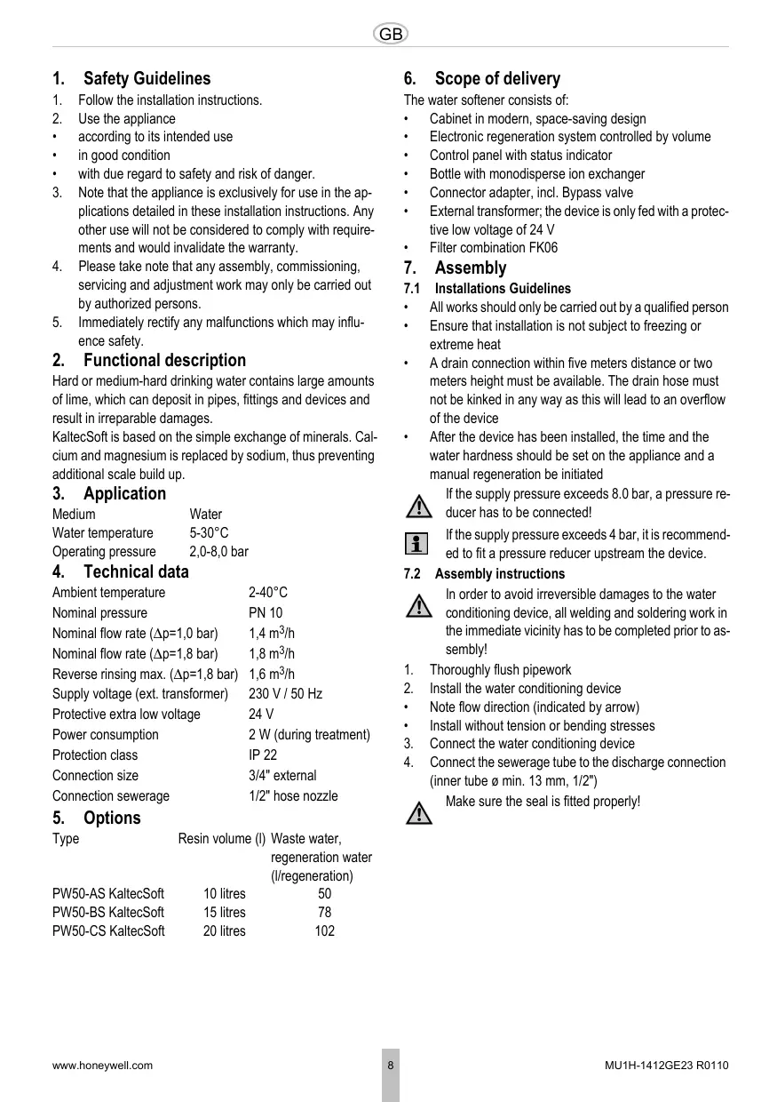
4. Technical data
Ambient temperature 2-40°C
Nominal pressure PN 10
Nominal flow rate ( p = 1,0 bar) 1,4m^3 /h
Nominal flow rate ( p = 1,8 bar) 1,8m^3 /h
Reverse rinsing max. ( p = 1,8 bar) 1,6m^3 /h
Supply voltage (ext. transformer) 230V / 50Hz
Protective extra low voltage 24 V
Power consumption 2 W (during treatment)
Protection class IP 22
Connection size 3/4" external
Connection sewerage 1/2" hose nozzle
5. Options
| Type | Resin volume (l) | Waste water, regeneration water (l/regeneration) |
| PW50-AS KaltecSoft | 10 litres | 50 |
| PW50-BS KaltecSoft | 15 litres | 78 |
| PW50-CS KaltecSoft | 20 litres | 102 |
6. Scope of delivery
The water softener consists of:
Cabinet in modern, space-saving design
Electronic regeneration system controlled by volume
Control panel with status indicator
- Bottle with monodisperse ion exchanger
- Connector adapter, incl. Bypass valve
External transformer; the device is only fed with a protective low voltage of 24V
Filter combination FK06
7. Assembly
7.1 Installations Guidelines
All works should only be carried out by a qualified person
- Ensure that installation is not subject to freezing or extreme heat
- A drain connection within five meters distance or two meters height must be available. The drain hose must not be kinked in any way as this will lead to an overflow of the device
After the device has been installed, the time and the water hardness should be set on the appliance and a manual regeneration be initiated
If the supply pressure exceeds 8.0 bar, a pressure reducer has to be connected!
If the supply pressure exceeds 4 bar, it is recommended to fit a pressure reducer upstream the device.
7.2 Assembly instructions
In order to avoid irreversible damages to the water conditioning device, all welding and soldering work in the immediate vicinity has to be completed prior to assembly!
- Thoroughly flush pipework
- Install the water conditioning device
Note flow direction (indicated by arrow)
Install without tension or bending stresses - Connect the water conditioning device
- Connect the sewerage tube to the discharge connection (inner tube min. 13mm 1 / 2^ )

Make sure the seal is fitted properly!
8. Commissioning

Commissioning has to take place in the following order!
8.1 Flush and Deaerate
- Set the water conditioning device to "Bypass" (handles to position cross)
- Open the main water supply
- Open the nearest cold water tap and allow the water to run. Impurities and soldering remains are flushed out of the pipework
- Set the water conditioning device to "Service" (handles to position straight)
- Deaerate the water conditioning device, flush device for approx. 10 minutes
- Should the bypass unit be dripping, open and close again
- Close the cold water tap

Noise development can occur during regeneration due to incompletedeaerating.However,this will disappear after 2-3 regenerations!
8.2 Cabinet
- Remove covering cap and salt lid. The brine tube remains closed
- Manually fill water into the cabinet The water level should be approx. 3 cm
- Fill up the cabinet with a bag of block salt for softeners (according to DIN EN 973)

Wait until the brine formation is sufficient (1h - 12h)!
8.3 Time Setting
- Connect the mains plug to the power supply o The power supply has to conduct continuous operat ing voltage and should not be connected to a switch
- Set the time via the 和 and 和 buttons o The clock runs quicker when the 和 and 和 but-tons are held pressed
8.4 Determining Water Hardness

The raw water hardness can be requested from the responsible waterworks or determined via a hardness measuring instrument in the main water supply in front of the water conditioning device.
- Set the water conditioning device to "Bypass" (handles to position cross)
- Take a water sample at the first draw-off station
- Determine the water hardness via a hardness measuring instrument
- Set the water conditioning device to "Service" (handles to position straight)
8.5 Blending Setting
The desired residual hardness (mixing ratio between raw water and soft water) has to be set at the blending

It is recommended that drinking water keeps a residual hardness of 1.0 mmol/l (equals 100 ppm CaCO3 or 6^ ! The sodium content of the softened drinking water increases by 0.46mg / l per ppm removed hardness (by 46 mg/l per mmol/l removed hardness), and must not exceed the limit value of 200 mg/l!
- Open sampling point
- Remove cover from adjustment knob
- Set blending
o Turn adjuster knob until the desired hardness is reached (recommended: 100 ppm)
o Do not turn in too far!

Position "max"
Position "closed"


In position "closed" no untreated water added to the soft water!
- Fit cover to adjustment knob
- Close sampling point
- The water conditioning device is ready for operation
8.6 Calculating the Set Value for capacity
A value for the capacity has to be set at the water conditioning device according to the water hardness, and is calculated as follows:
Set value = Factor F: (Raw water - Residual Hardness)

Factor F + Figure 8.6
Example 1:
Water conditioning device PW50-AS
Factor F for ^ unit 28.000
Raw water hardness 24°dH
set residual hardness 8° dH
Set value = 28.000 : (24-8)
Set value = 1.750
Example 2:
Water conditioning device PW50-BS
Factor F for ^ unit 42.000
Raw water hardness 19°dH
set residual hardness 5^
Set value = 42.000 : (19-5)
Set value = 3.000
8.7 Capacity Setting
- Simultaneously press the 和 and 和 buttons for 5 seconds

If p -2 is displayed, press no further buttons (test mode manufacturer)!
Wait for approx. 10 seconds until the current time is redisplayed!
- Enter the calculated set value via the 和 and 和 buttons
- Press the button three times to save the setting
9. Operation
9.1 Control Buttons, Display and Indicators
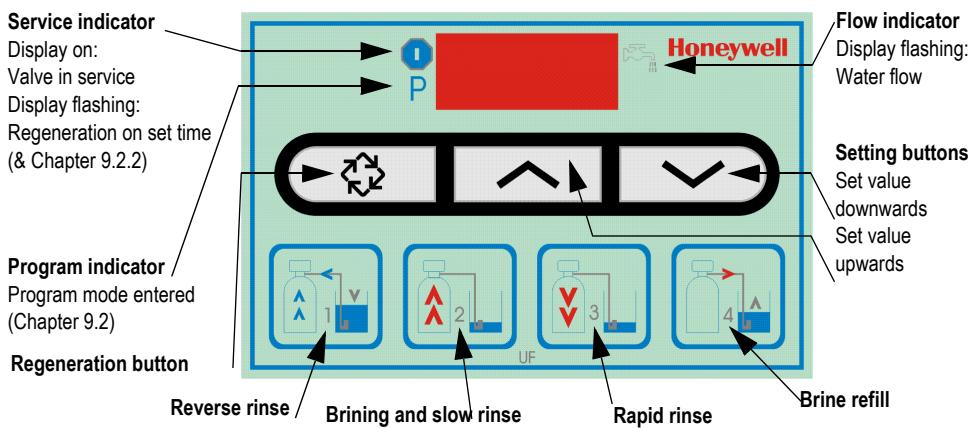
9.2 Display during Operation
During normal operation the time and residual capacity are displayed alternately
Time
Residual volume (litre)


9.3 Display during Regeneration
During regeneration the active regeneration phase is displayed. In addition to the phase number the remaining time of the active regeneration phase is also displayed. After all 4 regeneration phases have been completed, the water conditioning device returns to normal operation
Regeneration Phase 2, Remaining time 27 Minutes

9.4 "Bypass" function
9.4.1"Bypass" position
In this position the raw water is not softened
The raw water runs, via the bypass valve, through the connection adaptor back into the drinking water supply
9.4.2"Service" position
In this position the raw water is softened and blended with hard water as to the setting of the blending adjuster
9.4.3Start-Up operation
For the first 1-2 week running period the brand-new water conditioning device is in start-up operation
During this period noise development can occur during regeneration but will automatically disappear after approx. 1-2 weeks
8.8 Manual Regeneration
Press the button 5 seconds
Manual regeneration starts immediately
Flushing takes place via the drain tube during regeneration!
The total time required for all 4 regeneration phases is:
approx. 52 min/PW50-AS
approx. 77 min/PW50-BS
approx. 102 min/PW50-CS
10. Settings
10.1 Time

Input: 24-hour mode
- Set the time via the 和 and 和 buttons o The clock runs quicker when the 和 and 和 but-tons are held pressed
Time

10.2 Control valve

All settings at the control valve have to be entered in the check list!

Incorrect parameter changes can lead to substantial property damages!

In order to accept changes for the control valve settings, run the programming until the end. Proceed with the button!
10.2.1 Capacity setting
- Simultaneously press the and buttons for 5 seconds

If p = -2 is displayed, press no further buttons (test mode manufacturer)!
Wait for approx. 10 seconds until the current time is redisplayed!
- Enter the calculated set value via the but-tons
- Press the button once to go to the next setting

In operation or water consumption the residual capacity is reduced from the set amount to zero.
Residual volume 530 litres
Residual volume 0 litres


10.2.2Time-delayed, volume-controlled regeneration
Regeneration is triggered at the set time if the remaining capacity does not suffice for the next full day

Set to 02:00 a.m. at the factory!
Input: 24-hour mode
Time regeneration

- Press the × and buttons to change the time
- Press the button once to go to the next setting
10.2.3Forced regeneration

If the programmed number of days between two regenerations has been reached, a forced regeneration is triggered at the set time. The forced regeneration is triggered irrespective of the residual volume. Set to 7 days at the factory!
Input: OFF up to 99 days
Forced regeneration

- Press the × and buttons to change the number of days
- Press the button once to accept all the changes
10.3 Manual Regeneration
There are two manual regeneration possibilities available
- Possibility
Press the button 5 seconds
Manual regeneration starts immediately
- Possibility
Briefly press the key
Manual regeneration starts at the set time

Operating display flashes
10.3.1 Change to the next regeneration phase
- Press the button once to go to the next regeneration phase If the water conditioning device is in between two phases (phase display flashes), pressing the button has no effect
11. Power Failure
11.1 Settings
The time has to be reentered after a power failure (Chapter 10.1)
All the control valve settings remain and are restored once the power supply has been reconnected
11.2 General Information
After the power supply has been reconnected, it is recommended to start a manual regeneration (Chapter 10.3)
12. Maintenance
12.1 Block Salt Level

To be checked frequently (e.g. weekly).
- Remove the covering cap from the cabinet
- Remove the salt lid from the cabinet
- Check the level in the cabinet
- If the salt level has fallen below 10cm Refill block salt (Chapter 8.2)
- Attach the salt lid
- Replace the covering cap on the cabinet
12.2 Maintenance
According to European and national standards, regular maintenance measures must be taken. Honeywell provides suitable maintenance kits

Maintenance work should only be carried out be qualified staff!

Device for single-family houses interval: annually

Device for apartment blocks, public institutions interval: every 6 months
12.3 Cleaning

Interval: every 6 months (depending on local conditions)
To be carried out by an installation company
To be carried out by the operator

Do not use cleaning agents that contain solvents when cleaning the plastic parts!

Detergents must not be allowed to enter the environment or the sewerage system!
- Set the water conditioning device to "Bypass" (handles to position cross)
- Remove the covering cap from the cabinet
- Remove the salt lid from the cabinet
- Check the inner and outer brine tube for contamination and salt deposits
- Clean the inner and outer parts with water and a cloth
- Check the inner and outer cabinet for contamination and salt deposits
- Clean the inner and outer parts with water and a cloth
- Attach the salt lid
- Replace the covering cap on the cabinet
- Set the water conditioning device to "Service" (handles to position straight)
13. Disposal
Cabinet made of high-quality plastic material
- All components subject to pressure in glass-fibre-reinforced plastics
All components to brine in Noryl

Observe the local requirements regarding correct waste recycling/disposal!
14. Troubleshooting
| Problem | Cause | Remedy |
| No water supply to the device | Shut-off device in the bypass is not open or only partially open | Open shut off valve fully |
| Pipework of the drinking water supply is calcified or blocked | Clean or replace the pipework | |
| Device does not regenerate | Flow meter is defective | Check and, if necessary, replace the flow meter (CS*) |
| Incorrect settings at the control valve | Check the control valve settings | |
| Water meter is contaminated or defective | Clean and, if necessary, replace water meter (CS*) | |
| Internal electric cabling is defective | Check internal electric cabling (CS*) | |
| Call Technical Customer Service | ||
| Wrong connection of connecting hoses | Connect the flexible connection lines correctly | |
| Control head is defective | Call Technical Customer Service | |
| Nothing is displayed | Power supply has been interrupted | Check power supply (mains plug, fuse) |
| Control head is defective | Call Technical Customer Service | |
| Incorrect time is displayed | Power failure occurred | Set the time |
| Tank overflows | Internal pipework is contaminated or leaking | Check pipework (CS*) |
| Float valve is defective | Check float valve (CS*) | |
| Insufficient function | Device not deaerated | Deaerate device |
| Device is in "Bypass" position | Set device to "Service" position | |
| Incorrect settings at the control valve | Check the control valve settings | |
| Storage tank is almost or completely empty | Check salt level | |
| Wrong block salt | Use block salt for softeners DIN EN 973 | |
| Blending has been set incorrectly | Check blending valve and mixing ratio | |
| Control valve is contaminated or defective | Clean control valve or, if necessary, replace control head (CS*) | |
| Check the control valve settings | ||
| Permanent regeneration | Control head is defective | Call Technical Customer Service |
| Incorrect settings at the control valve | Check the control valve settings | |
| No brine intake | Incorrect settings at the control valve | Check the control valve settings |
| Brine tube is leaking | Replace brine tube | |
| Drain tube is blocked | Clean and, if necessary, replace drain tube | |
| Min. operating pressure not available | Min. operating pressure is 2.0 bar | |
| Permanent discharge into sewerage tube | Back pressure in drain tube is too high | Clean and, if necessary, replace sewerage tube |
| Control head is defective | Call Technical Customer Service | |
| High salt consumption | Incorrect settings at the control valve | Check the control valve settings |
| Blending has been set incorrectly | Check blending valve and mixing ratio | |
| Too much water in the storage tank | Fault "too much water in the storage tank" | |
| No or insufficient salt consumption | Incorrect settings at the control valve | Check the control valve settings |
| Blending has been set incorrectly | Check blending valve and mixing ratio | |
| Brine tube is contaminated | Clean brine tube | |
| Bypass is closed | Open Bypass | |
| Saline water | Min. operating pressure not available | Min. operating pressure is 2.0 bar |
| Incorrect settings at the control valve | Check the control valve settings | |
| Brine valve is contaminated or defective | Clean and, if necessary, replace brine valve (CS*) | |
| Control head is defective | Call Technical Customer Service | |
| Differential pressure at the device is too high | Construction of the device is too small | Call Technical Customer Service |
| Blending has been closed too widely | Check blending and mixing ratio | |
| Water pressure reduction / slowly decreasing effectiveness | Pipework of the drinking water supply is calcified or blocked | Clean or replace the pipework |
| Control valve is contaminated or defective | Clean control valve or, if necessary, replace control head (CS*) | |
| Water meter is contaminated or defective | Clean and, if necessary, replace water meter (CS*) | |
| Increasing iron deposit in the resin | Exchange resin (CS*) | |
| Too much water in the storage tank | Brine tube is contaminated | Clean brine tube |
| Drain tube is blocked | Clean and, if necessary, replace drain tube | |
| Incorrect settings at the control valve | Check the control valve settings | |
| Brine valve is contaminated or defective | Clean and, if necessary, replace brine valve (CS*) |
*CS = Customer Service
Dim. raccord 3/4" AG
Raccordement effluents Embout a olive 1/2"
5. Variantes
9.4.1 Position "by-pass"
9.4.2 Position "service"
Automation and Control Solutions
Honeywell GmbH
Hardhofweg
D-74821 Mosbach
Phone: (49) 6261 810
Fax: (49) 6261 81309
http://europe.hbc.honeywell.com
www.honeywell.com
Manufactured for and on behalf of the
Environmental and Combustion Controls Division of
Honeywell Technologies Sàrl, Z.A. La Pièce 16,
1180 Rolle, Switzerland by its Authorised Representative Honeywell GmbH
MU1H-1412GE23 R0110
Subject to change
1 Safety Guidelines 8
2 Functional description 8
3 Application 8
4 Technical data 8
5 Options 8
6 Scope of delivery 8
7 Assembly 8
8 Commissioning 9
9 Operation 10
10 Settings 11
11 Power Failure 11
12 Maintenance 11
13 Disposal 12
14 Troubleshooting 12