
VPL-AW15S - Projector SONY - Free user manual and instructions
Find the device manual for free VPL-AW15S SONY in PDF.


| Product type | Home cinema video projector |
| Brand | Sony |
| Model | VPL-AW15S |
| Projection technology | 3LCD |
| Native resolution | 1280 x 720 pixels (HD Ready) |
| Brightness | 1200 ANSI lumens |
| Contrast ratio | 12000:1 (dynamic contrast) |
| Lamp type | 200 W UHP lamp |
| Lamp life | Up to 3000 hours in standard mode |
| Aspect ratio | 16:9 native |
| Zoom lens | 1.6x manual zoom with focus |
| Lens shift | Vertical lens shift |
| Video inputs | HDMI, component, S-Video, composite, RGB/PC, RS-232C |
| Power consumption | 265 W maximum, less than 0.5 W in standby |
| Dimensions (W x H x D) | Approximately 450 x 140 x 360 mm |
| Weight | Approximately 6.5 kg |
| Noise level | Up to 32 dB in standard mode, lower in Eco mode |
| Image size | 40 to 300 inches diagonal |
| Keystone correction | Vertical keystone correction |
| Security | Kensington lock slot and overheating protection |
| Maintenance and cleaning | Clean the air filter periodically in dusty environments |
| Spare parts and repairability | User-replaceable lamp module and air filter |
| General information | Complies with CE and RoHS directives |
Frequently Asked Questions - VPL-AW15S SONY
User questions about VPL-AW15S SONY
0 question about this device. Answer the ones you know or ask your own.
Ask a new question about this device
Download the instructions for your Projector in PDF format for free! Find your manual VPL-AW15S - SONY and take your electronic device back in hand. On this page are published all the documents necessary for the use of your device. VPL-AW15S by SONY.
USER MANUAL VPL-AW15S SONY
Operating Instructions
BRAVIA
HDMI™
HIGH-DEFINITION MULTIMEDIA INTERFACE
VPL-AW15
VPL-AW10
© 2007 Sony Corporation
WARNING
To reduce the risk of fire or electric shock, do not expose this apparatus to rain or moisture.
To avoid electrical shock, do not open the cabinet. Refer servicing to qualified personnel only.


This symbol is intended to alert the user to the presence of uninsulated “dangerous voltage” within the product’s enclosure that may be of sufficient magnitude to constitute a risk of electric shock to persons.

This symbol is intended to alert the user to the presence of important operating and maintenance (servicing) instructions in the literature accompanying the appliance.
For customers in the USA
If you have any questions about this product, you may call:
Sony Customer Information Service Center 1-800-222-7669 or http://www.sony.com/The number below is for FCC related matters only.
Declaration of Conformity
Trade Name: SONY
Model No.: VPL-AW15, VPL-AW10
Responsible Party: Sony Electronics Inc.
Address: 16530 Via Esprillo, San Diego, CA 92127 U.S.A.
Telephone Number: 858-942-2230
This device complies with Part 15 of the FCC Rules. Operation is subject to the following two conditions: (1) This device may not cause harmful interference, and (2) this device must accept any interference received, including interference that may cause undesired operation.
This equipment has been tested and found to comply with the limits for a Class B digital device, pursuant to Part 15 of the FCC Rules. These limits are designed to provide reasonable protection against harmful interference in a residential installation. This equipment generates, uses, and can radiate radio frequency energy and, if not installed and used in accordance with the instructions, may cause harmful interference to radio communications. However, there is no guarantee that interference will not occur in a particular installation. If this equipment does cause harmful interference to radio or television reception, which can be determined by turning the equipment off and on, the user is encouraged to try to correct the interference by one or more of the following measures:
- Reorient or relocate the receiving antenna.
- Increase the separation between the equipment and receiver.
- Connect the equipment into an outlet on a circuit different from that to which the receiver is connected.
- Consult the dealer or an experienced radio/TV technician for help.
You are cautioned that any changes or modifications not expressly approved in this manual could void your authority to operate this equipment.
Disposal of Used Lamp
This projector's lamp contains mercury and should be disposed of properly. Consult your local authorities regarding safe disposal. The material contained in this lamp are similar to those of a fluorescent lamp, so you should dispose of it in the same way.
For customers in the United States
Lamp in this product contains mercury. Disposal of these materials may be regulated due to environmental considerations. For disposal or recycling information, please contact your local authorities or the Electronic Industries Alliance (www.eiae.org).
For customers in Europe
The manufacturer of this product is Sony Corporation, 1-7-1 Konan Minato-ku Tokyo, 108-0075 Japan. The Authorized Representative for EMC and product safety is Sony Deutschland GmbH, Hedelfinger Strasse 61, 70327 Stuttgart, Germany. For any service or guarantee matters please refer to the addresses given in separate service or guarantee documents.
Trademark Information
"BRAVIA" and Bare Trademarks of Sony Corporation.
HDMI, the HDMI logo and High-Definition Multimedia Interface are trademarks or registered trademarks of HDMI Licensing LLC.
“Blu-ray Disc” is a trademark.
For customers in Canada
This Class B digital apparatus complies with Canadian ICES-003.
For customers in Europe

Disposal of waste batteries (applicable in the European Union and other European countries with separate collection systems)
This symbol on the battery or on the packaging indicates that the battery provided with this product shall not be treated as household waste.
By ensuring these batteries are disposed of correctly, you will help prevent potentially negative consequences for the environment and human health which could otherwise be caused by inappropriate waste handling of the battery. The recycling of the materials will help to conserve natural resources.
In case of products that for safety, performance or data integrity reasons require a permanent connection with an incorporated battery, this battery should be replaced by qualified service staff only.
To ensure that the battery will be treated properly, hand over the product at end-of-life to the applicable collection point for the recycling of electrical and electronic equipment.
For all other batteries, please view the section on how to remove the battery from the product safely. Hand the battery over to the applicable collection point for the recycling of waste batteries.
For more detailed information about recycling of this product or battery, please contact your local Civic Office, your household waste disposal service or the shop where you purchased the product.
The socket-outlet should be installed near the equipment and be easily accessible.
CAUTION
RISK OF EXPLOSION IF BATTERY IS REPLACED BY AN INCORRECT TYPE.
DISPOSED OF USED BATTERIES ACCORDING TO THE LOCAL RULES.


Disposal of Old Electrical & Electronic Equipment (Applicable in the European Union and other European countries with separate collection systems)
This symbol on the product or on its packaging indicates that this product shall not be treated as household waste. Instead it shall be handed over to the applicable collection point for the recycling of electrical and electronic equipment. By ensuring this product is disposed of correctly, you will help prevent potential negative consequences for the environment and human health, which could otherwise be caused by inappropriate waste handling of this product. The recycling of materials will help to conserve natural resources. For more detailed information about recycling of this product, please contact your local Civic Office, your household waste disposal service or the shop where you purchased the product.
For customers in Taiwan only

廢電池請回收
僅適用於台灣
Table of Contents
Precautions 7
Checking the model name of the projector ....7
Location of Controls
Front/Side 8
Rear/Bottom 9
Remote Control ....10
Connections and Preparations
Unpacking ....11
Step 1: Installing the Projector .....12
Before Setting Up the Projector ....12
Positioning the Projector and a screen ....14
Step 2: Connecting the Projector .....17
Connecting to a VCR .....17
Connecting to a Computer .....20
Step 3: Adjusting the Picture
Position 21
Step 4: Selecting the Menu
Language 25
Projecting
Projecting the Picture on the Screen 27
Turning Off the Power 28
Selecting the Wide Screen Mode .... 28
Selecting the Picture Viewing Mode 31
Adjusting the Picture Quality ..... 32
Adjusting the Picture Using Real Color Processing
(VPL-AW15 only) 33
Using Other Functions 35
Using the Menus
Operation through the Menus ...... 36
Picture Menu 40
Advanced Picture Menu (VPL-AW15 only) 43
Screen Menu 44
Setup Menu 46
Function Menu 48
Installation Menu 49
Information Menu 50
About the Preset Memory No. ... 50
Others
Troubleshooting 51
Warning Indicators 53
Message Lists 54
Replacing the Lamp and the Air Filter and cleaning the Ventilation holes
(intake) 55
Replacing the Air Filter 58
Fitting the lens cap 58
Cleaning and the Screen of the
Projector 58
Specifications 59
Preset Signals 61
Input Signals and Adjustable/Setting Items 64
Ceiling Installation 66
When Using the PSS-H10 Projector Suspension Support ...... 66
When Using the PSS-610 Projector Suspension Support ...... 70
Index 73
Precautions
On safety
- Check that the operating voltage of your unit is identical with the voltage of your local power supply.
- Should any liquid or solid object fall into the cabinet, unplug the unit and have it checked by qualified personnel before operating it further.
- Unplug the unit from the wall outlet if it is not to be used for several days.
- To disconnect the cord, pull it out by the plug. Never pull the cord itself.
- The wall outlet should be near the unit and easily accessible.
- The unit is not disconnected to the AC power source (mains) as long as it is connected to the wall outlet, even if the unit itself has been turned off.
- Do not look into the lens while the lamp is on.
- Do not place your hand or objects near the ventilation holes. The air coming out is hot.
On preventing internal heat build-up
After you turn off the power with the I/⏻ (On/standby) switch, do not disconnect the unit from the wall outlet while the cooling fan is still running.
Caution
The projector is equipped with ventilation holes (intake) and ventilation holes (exhaust). Do not block or place anything near these holes, or internal heat build-up may occur, causing picture degradation or damage to the projector.
On repacking
Save the original shipping carton and packing material; they will come in handy if you ever have to ship your unit. For maximum protection, repack your unit as it was originally packed at the factory.
Checking the model name of the projector
Check the model name of the projector first. The model name is located at the bottom of the projector (Example: VPL-AW15).
You cannot use some of the functions or menu options for certain projector models.
Location of Controls
Front/Side
You can use the buttons on the control panel with the same names as those on the remote control to operate the projector.

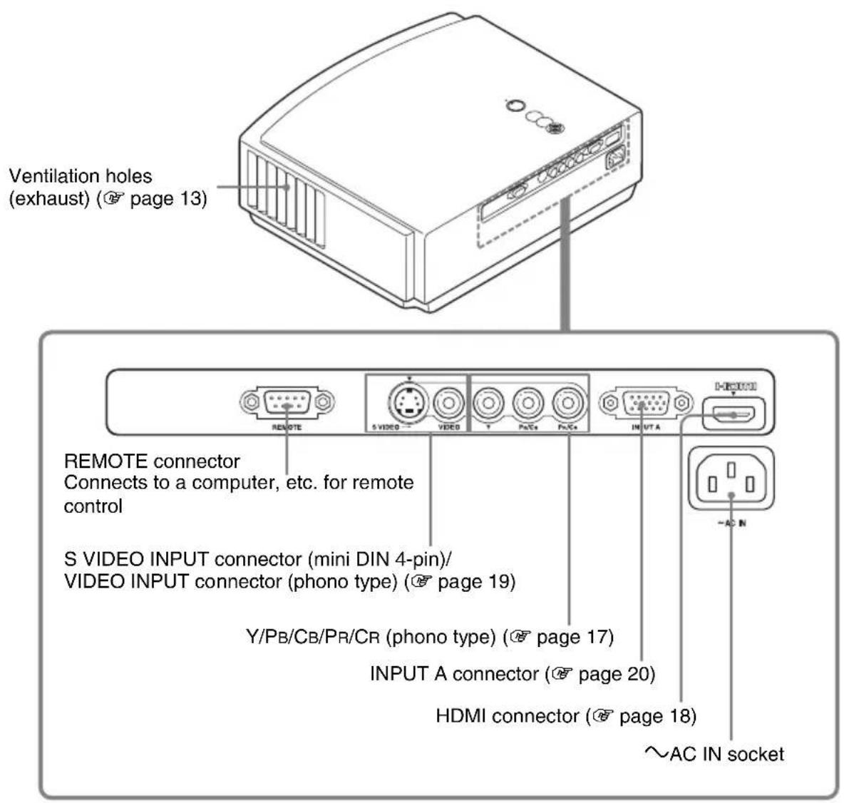
Rear/Bottom

Remote Control

Connections and Preparations
This section describes how to install the projector and screen, how to connect the equipment from which you want to project the picture, etc.
Unpacking
Check the carton to make sure it contains the following items:
- Remote control (1) and Size AA (R6) batteries (2)
- AC power cord (1) - Air filter (for replacement) (1)
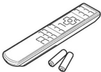
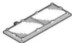
- Lens cap (1) When you have purchased the projector, the lens cap was fitted onto the lens. Remove this lens cap when you use the projector. - Operating Instructions (this manual)
Inserting the batteries into the remote control
Push and slide to open.
Insert the batteries ● side first as shown in the illustration. Inserting them forcibly or with the polarities reversed may cause a short circuit and may generate heat.

Caution about handling the remote control
- Handle the remote control with care. Do not drop or step on it, or spill liquid of any kind onto it.
- Do not place the remote in a location near a heat source, a place subject to direct sunlight, or a damp room.
Step 1: Installing the Projector
The projector displays pictures output from a VCR or other devices.
The projector can be used in various places and you can enjoy viewing beautiful pictures easily.
Before Setting Up the Projector
Unsuitable installation
Do not place the projector in the following situations, which may cause malfunction or damage to the projector.
Poorly ventilated location

Hot and humid

Locations subject to direct cool or warm air from an air-conditioner

Installing the projector in such a location may cause a malfunction of the unit due to moisture condensation or rise in temperature.
Near a heat or smoke sensor

Malfunction of the sensor may occur.
Very dusty and extremely smoky locations

Install in a location away from walls
To maintain the performance and reliability of the projector, allow at least 30 cm (11 7/8 inches) between the projector and walls.

Improper use
Do not do any of the following while using the projector.
Blocking the ventilation holes.
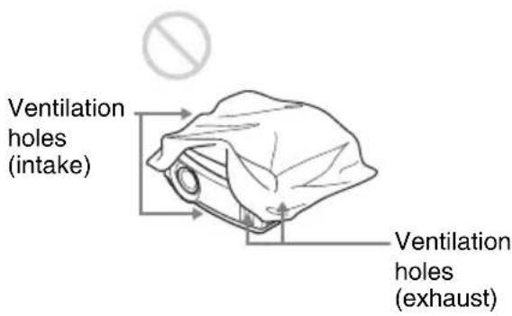
Tip
For details on the location of the ventilation holes (intake or exhaust), see “Location of Controls” on pages 8 to 9.
Tilting front/rear and left/right


Avoid using the projector tilted at an angle of more than 15 degrees.
Do not install the projector anywhere other than on a level surface or on the ceiling. Failing to set this mode when using the projector at high altitudes may result in uneven color uniformity and reducing the reliability of the effects of the lamp.
When installing the unit at altitudes
When using the projector at an altitude of 1,500 m or higher, set "Cooling Setting" in the Setup
menu to "High" ( page 46). Failing to set this mode when using the projector at high altitudes could have adverse effects, such as reducing the reliability of certain components.
Positioning the Projector and a screen
The installation distance between the projector and a screen varies depending on the size of the screen.
1 Determine the installation position of the projector and screen.
You can obtain a good quality picture if you position the projector with the center of the lens within the areas indicated in the gray areas in the illustration (VPL-AW15 only). Use the values a, b, c and d in the table on page 15 as a guide.

a: Minimum projection distance between the screen and the center of the projector's lens
b: Maximum projection distance between the screen and the center of the projector's lens
(VPL-AW15 only)
*c: Vertical distance between the center of the screen and the center of the projector's lens when using the maximum upper vertical lens shift feature
*d: Horizontal distance between the center of the screen and the center of the projector's lens when using the maximum horizontal lens shift feature
* The distances c and d indicated in the illustration show those in the lower or left direction. The same distances in the upper or right direction are appropriate for installation.
◆ For installation of the projector on a ceiling, see “Ceiling Installation.” ( page 66)
◆ For details on the lens shift feature, see “Step 3: Adjusting the Picture Position.” (page 21)
When using the 16:9 aspect ratio screen
Unit: mm (inches)
| Screen size (inches) | 40 60 70 | 80 100 12 | 0 140 160 | 180 200 | ||||||
| (mm) | 1016 1524 | 1778 203 | 2 2540 30 | 48 3556 4 | 064 4572 | 5080 | ||||
| a (minimum) | 1151(45 3 /8) | 1750(69) | 2049(80 11 /16) | 2348(92 1 /2) | 2946(116) | 3544(139 5 /8) | 4142(163 1 /8) | 4740(186 3 /4) | 5339(210 1 /4) | 5937(233 7 /8) |
| b (maximum) | 1885(74 1 /4) | 2849(112 1 /4) | 3332(131 1 /4) | 3814(150 1 /4) | 4779(188 1 /4) | 5744(226 1 /4) | 6709(264 1 /4) | 7673(302 1 /8) | 8638(340 1 /8) | 9603(378 1 /8) |
| *c | 324(12 3 /4) | 485(19 1 /8) | 566(22 3 /8) | 647(25 1 /2) | 809(31 7 /8) | 971(38 1 /4) | 1133(44 5 /8) | 1294(51) | 1456(57 3 /8) | 1618(63 3 /4) |
| *d | 221(8 3 /4) | 331(13 1 /8) | 387(15 1 /4) | 442(17 1 /2) | 552(21 3 /4) | 663(26 1 /8) | 773(30 1 /2) | 884(34 7 /8) | 994(39 1 /4) | 1105(43 1 /2) |
To calculate the installation measurements (SS: Screen Size)
a (minimum) = 29.909 (13 / 16) × SS - 44.886 (113 / 16)
b (maximum) = 48.239 (11 / 16) × SS - 44.869 (113 / 16)
c = 8.0899 ( 11 / 32 ) × SS
d = 5.5245(7 / 32) × SS
*VPL-AW15 only
When using the 4:3 aspect ratio screen (projecting a 4:3 picture)
Unit: mm (inches)
| Screen size (inches) | 40 60 70 | 80 100 12 | 0 140 160 | 180 200 | ||||||
| (mm) | 1016 1524 | 1778 203 | 2 2540 30 | 48 3556 4 | 064 4572 | 5080 | ||||
| a (minimum) | 1419 (56) | 2152 (84 3/4 ) | 2518 (99 1/4 ) | 2884 (113 5/8 ) | 3616 (142 1/2 ) | 4348 (171 1/4 ) | 5080 (200 1/8 ) | 5813 (228 7/8 ) | 6545 (257 3/4 ) | 7277 (286 5/8 ) |
| b (maximum) | 2317 (91 1/4 ) | 3498 (137 3/4 ) | 4088 (161) | 4679 (184 1/4 ) | 5860 (230 3/4 ) | 7041 (277 1/4 ) | 8221 (323 3/4 ) | 9402 (370 1/4 ) | 10583 (416 3/4 ) | 11764 (463 1/4 ) |
| *c | 396 (15 5/8 ) | 594 (23 1/2 ) | 693 (27 3/8 ) | 792 (31 1/4 ) | 990 (39) | 1188 (46 7/8 ) | 1386 (54 7/8 ) | 1584 (62 1/2 ) | 1782 (70 1/4 ) | 1980 (78) |
| *d | 270 (10 3/4 ) | 406 (16) | 473 (18 3/4 ) | 541 (21 3/8 ) | 676 (26 5/8 ) | 811 (32) | 947 (37 3/8 ) | 1082 (42 7/8 ) | 1217 (48) | 1352 (53 3/8 ) |
To calculate the installation measurements (SS: Screen Size)
a (minimum) = 36.609 (11/2) × SS - 44.886(113/16)
b (maximum) = 59.045 (2 3 / 8 ) × SS - 44.869 (1 13 / 16 )
c = 9.902 ( 13/32 ) × SS
d = 6.762(9 / 32) × SS
*VPL-AW15 only
2 Position the projector so that the lens is parallel to the screen.
Top view

3 Project an image on the screen and adjust the picture so that it fits the screen. ( page 21)
To project an image, connect video equipment to the projector. ( page 17)
Note
When using a screen with an uneven surface, stripes pattern may rarely appear on the screen depending on the distance between the screen and the projector or the zooming magnifications. This is not a malfunction of the projector.
Step 2: Connecting the Projector
When making connections, be sure to do the following:
- Turn off all equipments before making any connections.
- Use the proper cables for each connection.
- Insert the cable plugs properly; poor connection at the plugs may cause a malfunction or poor picture quality. When pulling out a cable, be sure to pull it out with holding the plug, not the cable itself.
- Refer to the operating instructions of the connected equipment.
Connecting to a VCR
To connect to a DVD player/recorder, Blu-ray Disc player or digital tuner equipped with component video connectors
![graph TD A["Rear of the projector"] --> B["Component video cable (not supplied)"] B --> C["AV amplifier"] C --> D["Speakers"] D --> E["DVD player/recorder, HDD recorder, Blu-ray Disc player, digital tuner, etc., with component video connectors"] style A fill:#f9f,stroke:#333 style B fill:#ccf,stroke…](/content/2026/08/1584768/images/584666035625a18d3cd4b0796a2a7f91089410d8c31d9ef1cba48ee2f13c82c2.jpg)
To connect to a DVD player/recorder and Blu-ray Disc player equipped with HDMI output
You can enjoy better picture quality by connecting a DVD player/recorder and Blu-ray Disc player equipped with HDMI output to the HDMI input of the projector.
![graph TD A["Rear of the projector"] --> B["Input A: HDMI"] B --> C["AV amplifier Speakers"] C --> D["To HDMI output"] D --> E["HDMI cable (not supplied)"] E --> F["Video signal flow"] style A fill:#f9f,stroke:#333 style C fill:#ccf,stroke:#333 style D fill:#cfc,stroke:#333 style E fill:#fcc,stroke:#…](/content/2026/08/1584768/images/1b5a6ca84294872baa7d1d4a22a7f312d625151c33a3377671ec74fda05e05e1.jpg)
Notes
- When connecting equipment to the HDMI input of the projector, be sure to use equipment that have acquired the HDMI logo.
- When connecting an HDMI cable to the projector, make sure the ▼ mark on the upper part of the HDMI input of the projector and the ▼ mark on the connector of the cable is set at the same position.
- If the picture from equipment connected to the projector with an HDMI cable is not clear, check the settings of the connected equipment.
To connect to a VCR equipped with the S video connector or video connector
You can connect a DVD player/recorder, hard disk video recorder, VCR or laser disk player, which is not equipped with component video connectors. See also the instruction manual of each equipment.
![graph TD A["Rear of the projector"] --> B["S VIDEO"] B --> C["Video equipment"] C --> D["AV amplifier"] D --> E["S video or video cable (not supplied)"] E --> F["Video signal flow"] style A fill:#f9f,stroke:#333 style B fill:#ccf,stroke:#333 style C fill:#cfc,stroke:#333 style D fill:#fcc,stroke:#33…](/content/2026/08/1584768/images/8259ff726347ab2250606350a7ff7e50d46750eb0a632f9dd38f9d3005dea8a1.jpg)
Tip
In order to enjoy better video performance, use S Video connector. If the equipment to be connected has no S video connector, connect the cable to the video output.
Connecting to a Computer
![graph TD A["Rear of the projector"] --> B["HD-Sub15 pin cable (optional) or HDMI cable (optional)"] B --> C["Computer"] D["Video signal flow"] --> B E["When using an optional HDMI cable, be sure to use a cable that has acquired an HDMI logo."] --> B F["AND Gate"] --> B G["Input A"] --> B H["Input B"…](/content/2026/08/1584768/images/28eb8a01cc9b8f2e2076ce280cdb4a725aa529d984feaeb699b0314cbf42575c.jpg)
Tip
Set "Input-A Signal Sel." in the Setup ☐ menu to "Auto" or "Computer." If the input signal does not appear properly, set it to "Computer." ( page 47, 54)
Notes
- When connecting an HDMI cable, make sure the ▼ mark on the upper part of the HDMI input of the projector and the ▼ mark on the connector of the cable is set at the same position.
- If you set your computer, such as a notebook type, to output the signal to both computer's display and this equipment, the picture of the equipment may not appear properly. Set your computer to output the signal to only the external monitor. For details, refer to the computer's operating instructions supplied with your computer. For settings of the computer, consult with the manufacturer of the computer.
- If the picture from equipment connected to the projector with an HDMI cable is not clear, check the settings of the connected equipment.
Step 3: Adjusting the Picture Position
Project an image on the screen and then adjust the picture position.


Tip
The I/ ① (On/standby), INPUT, MENU, and ▲/▼/◀/▶/◎ (joystick) buttons on the top panel of the projector function the same as those on the remote control.
Note
Depending on the installation location of the projector, you may not control it with the remote control. In this case, point the remote control to the screen instead of the projector.

Lights in red.

1 After connecting the AC cord to the equipment, plug the AC cord into a wall outlet.
The I/ ① (On/standby) indicator lights in red and the projector goes into standby mode.


Flashes in green for a few seconds, and then lights in green.


2 Press the I/⏻ (On/standby) switch to turn on the projector.
The I/ ① (On/standby) indicator flashes in green, and then lights in green.
3 Turn on the equipment connected to the projector.
Refer to the operating instructions of the connected equipment.
4 Press INPUT to project the picture on the screen.
Each time you press the button, the input indication and equipment to be projected change. ( page 27)
Tips
- You can select the desired language for the menu screen. For details, refer to "Step 4: Selecting the Menu Language". ( page 25)
- When "Auto Input Search" is set to "On" in the Function menu, the input terminal with effective signals is automatically displayed by pressing INPUT. ( page 48)
5 Move both LENS SHIFT dials (VPL-AW15 only) to adjust the picture position.

To adjust the horizontal position
Turn the LENS SHIFT dial right or left.
The picture projected on the screen moves right or left by a maximum of 25% of the screen size from the center of the lens.
25% 1 screen width 25%

Top view
☐: Picture position when moving the picture to the left at maximum
☐: Picture position when moving the picture to the right at maximum
To adjust the vertical position
Turn the LENS SHIFT dial up or down.
The picture projected on the screen moves up or down by a maximum of 65% of the screen size from the center of the lens.

Note
When you use both the horizontal and vertical lens shift features at the same time, you can move the picture vertically by a maximum of 25% of the screen size.

6 Adjust the picture size using the zoom lever.

7 Adjust the focus using the focus ring.
To adjust the tilt of the installation surface
If the projector is installed on an uneven surface, use the adjusters to keep the projector level.

Note
Be careful not to catch your finger when turning the adjusters.
Step 4: Selecting the Menu Language
You can select one of 16 languages for displaying the menu and other on-screen displays. The factory default setting is English. To change the current menu language, set the desired language with the menu screen.


![Picture Picture Mode Standard Reset Cinema Black Pro Contrast 80 —— Brightness 50 —— Color 50 —— Hue 50 —— Color Temp. Middle Sharpness 50 —— NR Off DDE Off Black Level Adj. Off Gamma Correction Gamma2 Set: Set: Exit: [OK]](/content/2026/08/1584768/images/2749fe7778a144b578e4a9e9c6df5946a2bab09013865cc9ee43e9bce622108b.jpg)
1 Press MENU.
The menu appears.




2 Press ↑/↓ to select the Setup menu, and press → or
The setting items of the selected menu appears.
3 Press ↑/↓ to select "Language," and press → or
4 Press ↑/↓/←/→ to select a language, and press ⊕
The menu changes to the selected language.
To clear the menu
Press MENU.
Projecting
This section describes how to operate the projector to view the picture from the equipment connected to the projector. It also describes how to adjust the quality of the picture to suit your taste.
Projecting the Picture on the Screen


Example: To view the picture from the video equipment connected to the VIDEO INPUT connector.
1 Power on both the equipment and the device connected to the equipment.
2 Press INPUT repeatedly to select the input you want to project on the screen.
Display the indication of the input you want.
| To view the picture from Press INPUT to display | |
| Video equipment connected to the VIDEO INPUT connector Video | |
| Video equipment connected to S VIDEO INPUT connector S-Video | |
| RGB/component equipment connected to the INPUT A connector Input-A* | |
| Component equipment connected to Y/PB/CB/PR/CR connectors | Component |
| Equipment connected to the HDMI connector | HDMI** |
* Set the “Input-A Signal Sel.” setting in the Setup ☐ menu according to the signal input. When you set it to “Auto,” and cannot display the picture properly, select an appropriate signal according to the input signal. ( page 47, 50, 61)
**The color gradation of the dark area or the bright area may become unclear when a signal other than those from HDMI standard cable is input. Adjust the Brightness and the Contrast in the Picture menu. ( page 41)
Tip
When “Auto Input Search” is set to “On” in the Function ☐ menu, the input terminal with effective signals is automatically displayed by pressing INPUT.
Turning Off the Power
1 Press the I/⏻ (On/standby) switch.
A message “POWER OFF?” appears on the screen.
2 Press the I/⏻ (On/standby) switch again before the message disappears.
The I/ ① (On/standby) indicator flashes in green and the fan continues to run to reduce the internal heat. First, the I/ ② (On/standby) indicator flashes quickly, during which you will not be able to light up the I/ ③ (On/standby) indicator with the I/ ④ (On/standby) switch.
3 Confirm that the fan stops running and the I/⏻ (On/standby) indicator lights in red.
You can turn off the projector by holding the I/⏻ (On/standby) switch for about 1 second, instead of performing the above steps.
Selecting the Wide Screen Mode
You can enjoy various wide screen modes according to the video signal received.

* RCP button: VPL-AW15 only
Press WIDE MODE.
Each time you press the button, you can change the “Wide Mode” setting in turn.
You can also select it using the menu. ( page 44)
![graph TD A["Original image When the Wide Mode is operated"] --> B["Large circular shapes inside a grid"] B --> C["Squeezed: Large circles inside a grid"] C --> D["Large circles inside a grid"] D --> E["Squeezed: Large circles inside a grid"]](/content/2026/08/1584768/images/d495ad19cb7111d315dad5f76a748ed3564e93c78e2d2dc0e02ec28ee2564291.jpg)
Letterbox picture with side panels
![graph TD A["Letterbox picture"] --> B["Rectangle with circles"] C["Rectangle with circles"] --> D["Rectangle with circles"]](/content/2026/08/1584768/images/9617b95448168f7edd78a17c488d9dded15b182d9adcf3954687c838a8d08b68.jpg)
Wide Zoom
A 4:3 aspect ratio picture is enlarged over the entire screen properly. The upper and lower portions of the screen are slightly cut off.
Normal
A picture with normal 4:3 aspect ratio is displayed in the center of the screen to fill the vertical screen size.
Full
A picture squeezed to 4:3 is displayed with the correct aspect ratio. A 4:3 picture is enlarged horizontally to fit the 16:9 screen.
Tip
Squeezed: An original 16:9 aspect ratio picture is recorded horizontally compressed to a 4:3 picture.
Zoom
A normal 16:9 aspect ratio picture is enlarged vertically and horizontally in the same ratio to fill the screen. Use this mode to view a letterbox picture or a letterbox picture with side panels.
If the subtitle of a movie, etc. is hidden and cannot be seen, adjust the screen with "Vertical Size" and "V Center" to display the subtitle. ( page 45)
Full 1 (When the PC signal is input)
Displays a picture on the whole of the screen without changing the aspect ratio of the original picture.

Full 2 (When the PC signal is input)
Displays a picture on the whole of the screen.
Note
You can adjust the vertical position of the picture with "V Center" and "Vertical Size" in the Screen

menu only when "Zoom" is selected. ( page 45)
Notes on selecting the wide screen mode
The projector is featured with the WIDE MODE. When changing the settings of WIDE MODE, it must be noted as below.
- Changing the aspect ratio of the original picture will provide a different look from that of the original image.
- Note that if the projector is used for profit or for public viewing, modifying the original picture by switching to the wide mode may constitute an infringement of the rights of authors or producers, which are legally protected.
Selecting the Picture Viewing Mode
You can select the picture viewing mode that best suits the type of program or room conditions.

* RCP button:
VPL-AW15 only
Press one of the PICTURE MODE buttons (DYNAMIC, STANDARD, CINEMA and USER 1, USER 2 and USER 3).
DYNAMIC
Enhances picture contrast and sharpness.
STANDARD
The quality of the picture becomes less rough than the one selected by "DYNAMIC".
CINEMA
Recommended when viewing a movie in the dark place.
USER 1, USER 2 and USER 3
You can adjust the quality of the picture to suit your taste and store the settings into the selected memory of the projector. Press one of the USER 1, USER 2 and USER 3 buttons, then adjust the picture by using the buttons on the remote control or the menus (pages 32 and 40). The settings are stored, and you can view the picture with the adjusted picture quality by pressing the button.
Adjusting the Picture Quality
You can adjust the picture quality that suits your taste by selecting the adjustment items with the remote control. The adjusted data can be stored in each picture mode.

* RCP button: VPL-AW15 only
1 Press ADJ PIC.
Each time you press the button, the following adjustment windows* are displayed in sequence.
* Some of the above adjustment windows will not be displayed depending on the input signal. For details, see "Input Signals and Adjustable/Setting Items."
(page 64)
![graph TD A["Advanced Iris"] --> B["Lamp Control"] B --> C["Contrast"] C --> D["Brightness"] D --> E["Color"] E --> F["Hue"] F --> G["Color Temp."] G --> H["Sharpness"] H --> I["NR"] I --> J["DDE"] J --> K["Black Level Adj."] K --> L["Gamma Correction"]](/content/2026/08/1584768/images/7b7c6f6faa35ae6c27628bddb892b70c28d2b928c232a47f2353108c86730496.jpg)

Example: To adjust the contrast
For details on each adjustment, see the Picture 📄 menu. ( page 40)
2 Make the setting or adjustment on an item.
When changing the adjustment level
To increase the value, press → .
To decrease the value, press ←.
When changing the setting
Press ↑/↓ to change the setting.
Adjusting the Picture Using Real Color Processing (VPL-AW15 only)
The Real Color Processing (RCP) feature allows you to adjust the color and hue of each target of the projected picture you specify independently. You can thus obtain a picture more suitable to your taste.
Tip
Freeze the scene of the video source when you are adjusting the picture using Real Color Processing.


1 Press RCP on the remote control.
2 Press ↑/↓ to select "User 1," "User 2" or "User 3," then press →.
The RCP (Real Color Processing) window appears.
3 Select the target color you want to adjust.
Repeat steps ① and ② described below to specify the target color.
①Press ↑/↓ to select "Color Select," then press ←/→ to select the color you want to adjust among "Red," "Yellow," "Green," "Cyan," "Blue" and "Magenta."
Only the portions that correspond to the specified color will be colored and the other portions will be displayed in black and white. The reference palette in the RCP window also shows the adjustable colors. Select the desired setting to adjust the color on the projected image using the reference palette as a guide.
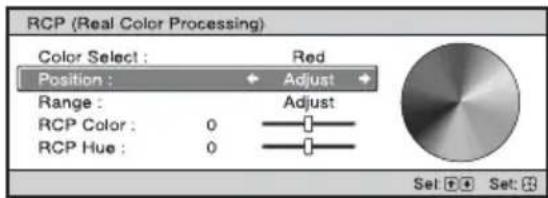
② Press ↑/↓ to select “Position” or “Range,” and specify it more delicate color position and color range you want to adjust using ←/→.
4 Adjust the color of the specified portions.
Press ↑/↓ to select “RCP Color” or “RCP Hue,” then adjust the color or hue of the portions selected in step 3 to suit your taste using ←/→ while watching the projected picture. The picture is returned to normal color during adjustment.
5 After the adjustment is complete, press
The RCP window disappears and the picture of step 2 is appeared. Then after a few seconds, normal picture is restored. The adjustments you have made will be reflected on the picture projected on the screen.
Tip
There are some limitations on selection of position and range.
Using Other Functions
You can temporarily turn off or pause a projected picture.

Press PIC MUTING.
Press to temporarily turn off a projected picture. To return to the previous screen, press PIC MUTING again.
Press FREEZE.
A projected picture can be paused to be displayed. "FREEZE" is shown on the screen when a button is pressed. To return to the previous screen, press FREEZE again.
Note
Available for only computer signal.
Using the Menus
This section describes how to make various adjustments and settings using the menus.
Operation through the Menus
The projector is equipped with an on-screen menu for making various adjustments and settings. Some of the adjustable/setting items are displayed in a pop-up menu, in a setting menu or adjustment menu with no main menu, or in the next menu window. If you select an item name followed by an arrow (▶), the next menu window with setting items appears. To change the on-screen menu language, see “Step 4: Selecting the Menu Language.” ( page 25)


1 Press MENU.
The menu window appears.
2 Press ↑/↓ to select a menu item, and press → or ⊕
The items that can be set or adjusted with the selected menu appear. The item presently selected is shown in yellow.

Pop-up menu
Setting items

Setting menu

Adjustment menu

Next menu window
Setting items
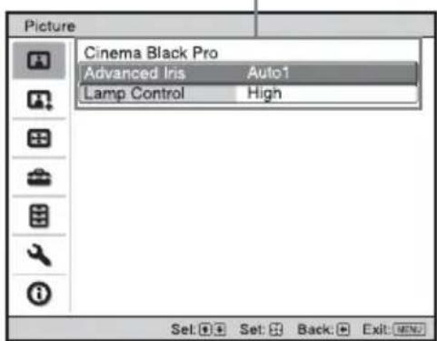
(Menu window of VPL-AW15)
3 Press ↑/↓ to select an item you want to set or adjust and press

The items that can be set appear in the pop-up menu, setting menu, adjustment menu, or in the next menu window.
4 Make the setting or adjustment of an item.
When changing the adjustment level
To increase the value, press /→ . To decrease the value, press /← . Press restore the previous screen.
When changing the setting
Press ↑/↓ to change the setting.
Press -to restore the previous screen.
You can restore the previous screen using ← depending on the selected item.
Items that cannot be adjusted
Adjustable items differ depending on the input signal. The items that cannot be adjusted or set do not appear in the menu.
(page 64)
To clear the menu
Press MENU.
To reset the picture that has been adjusted
Select "Reset" from Picture menu.

When the screen display appears, select "Yes" using ← and press ⚠️ All of the following settings are reset to its factory preset value.
“Advanced Iris”, “Lamp Control”, “Contrast”, “Brightness”, “Color”, “Hue”, “Color Temp”, “Sharpness”, “NR”, “DDE”, “Black Level Adj.” and “Gamma Correction” on the Picture menu
To reset the items that have been adjusted
Select an item in the Menu screen, and display the pop-up menu, the setting menu, and the adjustment menu. Press the RESET on the remote control to reset only the selected settings to its factory preset value.
Note
RESET on the remote control is available only when the adjustment menu or the setting menu is selected.
Picture Menu
The Picture menu is used for adjusting the picture.

Adjust Picture menu
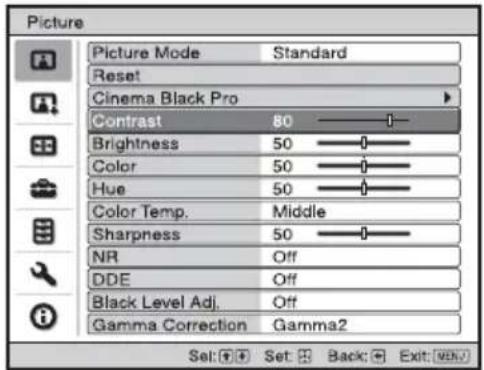
| Picture Mode | You can select the picture viewing mode that best suits the type of picture or the environment.Dynamic: Select this for enhanced picture contrast and sharpness to reproduce color tones.Standard: Select this to reduce roughness compared to viewing the picture with Dynamic.Cinema: Select this for watching movies, etc. in a dark environment.User 1, User 2, User 3: You can adjust the quality of the picture to suit your taste and then store the settings. Once the settings are stored, you can view the picture with the adjusted picture quality by pressing the PICTURE MODE on the remote control.To store the settings1 Select User 1, User 2, or User 3.2 Adjust the items you want in the menus.TipsYou can also adjust the picture quality in “Dynamic”, “Standard” or “Cinema”, and store the settings. To reset everything to the factory settings, select “Reset” in the menu.Some items may not be displayed on the Picture menu, depending on the type of input signal. For details, see “Input Signals and Adjustable/Setting Items” ( page 64). |
Cinema Black Pro Advanced IrisSwitches the iris function during projection.VPL-AW15Auto 1: Automatically switches to an optimum iris according to a projected scene. The contrast of the scene is emphasized most.Auto 2: An optimum iris becomes smaller than when set to “Auto 1”. The contrast of the scene becomes reduced.Sensitivity: If “Auto1” or “Auto2” is selected, either “Recommend”, “Fast”, or “Slow” can be selected according to the desired response speed with Sensitivity Mode.Manual: Manually adjusts the Iris. Off: Normal contrast.VPL-AW10Auto: Automatically switches to an optimum iris according to a projected scene. The contrast of the scene is emphasized most.On: Emphasizes the contrast and enhances the black.Off: Normal contrast. Off: Normal contrast.VPL-AW10Auto: Automatically switches to an optimum iris according to a projected scene. The contrast of the scene is emphasized most.On: Emphasizes the contrast and enhances the black.Off: Normal contrast. | |
| Lamp ControlSwitches the lamp wattage during projection.High: Normal wattage.Low: Enhances the black by reducing the lamp wattage.TipWhen you switch from “Low” to “High”, the number of turns of the fan increases, and the fan noise becomes slightly louder. | |
| Contrast Adjusts the white area of pictures (white level).The higher the setting, the greater the contrast. The lower the setting, the lower the contrast.You can make adjustments by pressing the CONTRAST+/- on the remote control. | |
| Brightness Adjusts the brightness of the picture.The higher the setting, the brighter the picture. The lower the setting, the darker the picture.You can make adjustments by pressing the BRIGHT+/- on the remote control. | |
| Color Adjusts the intensity of the color density.The higher the setting, the greater the intensity. The lower the setting, the lower the intensity. | |
| Hue Adjusts the color tone.The higher the setting, the more greenish the picture becomes. The lower the setting, the more reddish the picture becomes. | |
| Color Temp. Adjusts the color temperature.High: Gives white colors a blue tint.Middle: Gives a neutral tint between “High” and “Low”.Low: Gives white colors a red tint.Custom1, Custom2, Custom3: Enables you to adjust, set, and store your favorite color temperature. | |
| Sharpness Sharpens the outline of the picture, or reduces the noise.The higher the setting, the sharper the picture. The lower the setting, the softer the picture, thus reducing the noise. | |
| NR (Noise Reduction) R | Reduces the roughness or noise of the picture.Usually, select “Off”.If the picture is rough or noisy, select a setting from among “Low”, “Middle” or “High” according to the input signal source. |
| DDE (Dynamic Detail Enhancer) | According to the film source you have selected, make a setting for playback.Film: Normally, select this option. Reproduces the 2-3 Pull-Down film sources with smooth picture movement. When the video signal with a format other than the 2-3 Pull-Down is input, “Progressive” is automatically selected.Progressive: Converts an interlace format video signal to a progressive format.Off: Plays a video signal in an interlace format without converting. |
| Black Level Adj.(Adjust) | Produces a bolder, dynamic picture.Set according to the input signal source.High: Gives higher emphasis to the black color.Low: Gives lower emphasis to the black color.Off: Cancels this feature. |
| Gamma Correction | Adjusts the response characteristics of the tone of the picture.Select a favorite tone from three options.Gamma1: Makes a scene a little brighter.Gamma2: Makes a scene brighter.Gamma3: Makes a scene darker.Off: Gamma Correction is “Off”. |
Advanced Picture Menu (VPL-AW15 only)
The Advanced Picture is used for adjusting the picture more.
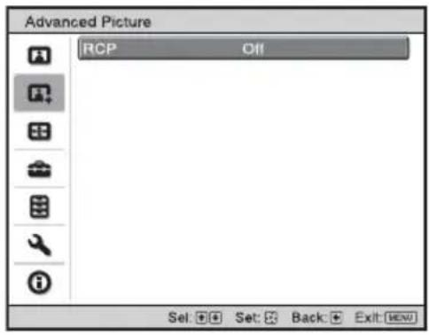
| RCP (Real Color Processing)(VPL-AW15 only) | You can adjust the color and hue of each selected portion of the picture independently.User 1, User 2, User 3: You can adjust the picture using Real Color Processing and store the settings. Once the settings are stored, you can view the picture with the adjusted picture quality.Off: Cancels this feature.For details, see “Adjusting the Picture Using Real Color Processing”.( page 33) |
Screen Menu
The Screen menu is used to adjust the input signal. You can adjust the size of the picture, and select wide screen mode, etc.
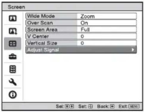
Adjust Screen menu

| Wide Mode (When the input signal is moving picture) | You can set the aspect ratio of the picture to be displayed for the current input signal. This item is enabled only when a moving picture (preset memory numbers 1 to 14) ( page 61) is provided.Wide Zoom: A 4:3 aspect ratio picture is enlarged over the entire screen properly. The upper and lower portions of the screen are slightly cut off.Normal: A picture with normal 4:3 aspect ratio is displayed in the center of the screen to fill the vertical screen size.Full: A picture squeezed to 4:3 is displayed with the correct aspect ratio.A 4:3 picture is enlarged horizontally to fit the 16:9 screen.Zoom: A normal 16:9 aspect ratio picture is enlarged vertically and horizontally in the same ratio to fill the screen. |
| Wide Mode (When the PC signal is input) | You can set the aspect ratio of the picture to be displayed for the current input signal. This item is enabled only when an PC signal is input.Full 1: Displays a picture on the whole of the screen without changing the aspect ratio of the original picture.Full 2: Displays a picture on the whole of the screen.Zoom: A normal 16:9 aspect ratio picture is enlarged vertically and horizontally in the same ratio to fill the screen. |
| Over Scan Hides the outline of the picture.On: Hides the outline of the input picture. Select this setting when noise appears along the edge of the picture.Off: Projects the whole of the input picture.TipTo adjust the display area, refer to “Blanking” on the installation menu ( page 49). (VPL-AW15 only) | |
| Screen Area | Selects the size of the picture when a Hi-Vision picture is overscanned.Full: Expands the picture on the whole of the screen.Through: Does not expand the picture on the whole of the screen.NoteThis item is effective only when a Hi-Vision signal (preset memory No. 10 and 11) is input and “On” is selected in “Over Scan”. |
| V Center Adjust the whole picture by moving up and down on the screen.The entire screen moves up as the selected number increases and moves down as the selected number decreases.NoteThis item is adjustable only when “Zoom” is selected. | |
| Vertical Size Reduces or enlarges the picture vertically.The screen is enlarged as the setting increases and reduced as the setting decreases. If the subtitle of a movie, etc. cannot be seen, use this together with “V Center”.NoteThis item is adjustable only when “Zoom” is selected. | |
| Adjust Signal You can adjust the input signal.APA: Adjusts the position of the image signal automatically for “Phase”, “Pitch”, and “Shift”.Phase: Adjusts the dot phase of the panel and the computer signal.Adjust the picture to the point where it looks clearest.Pitch: Adjusts the horizontal size of the picture from a computer.The higher the setting, the wider the picture. The lower the setting, the narrower the picture. Adjust the setting to match the number of dots of the input signal.Shift: Adjusts the position of the picture.H: As the setting for H (horizontal) increases, the picture moves to the right, and as the setting decreases, the picture moves to the left. Use ← / → to adjust the horizontal position.V: As the setting for V (vertical) increases, the picture moves up, and as the setting decreases, the picture moves down. Use ↑ / ↓ to adjust the vertical position. | |
Setup Menu
The Setup menu is used to change the factory preset settings, etc.

| Status Sets whether or not | the on-screen display is displayed.Set to “Off” to turn off the on-screen displays except for the menus, message when turning off the power, and warning messages. |
| Language | Selects the language used in the menu and on-screen displays.Available languages are: English, Dutch, French, Italian, German, Spanish, Portuguese, Russian, Swedish, Norwegian, Japanese, Chinese (Simplified Chinese), Chinese (Traditional Chinese), Korean, Thai and Arabic. |
| Cooling Setting Use this item | when using the projector at high altitudes.High:Use this setting when using the projector at an altitude of 1,500 m or higher.Standard:Use this setting when using the projector at normal altitudes.NoteWhen this item is set to “High”, the fan noise becomes slightly louder since the number of fan rotation increases. |
| Standby Mode Lowers the power consumption in standby.When set to “Standard” the power consumption in standby becomes normal.When set to “Low”, the power consumption in standby mode is lowered. | |
| Power Saving Sets the power saving mode.When set to “On”, the projector goes into power saving mode if no signal is input for 10 minutes. At that time, after the I/⏻ (On/ standby) indicator flashes, it will light in orange and the screen becomes dark. In power saving mode, the power saving mode is cancelled if a signal is input or any button is pressed. If you do not want to set the projector to power saving mode, select “Off”. | |
| Input-A Signal Sel. Selects | the type of signal input from the equipment connected to the INPUT A connector.Selects the type of signal input from the equipment by selecting “Input-A” with the INPUT.Auto: Selects the input signal type automatically.Computer: Inputs the signal from a computer.Video GBR: Inputs the signal from a TV game or HDTV broadcast.Component: Inputs the component signal from a DVD player/ recorder, Blu-ray Disc player, digital tuner, etc.NoteWhen the input signal is not displayed correctly with this item set to “Auto,” select the item according to the input signal. |
| Color System Selects the color system of the input signal.Auto: Selects the color system of the input signal automatically from among NTSC3.58, PAL, SECAM, NTSC4.43, PAL-M, PAL-N, or PAL60.“NTSC3.58”-“PAL-N”: Allows you to set the color system to the selected system manually.NoteNormally, set this to “Auto.” If the picture is distorted or colorless, select the appropriate color system for the input signal. | |
| Lamp Setting | When replacing the lamps, set the desired lamp setting.( page 57) |
Function Menu
The Function menu is used for changing the settings of the various functions of the projector.
![Function Smart APA On Auto Input Search Off Background Blue Set: Set: Back: Exit: [OK]](/content/2026/08/1584768/images/4adbc1c639833413aba0a787c91417a297bf2d29ffa6f5343eccafc2ade39df6.jpg)
| Smart APA | With this item set to On, the APA function works automatically for a signal input from a computer so that the picture can be seen clearly. You can also activate the APA function by pressing the APA on the remote control.TipThe APA (Auto Pixel Alignment) automatically adjusts the input signal from a computer so that the picture can be seen clearly. |
| Auto Input Search Detects the input signal and displays the detected input signal automatically when the INPUT is pressed.When set to “On”, by pressing the INPUT, the projector detects the presence of an input signal in the order of Component, HDMI, Video, S-video, or Input-A signal and displays the input connector of the present input signal.Set this to “Off” when selecting an input connector without an input signal or when selecting the input connector manually. | |
| Background Selects the background color of the screen when no signal is input.You can select “Black” or “Blue”. | |
Installation Menu
The Installation menu is used for changing the installation settings.

| V Keystone | Corrects the vertical trapezoidal distortion of the picture.When the bottom of the trapezoid is longer than the top ( ):Sets a lower value (- direction)When the top of the trapezoid is longer than the bottom ( ):Sets a higher value (+ direction).NoteDepending on the picture position adjusted with the lens shift feature, the aspect ratio of the picture may change from the original or picture distortion may occur with V Keystone adjustment. |
| Image Flip | Flips the picture on the screen horizontally and/or vertically.Off: The picture does not flip.HV: Flips the picture horizontally and vertically.H: Flips the picture horizontally.V: Flips the picture vertically.Use this item for installation for the backside projection or ceiling installation. |
| Blanking (VPL-AW15 only) | This feature allows you to adjust the display area.Select each screen edge “left / right / up / bottom” on the Blanking adjustment screen with ↑/ ↓. Adjust the desired Blanking value with ←/ →.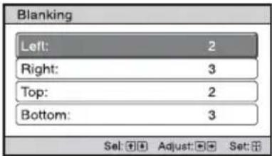 NoteWhen both the “Blanking” and the “V Keystone” are adjusted at the same time, the “Blanking” cannot be adjusted correctly. When using the “Blanking”, make sure that you set the “V Keystone” to “0”. NoteWhen both the “Blanking” and the “V Keystone” are adjusted at the same time, the “Blanking” cannot be adjusted correctly. When using the “Blanking”, make sure that you set the “V Keystone” to “0”. |
Information Menu
The Information menu displays the model name, serial number, the horizontal and vertical frequencies of the input signal and the cumulated hours of usage of the lamp.

| Model Name Displays the model name (VPL-AW15 or VPL-AW10) and the serial number. |
| Serial No. Displays the serial number. |
| fH (horizontal frequency) Displays the horizontal frequency of the input signal. |
| fV (vertical frequency) Displays the vertical frequency of the input signal. |
| Memory No. Displays the preset memory number of the input signal. |
| Signal type Displays the type of the input signal. |
| Lamp Timer Indicates how long the lamp has been turned on (total usage). |
Notes
- fH (horizontal frequency) and fV(vertical frequency) may not be displayed depending on the input signal used on the projector.
- You cannot change any items listed above.
About the Preset Memory No.
This projector has 39 types of preset data for input signals (the preset memory). When the preset signal is input, the projector automatically detects the signal type and recalls the data for the signal from the preset memory to adjust it to an optimum picture. The memory number and signal type of that signal are displayed in the Information menu.
You can also adjust the preset data through the Screen menu.
This projector also contains 20 different user memories beside the preset memories used for inputting computer signals. You can save input signals that have not been preset on these user memories.
When an unpreset signal is input for the first time, a memory number is displayed as 0. When you adjust the data of the signal in the Screen menu, it will be registered to the projector. If more than 20 user memories are registered, the oldest memory is always overwritten.
See the chart on page 61 to find if the signal is registered to the preset memory.
Note
When the aspect ratio of input signal does not match the screen size, a part of the screen is displayed in black.
Others
This section describes how to solve the problems, how to replace the lamp and air filter, etc.
Troubleshooting
If the projector appears to be operating erratically, try to diagnose and correct the problem using the following instructions. If the problem persists, consult with qualified Sony personnel.
Power
| Symptom Cause and Remedy | |
| The power is not turned on. | → After about 1 minute, turn the power on.→ Close the lamp cover securely, then tighten the screws securely.( page 56)→ Close the air filter cover securely. ( page 57)→ Check warning indicators. ( page 53) |
Picture
| Symptom Cause and Remedy | |
| No picture. | → Check that the proper connections have been made.( page 17)→ Select the input source correctly using the INPUT.( page 27)→ Set the computer signal to output from an external monitor.→ Set the computer signal to output only to an external monitor.→ Select “Computer,” “Component” or “Video GBR” for “Input-A Signal Sel.” on the Setup menu according to the input signal. ( page 47) |
| The picture from the INPUT A connector is colored strange. | → Select “Computer,” “Component” or “Video GBR” for “Input-A Signal Sel.” on the Setup menu according to the input signal. ( page 47) |
| The picture from the VIDEO INPUT or S VIDEO INPUT connector is colored strange. | → Adjust the picture of the Picture menu. ( page 40)→ Set “Color System” in the Setup menu to match the color system being input. ( page 47) |
| The color gradation of the dark area or the bright area becomes unclear when an HDMI signal is input. | → The color gradation of the dark area or the bright area may become unclear when a signal other than those from HDMI standard cable is input. Adjust the “Brightness” and the “Contrast” in the Picture menu. ( page 41) |
| The picture is too dark. | → Adjust the “Contrast” or “Brightness” of the Picture menu properly. ( page 41) |
| The picture is not clear. | → Adjust the focus using the focus ring. ( page 24)→ Condensation has accumulated on the lens. Leave the projector for about 2 hours with the power on. |
| The picture flickers. | → Activate “APA”, then adjust the current input signal.→ Adjust “Phase” for “Adjust Signal” in the Screen menu properly. ( page 45) |
On-screen display
| Symptom Cause and Remedy | |
| On-screen display does not appear. | → Set “Status” in the Setup [icon] menu to “On.” (page 46)→ Check if the I/↓ (On/standby) indicator should light in green. |
| The model name does not disappear from the screen. | → The display mode of the projector may be set at the time of purchase. Consult with your local dealer or qualified Sony personnel. |
Remote control
| Symptom Cause and Remedy | |
| The remote control does not work. | → Batteries could be weak. Replace them with new batteries.( page 11)→ Insert the batteries with the correct polarities. ( page 11)→ If there is a fluorescent lamp near the remote control detector, the projector may work improperly or inadvertently. |
Others
| Symptom Cause and Remedy | |
| The fan is noisy. | → Check the setting of “Cooling Setting” in the Setup [icon] menu. (page 46)→ Make sure that the room temperature is not too high.→ Check the installation conditions. (page 12)The number of fan rotation increases to maintain the product reliability of the projector’s components in a room, where the temperature is higher than normal. The fan noise becomes slightly louder. The approximate normal temperature is 25°C. |
| Image is left on the screen.(image retention) | → When High contrast non-moving images are displayed for a long period of time, there may be some image retention on the screen. This is only a temporary condition. Turning off the power for a while will eliminate the retained image. |
Warning Indicators
The I/⏻ (On/standby) or LAMP/COVER indicator lights up or flashes if there is any trouble with your projector.

| Symptom Cause and Remedy | |
| LAMP/COVER flashes in red. (A repetition rate of 2 flashes) | → Close the lamp cover securely, then tighten the screws securely. ( page 56)→ Close the air filter cover securely. ( page 57) |
| LAMP/COVER flashes in red. (A repetition rate of 3 flashes) | → The lamp has reached the end of its useful lifespan. Replace the lamp. ( page 55)→ The lamp has reached a high temperature. Wait until the lamp cools, and then turn on the power again. |
| I/⏻ (On/standby) flashes in red. (A repetition rate of 4 flashes) | → The fan is broken. Consult with qualified Sony personnel. |
| I/⏻ (On/standby) flashes in red. (A repetition rate of 2 flashes) | → The internal temperature is unusually high. Check to ensure that if nothing is blocking the ventilation holes or whether or not the projector is being used at high altitudes. |
| I/⏻ (On/standby) flashes in red. (A repetition rate of 6 flashes) | → Press the I/⏻ (ON/STANDBY) switch to turn on the projector. If the power is not turned on, disconnect the AC power cord, then confirm the ON/STANDBY lamp is turned off. After about 10 seconds, reconnect the AC power cord and turn on the power again. If the indicators still light up, the electrical system has a problem. Consult with qualified Sony personnel. |
Note
When a warning indicator other than the above starts flashing, and the symptom persists even after carrying out the above methods, consult with qualified Sony personnel.
Warning messages
| Message Cause and Remedy | |
| High temp.! Lamp off in 1 min. | →Turn off the power.→Check to ensure that nothing is blocking the ventilation holes.( page 13) |
| Frequency is out of range! | →Frequency is out of range. Input a signal that is within the acceptable frequency range of the projector. |
| Please check Input-A Signal Sel. | →Set “Input-A Signal Sel.” in the Setup menu to “Computer” when an RGB signal is input from a computer.( page 47) |
| Please replace the Lamp/Filter. | →It is time to replace the lamp. Replace the lamp. ( page 55)→Also, replace the air filter too. Restart cleaning the Ventilation holes (intake). ( page 55)If this message appears again after you replace the lamp and filter, the lamp replacement process is not complete. Check the lamp replacement process. ( page 55)NoteTo clear this message, press any button either on the remote control or the control panel of the projector once. |
| Please replace the filter. → | It is time to replace the air filter. Replace the air filter. ( page 58)NoteTo clear this message, press any button either on the remote control or the control panel of the projector once. |
| Please replace the filter.Have you finished? Yes No | →It is time to replace the air filter. Replace the air filter. ( page 58)→If you replaced the air filter, select “Yes.” If you did not replace the air filter, select “No.” |
| Projector temperature is high. Cooling Setting should be “High” if projector is being used at high altitude. | →Check to ensure that the Ventilation holes on the unit are not covered. ( page 13)→When using the projector at high altitude, set the Cooling Setting to “High”. ( page 46)NoteWhen temperature inside the projector remains high, the Cooling Setting is switched to “High” in 1 minute, then the fan speed increases. |
Caution messages
| Message Cause and Remedy | |
| x→ | → No signal is input in the selected input. Check connections.( page 17) |
| Not applicable! | → Press the appropriate button.→ The operation to be activated by the button is currently prohibited. |
Replacing the Lamp and the Air Filter and cleaning the Ventilation holes (intake)
Tools you need to get started:
Standard Phillips screwdriver Cloth (for scratch protection)
The lamp used for the light source has a certain lifespan. When the lamp dims, the color balance of the picture becomes strange, or “Please replace the Lamp/Filter.” appears on the screen, the lamp may be exhausted.
Replace the lamp with a new one (not supplied) without delay.
Use an LMP-H160 Projector Lamp as the replacement lamp.
The air filter is supplied with the LMP-H160 Projector Lamp. When you replace the lamp, it is also time to replace the air filter.
Whenever you replace the lamp, be sure to replace the air filter with a new one. Also clean the ventilation holes (intake).
Caution
- The lamp remains hot after the projector is turned off with the I/⏻ (On/standby) switch. If you touch the lamp, you may burn your fingers. When you replace the lamp, wait for at least an hour for the lamp to cool.
- Do not touch the surface of the lens. If you touch it, wipe off the fingerprints with a soft cloth.
- Pay special attention to replacing the lamp when the projector is installed on the ceiling.
- When removing the lamp unit, make sure it remains horizontal, then pull straight up. Do not tilt the lamp unit. If you pull out the lamp unit while tilted and if the lamp breaks, the pieces may scatter, causing injury.
- When you remove the air filter, be careful not to let any dust fall into the projector.
- Replacing the air filter is crucial to maintain the good performance of the projector or to prevent malfunction to it. When a warning message for replacing the air filter appears, replace the air filter immediately.
1 Turn off the projector and unplug the AC power cord.
2 When setting the projector on a flat surface such as a desk etc., put a cloth to prevent the surface from being scratched. Reverse the projector as illustrated, then place it on the cloth.


Notes
- When the lamp is damaged the broken pieces of the lamp may become scattered, if you do not reverse the projector. This may cause injury.
- Be sure that the projector is placed on a stable surface.
3 Loosen the screw on the lamp cover with a Philips screwdriver, and then open the lamp cover.

4 Loosen the three screws on the lamp with the Phillips screwdriver. Hold up the handle, then pull the lamp straight out.

5 Hold the handle of the new lamp and push it in securely until it reaches the end, and then tighten the 3 screws.

Notes
- Be careful not to touch the optical block inside the unit.
- If the 3 screws are not tightened securely, the lamp cover will not close.
6 Close the lamp cover, then tighten the screws.
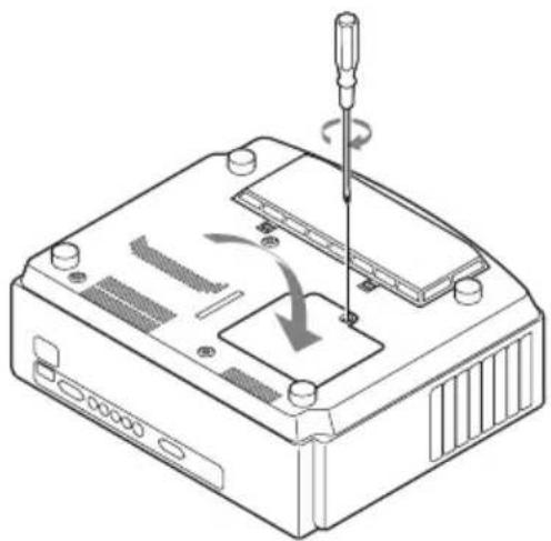
Note
If the lamp cover is not set securely, the power will not turn on.
7 Remove the air filter cover.

8 Remove the air filter.

9 Place a new air filter.

Note
After removing the air filter, do not touch the fan inside the projector.
10 Attach the air filter cover.
11 Wipe dust off the Ventilation holes (intake) with a soft cloth.

Note
The projector will not turn on unless the air filter cover is securely closed.
12 Place the project back on its original position.
13 Turn on the projector, then select the desired setting item on the Setup menu. The menu screen below will be appeared.

14 Select "Yes".

15 Select "OK".
Caution
Do not put your hands into the lamp replacement slot, and do not allow any liquid or other objects into the slot to avoid electrical shock or fire.
Notes
- Be sure to use an LMP-H160 Projector Lamp for replacement. If you use lamps other than the LMP-H160, the projector may malfunction.
- Be sure to turn off the projector and unplug the power cord before replacing the lamp, then check the I/⏻ (On/standby) indicator has already been turned off.
- The projector will not turn on unless the lamp is securely installed in place.
- The projector will not turn on unless the lamp cover are securely closed.
- To cancel a message displayed on the screen, press either the button on the remote control or the one on the control panel on the projector.
Note
The lamp contains mercury. The disposal rules for used fluorescent tubes depend on where you live. Follow the waste disposal policy in your area.
Replacing the Air Filter
When “Please replace the filter.” appears on the screen, you should replace the air filter. The air filter should be replaced every 1,500 hours. This value varies depending on the environment or how the projector is used. 1,500 hours are approximate.
Notes
- For details on how to attach and remove the air filter, see “Replacing the Lamp and the Air Filter and cleaning the Ventilation holes (intake)” Steps 7 to 11. ( page 56)
- When you remove the air filter, be careful not to let any dust fall into the projector.
- Replacing the air filter is crucial to maintain the good performance of the projector or to prevent malfunction to it. When a warning message for replacing the air filter appears, replace the air filter immediately.
Fitting the lens cap
When fitting the lens cap onto the lens, position the lens cap so that the concave on the side of the lens cap will fit the zoom lever, as shown in the illustration.

Note
The lens cap will not fit if the position is not set correctly.
Cleaning and the Screen of the Projector
Cleaning the lens
The lens surface is especially treated to reduce reflection of light.
As incorrect maintenance may impair the performance of the projector, take care with respect to the following:
- Wipe the lens gently with a soft cloth such as a cleaning cloth or glass cleaning cloth.
- Stubborn stains may be removed with a soft cloth such as a cleaning cloth or glass cleaning cloth lightly dampened with water.
- Never use solvent such as alcohol, benzene or thinner, or acid, alkaline or abrasive detergent, or chemical cleaning cloth, as they will damage the lens surface.
Cleaning the cabinet
- To remove dust from the cabinet, wipe gently with a soft cloth. If dust is persistent, wipe with a soft cloth slightly moistened with a diluted mild detergent solution.
- Never use any type of abrasive pad, alkaline/acid cleaner, scouring powder, or volatile solvent, such as alcohol, benzene, thinner or insecticide.
- Using such materials or maintaining prolonged contact with rubber or vinyl materials may result in damage to the screen surface and cabinet material.
Black points and bright points (red, blue, or green) on the screen
The projector is manufactured using high-precision technology.
You may, however, see tiny black points and/or bright points (red, blue, or green) that continuously appear on the projector.
This is a normal result of the manufacturing process and does not indicate a malfunction.
Specifications
System
Projection system
3LCD panel, 1 lens, projection system
LCD panel 0.73-inch (18.5 mm) TFT LCD panel 2,764,800 pixels (921,600 pixels × 3)
Lens 1.6 times zoom lens (manual)
f=21.3 mm to 34.1 mm/
F2.4 to F3.1
Lamp 165 W Ultra High Pressure Lamp
Projection picture size
40 inches to 200 inches (measured diagonally)
Color system NTSC 3.58/PAL/SECAM/NTSC4.43/
PAL-M/PAL-N/PAL60 system, switched automatically/ manually (PAL60 system not switched manually)
Acceptable video signals
15 kHz RGB/component
50/60 Hz, Progressive
component 50/60 Hz, DTV
(480/60i, 576/50i, 480/60p,
576/50p, 720/60p, 720/50p,
1080/60i, 1080/50i, 1080/48i),
1080/60p (HDMI input only),
1080/50p (HDMI input only),
1080/24p (HDMI input only),
Composite video, Y/C video
Acceptable computer signals
fH: 19 kHz to 72 kHz
fV: 48 Hz to 92 Hz
Maximum resolution 1920× 1080
(HDMI input only)
For details, see "Preset Signals".
( page 61)
Input
Video input VIDEO: phono type
Composite video: 1 Vp-p±2 dB sync negative (75 ohms terminated)
Y (luminance): 1 Vp-p±2 dB sync negative (75 ohms terminated)
C (chrominance): burst
0.286 Vp-p ±2 dB (NTSC)
(75 ohms terminated), or burst 0.3 Vp-p±2 dB (PAL) (75 ohms terminated)
Y Pb/Cb PR/CR
Component: phono type
Y with Sync: 1 Vp-p±2dB sync
negative (75 ohms terminated)
P B/CB : 0.7 Vp-p±2dB (75 ohms terminated)
P R/CR : 0.7 Vp-p±2 dB (75 ohms terminated)
HDMI Digital RGB/Y C B (PB) CR (PR)
INPUT A HD D-sub 15-pins
Analog RGB/component:
R / CR(Pr):0.7Vp - p± 2dB
(75 ohms terminated)
G: 0.7 Vp-p±2 dB
(75 ohms terminated)
G with sync/Y: 1 Vp-p±2 dB
sync negative (75 ohms terminated)
B / CB(PB) : 0.7Vp - p± 2 dB
(75 ohms terminated)
SYNC/HD: Composite sync
input: TTL level, positive/negative
Horizontal sync input: TTL
level, positive/negative
VD: Vertical sync input: TTL
level, positive/negative
REMOTE RS-232C: D-sub 9-pin (female)
General
Dimensions 370 mm × 119 mm × 320 mm
(excluding (145 / 8× 43 / 4× 125 / 8 inches)
projections) (w/h/d)
Mass VPL-AW15 : Approx. 6.0 kg (13 lb 04 oz)
VPL-AW10: Approx. 5.8 kg
(12 lb 13 oz)
Power requirements
100 V - 240 V, 2.65 A - 1.05 A, 50/60 Hz
Power consumption
Max. 265 W
Standby mode: 7 W
Standby mode (low): 0.5 W
Operating temperature
5°C to 35°C (41°F to 95°F)
Operating humidity
35% to 85% (no condensation)
Storage temperature
-20°C to +60°C (-4°F to +140°F)
Storage humidity
10% to 90%
Supplied accessories
Remote control
RM-PJAW15 (1)
(VPL-AW15 only)
RM-PJAW10 (1)
(VPL-AW10 only)
Size AA (R6) batteries (2)
AC power cord (1)
Air filter (for replacement) (1)
Lens Cap (1)
Operating Instructions (1)
Design and specifications are subject to change without notice.
Optional accessories
Projector Lamp LMP-H160 (for replacement)
Projector Suspension Support PSS-H10, PSS-610
Warning on power connection
Use a proper power cord for your local power supply.
| The United States, Canada | Continental Europe | UK, Ireland, Australia, New Zealand | Japan China | ||
| Plug type YP-3 | YP-12A * YP-359 | VM0722 | |||
| Female end YC-13 | YC-13D VM0303B | YC-13 VM0724 | |||
| Cord type SVT H | 05VV-F CEE (13) | 53 | rd (OC) | VCTF 227 IEC | 53 (RVV) |
| Rated Voltage & Current | 10A/125V | 10A/250V | 10A/250V | 12A/125V | 10A/250V |
| Safety approval | UL/CSA | VDE | VDE | DENANHO | CCC |
* Use a rated plug that complies with the regulation of each country/region and the specifications.
Preset Signals
The following table shows the signals and video formats which you can project using this unit.
When a signal other than the preset signal shown below is input, the picture may not be displayed properly.
| Memory No. | Preset signal (Resolution) | fH (kHz) | fV (Hz) | Sync H Size | ||
| 1 | VIDEO/60 | 60 Hz | 15.734 | 59.940 | - | - |
| 2 | VIDEO/50 | 50 Hz | 15.625 | 50.000 | - | - |
| 3 | 480/60i | DTV 480/60i (720 × 480i) | 15.734 | 59.940 | SonG/Y or composite sync | - |
| 4 | 576/50i | DTV 576/50i (720 × 576i) | 15.625 | 50.000 | SonG/Y or composite sync/composite video | - |
| 5 | 480/60p | 480/60p (720 × 480p) (Progressive NTSC) | 31.470 | 60.000 | SonG/Y | - |
| 6 | 576/50p | 576/50p (720 × 576p) (Progressive PAL) | 31.250 | 50.000 | SonG/Y | - |
| 7 | 1080/60i | 1035/60i (1920 × 1035i), 1080/60i (1920 × 1080i) | 33.750 | 60.000 | SonG/Y | - |
| 8 | 1080/50i | 1080/50i (1920 × 1080i) | 28.130 | 50.000 | SonG/Y | - |
| Memory No. | Preset signal (Resolution) | fH (kHz) | fV (Hz) | Sync | H Size | |
| 9 1080 | 0/24PsF 1080/48i(1920 × 1080i) | 27.000 48 | 0.000 Son | G/Y - | ||
| 10 720 | 60p 720/60p | (1280 × 720p) | 45.000 60 | 0.000 Son | G/Y - | |
| 11 720 | 50p 720/50p | (1280 × 720p) | 37.500 50 | 0.000 Son | G/Y - | |
| 12 1080 | 60p 1080/60p | (1920 × 1080p) | 67.500 60 | 0.000 -- | ||
| 13 1080 | 50p 1080/50p | (1920 × 1080p) | 56.260 50 | 0.000 -- | ||
| 14 1080 | 24p 1080/24p | (1920 × 1080p) | 26.973 23 | 3.976 -- | ||
| 21 640 | × 350 VGA-1 | (VGA350) 31.469 | 70.086 H-pos, V-neg | 800 | ||
| 22 VESA 85 | (VGA350) | 37.861 85 | 0.080 H-pos, V-neg 832 | |||
| 23 640 | × 400 NEC P | C98 24.823 56.416 | H-neg, V-neg 848 | |||
| 24 VGA-2 (TEXT)/ | VESA70 | 31.469 70 | 0.086 H-neg, V-pos 800 | |||
| 25 VESA 85 | (VGA400) | 37.861 85 | 0.080 H-neg, V-pos 832 | |||
| 26 640 | × 480 VESA | 60 31.469 59.940 H-neg, V-neg 800 | ||||
| 27 Mac 13 | 35.000 66.667 H-neg, V-neg 864 | |||||
| 28 VESA 72 37.861 | 72.809 H-neg, V-neg 832 | |||||
| 29 VESA 75 (IBM | M3) | 37.500 75 | 0.000 H-neg, V-neg 840 | |||
| 30 VESA 85 (IBM | M4) | 43.269 85 | 0.008 H-neg, V-neg 832 | |||
| 31 | 800 × 600 | VESA 56 | 35.156 | 56.250 | H-pos, V-pos | 1024 |
| 32 VESA 60 37.879 | 60.317 H-pos, V-pos | 1056 | ||||
| 33 VESA 72 48.077 | 72.188 H-pos, V-pos | 1040 | ||||
| 34 VESA 75 (IBM | M5) | 46.875 75 | 0.000 H-pos, V-pos | 1056 | ||
| 35 VESA 85 53.674 | 85.061 H-pos, V-pos | 1048 | ||||
| 36 | 832 × 624 | Mac 16 | 49.724 | 74.550 | H-neg, V-neg | 1152 |
| 37 | 1024 × 768 | VESA 60 | 48.363 | 60.004 | H-neg, V-neg | 1344 |
| 38 VESA 70 56.476 | 70.069 H-ncg, V-ncg | 1328 | ||||
| 39 VESA 75 60.023 | 75.029 H-pos, V-pos | 1312 | ||||
| 45 | 1280 × 960 | VESA 60 | 60.000 | 60.000 | H-pos, V-pos | 1800 |
| 47 | 1280 × 1024 | VESA 60 | 63.974 | 60.013 | H-pos, V-pos | 1696 |
| Memory No. | Preset signal (Resolution) | fH (kHz) | fV (Hz) Sync | H Size | ||
| 50 140 | 0 × 1050 SXG | A + 65.317 59.978 H | H-neg, V-pos | 1864 | ||
| 55 | 1280 × 768 | 1280 × 768/60 | 47.776 | 59.870 | H-neg, V-pos | 1664 |
| 56 | 1280 × 720 | 1280 × 720/60 | 44.772 | 59.855 | H-neg, V-pos | 1664 |
Preset memory numbers for each input signal
Analog signal
| Signal Preset memory number | |
| Video signal (VIDEO INPUT and S VIDEO INPUT connectors) | 1, 2 |
| Component signal (INPUT A and Y PB/CB PR/ CR connectors) | 3 to 11 |
| Video GBR signal (INPUT A connector) 3 to 11 | |
| Computer signal (INPUT A connector) 21 to 39, 55 to 56 | |
Digital signal
| Signal Preset memory number | |
| Component signal (HDMI connector) 3 to 8, 10 to | 14 |
| Video GBR signal (HDMI connector) 3 to 8, 10 to | 14 |
| Computer signal (HDMI connector) 10 to 13*, 26, | 32, 36, 37, 45, 47, 50, 55 |
* Some digital signals input from computers may be displayed as preset memory number of DTV signal (Component or Video GBR signal).
Input Signals and Adjustable/Setting Items
The items in the menus available to adjust differ depending on the input signal. The following tables indicate them.
The items that cannot be adjusted are not displayed in the menu.
| Item Input signal | ||||
| Video or S-Video (Y/C) | Component Video | GBR Computer | ||
| Advanced Iris ● | ● | ● | ● | |
| Lamp Control ● | ● | ● | ● | |
| Contrast ● | ● | ● | ● | |
| Brightness ● | ● | ● | ● | |
| Color | ●(except for B & W) | ● | ● | - |
| Hue ● | (NTSC3.58/NTSC4.43 only, except for B & W) | ● | ● | - |
| Color Temp. ● | ● | ● | ● | |
| Sharpness ● | ● | ● | - | |
| NR ● | ● | (preset memory numbers 3, 4, 7, 8, 9 only) | ●(preset memory numbers 3, 4, 7, 8, 9 only) | - |
| DDE | ● | ●(preset memory numbers 3, 4, 7, 8, 9 only) | ●(preset memory numbers 3, 4, 7, 8, 9 only) | - |
| Black Level Adj. | ● | ● | ● | - |
| Gamma Correction | ● | ● | ● | ● |
| RCP | ● | ● | ● | ● |
● : Adjustable/can be set
- : Not adjustable/cannot be set
Screen menu
| Item Input signal | Video or S-Video (Y/C) | Component Video | GBR Computer | |
| Wide Mode ● | ● | ● | ● | 2 * |
| Over Scan - ● | ● | - | ||
| Screen Area *1 | - ● | (preset memory numbers 10, 11 only) | ●(preset memory numbers 10, 11 only) | - |
| V Position*3 | ● | ● | ● | ● |
| V Size*3 | ● | ● | ● | - |
| APA | - | - | - | ●*4 |
| Phase | - | - | - | ●*4 |
| Pitch | - | - | - | ●*4 |
| Shift | - ● | ● | ● |
● : Adjustable/can be set
- : Not adjustable/cannot be set
*1: This item is effective only when “Over Scan” is set to “On” in the Screen menu. It cannot be set at preset signal 1920 × 1080 .
*2: If the input signal is from a computer, the setting cannot be made when the aspect ratio is 16:9 or wider.
*3: The setting can be made only when “Zoom” is selected in “Wide Mode”.
*4: The setting can be made only for analog signal.
Note
When connecting a cable such as an HDMI cable, etc., check the type of the signal in the Information ☐ Menu ( page 50) and Digital signal ( page 63), and check items that are adjustable/can be set.
Ceiling Installation
Use the PSS-H10 or PSS-610 Projector Suspension Support when you install the projector on a ceiling. The projection distances for ceiling installation are shown below.
When Using the PSS-H10 Projector Suspension Support
a: Distance between the screen and the installation hole at the ceiling side of the ceiling mount unit (front side)
x: Distance between the ceiling and the center of the screen such that the picture will not be truncated or blocked

When using the 16:9 aspect ratio screen
Unit: mm (inches)
| Screen Size(inches) | 40 60 70 | 80 100 12 | 0 140 160 | 180 200 | |||||||
| (mm) | 1016 1524 | 1778 203 | 32 2540 3 | 048 3556 | 4064 457 | 2 5080 | |||||
| a | M i n iDistance | h266m (49 7/8) | 1864 (73 1/2) | 2163 (85 1/4) | 2462(97) | 3061 (120 5/8) | 3659 (144 1/8) | 4257 (167 5/8) | 4855 (191 1/4) | 5453 (214 3/4) | 6051 (238 3/8) |
| MaximumDistance | 1999 (78 3/4) | 2964 (116 3/4) | 3446 (135 3/4) | 3929 (154 3/4) | 4894 (192 3/4) | 5858 (230 3/4) | 6823 (268 3/4) | 7788 (306 3/4) | 8753 (344 3/4) | 9717 (382 5/8) | |
| x | M i n iDistance | h249um (9 7/8) | 373 (14 3/4) | 436 (17 1/4) | 498 (19 5/8) | 622 (241/2) | 747 (29 1/2) | 871 (34 3/8) | 996 (39 1/4) | 1120 (44 1/8) | 1245(49) |
| MaximumDistance | 562 (22 1/4) | 724 (28 1/2) | 805 (31 3/4) | 886 (34 7/8) | 1047 (411/4) | 1209 (47 5/8) | 1371(54) | 1533 (60 3/8) | 1695 (66 3/4) | 1856 (73 1/8) | |
To calculate the installation measurements (SS: Screen Size)
a (minimum) = 29.909 (1 3/16 ) × SS + 69.614 (2 3/4 )
a (maximum) = 48.239 (115 / 16) × SS + 69.631(23 / 4)
x (minimum) = 6.223 ( 1/4 ) × SS
x (maximum) = 8.0899 ( 11 / 32 ) × SS + 238.5 (9 1 / 2 )
When using the 4:3 aspect ratio screen
Unit: mm (inches)
| Screen Size (inches) | 40 60 70 | 80 100 12 | 0 140 160 | 180 200 | |||||||
| (mm) | 1016 1524 | 1778 203 | 32 2540 3 | 048 3556 | 4064 4572 | 5080 | |||||
| a | M i n i Distance | h634u m (601/2) | 2266 (891/4) | 2632 (1033/4) | 2998 (1181/8) | 3731 (147) | 4463 (1753/4) | 5195 (2045/8) | 5927 (2333/8) | 6659 (2621/4) | 7391 (2911/8) |
| Maximum Distance | 2431 (953/4) | 3612 (1421/4) | 4203 (1651/2) | 4793 (1883/4) | 5974 (2351/4) | 7155 (2813/4) | 8336 (3281/4) | 9517 (3743/4) | 10698 (4211/4) | 11879 (4673/4) | |
| x | M i n i Distance | h605u m (12) | 457 (18) | 533 (21) | 609 (24) | 762 (30) | 914 (36) | 1066 (42) | 1219 (48) | 1371 (54) | 1523 (60) |
| Maximum Distance | 635 (25) | 833 (327/8) | 932 (363/4) | 1031 (405/8) | 1229 (483/8) | 1427 (561/4) | 1625 (64) | 1823 (717/8) | 2021 (7919/32) | 2219 (873/8) | |
To calculate the installation measurements (SS: Screen Size)
a (minimum) = 36.609 (11 / 2)× SS + 69.614(23 / 4)
a (maximum) = 59.045 (23 / 8) × SS + 69.631 (23 / 4)
x (minimum) = 7.617 ( 5/16 ) × SS
x (maximum) = 9.902 ( 13 / 32 ) × SS + 238.5 ( 91 / 2 )
Attaching the PSS-H10 projector suspension support
For details on installation on a ceiling, refer to the Installation manual for Dealers of the PSS-H10. Make sure to consult with a qualified Sony personnel for installation.
The installation measurements are shown below when installing the projector on a ceiling using the PSS-H10.
Top view
Install the projector so that the center of the lens is parallel to the center of the screen.

Front view

*d 63.5 (2 1/2) (VPL-AW15) 68 (2 3/4) (VPL-AW10)
Side view

When Using the PSS-610 Projector Suspension Support
a: Distance between the screen and the installation hole of the upper ceiling mount bracket (front side)
b: Distance from the ceiling to the bottom surface of the unit
x: Distance between the ceiling and the center of the screen such that the picture will not be truncated or blocked
PSS-610 Projector Suspension Support (not supplied)
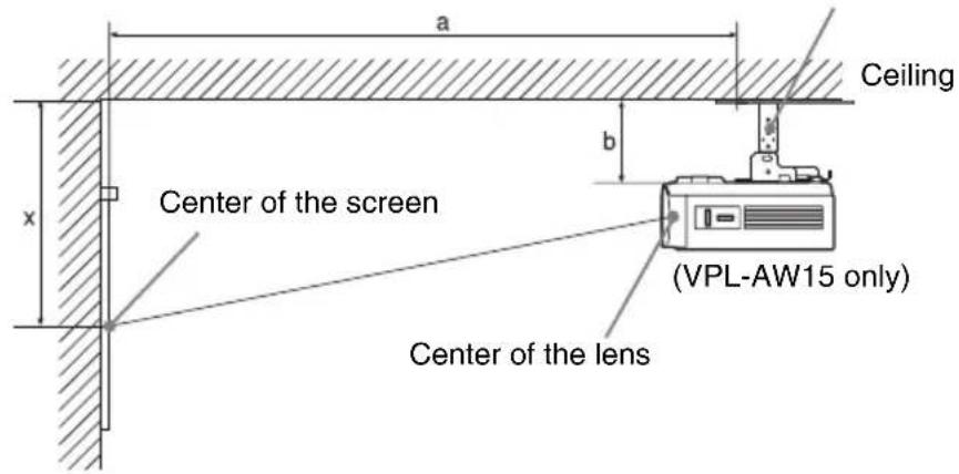
When using the 16:9 aspect ratio screen
Unit: mm (inches)
| Screen Size (inches) | 40 60 70 | 80 100 12 | 20 140 160 | 180 200 | |||||||
| (mm) | 1016 1524 | 1778 203 | 2 2540 30 | 48 3556 | 4064 4572 | 5080 | |||||
| a | M i n i Distance | h25 u m (49 3/8) | 1850 (72 7/8) | 2149 (84 5/8) | 2448 (96 1/2) | 3046 (11915/16) | 3644 (143 1/2) | 4242 (167 1/8) | 4841 (190 5/8) | 5439 (214 1/4) | 6037 (237 3/4) |
| Maximum Distance | 1987 (78 1/4) | 2951 (116 1/4) | 3434 (135 1/4) | 3916 (154 1/4) | 4881 (192 1/4) | 5846 (230 1/4) | 6811 (268 1/4) | 7775 (306 1/4) | 8740 (344 1/4) | 9705 (382 1/4) | |
| x | M i n i Distance | h249u m (9 7/8) | 373 (14 3/4) | 436 (17 1/4) | 498 (19 5/8) | 622 (24 1/2) | 747 (29 1/2) | 871 (34 3/8) | 996 (39 1/4) | 1120 (44 1/8) | 1245(49) |
| Maximum Distance | 387+b (15 1/4+b) | 549+b (21 5/8+b) | 630+b (24 7/8+b) | 711+b (28+b) | 872+b (34 3/8+b) | 1034+b (40 3/4+b) | 1196+b (47 1/8+b) | 1358+b (53 1/2+b) | 1520+b (59 7/8+b) | 1681+b (66 1/4+b) | |
| b | 150, 175, 200, 250, 275, 300 mm ( 6, 7, 7 7/8, 9 7/8, 10 7/8, 11 7/8 inches) adjustable when using PSS-610 | ||||||||||
To calculate the installation measurements (SS: Screen Size)
a (minimum) = 29.909 (1 3 / 16 ) × SS + 57.114 (2 1 / 4 )
a (maximum) = 48.239 (1 15 / 16 ) × SS + 57.131 (2 1 / 4 )
x (minimum) = 6.223 (1 / 4) × SS
x (maximum) = 8.0899 ( 11 / 32 ) × SS + 63.5 ( 21 / 2 ) + b
When using the 4:3 aspect ratio screen
Unit: mm (inches)
| Screen Size (inches) | 40 60 70 | 80 100 12 | 0 140 160 | 180 200 | |||||||
| (mm) | 1016 1524 | 1778 203 | 32 2540 3 | 048 3556 | 4064 4572 | 5080 | |||||
| a | M i n i Distance | h521 m (60) | 2254 (88 3 /4) | 2620 (103 1 /4) | 2986 (117 5 /8) | 3718 (146 1 /2) | 4450 (175 1 /4) | 5182 (204 1 /8) | 5915 (233) | 6647 (261 3 /4) | 7379 (290 5 /8) |
| Maximum Distance | 2419 (95 1 /4) | 3600 (141 3 /4) | 4190 (165) | 4781 (188 1 /4) | 5962 (234 3 /4) | 7143 (281 1 /4) | 8323 (327 3 /4) | 9504 (374 1 /4) | 10685 (420 3 /4) | 11866 (467 1 /4) | |
| x | M i n i Distance | 305u m (12) | 457 (18) | 533 (21) | 609 (24) | 762 (30) | 914 (36) | 1066 (42) | 1219 (48) | 1371 (54) | 1523 (60) |
| Maximum Distance | 460+b (18 1 /8+b) | 658+b (26+b) | 757+b (29 7 /8+b) | 856+b (33 3 /4+b) | 1054+b (41 1 /2+b) | 1252+b (49 3 /8+b) | 1450+b (57 1 /8+b) | 11648+b (458 3 /4+b) | 1846+b (72 3 /4+b) | 2044+b (80 1 /2+b) | |
| b | 150, 175, 200, 250, 275, 300 mm (6, 7, 7 7 /8, 9 7 /8, 10 7 /8, 11 7 /8 inches) adjustable when using PSS-610 | ||||||||||
To calculate the installation measurements (SS: Screen Size)
a (minimum) = 36.609 (11/2) × SS + 57.114(21/4)
a (maximum) = 59.045 (23 / 8)× SS + 57.131(21 / 4)
x (minimum) = 7.617 ( 5/16 ) × SS
x (maximum) = 9.902 ( 13 / 32 ) × SS + 63.5 ( 21 / 2 ) + b
Attaching the PSS-610 projector suspension support
For details on installation on a ceiling, refer to the Installation manual for Dealers of the PSS-610. Make sure to consult with a qualified Sony personnel for installation.
The installation measurements are shown below when installing the projector on a ceiling using the PSS-610.
Top view
Install the projector so that the center of the lens is parallel to the center of the screen.

Front view
Distance between the ceiling and the surface of the mount bracket
Using adjustment pipe (b): 150/175/200 mm (6 / 7 / 7 7 /8 inches)
Using adjustment pipe (c): 250/275/300 mm ( 97/8 / 107/8 / 117/8 inches)

*d
63.5 (21 / 2) (VPL-AW15)
68 (23 / 4) (VPL-AW10)
Side view

Index
A
Adjust Signal
Phase 45
Pitch 45
Shift 45
Adjuster 24
Adjusting
picture position 21
picture quality ....32
Advanced Iris 41
Auto Input Search 48
B
Background 48
Black Level Adj. 42
Blanking 49
Brightness 41
C
Ceiling Installation 66
Cinema Black Pro ....41
Color System 47
Color Temp. 41
Connecting
Computer 20
Video equipment 17
Contrast 41
Cooling Setting 46
F
fH 50
fV 50
G
Gamma Correction 42
H
HDMI 18
Hue 41
|
Image Flip 49
Input-A Signal Sel. 47
L
Lamp Timer 50
Language 46
Location of Controls
Front/Right side 8
Rear/Bottom 9
M
Menu
Advanced Picture 43
Function 48
Information 50
Installation 49
Picture 40
Screen 44
Setup 46
Messages
Caution 54
Warning 54
N
NR 42
0
Over Scan 44
P
Picture Mode
CINEMA 31
Cinema 40
DYNAMIC 31
Dynamic 40
STANDARD 31
Standard 40
USER 31
User 40
Precautions 7
Preset Memory 50
Preset Signals 61
R
RCP 43
Remote control
inserting the batteries 11
location of controls 10
Reset
resettable items 39
resetting the items 39
s
Screen Area 45
Selecting the menu language 25
Sharpness 42
Specifications 59
Standby Mode 46
Status 46
Supplied accessories 11
T
Troubleshooting 51
V
V Keystone 49
W
WIDE MODE 28
Wide Mode
Full 44
Full 1 44
Full 2 44
Normal 44
Wide Zoom 44
Zoom 44

http://www.sony.net/

Printed on 70% or more recycled paper.



- WARNING
- FOR CUSTOMERS IN THE USA
- DECLARATION OF CONFORMITY
- DISPOSAL OF USED LAMP
- FOR CUSTOMERS IN THE UNITED STATES
- FOR CUSTOMERS IN EUROPE
- TRADEMARK INFORMATION
- FOR CUSTOMERS IN CANADA
- CAUTION
- DISPOSAL OF OLD ELECTRICAL & ELECTRONIC EQUIPMENT (APPLICABLE IN THE EUROPEAN UNION AND OTHER EUROPEAN COUNTRIES WITH SEPARATE COLLECTION SYSTEMS)
- FOR CUSTOMERS IN TAIWAN ONLY
- TABLE OF CONTENTS
- LOCATION OF CONTROLS
- CONNECTIONS AND PREPARATIONS
- PROJECTING
- USING THE MENUS
- OTHERS
- PRECAUTIONS
- ON SAFETY
- ON PREVENTING INTERNAL HEAT BUILD-UP
- ON REPACKING
- CHECKING THE MODEL NAME OF THE PROJECTOR
- FRONT/SIDE
- REAR/BOTTOM
- REMOTE CONTROL
- UNPACKING
- INSERTING THE BATTERIES INTO THE REMOTE CONTROL
- CAUTION ABOUT HANDLING THE REMOTE CONTROL
- STEP 1: INSTALLING THE PROJECTOR
- BEFORE SETTING UP THE PROJECTOR
- UNSUITABLE INSTALLATION
- POORLY VENTILATED LOCATION
- HOT AND HUMID
- LOCATIONS SUBJECT TO DIRECT COOL OR WARM AIR FROM AN AIR-CONDITIONER
- NEAR A HEAT OR SMOKE SENSOR
- VERY DUSTY AND EXTREMELY SMOKY LOCATIONS
- INSTALL IN A LOCATION AWAY FROM WALLS
- IMPROPER USE
- BLOCKING THE VENTILATION HOLES
- TIP
- TILTING FRONT/REAR AND LEFT/RIGHT
- WHEN INSTALLING THE UNIT AT ALTITUDES
- POSITIONING THE PROJECTOR AND A SCREEN
- DETERMINE THE INSTALLATION POSITION OF THE PROJECTOR AND SCREEN
- WHEN USING THE 16:9 ASPECT RATIO SCREEN
- WHEN USING THE 4:3 ASPECT RATIO SCREEN (PROJECTING A 4:3 PICTURE)
- POSITION THE PROJECTOR SO THAT THE LENS IS PARALLEL TO THE SCREEN
- PROJECT AN IMAGE ON THE SCREEN AND ADJUST THE PICTURE SO THAT IT FITS THE SCREEN. ( PAGE 21)
- NOTE
- STEP 2: CONNECTING THE PROJECTOR
- WHEN MAKING CONNECTIONS, BE SURE TO DO THE FOLLOWING
- CONNECTING TO A VCR
- TO CONNECT TO A DVD PLAYER/RECORDER AND BLU-RAY DISC PLAYER EQUIPPED WITH HDMI OUTPUT
- NOTES
- TO CONNECT TO A VCR EQUIPPED WITH THE S VIDEO CONNECTOR OR VIDEO CONNECTOR
- CONNECTING TO A COMPUTER
- STEP 3: ADJUSTING THE PICTURE POSITION
- AFTER CONNECTING THE AC CORD TO THE EQUIPMENT, PLUG THE AC CORD INTO A WALL OUTLET
- PRESS THE I/⏻ (ON/STANDBY) SWITCH TO TURN ON THE PROJECTOR
- TURN ON THE EQUIPMENT CONNECTED TO THE PROJECTOR
- PRESS INPUT TO PROJECT THE PICTURE ON THE SCREEN
- TIPS
- MOVE BOTH LENS SHIFT DIALS (VPL-AW15 ONLY) TO ADJUST THE PICTURE POSITION
- TO ADJUST THE HORIZONTAL POSITION
- TO ADJUST THE VERTICAL POSITION
- TO ADJUST THE TILT OF THE INSTALLATION SURFACE
- STEP 4: SELECTING THE MENU LANGUAGE
- PRESS MENU
- PRESS ↑/↓ TO SELECT THE SETUP MENU, AND PRESS → OR
- PRESS ↑/↓ TO SELECT "LANGUAGE," AND PRESS → OR
- PRESS ↑/↓/←/→ TO SELECT A LANGUAGE, AND PRESS ⊕
- TO CLEAR THE MENU
- PROJECTING THE PICTURE ON THE SCREEN
- TURNING OFF THE POWER
- PRESS THE I/⏻ (ON/STANDBY) SWITCH
- PRESS THE I/⏻ (ON/STANDBY) SWITCH AGAIN BEFORE THE MESSAGE DISAPPEARS
- CONFIRM THAT THE FAN STOPS RUNNING AND THE I/⏻ (ON/STANDBY) INDICATOR LIGHTS IN RED
- SELECTING THE WIDE SCREEN MODE
- PRESS WIDE MODE
- WIDE ZOOM
- NORMAL
- FULL
- ZOOM
- FULL 1 (WHEN THE PC SIGNAL IS INPUT)
- FULL 2 (WHEN THE PC SIGNAL IS INPUT)
- NOTES ON SELECTING THE WIDE SCREEN MODE
- SELECTING THE PICTURE VIEWING MODE
- DYNAMIC
- STANDARD
- CINEMA
- USER 1, USER 2 AND USER
- ADJUSTING THE PICTURE QUALITY
- PRESS ADJ PIC
- MAKE THE SETTING OR ADJUSTMENT ON AN ITEM
- ADJUSTING THE PICTURE USING REAL COLOR PROCESSING (VPL-AW15 ONLY)
- ADJUST THE COLOR OF THE SPECIFIED PORTIONS
- AFTER THE ADJUSTMENT IS COMPLETE, PRESS
- USING OTHER FUNCTIONS
- PRESS PIC MUTING
- PRESS FREEZE
- OPERATION THROUGH THE MENUS
- PRESS ↑/↓ TO SELECT A MENU ITEM, AND PRESS → OR ⊕
- PRESS ↑/↓ TO SELECT AN ITEM YOU WANT TO SET OR ADJUST AND PRESS
- MAKE THE SETTING OR ADJUSTMENT OF AN ITEM
- WHEN CHANGING THE ADJUSTMENT LEVEL
- WHEN CHANGING THE SETTING
- ITEMS THAT CANNOT BE ADJUSTED
- TO RESET THE PICTURE THAT HAS BEEN ADJUSTED
- TO RESET THE ITEMS THAT HAVE BEEN ADJUSTED
- PICTURE MENU
- ADVANCED PICTURE MENU (VPL-AW15 ONLY)
- SCREEN MENU
- SETUP MENU
- FUNCTION MENU
- INSTALLATION MENU
- INFORMATION MENU
- ABOUT THE PRESET MEMORY NO
- TROUBLESHOOTING
- POWER
- PICTURE
- WARNING INDICATORS
- REPLACING THE LAMP AND THE AIR FILTER AND CLEANING THE VENTILATION HOLES (INTAKE)
- PLACE A NEW AIR FILTER
- ATTACH THE AIR FILTER COVER
- WIPE DUST OFF THE VENTILATION HOLES (INTAKE) WITH A SOFT CLOTH
- PLACE THE PROJECT BACK ON ITS ORIGINAL POSITION
- TURN ON THE PROJECTOR, THEN SELECT THE DESIRED SETTING ITEM ON THE SETUP MENU. THE MENU SCREEN BELOW WILL BE APPEARED
- SELECT "YES
- SELECT "OK
- REPLACING THE AIR FILTER
- FITTING THE LENS CAP
- CLEANING AND THE SCREEN OF THE PROJECTOR
- CLEANING THE LENS
- CLEANING THE CABINET
- BLACK POINTS AND BRIGHT POINTS (RED, BLUE, OR GREEN) ON THE SCREEN
- SPECIFICATIONS
- SYSTEM
- INPUT
- GENERAL
- SUPPLIED ACCESSORIES
- OPTIONAL ACCESSORIES
- WARNING ON POWER CONNECTION
- PRESET SIGNALS
- PRESET MEMORY NUMBERS FOR EACH INPUT SIGNAL
- ANALOG SIGNAL
- DIGITAL SIGNAL
- INPUT SIGNALS AND ADJUSTABLE/SETTING ITEMS
- CEILING INSTALLATION
- WHEN USING THE PSS-H10 PROJECTOR SUSPENSION SUPPORT
- WHEN USING THE 4:3 ASPECT RATIO SCREEN
- ATTACHING THE PSS-H10 PROJECTOR SUSPENSION SUPPORT
- TOP VIEW
- FRONT VIEW
- SIDE VIEW
- WHEN USING THE PSS-610 PROJECTOR SUSPENSION SUPPORT
- ATTACHING THE PSS-610 PROJECTOR SUSPENSION SUPPORT
- INDEX
- A
- B
- C
- F
- G
- H
- L
- M
- N
- P
- R
- S
- T
- V
- W
Brand : SONY
Model : VPL-AW15S
Category : Projector