
UHB 51-1500 - Floor Cleaner NILFISK - Free user manual and instructions
Find the device manual for free UHB 51-1500 NILFISK in PDF.

| Product type | Single-brush floor cleaner |
| Brand | Nilfisk |
| Model | UHB 51-1500 |
| Power supply | 36 V (lead-acid or AGM batteries) |
| Disc motor | 1.5 kW, 55 A |
| Traction motor | 0.37 kW (0.5 hp) |
| Disc diameter | 51 cm |
| Disc rotation speed | 1,500 rpm |
| Disc pressure | Automatic, adjustable |
| Forward speed | 0 to 73 m/min |
| Reverse speed | 0 to 52 m/min |
| Vibration level | <7.6 mm/s |
| Sound level | 68 dBA |
| On-board charger | Standard 36 V, 21 A |
| Dimensions (L x W x H) | 127 x 58 x 105 cm |
| Weight (without batteries) | 79 kg |
| Efficiency | 2,230 m²/h |
| Polished strip width | 51 cm |
| Wheels | 4 cm x 20 cm |
| Usage | Commercial (hotels, schools, hospitals, factories, stores, offices) |
| Batteries | 3 x 12 V, 185 Ah or 234 Ah AGM |
| Dust bag | Yes, part number 54195A |
| Maintenance | Charge batteries after use, check bags and skirt, lubricate annually |
| Safety | Use protection, avoid flammable products, do not smoke near batteries |
| Spare parts | Discs, bags, brushes, batteries; use genuine Nilfisk parts |
| Warranty | Void if non-OEM parts used |
Frequently Asked Questions - UHB 51-1500 NILFISK
User questions about UHB 51-1500 NILFISK
0 question about this device. Answer the ones you know or ask your own.
Ask a new question about this device
Download the instructions for your Floor Cleaner in PDF format for free! Find your manual UHB 51-1500 - NILFISK and take your electronic device back in hand. On this page are published all the documents necessary for the use of your device. UHB 51-1500 by NILFISK.
USER MANUAL UHB 51-1500 NILFISK
Safety Instructions 3
Know Your Machine 4
Introduction 5
Parts and Service 5
Nameplate 5
Uncrating the Machine 5
Preparing the Machine for Use 5
Servicing Batteries 5
Battery Installation 7
7
Dust Bag Installation 7
Adjusting Pad Pressure 7
Maintenance 8
Maintenance Schedule 8
Battery Maintenance 8
Specifications 8
Troubleshooting 8
Machine Vibration 8
Swirl Marks 8
Reduced Running Time 8
Pad Assist Machine Does Not Pull Itself 8
Section II Parts List 27
IMPORTANT SAFETY INSTRUCTIONS
This machine is only suitable for commercial use, for example in hotels, schools, hospitals, factories, shops and offices other than normal residential housekeeping purposes.
When using this appliance, basic precautions should always be followed, including the following:

WARNING!
To reduce risk of fire, electric shock, injury or property damage, read all instructions before using.
- Do not operate this machine until it is completely assembled. Inspect the machine carefully before operation.
- Machines can cause an explosion when operated near flammable materials and vapors. Do not use this machine with or near fuels, grain dust, solvents, thinners, or other flammable materials.
- Lead acid batteries generate gases which can cause an explosion. Keep sparks and flames away from batteries. Do not smoke around the machine. Charge the batteries only in an area with good ventilation. Make sure that you unplug the AC charger from the wall outlet before disconnecting from the machine.
- Waste Disposal Method: Dispos as hazardous waste. Observe all federal, state and local environmental regulations for acid or lead scrap. Send batteries to lead smelter for reclamation following applicable federal, state and local regulations.
- Working with batteries can be dangerous! Always wear eye protection and protective clothing when working near batteries. Remove all jewelry. Do not put tools or other metal objects across the battery terminals, or the tops of the batteries.
- Using a charger with a damaged power cord could result in an electrocution. Do not use the charger if the power cord is damaged.
- Operating this machine from anywhere other than the back of the machine could result in injury or damage.
- This machine is heavy. Get assistance before attempting to transport or move it. Use two able persons to move the machine on a ramp or incline. Always move slowly. Do not turn the machine on a ramp. If operating machine on a gradient over 2% , do not stop, turn, or park.
- Machines can topple over if guided over the edges of stairs or loading docks and cause injury or damage. Stop and leave this machine only on a level surface. When you stop the machine, turn the key "OFF".
- Alterations or modifications not authorized by the manufacturer voids any and all warranties and liabilities and could result in damage to the machine or injury to the operator or other bystanders.
- Maintenance and repairs performed by unauthorized personnel could result in damage or injury.
- Keep the electrical components of the machine dry. Wipe the machine down after each use. For storage, keep the machine in a dry building.
- Read all machine labels before attempting to operate. Make sure all of the labels and instructional information are attached or fastened to the machine.
- Use only commercially available floor cleaners and waxes intended for machine operation. Do not use flammable materials.
- When cleaning, servicing or maintaining the machine, replacing parts or converting to another function, the power source should be switched off.
- Use of this machine to move other objects or to climb on could result in injury or damage. Do not use this machine as a step or furniture. Do not ride on this machine.
- Your machine warranty will be voided if anything other than Nilfisk parts are used on your machine.
SAVE THESE INSTRUCTIONS
KNOW YOUR MACHINE
1 On/Off Key Switch
2 Pad Power Switch
3 Pad/TraverseSwitches
4 BatteryMeter
5 Hour Meter
6 Battery Charger Indicator
7 Traverse Reverse
8 Traverse Speed Control
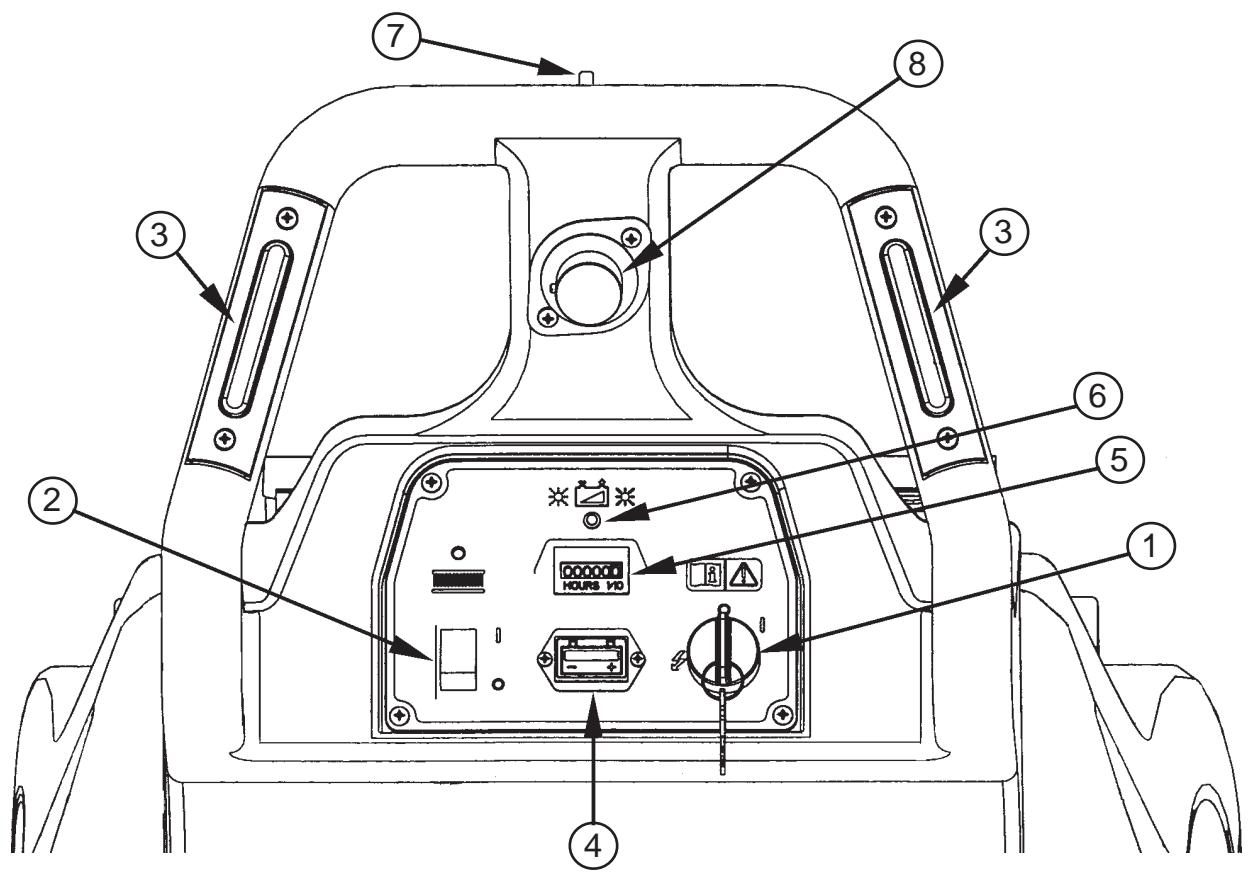
UHB 51-1500
INTRODUCTION
This manual will help you get the most from your Nilfisk floor machine. Read it thoroughly before operating the machine.
This product is intended for commercial use only.
PARTS AND SERVICE
Repairs, when required, should be performed by your Authorized Nilfisk Service Center, who employs factory trained service personnel, and maintains an inventory of Nilfisk original replacement parts and accessories.
Call the Nilfisk dealer named below for repair parts or service. Please specify the Model and Serial Number when discussing your machine.
(Dealer, affix service sticker here.)
NAME PLATE
The Model Number and Serial Number of your machine are shown on the Nameplate on the bottom of the machine. This information is needed when ordering repair parts for the machine. Use the space below to note the Model Number and Serial Number of your machine for future reference.
MODEL NUMBER
SERIAL NUMBER
UNCRATE THE MACHINE
When the machine is delivered, carefully inspect the shipping carton and the machine for damage. If damage is evident, save the shipping carton so that it can be inspected. Contact the Nilfisk Customer Service Department immediately to file a freight damage claim (phone number is provided on the back cover of this manual).
PREPARED THE MACHINE FOR USE
WARNING!
Use extreme caution when working with batteries. Sulfuric acid in batteries can cause severe injury if allowed to contact the skin or eyes. Explosive hydrogen gas is vented from inside the batteries through openings in the battery caps. This gas can be ignited by any arc, spark or flame.
WHENServICINGBATTERIES....
- Remove all jewelry
- Do not smoke
- Wear safety glasses
Work in a well-ventilated area - Do not allow tools to touch more than one battery terminal at a time.
CAUTION!
Electrical components in this machine can be severely damaged if the batteries are not installed and connected properly. Batteries should be installed by your local Nilfisk dealer or by a qualified electricain.
The UHB 51-1500 may be used with three 12 volt 185 amp hour batteries or three 12 volt 234 amp hour AGM batteries.
CAUTION!
The battery charger must be reprogrammed when switching from lead acid to AGM batteries. See the Charger Manual for instructions.
C
1
2
3
4
5
6
D
E
PREPARED THE MACHINE FOR USE
(B)-INSTALLING THE BATTERIES
1 Carefully lift the batteries into the battery tray. Arrange as shown in Figure B.
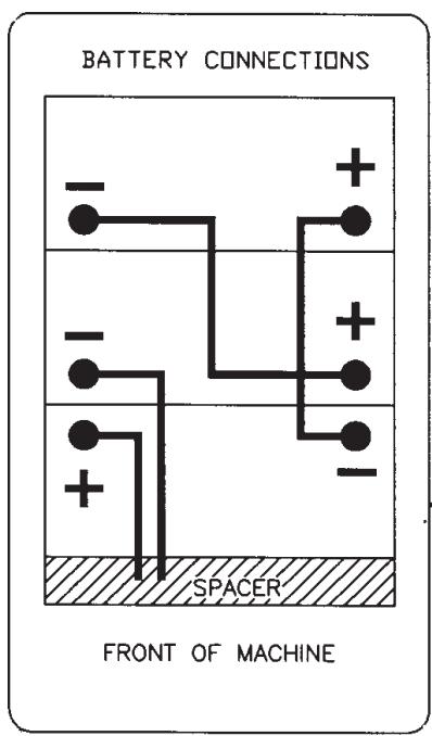
B
2 Make sure the key switch is in the OFF position.
3 Install the battery cables as shown in figure B, with the terminals marked "P" on the positive battery posts and the terminals marked "N" on the negative battery posts. Position the cables so that the caps can be easily removed when it is necessary to add water to the batteries.
4 Tighten the nut on each battery terminal just enough to keep the terminal from being turned on the battery post. Then tighten the nut one more full turn.
5 Coat all the terminals and posts with grease, petroleum jelly or spray-on battery coating (available at most auto parts stores).
6 Put on the black rubber "boots" over each of the terminals and use the plastic tie straps to hold them in place.
7 Join the connector from the battery pack to the connector on the control panel.
8 Reassemble machine.
NOTE: Charge the batteries before using the machine.
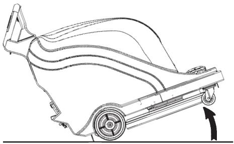
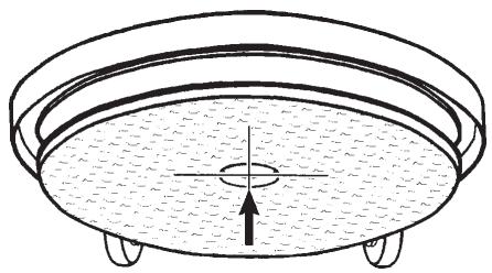
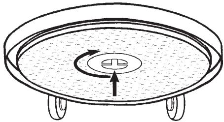
(C)-PAD INSTALLATION
Your local Nilfisk distributor can provide the proper pads and floor finishes for use with this machine.
CAUTION!
Using the wrong kind of pad on this machine can damage the floor. The pad must be centered properly on the pad holder to prevent machine vibration.
For pad installation, follow the steps below (see steps 1 - 6 in Figure C):
1 Turn the key switch off.
2 Put the machine in the position shown, to access the pad retainer.
3 Go to the front of the machine. While holding the pad retainer with one hand, rotate the pad and pad driver counter clockwise to loosen the pad retainer.
4 Remove the old pad and install a new one, being careful to center it on the pad driver.
5 Retighten the pad retainer as tight as possible.
6 Raise the back of the machine to lower the pad housing by lifting as shown.
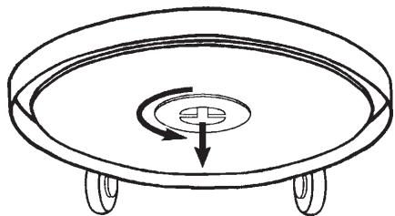
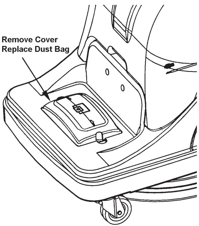
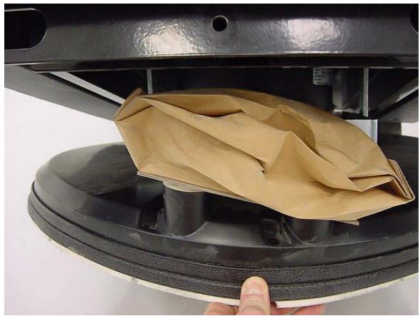
(D)-DUST BAG INSTALLATION
Your local Nilfisk distributor can provide the proper pads and floor finishes for use with this machine.
IMPORTANT!
Install dust collector bag (part number 56201569) on top of control housing (see Figure D). The dust collection system will not operate properly if the collector bag is full or torn.
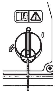
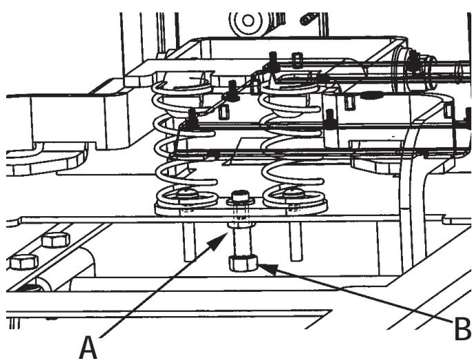
(E)-ADJUSTING PAD PRESSURE
The pad pressure is set at the factory for optimal burnishing with most pad and finish combinations. If unique pad or finish conditions require pad pressure adjustments, adjust by following the procedure below. NOTE: Pad pressure adjustments should be performed by a qualified service technician.
1 Turn key switch off (O).
2 From underneath burnisher, loosen jam nut (A).
3 To decrease pad pressure, turn bolt (B) clockwise.
4 To increase pad pressure, turn bolt (B) counterclockwise.
5 Re-tighten jam nut (A).
MAINTENANCE
MAINTENANCE SCHEDULE
| Maintenance Item | Daily | Monthly | Yearly |
| Charge Batteries | x | ||
| Check/Replace Dust Bags | x | ||
| Check/Replace Skirt | x | ||
| Clean Pad | x | ||
| Lubrication | x | ||
| Check/Service Pad Motor Brushes | x | ||
| Service Drive Motor Brushes | x |
BATTERY MAINTENANCE
Charge the batteries each time the machine is used for 1 hour or longer, or whenever the Battery Meter reads in the red area.
To Charge the Batteries...
1 Remove cover.
2 Plug charger in.
3 Check the fluid level in all battery cells after charging the batteries. Add distilled water, if necessary, to bring the fluid level up to the bottom of the filler tubes.

CAUTION!
To avoid damage to floor surfaces, wipe water and acid from the top of the batteries after charging.

CAUTION!
Acid can spill onto the floor if the batteries are overfilled.
IMPORTANT
Motor damage resulting from failure to service carbon brushes is not covered under warranty. See the Limited Warranty statement.
SPECIFICATIONS
SPECIFICATIONS:
| Model | UHB 51-1500 |
| Power Supply | 36 volt |
| Motor, Pad | 1.5 kW (2.0 hp) 55 amp |
| Motor Traction | .37 kW (.5 hp) PM |
| Drive System | Direct Drive |
| Pad | 51cm (20") |
| Pad Speed | 1500 rpm |
| Pad Pressure | Automatic |
| Speed, Forward | 0 - 73 m/min (0-240 ft/min) |
| Speed, Reverse | 0 - 52 m/min (0-170 ft/min) |
| Vibration | <7.6 mm/s |
| Sound Level (dba) | 68 |
| Drive Wheel | 4cmx20cm (1.62"x8.00") |
| On-board Charger | Standard 36V, 21A |
| Length | 127cm (50 inches) |
| Width | 58cm (23 inches) |
| Height | 105cm (41.25 inches) |
| Burning Swath | 51cm (20 inch) |
| Polishing Rate | 2230 sq. m/hr. (24,000 sq. ft/hr) |
| Weight (w/o batteries) | 79 kg / 174 lbs. |
TROUBLESHOOTING
MACHINE VIBRATION
1 Pad is not centered properly.
2 Defective pad. Replace.
SWIRL MARKS
1 Pad is too aggressive for the floor finish.
2 Pad is dirty, Check and replace.
REDUCED RUNNING TIME
1 Battery needs to be charged.
2 Batteries need water. Add just enough to cover the plates in each cell. Then charge the batteries and check the water level again.
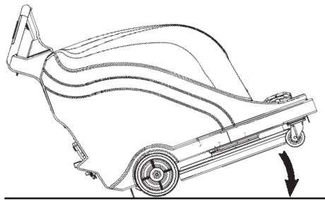
(E) PAD ASSIST MACHINE DOES NOT PULL ITSELF
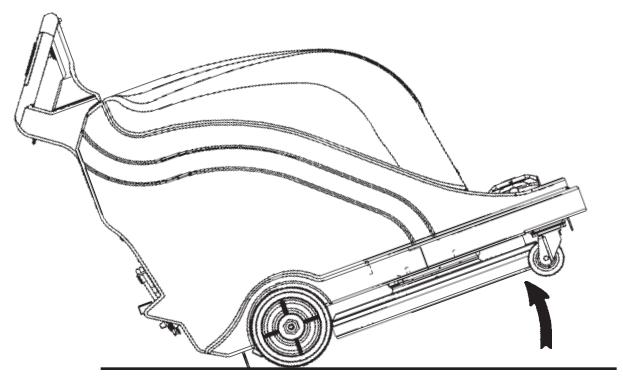
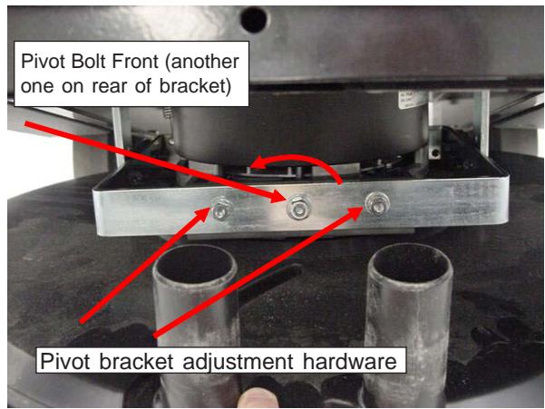
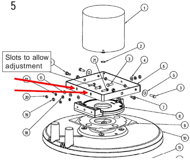
For pad assist adjustment, follow the steps below (see steps 1 - 6 in Figure E):
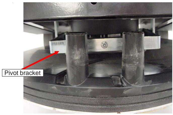
Tip burner back as shown to gain access to the pivot bracket.
2 Remove the dust bag.
3 Pull down on the dust skirt to gain access to the adjustment hardware.
4 Lossen pivot bracket adjustment hardware and pivot bolts and rotate bracket counterclockwise to increase pad assist.
5 Pivot brakethas slots to allow adjustment.
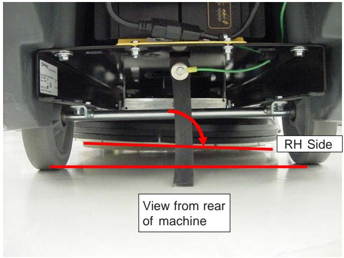
6 Adjust pivot bracket so pad is tipped down towards the RH side of the machine to increase the pad assist. Then retighten the adjustment hardware.
CAUTION!
Pad assist will vary depending on the aggressiveness of pad and the floor finish. If the deck is angled too much it could result in the pad burning the floor on the RH side.
E
1
2
3
4
5
6
INDICE
(C)- INSTALLATION DU DISQUE
This parts list is for machines after serial number EA
DESCRIPTION
Note Page 29
Assembly Drawing 30
Assembly Parts List 31
Frame Assembly Drawing 32
Frame Assembly Parts List 33
Handle Assembly Drawing 34
Handle Assembly Parts List 35
Body Assembly Drawing 36
Body Assembly Parts List 37
Head Assembly Drawing 38
Head Assembly Parts List 39
Optional Active Vac Kit Drawing 40
Optional Active Vac Kit Parts List 41
Transaxle Drawing and Parts List 42
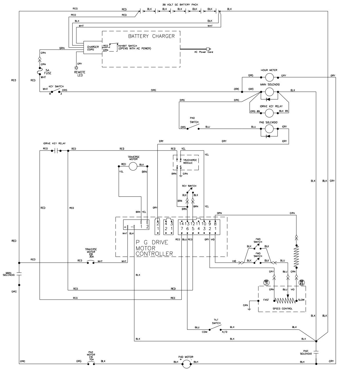
Wiring Schematic 43
WHEN ORDERING PARTS
- Use the part numbers from the "Part No." columns in this parts list.
- Specify the model and serial number of the machine.
- Use the space below to record the model and serial number for future reference.
Model Serial No.
| 08-04 | NOTE PAGE | |
| UHB 51-1500 | 29 | |
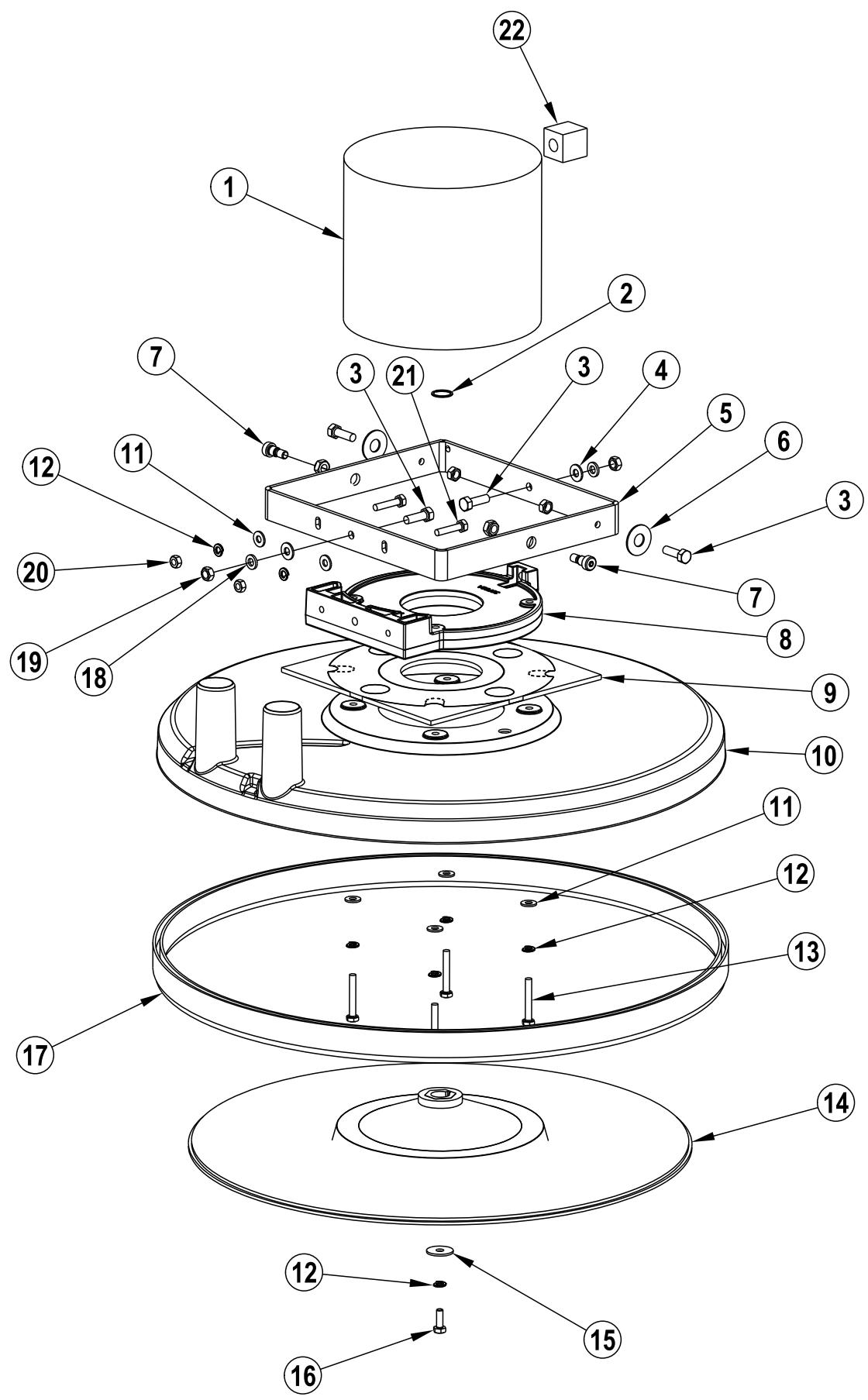
| ASSEMBLY DRAWING | 08-04 | ||
| 30 | UHB 51-1500 | ||
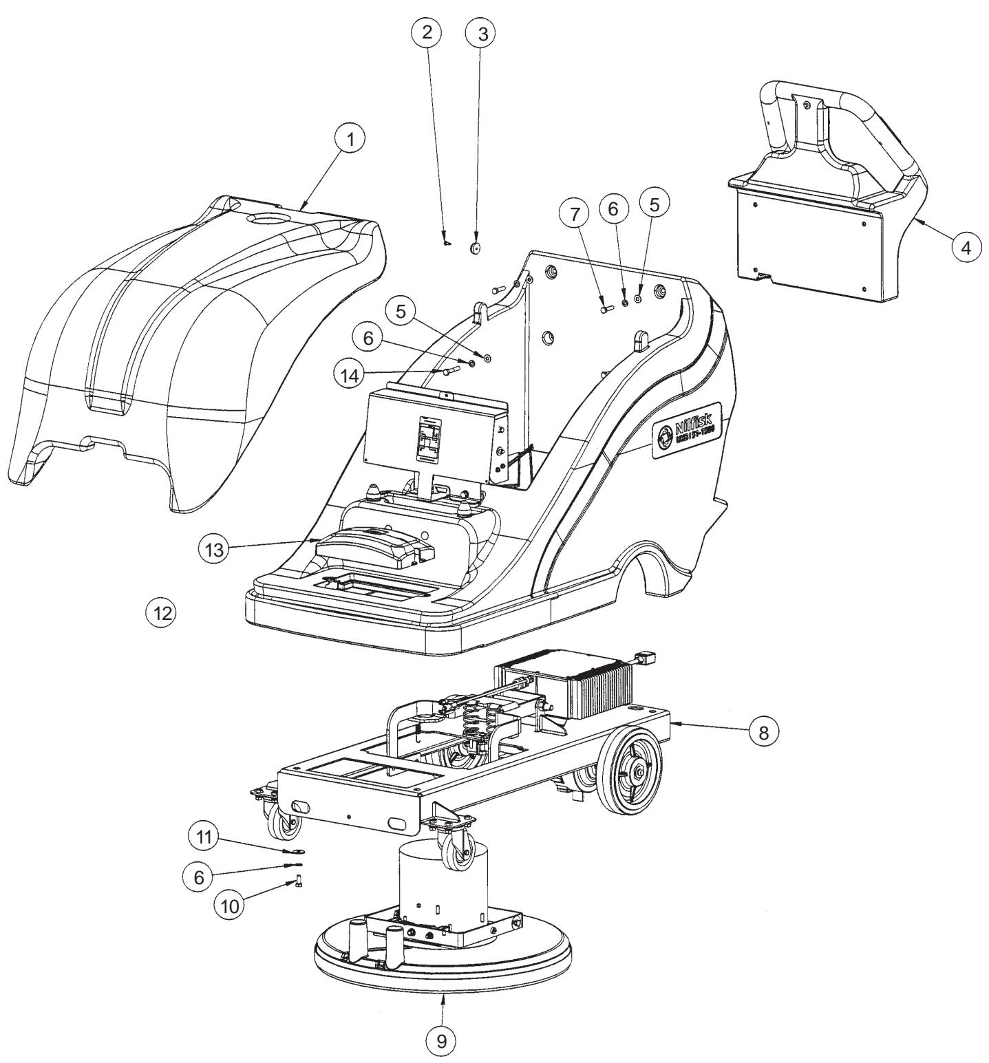
| Ref. # | Part No. | Description | Qty. |
| 1 | 30780A | Cover, Top | 1 |
| 2 | 962957 | Screw, 10-16 x 1/2 HiLo | 2 |
| 3 | 51609A | Bumper | 2 |
| 4 | Pg. 34 | Handle, Asm. Advolution 20BT | 1 |
| 5 | 980651 | Washer, 5/16 Flat | 4 |
| 6 | 980652 | Washer, 5/16 Lock | 8 |
| 7 | 85814A | Screw, 5/16-18 c 1/4 HH | 2 |
| 8 | Pg. 32 | Frame Assembly, 20" Traverse | 1 |
| 9 | Pg. 38 | Head Assembly, 20" | 1 |
| 10 | 85811A | Screw, 5/16-18 x 3/4 Hex Hd. | 4 |
| 11 | 980205 | Washer, .311 I.D. x 1.06 O.D. | 4 |
| 12 | Pg. 36 | Body Assembly | 1 |
| 13 | 30741A | Cover, Dust Bag | 1 |
| 14 | 85816A | Screw, 5/16-18 x 1.75 Hex Hd. | 2 |
| NI | 30787A | Spacer, Battery | 1 |
| NI | 41217A | Cable, Battery Series | 2 |
| NI | 41051A | Battery Cable Series Pos. | 1 |
| NI | 41050A | Battery Cable Neg. Series | 1 |
| FRAME ASSEMBLY DRAWING | 08-04 | ||
| 32 | |||
| UHB 51-1500 | |||
| Ref. # | Part No. | Description | Qty. |
| 1 | 80375A | Screw, 3/8-16 x 1 3/4 Hex Hd | 1 |
| 2 | 920148 | Nut, 3/8-16 Hex Jam | 1 |
| 3 | 61918A | Base, Two Springs | 1 |
| 4 | 980205 | Washer, .31 I.D. x 1.06 O.D. | 6 |
| 5 | 980657 | Washer, Lock 1/4 | 4 |
| 6 | 80018A | Screw, Shoulder 1/4" dia. | 1 |
| 7 | 962989 | Screw, 1/4-20 x 1 1/2 P.H. | 2 |
| 8 | 51143A | Spring, 5.75 Compression | 2 |
| 9 | 54698A | Spring, Extension .420 x 2.39 Zinc | 1 |
| 10 | 80376A | Screw, 1/2-13 x 7 H.H.C.S. | 1 |
| 11 | 54453A | Bushing, 3/8 x 1/2 Nominal | 2 |
| 12 | 61903A | Arm, Head Lift (Flat) | 1 |
| 13 | 980648 | Washer, 17/32 x 1/16 Plain | 2 |
| 14 | 920365 | Nut, 1/2-13 Nylock | 1 |
| 15 | 87060A | Insulating Bushing | 1 |
| 16 | 980646 | Waher, 1/4" Flat | 3 |
| 17 | 41036A | Charger, Battery 36VDC/25A | 1 |
| 18 | 85806A | Screw, 1/4-20 x 3/4 Hex SZ | 2 |
| 19 | 54768A | Clamp, P 5/16 Steel | 1 |
| 20 | 980651 | Washer, 5/16" Flat | 8 |
| 21 | 920208 | Nut, 1/4-20 Hex | 2 |
| 22 | 980614 | Washer, 1/4" Starlock External | 3 |
| 23 | 85700A | Screw, 1/4-20 x 1 H.H. C.S. | 1 |
| 24 | 69639A | Strap, Static | 1 |
| 25 | 962244 | Screw, 3/8-16 x .75 Hex | 4 |
| 26 | 81104A | Nut, 1/4" Nylock | 1 |
| 27 | 41043A | Transaxle | 1 |
| 28 | 915044 | Key, 3/16" Sq. | 1 |
| 29 | 962620 | Screw, 5/16-24 x 3/4" Hex Hd. | 2 |
| 30 | 54692A | Wheel, 8" | 2 |
| 31 | 62435A | Clamp, Transaxle | 2 |
| 32 | 87616A | Washer, Flat 1 x .75 x .06 Nylon | 2 |
| 33 | 920260 | Nut, 3/8-16 Hex | 4 |
| 34 | 170883 | Washer, Lock 3/8" | 4 |
| 35 | 980645 | Washer, 3/8" S.A.E. Flat | 4 |
| 36 | 85811A | Screw, 5/16-18 x 3/4 Hex | 8 |
| 37 | 980652 | Washer, 5/16 Lock | 10 |
| 38 | 54454A | Caster, 3 1/2 Front Swivel | 2 |
| 39 | 61904A | Mainframe, 20" (Weldment) | 1 |
| NI | 193951 | Trim, Vinyl Lock-8.50 Lg. | 2 |
| 34 | UHB 51-1500 | 08-04 | ||
| HANDLE ASSEMBLY DRAWING | ||||
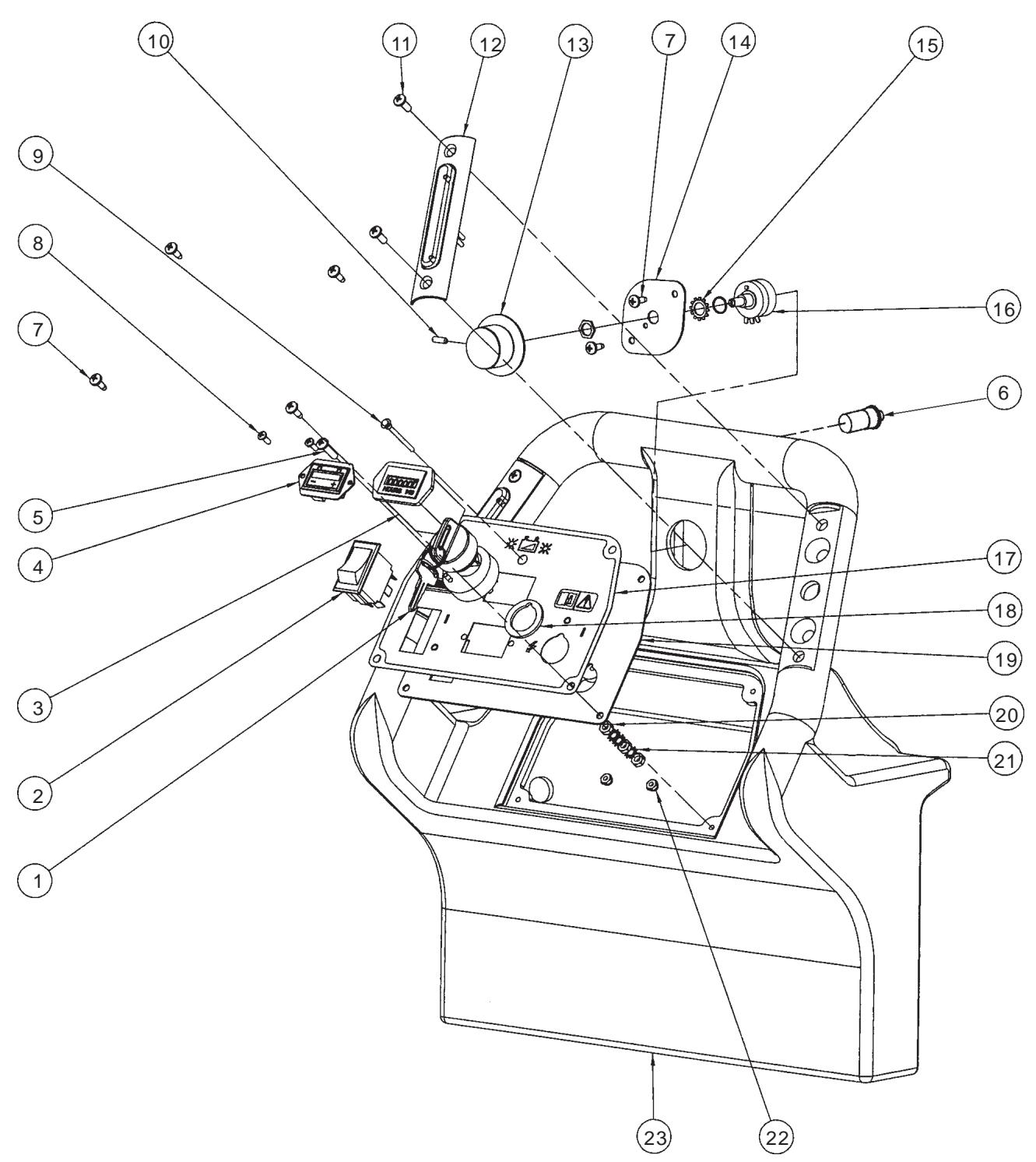
| Ref. # | Part No. | Description | Qty. |
| 1 | 40786A | Switch, Key | 1 |
| 2 | 47381B | Switch, Rocker | 1 |
| 3 | 912226 | Meter, Hour 12V DC | 1 |
| 4 | 41008A | Display, Tru-Charge | 1 |
| 5 | 85383A | Screw, 10-32 x 3/4 P.H. | 1 |
| 6 | 52556A | Switch, Push Button | 1 |
| 7 | 962957 | Screw, 10-16 x 1/2 Self Tap | 6 |
| 8 | 85313C | Screw, PHMS 6-32 x 3/8 | 2 |
| 9 | 41036A | LED, Battery Charger | 1 |
| 10 | 962262 | Screw, Set 8-32 x 1/2" | 1 |
| 11 | 80104A | Screw, 10-32 x 1/2 S.S. | 4 |
| 12 | 11178A | Switch, Assembly Handle | 2 |
| 13 | 50962A | Knob, Speed Control | 1 |
| 14 | 61922A | Retainer, 5K Potentiometer | 1 |
| 15 | 980666 | Washer, 3/8 Starlock External | 1 |
| 16 | 40750A | Harness, Potentiometer Asm. | 1 |
| 17 | 71424A | Label, Control Panel | 1 |
| 18 | 40786S | Spacer, Key Switch | 1 |
| 19 | 61906A | Panel, Control | 1 |
| 20 | 920224 | Nut, 10-32 Hex | 3 |
| 21 | 980603 | Washer, #10 Lock Ext. Tooth | 4 |
| 22 | 920056 | Nut, 6-32 E.S.N.A. Nylock | 2 |
| 23 | 30684A | Handle | 1 |
| BODY ASSEMBLY DRAWING | 08-04 | ||
| 36 | |||
| UHB 51-1500 | |||
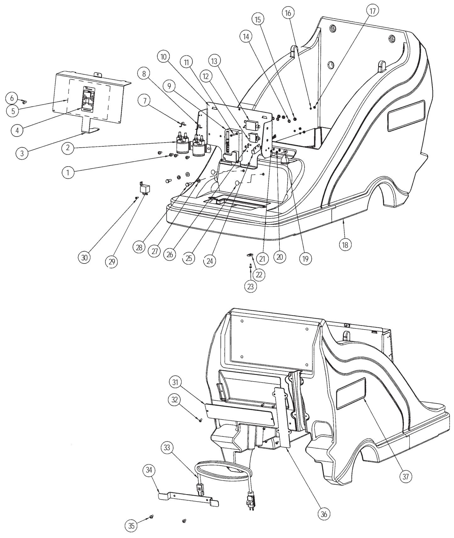
| Ref. # | Part No. | Description | Qty. |
| 1 | 962823 | Screw, 1/4-20X 1/2 P.H. | 4 |
| 2 | 41801A | Contactor, Main 36V | 2 |
| 3 | 61909A | Cover, Front Electric Plate | 1 |
| 4 | 79985A | Label, Battery Conn. | 1 |
| 5 | 79984A | Label, Connection Dia. | 1 |
| 6 | 962822 | Screw, 1/4-20 x 5/8 BT ST Scl | 1 |
| 7 | 42401A | Diode, Asm. Contactor | 1 |
| 8 | 41022A | Diode, Avalanche Asm. | 1 |
| 9 | 41042A | Controller, i-Drive 36V Traverse | 1 |
| 10 | 61905A | Plate, ElectricalWeldment | 1 |
| 11 | 80380A | Screw, 8-32 x 1 1/4" P.H. | 2 |
| 12 | 41448B | Breaker, 30A Circuit | 1 |
| 13 | 41402C | Breaker, 70A Circuit Cntrl/Act | 1 |
| 14 | 980614 | Washer, 1/4" Starlock Ext. | 4 |
| 15 | 920208 | Nut, 1/4-20 Hex | 4 |
| 16 | 87200A | Washer, Lock #8 | 4 |
| 17 | 920108 | Nut, 8-32 | 4 |
| 18 | 30778A | Cover, Lower | 1 |
| 19 | 980651 | Washer, 5/16 Flat | 2 |
| 20 | 920224 | Nut, 10-32 Hex | 2 |
| 21 | 980603 | Washer, #10 Lock Ext. Tooth | 2 |
| 22 | 52548A | Tab, 1/4" Screw | 3 |
| 23 | 962957 | Screw, 10-16 x 1/2 Self Tap | 3 |
| 24 | 41039A | Switch, Tilt | 1 |
| 25 | 54770A | Fastener, Ratchet | 2 |
| 26 | 962350 | Screw, 10-32 x .500 | 2 |
| 27 | 980652 | Washer, 5/16 Lock | 2 |
| 28 | 85811A | Screw, 5/16-18 x 3/4" Hex Hd. | 2 |
| 29 | 41007A | Relay, Traverse Power | 1 |
| 30 | 962027 | Screw, 8-32 x 1/2 P.H. | 2 |
| 31 | 38740A | Strap, Retention (Dust Bags) | 1 |
| 32 | 84237A | Screw, 10-32 x .50 P.H. | 6 |
| 33 | 40770A | Cord, Charger Schuko | 1 |
| 34 | 61598A | Bracket, CordWrap | 1 |
| 35 | 85395A | Screw, 1/4-20 x 1/2" P.H. | 2 |
| 36 | 38739A | Cover, Harness | 1 |
| 37 | 71435A | Label, UHB 51-1500 | 2 |
| NI | 41041A | Harness, Power 20" Traverse | 1 |
| NI | 41038A | Harness, Logic 20" Traverse | 1 |
| NI | 193951 | Trim, 3" Flexible | 1 |
| HEAD ASSEMBLY DRAWING | 08-04 | ||
| 38 | 10-05 | ||
| Ref. # | Part No. | Description | Qty. |
| 1 | 41066A | Motor | 1 |
| 56407500 | Carbon Brush/Spring Set | 1 | |
| 2 | 80378A | Ring, Retaining External 0.750" | 1 |
| 3 | 85813A | Screw, 5/16-18 x 1.00 Hex Hd. | 4 |
| 4 | 980651 | Washer, 5/16 Flat | 2 |
| 5 | 61916A | Frame, Motor (Weldment) | 1 |
| 6 | 87607A | Washer, Nylon 1.25 x .52 x .06 Flat | 2 |
| 7 | 80040A | Screw, Shoulder 3/8x 3/8 | 2 |
| 8 | 30783A | Mount, Motor | 1 |
| 9 | 54435A | Gasket, 2 Piece | 1 |
| 10 | 30739A | Shroud, Dust | 1 |
| 11 | 980646 | Washer, 1/4" Flat | 6 |
| 12 | 980657 | Washer, Lock 1/4 | 7 |
| 13 | 85702A | Screw, 1/4-20 x 1-3/4 Hex Cap | 4 |
| 14# | 56925A | Pad Driver TSBUS2009-1034 | 1 |
| [] | 57369A | Center Lock | 1 |
| 15 | 980205 | Washer, .31 I.D. x 1.06 O.D. | 1 |
| 16 | 85806A | Screw, 1/4-20 x 3/4 Hex Sz. | 1 |
| 17 | 56393565 | SkirtAssembly | 1 |
| 18 | 980652 | Washer, 5/16 Lock | 2 |
| 19 | 170854 | Nut, 5/18 Hex | 4 |
| 20 | 920208 | Nut, 1/4-20 Hex | 2 |
| 21 | 962481 | Screw, 1/4-20 x 1 1/4 H.H.C.S. | 2 |
| 22# | 40849A | Suppressor EMI Split | 1 |
[ \left[ \right] = \text{Not Shown} ]
# = Revised or new since last update
| ACTIVE VAC KIT 11223A DRAWING | 08-04 | ||
| 40 | UHB 51-1500 | ||
NOTE: This is offered as an optional kit only.
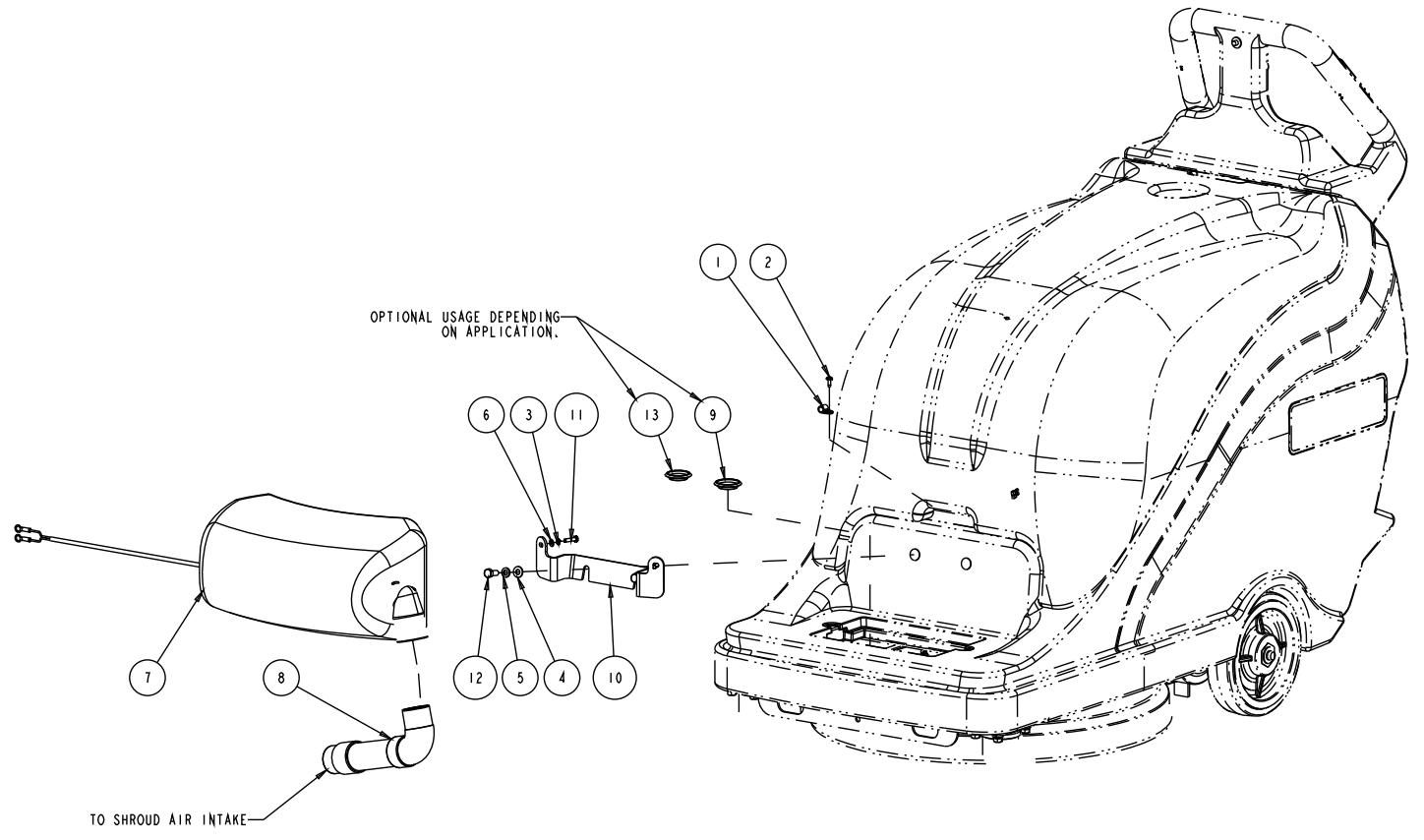
| 08-04 | ACTIVE VAC KIT 11223A PARTS LIST | ||
| 09-12 | UHB 51-1500 | 41 | |
ITEM PART NO. QTY DESCRIPTION
[] 71473A 1 Instruction Sheet
1 872102 Clamp, Wire .312 ID
2 962957 1 Screw, 10-16 x 1/2 Self Tap
3 980650 2 Washer,#10Lock
4 980651 2 Washer, 5/16 Flat
5 980652 2 Washer, 5/16 Lock
6 980982 2 Washer,#10 SAE Flat
7 11224A 1 Vacuum, Active
8 38044A 1 Hose, Vacuum
9 38045A 1 Cap, Shroud
10 61921A 1 Bracket, Acuvac
11 80205A 2 Screw, M5 x 0.8 x 20MM Pan Head
12 85811A 2 Screw, 5/16-18 x 3/4 Hex Hd
13 56380133 1 Plug-Hole 1-5/16
Accessories
[ ] 1406554010 A/R Dust Bag-58 Gallon-Pack of 5
[ ] 1406794010 A/R Round Motor Protection Filter-Pack of 1
[] 1406597500 A/R Exhaust Filter-Pack of 3
[ ] 1406908000 A/R Cloth Dust Bag-Reusable/Shake out
[] = Not Shown
| TRANSAXLE DRAWING & PARTS LIST | 08-04 | ||
| 42 | |||
| UHB 51-1500 | |||
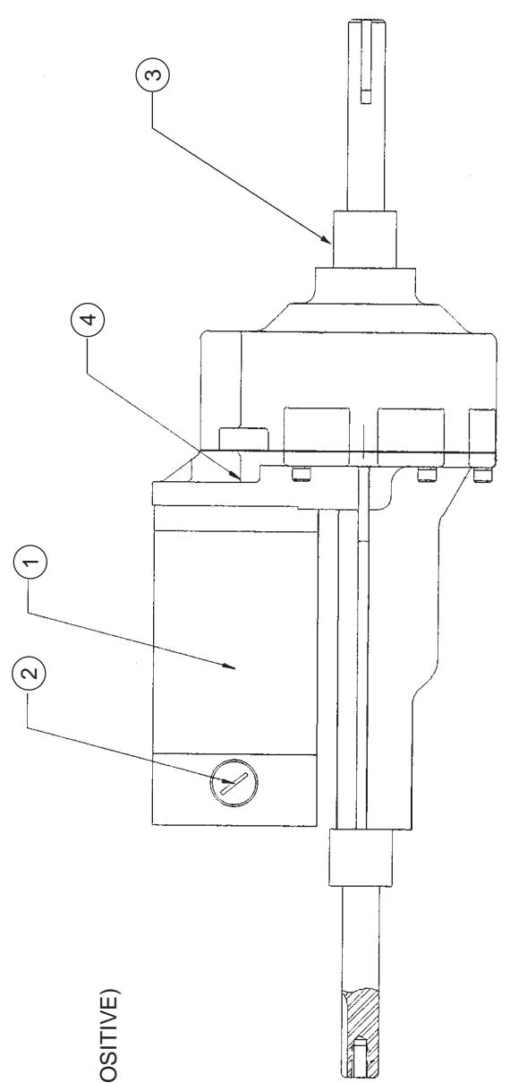
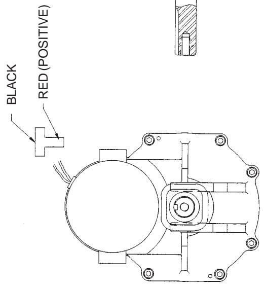
MOTOR SPECIFICATIONS:
Voltage: 36 VDC
Free Speed: ~ 130 RPM
Torque: 140 in-lbs @ 110 RPM (Ref. Only)
PARTS LIST
| Ref. # | Part No. | Description | Qty. |
| 1 | 52804A | Motor, Transaxle | 1 |
| 2 | 52803A | Brush, Asm. | 2 |
| 3 | 51056A | Elastomeric Sleeve | 2 |
| 4 | 52801A | Coupler, Transaxle | 1 |
| PENNY & GILES CONTROL CONNECTIONS |
| 1 THROTTLE WIPER 2 THROTTLE HIGH 3 AUX 2 OUT 4 SLOW/FAST SWT 5 KEY SW 6 INHIBIT 1 PROGRAM TO INHIBIT TRAV AND PAD WHEN TILT SWITCH IS CLOSED 7 FUSED 36V OUT 8 THROTTLE LOW 9 BELLY SWT 10 STATUS IND. 11 AUX 3 OUT 12 REV SWT 13 O VOLT 14 INHIBIT 2 CHARGER |
| STATIC | GROUND | CIRCUIT |
| ELETRICAL PANEL | SPEED POT | CTBL PANEL |
Overenstemmelseserklaering
Declaration of conformity
GB The undersigned certify that the above mentioned model is produced in accordance with the following directives and standards.
DK Undertegnede attesterer herved, at ovennnvnte model er produceret i overensstemmelse med ffolgende direktiver og standarder.
N Undertegnede attesterer att ovennevnte modell ar produsert I overensstemmelse med folgende direktiv og standarder.
EC Machinery Directive 98/37/EC
EC Low Voltage Directive 73/23/EEC, 93/68/EEC, 06/95/EEC
EC EMC Directive 89/336/EEC
EC Outdoor Noise Directive 2000/14/EC
EN 12100-1, EN 12100-2, EN 294, EN 349
EN 60335-1, EN 60335-2-72
EN 61000, EN 50366

1.22.2010
Year of Affixing the CE marking 2010
Don Legatt, Engineering Director
Nilfisk-Advance, Inc.
14600 21st Avenue North
Plymouth, MN 55447 USA
Nilfisk-Advance A/S
Sognevej 25
DK-2605 Brøndby, Denmark
Nilfisk-Advance A/S