
BRX 700 EDS - Pressure washer NILFISK - Free user manual and instructions
Find the device manual for free BRX 700 EDS NILFISK in PDF.
| Product type | High-pressure washer / Commercial carpet extractor |
| Brand | Nilfisk |
| Model | BRX 700 EDS |
| Supply voltage | 36 V (battery) |
| Rated current | 65 A |
| Battery capacity | 238 Ah |
| Protection rating | IPX3 |
| Weight | 712 kg |
| Sound power level | 73 dB(A) |
| Solution tank capacity | 151 L |
| Battery type | Lead-acid (with electrolyte) |
| Detergent system | EDS (electronic injection) |
| Cleaning modes | Maintenance, Restoration |
| Maximum forward speed | 5 km/h |
| Maximum slope in cleaning | 10 % (6°) |
| Maximum slope in transport | 14 % (8°) |
| Vibrations at the steering wheel | < 2.5 m/s² |
| Vibrations at the seat | < 0.5 m/s² |
| Use | Commercial |
| Maintenance | Daily, weekly, monthly, yearly (see manual) |
| Safety | Emergency stop, battery disconnect, stop float |
| Spare parts | Available from authorized Nilfisk centers |
Frequently Asked Questions - BRX 700 EDS NILFISK
User questions about BRX 700 EDS NILFISK
0 question about this device. Answer the ones you know or ask your own.
Ask a new question about this device
Download the instructions for your Pressure washer in PDF format for free! Find your manual BRX 700 EDS - NILFISK and take your electronic device back in hand. On this page are published all the documents necessary for the use of your device. BRX 700 EDS by NILFISK.
USER MANUAL BRX 700 EDS NILFISK
Prepare the Machine for Use
Description of the Battery Condition Indicators A-6
Install the Batteries. A-6
Filling the Solution Tank. A-7
Pre-Spraying the Carpet. A-7
Plan for Cleaning. A-7
Detergent (EDS) System Preparation & Use. A-8-9
Operating the Machine . A-10
Using Attachments. A-10
After Use. A-11
Maintenance Schedule. A-11
Vacuum Shoe Maintenance. A-11
Spray Nozzle Maintenance. A-11
Lubricating the Machine A-11
Cleaning the Vacuum Motor Filters A-11
Power Brush Maintenance A-11
Removing the Brushes . A-12
Removing the Vacuum Shoes. A-12
Charging the Batteries. A-12
Check the Battery Electrolyte Level. A-12
Troubleshooting. A-13
Technical Specifications . A-14
INTRODUCTION
This manual will help you get the most from your Nilfisk Rider Extractor. Read it thoroughly before operating the machine.
Note: Bold numbers in parentheses indicate an item illustrated on pages A-4 - A-5.
This product is intended for commercial use only.
PARTS AND SERVICE
Repairs, when required, should be performed by your Authorized Nilfisk Service Center, who employs factory trained service personnel, and maintains an inventory of Nilfisk original replacement parts and accessories.
Call the NILFISK DEALER named below for repair parts or service. Please specify the Model and Serial Number when discussing your machine.
(Dealer, affix service sticker here.)
NAME PLATE
The Model Number and Serial Number of your machine are shown on the Nameplate on the machine. This information is needed when ordering repair parts for the machine. Use the space below to note the Model Number and Serial Number of your machine for future reference.
MODEL NUMBER
SERIAL NUMBER
UNCRATE THE MACHINE
When the machine is delivered, carefully inspect the shipping packaging and the machine for damage. If damage is evident, save the shipping carton (if applicable) so that it can be inspected. Contact the Nilfisk Customer Service Department immediately to file a freight damage claim. Refer to the unpacking instruction sheet included with the machine to remove the machine from the pallet.
CAUTIONS AND WARNING
SYMBOLS
Nilfisk uses the symbols below to signal potentially dangerous conditions. Always read this information carefully and take the necessary steps to protect personnel and property.
DANGER!
Is used to warn of immediate hazards that will cause severe personal injury or death.
WARNING!
Is used to call attention to a situation that could cause severe personal injury.
CAUTION!
Is used to call attention to a situation that could cause minor personal injury or damage to the machine or other property.

Read all instructions before using.
GENERAL SAFETY INSTRUCTIONS
Specific Cautions andWarnings are included to warn you of potential danger of machine damage or bodily harm.
WARNING!
This machine shall be used only by properly trained and authorized persons.
While on ramps or inclines, avoid sudden stops when loaded. Avoid abrupt sharp turns. Use low speed down hills. Clean only while ascending (driving up) the ramp.
- Keep sparks, flame and smoking materials away from batteries. Explosive gases are vented during normal operation.
- Charging the batteries produces highly explosive hydrogen gas. Charge batteries only in well-ventilated areas, away from open flame. Do not smoke while charging the batteries.
- Remove all jewelry when working near electrical components.
- Turn the key switch off (O) and disconnect the batteries before servicing electrical components.
- Never work under a machine without safety blocks or stands to support the machine.
- Do not dispense flammable cleaning agents, operate the machine on or near these agents, or operate in areas where flammable liquids exist.
- Do not clean this machine with a pressure washer.
CAUTION!
This machine is not approved for use on public paths or roads.
This machine is not suitable for picking up hazardous dust.
- When operating this machine, ensure that third parties, particularly children, are not endangered.
Before performing any service function, carefully read all instructions pertaining to that function.
- Do not leave the machine unattended without first turning the key switch off (O), removing the key and applying the parking brake.
- Turn the key switch off (O) before changing the brushes, and before opening any access panels.
Take precautions to prevent hair, jewelry, or loose clothing from becoming caught in moving parts.
Use caution when moving this machine in below freezing temperature conditions. Any water in the solution, recovery or detergent tanks or in the hose lines could freeze, causing damage to valves and fittings. Flush with windshield washer fluid.
- The batteries must be removed from the machine before the machine is scrapped. The disposal of the batteries should be safely done in accordance with your local environmental regulations.
SAVE THESE INSTRUCTIONS
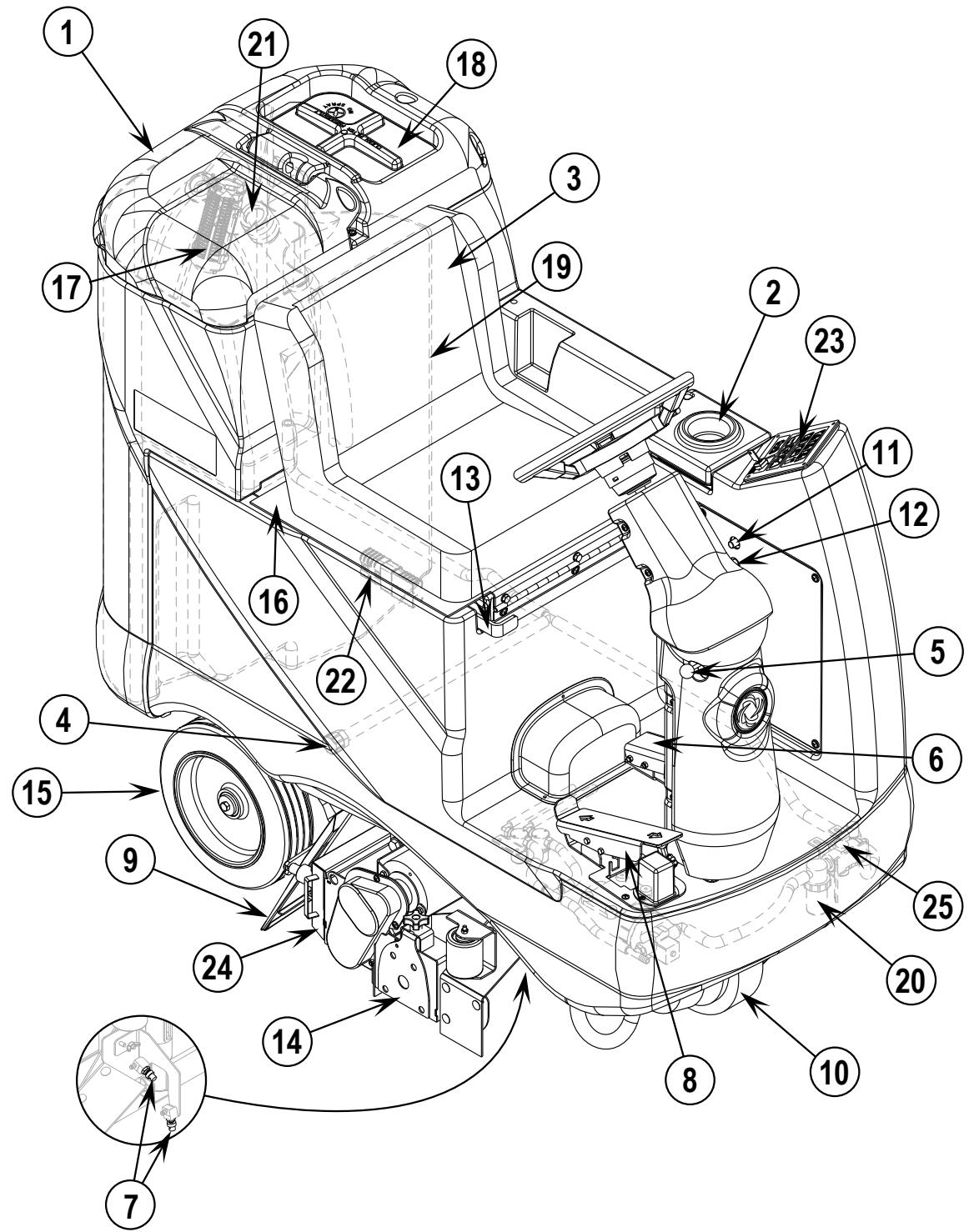
KNOW YOUR MACHINE
1 Recovery Tank Cover
2 Solution Tank Fill Cover
3 Operator's Seat
4 Solution Tank Drain Hose
5 Steering Wheel Tilt Adjust Knob
6 Brake Pedal / Parking Brake
7 Solution Spray Jets
8 Drive Pedal, Directional/Speed
9 Vacuum Shoes
10 Drive and Steer Wheel
11 Wheel Drive Circuit Breaker
12 Control Circuit Circuit Breaker
13 Emergency Stop Switch / Battery Disconnect
14 Brush Deck
15 Rear Wheel
16 Battery Compartment (under seat)
17 Recovery Bladder Shutoff Float
18 Vacuum Motor Filter Housing
19 Recovery Bladder
20 Solution Filter
21 Recovery Bladder Drain Hose (rear of machine)
22 Machine Battery Connector
23 Control Panel
24 Debris Hopper
25 Solution Control Valve
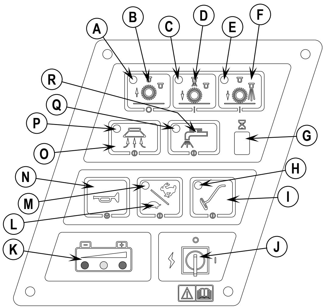
CONTROL PANEL
A Scrub OFF Indicator
B Scrub OFF Switch
C Maintenance Mode Indicator
D Maintenance Mode Switch
E Restoration Mode Indicator
F Restoration Mode Switch
G Hourmeter Display
H Accessory Vacuum Indicator
I Accessory Vacuum ON / OFF Switch
J Key Switch / Main Power
K Battery Condition Indicator
L Speed Select Switch (extract / transport)
M Speed Select Indicator
N Horn Switch
O Vacuum Switch
P Vacuum System Indicator
Q Solution System Indicator
R Solution Switch
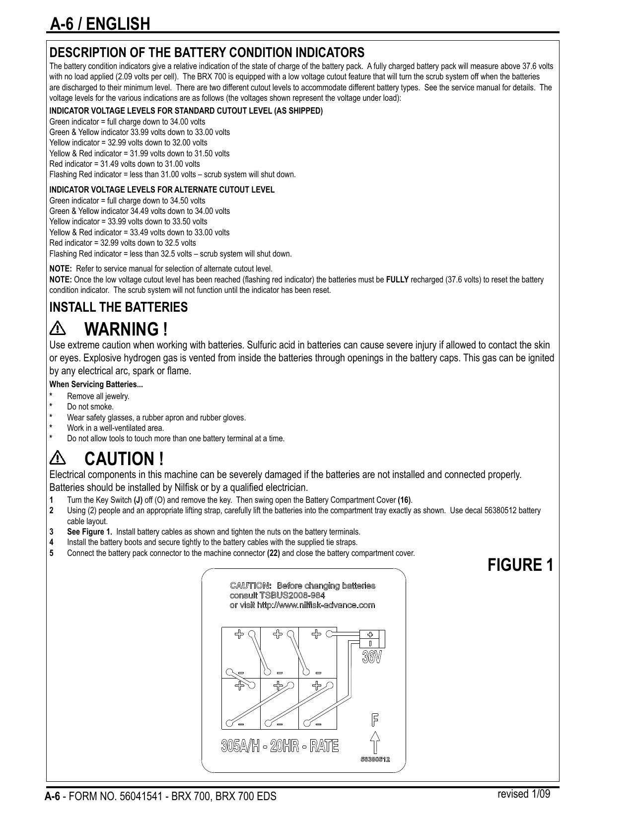
DESCRIPTION OF THE BATTERY CONDITION INDICATORS
The battery condition indicators give a relative indication of the state of charge of the battery pack. A fully charged battery pack will measure above 37.6 volts with no load applied (2.09 volts per cell). The BRX 700 is equipped with a low voltage cutout feature that will turn the scrub system off when the batteries are discharged to their minimum level. There are two different cutout levels to accommodate different battery types. See the service manual for details. The voltage levels for the various indications are as follows (the voltages shown represent the voltage under load):
INDICATOR VOLTAGE LEVELS FOR STANDARD CUTOUT LEVEL (AS SHIPPED)
Green indicator = full charge down to 34.00 volts
Green & Yellow indicator 33.99 volts down to 33.00 volts
Yellow indicator = 32.99 volts down to 32.00 volts
Yellow & Red indicator = 31.99 volts down to 31.50 volts
Red indicator = 31.49 volts down to 31.00 volts
Flashing Red indicator = less than 31.00 volts - scrub system will shut down.
INDICATOR VOLTAGE LEVELS FOR ALTERNATE CUTOUT LEVEL
Green indicator = full charge down to 34.50 volts
Green & Yellow indicator 34.49 volts down to 34.00 volts
Yellow indicator = 33.99 volts down to 33.50 volts
Yellow & Red indicator = 33.49 volts down to 33.00 volts
Red indicator = 32.99 volts down to 32.5 volts
Flashing Red indicator = less than 32.5 volts - scrub system will shut down.
NOTE: Refer to service manual for selection of alternate cutout level.
NOTE: Once the low voltage cutout level has been reached (flashing red indicator) the batteries must be FULLY recharged (37.6 volts) to reset the battery condition indicator. The scrub system will not function until the indicator has been reset.
INSTALL THE BATTERIES
WARNING!
Use extreme caution when working with batteries. Sulfuric acid in batteries can cause severe injury if allowed to contact the skin or eyes. Explosive hydrogen gas is vented from inside the batteries through openings in the battery caps. This gas can be ignited by any electrical arc, spark or flame.
When Servicing Batteries...
- Remove all jewelry.
- Do not smoke.
- Wear safety glasses, a rubber apron and rubber gloves.
- Work in a well-ventilated area.
- Do not allow tools to touch more than one battery terminal at a time.
CAUTION!
Electrical components in this machine can be severely damaged if the batteries are not installed and connected properly.
Batteries should be installed by Nilfisk or by a qualified electrician.
1 Turn the Key Switch (J) off (O) and remove the key. Then swing open the Battery Compartment Cover (16).
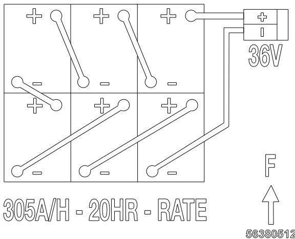
2 Using (2) people and an appropriate lifting strap, carefully lift the batteries into the compartment tray exactly as shown. Use decal 56380512 battery cable layout.
3 See Figure 1. Install battery cables as shown and tighten the nuts on the battery terminals.
4 Install the battery boots and secure tightly to the battery cables with the supplied tie straps.
5 Connect the battery pack connector to the machine connector (22) and close the battery compartment cover.
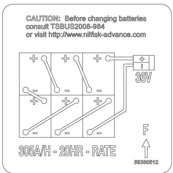
FIGURE 1
FILLING THE SOLUTION TANK
1 Open the Solution Tank Fill Cover (2).
2 Read the dilution instructions on the chemical container. Then figure the proper amount of chemical to mix with 40 gallons (151 liters) of water.
Pour the proper amount of chemical into the solution tank and fill the tank with warm water to 7.62cm (3 inches) from the top of the tank opening.
4 Close the Solution Tank Fill Cover (2).
NOTE: If your machine was factory equipped with a chemical system you DO NOT mix chemical in the solution tank.
CAUTION!
Use low-sudsing, liquid detergents designed for carpet extraction. Water temperature should not exceed 130 degrees Fahrenheit (54.4 degrees Celsius).
BEFORE USING THE BRX 700
Thorough vacuuming of the carpet to be cleaned is not necessary before using the BRX 700 automatic extractors, due to the on-board sweeping broom and debris hopper.
PRE-SPRAYING THE CARPET
Pre-spray spots and heavy traffic areas before extracting. Use a hand-held bottle sprayer or a pressurized "Hudson" type sprayer. Mix the pre-spray according to the chemical manufacturer's directions.
PLAN FOR CLEANING
Before you begin extracting, look at the area to be cleaned and plan your work. Divide the space into sections. Overlap each pass 2 inches (5 cm).
DETERGENT (EDS) SYSTEM PREPARATION AND USE
COMMON INSTRUCTIONS:
The system should be purged of previous detergent when switching to a different detergent. SERVICE NOTE: Move machine over floor drain before purging because a small amount of detergent will be dispensed in the process.
To Purge When Changing Chemicals:
1 Disconnect and remove the detergent cartridge.
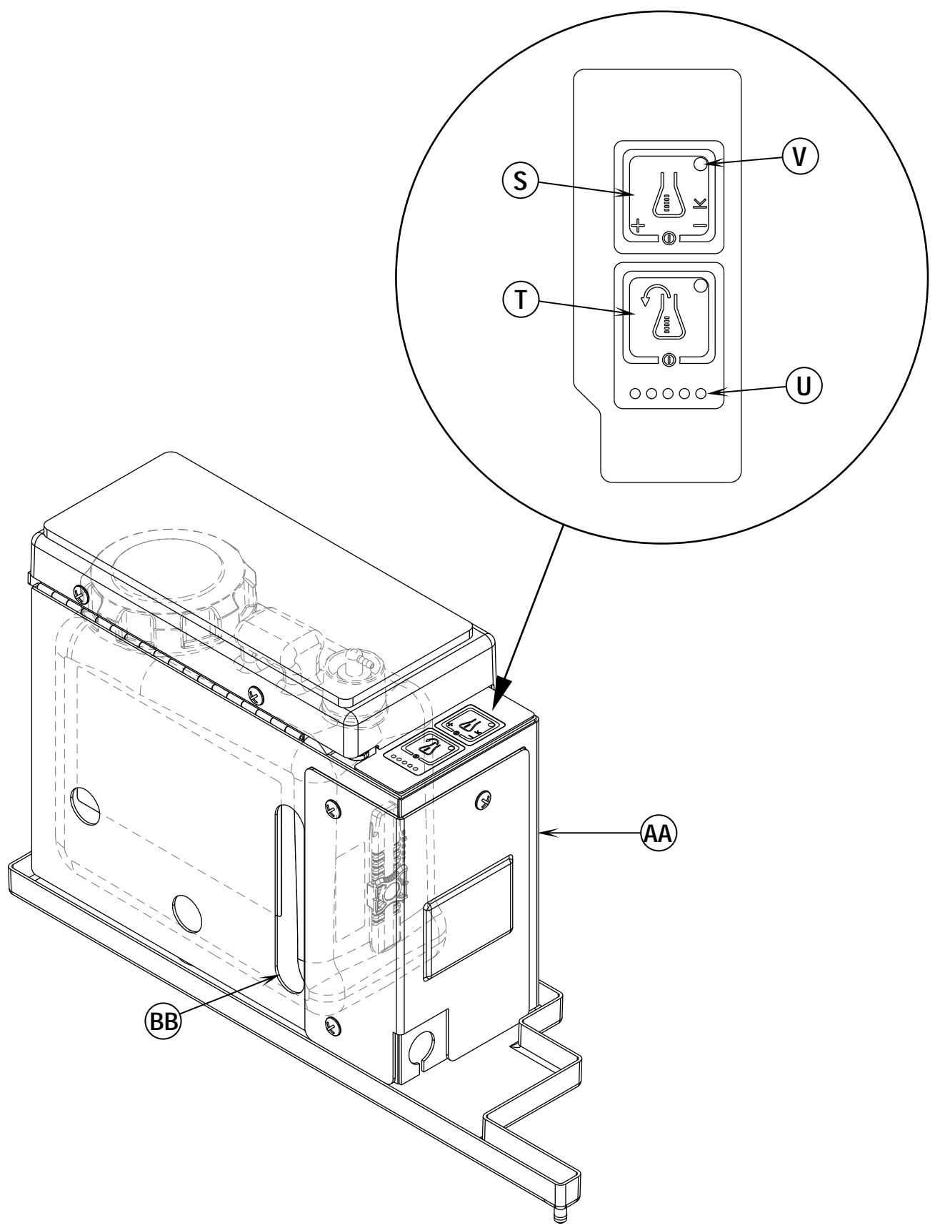
2 Turn the Key Switch (J) ON. Press and hold the Purge Switch (T) down for at least 3 seconds, then press and hold the Solution Switch (R) (on the main machine's control panel) for the duration of the purge cycle. Holding the solution switch is necessary to open the solution valve and prevent the purged detergent from flowing back into the solution tank. NOTE: Once activated the Purge Indicator (U) will begin to scroll a flashing light from left to right and will automatically shut off after 10 seconds. Normally one purge cycle is adequate to purge the system.
To Purge Weekly:
1 Disconnect and remove the detergent cartridge. Install and connect a Cartridge filled with clean water.
2 Turn the Key Switch (J) ON. Press and hold the Purge Switch (T) down for at least 3 seconds, then press and hold the Solution Switch (R) (on the main machine's control panel) for the duration of the purge cycle. Holding the solution switch is necessary to open the solution valve and prevent the purged detergent from flowing back into the solution tank. NOTE: Once activated the Purge Indicator (U) will begin to scroll a flashing light from left to right and will automatically shut off after 10 seconds. Normally one purge cycle is adequate to purge the system.
The Detergent Box (AA) has a Detergent Level Viewing Slot (BB) for keeping track of how much detergent is remaining in the cartridge. When the detergent level is nearing the bottom of this slot it is time to refill or replace the cartridge.
General Use:
The detergent injection system is activated when the Key Switch (J) is turned on but no detergent is dispensed until the scrub system is activated and the Drive Pedal (B) pushed forward. The solution flow rate is determined by the use of "Maintenance" or "Restoration" mode. The solution flow rate can be changed by pressing the Maintenance Extract Mode Switch (D) for reduced flow or the Restoration Extract Mode Switch (F) for increased flow. The detergent flow rate increases or decreases with the solution flow rate but the detergent ratio remains the same. During scrubbing, the detergent system can be turned off at any time by pressing the Detergent ON/OFF Switch (S) to allow scrubbing with water only. SERVICE NOTE: Follow the "To Purge Weekly" instructions above if the machine is going to be stored for an extended period of time or if you plan to discontinue use of the detergent injection system.
DISPOSABLE CARTRIDGE SPECIFIC INSTRUCTIONS:
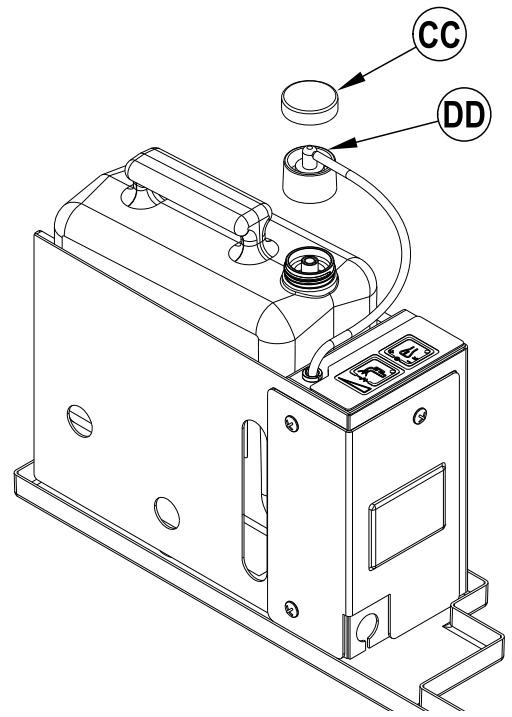
Remove the Cap (CC) and place the cartridge in the detergent box. Install the Dry Break Cap (DD) as shown.
NON- DISPOSABLE CARTRIDGE SPECIFIC INSTRUCTIONS:
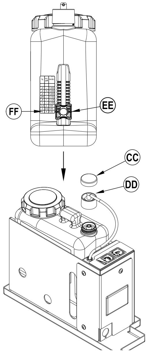
Fill the detergent cartridge with a maximum of 1.25 gallons (4.73 Liters) of detergent. SERVICE NOTE: Remove the detergent cartridge from the detergent box prior to filling to avoid spilling detergent on the machine.
It is recommended that a separate cartridge be used for each detergent you plan to use. The detergent cartridges have a white decal on them so you can write the detergent name on each cartridge to avoid mixing them up. The detergent cartridge has a Magnetic Slider (EE) on one end that needs to be set to the proper dilution ratio according to the dilution instructions on the manufacturer's bottle. Slide the Magnet Slider (EE) to the appropriate location on Detergent Dilution Ratio Decal (FF). When installing a new cartridge, remove the Cap (CC) and place the cartridge in the detergent box. Install the Dry Break Cap (DD) as shown.
DETERGENT (EDS) SYSTEM PREPARATION AND USE
Be sure you understand the operator controls and their functions.
While on ramps or inclines, avoid sudden stops when loaded. Avoid abrupt sharp turns. Use low speed down hills. Clean only while ascending (driving up) the ramp.
To Extract...
Follow the instructions in preparing the machine for use section of this manual.
1 While seated on the machine, adjust the steering wheel to a comfortable operating position using the adjustment knob (5).
2 Turn the Master Key Switch (J) ON (I). This will display the control panel indicator lights, reference the Battery Condition Indicator (K) and Hour Meter (G).
3 Release the Parking Brake (6). To transport the machine to the work area, apply even pressure with your foot on the front of the Drive Pedal (8) to go forward or the rear of the pedal for reverse. Vary the pressure on the foot pedal to obtain the desired speed.
4 Press either the Maintenance Mode Switch (D) or the Restoration Mode Switch (F) to activate the scrub system. Note: refer to the "Functional Description of Control Switches" section for a more detailed explanation of these and other control panel functions.
NOTE (EDS Models): The Detergent system is activated by default when the Key Switch (J) is turned ON (I). The Detergent ON/OFF Indicator (V) is lit when the detergent system is activated. The Detergent system can be turned OFF by pressing the Detergent ON/OFF Switch (S). When the system is activated detergent flows whenever solution flows.
When either the Maintenance Mode Switch (D) or the Restoration Mode Switch (F) is selected, the brush deck and vacuum shoes are automatically lowered to the floor. The machine's scrub brush rotation and solution system flow starts when the Drive Pedal (8) is activated. NOTE: When operating the machine in reverse, solution will not be dispensed. The brush deck can be programmed to raise in reverse, have a qualified service technician refer to the service manual to perform this function.
6 Begin cleaning by driving the machine forward in a straight line at a normal walking speed and overlap each path by 2-3 inches (50-75 mm). Turn the Solution Switch (R) OFF prior to turns to ensure complete extraction of solution from carpet. Adjust when necessary the machine speed according to the condition of the carpet.
If there is little or no fluid entering the recovery bladder, the solution tank may be empty. Refill the solution tank with water and the proper ratio of cleaning chemical.
7 The recovery bladder has an automatic float shut-off to prevent solution from entering the vacuum system when the recovery bladder is full. When the float shut-off is activated, the control system will shut down the scrub, vacuum, solution and detergent (EDS models) systems. The Hourmeter Display (G) will display "FULL". To clear the display, press the Scrub OFF Switch (B), Maintenance Mode Switch (D) or the Restoration Mode Switch (F). When the float closes, the recovery bladder must be emptied. The machine will not pick up water with the float closed. NOTE: If the control repeatedly gives a full indication when the tank is not full, the automatic shut-off feature can be disabled, have a qualified service technician refer to the service manual to perform this function.
8 When the operator wants to stop cleaning or the recovery bladder is full, press the Scrub OFF Switch (B). This will automatically stop the scrub brushes and solution flow and the brush deck will raise to the up position. NOTE: The vacuum system will be turned off after a 10 second delay this is to allow any remaining water in the pick up hose to be brought into the recovery bladder.
9 Drive the machine to a designated waste water "DISPOSAL SITE" and empty the recovery bladder. To empty, pull the Drain Hose (21) from its rear storage area, then remove the plug (hold the end of the hose above the water level in the tank to avoid sudden, uncontrolled flow of waste water). Refill the solution tank and continue cleaning.
USING ATTACHMENTS
Steps to follow in fitting the machine with optional attachments for detail or upholstery cleaning.
1 Disconnect the recovery hose connection at the Y-fitting, which goes to the vacuum shoes. Connect the coupler and hose from suitable wet pick-up tools to the recovery hose.
2 Attach the solution connection to the accessory port, located at the rear of the machine on the chassis. (An optional Wand Caddy Kit is available from Nilfisk).
3 Turn the Master Key Switch (J) ON, next press the Accessory Vacuum Switch (I). The vacuum motor will run continuously until the switch is pressed again to turn it OFF. NOTE: If the control repeatedly gives a full indication when the tank is not full, the automatic shut-off feature can be disabled, have a qualified service technician perform this function.
AFTER USE
When finished cleaning, press the Scrub Off Switch (B), this will automatically raise, retract and stop all the machine systems (brush, vacuum & solution). Then drive the machine to a service area for daily maintenance and review of other needed service up-keep.
2 To empty the solution tank, remove the Solution Drain Hose (4) from its storage clamp. Direct the hose to a designated "DISPOSAL SITE" and remove the plug. Rinse the tank with clean water.
3 To empty the recovery bladder, pull the Recovery Bladder Drain Hose (21) from its storage area. Direct the hose to a designated "DISPOSAL SITE" and remove the plug (hold the end of the hose above the water level in the tank to avoid sudden, uncontrolled flow of waste water). Rinse the Waste water Bladder (19) with clean water.
4 Remove the Brushes, rinse with warm water and remove any built-up string, hair or carpet fibers.
5 Disconnect the Recovery Hose from the Recovery Tank and flush with warm water to wash any debris out of the Recovery Hose / Vacuum Shoe Assembly.
6 Remove the debris hopper and clean thoroughly. Remove from left or right side of machine by lifting hopper up and tilting it forward then pull out.
7 Check the maintenance schedule below and perform any required maintenance before storage.
MAINTENANCE SCHEDULE
| MAINTENANCE ITEM | Daily | Weekly | Monthly | Yearly |
| Charge Batteries | • | |||
| Check/Clean Tanks & Hoses | • | |||
| Check/Clean/ Power Brushes | • | |||
| Check/Clean Vacuum Shoes | • | |||
| Check/Clean Vacuum Shut-Off Float | • | |||
| Check/Clean the vacuum motor foam filter(s) | • | |||
| Empty Debris Hopper | • | |||
| Clean Spray Nozzles | • | |||
| Check Each Battery Cell(s) Water Level | • | |||
| Inspect Brush Deck Skirts | • | |||
| Inspect and clean Solution Filter | • | |||
| Check Foot/ Parking Brake for Wear & Adjustment | • | |||
| Purge the Detergent Injection System (EDS models only) | • | |||
| Lubrication - Grease Fittings | • | |||
| * Check Carbon Brushes | • |
- Have Nilfisk check the vacuum motor carbon motor brushes once a year or after 300 operating hours. The brush and drive motor carbon brushes check every 350 hours or once a year.
NOTE: Refer to the Service Manual for more detail on maintenance and service repairs.
8 Store the machine indoors in a clean dry place. Keep from freezing. Leave the tanks open to air them out.
9 Turn the Master Key Switch (J) OFF (O) and remove the key.
Check the vacuum shoes daily, they can be removed to aid in cleaning, see "Removing the Vacuum Shoes". Remove any built-up string, hair or carpet fibers.
SPRAY NOZZLE MAINTENANCE
Remove the spray nozzles once a week. Soak the nozzles overnight in a vinegar and water solution to remove chemical deposits.
LUBRICATING THE MACHINE
Once a month, pump a small amount of grease into each grease fitting on the machine until grease seeps out around the bearings.
Grease fitting locations are:
- Steering Wheel Shaft Universal joint
Once a month, apply light machine oil to lubricate the:
- Steering Chain
- General Pivot Points For the Brush Deck Linkage
CLEANING THE VACUUM MOTOR FILTERS
Clean the vacuum motor filters daily with compressed air. For extremely dirty filters, wash with warm, soapy water and rinse thoroughly with clean water. Allow the filters to dry completely before re-installing in the machine. MAINTENANCE NOTE: Keep a second set of filters on hand to use while first set is drying.
Check the brushes daily. Remove any built-up string, hair or carpet fibers. Check the bristle length. Have a service technician change the brushes when the brush bristles are worn to 1/2 inch (12.7 mm).
REMOVING THE BRUSHES
1 Turn the Master Key Switch (J) OFF.
2 Loosen the Black Knob (A) on top of the idler assembly and remove the idler assembly. Slide the brush out of the brush deck housing.
3 To reinstall, slide the brush into the housing, lift slightly, push and turn until it seats. NOTE: Make sure Slots (B) in end of Brush line up with and seat firmly on Lugs (C) on the Drive End Assembly. Re-install the idler assembly and tighten Black Knob (A).
1 Turn the Master Key Switch (J) OFF.
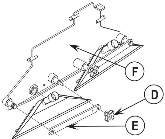
2 Loosen the Black Knob (D) on the back of the scrub deck. Lift the Bar (E) up and remove. Slide the vac shoe out of the shoe support weldment (F). Procedure is the same for both vac shoes.
3 Reinstallation is reverse of removal.
CHARGING THE BATTERIES
Charge the batteries each time the machine is used, or whenever the Battery Condition Meter (K) is showing a yellow, red or flashing red indicator light(s).
To Charge the Batteries...
1 Depress the Battery Disconnect (13).
2 Open the Battery Compartment Cover (16) to provide proper ventilation.
3 Push the connector from the charger into the Battery Connector (22).
4 Follow the instructions on the battery charger.
5 Check the fluid level in all battery cells after charging the batteries. Add distilled water, if necessary, to bring the fluid level up to the bottom of the filler tubes.
WARNING!
Do not fill the batteries before charging.
Only charge batteries in a well-ventilated area.
Do not smoke while servicing the batteries.
CAUTION!
To avoid damage to floor surfaces, always wipe water and acid from the top of the batteries after charging.
CHECKING THE BATTERY ELECTROLYTE LEVEL
Check the electrolyte level of the batteries at least once a week.
After charging the batteries, remove the vent caps and check the electrolyte level in each battery cell. Use distilled water to fill the batteries to the bottom of the filler tube.
Do not over-fill the batteries!
CAUTION!
Acid can spill onto the floor if the batteries are overfilled.
Tighten the vent caps. If there is acid on the batteries, wash the tops of the batteries with a solution of baking soda and water (2 tablespoons of baking soda to 1 quart of water).
View from left rear of machine
Ansicht der Maschine von links hinten
Vue arrêté gauche de la machine
Zicht linker achterkant van machine
| GENERAL MACHINE TROUBLESHOOTING | ||
| Problem | Possible Cause | Remedy |
| Poor water pick-up | Recovery bladder full | Empty recovery bladder |
| Recovery bladder drain hose leak | Secure drain hose cap or replace | |
| Recovery tank cover gasket leak | Replace gasket / Seat cover properly | |
| Debris caught in vacuum shoes | Clean vacuum shoes | |
| Vacuum hose clogged | Remove debris | |
| Foam filter cover not seated | Seat cover properly | |
| Poor extracting performance | Worn brushes | Rotate or replace brushes |
| Wrong cleaning chemical | Consult Nilfisk | |
| Moving machine too fast | Slow down | |
| Inadequate solution flow or no solution | Solution tank empty | Fill solution tank |
| Solution lines, valves, filter, or spray jets clogged | Flush lines and clean solution filter & spray jets | |
| Solution control valve is in closed position | Place control valve handle in open position | |
| Solution solenoid valves | Clean or replace valves | |
| Machine does not run | Emergency stop switch tripped | Reconnect battery connectors |
| Operator seat safety switch | Check for open circuit and replace | |
| Main system controller | Check for error fault codes (see service manual) | |
| Tripped 10 Amp circuit breaker | Check for electrical short circuit & reset | |
| No FWD/REV wheel drive | Drive system speed controller | Check for error fault codes (see service manual) |
| Tripped 45 Amp circuit breaker | Check for drive motor overload | |
| Emergency stop switch tripped | Reconnect battery connectors | |
| Vacuum shuts off and display shows "FULL" when recovery bladder is not full | Plugged vacuum hose(s) | Clear debris |
| Vacuuming large amounts of water at a high travel speed | Slow down or disable auto shut-off feature (see service manual) | |
| Poor Sweeping Performance | Debris Hopper Full | Empty and clean hopper |
| Brushes worn | Replace brushes | |
| Bristles have taken a set | Rotate brushes | |
| No Detergent Flow (EDS models only) | Empty detergent cartridge | Fill detergent cartridge |
| Plugged or kinked detergent flow line | Purge system, straighten lines to remove any kinks | |
| Dry seal cap on detergent cartridge not sealed | Reseat dry seal cap | |
| Detergent ratio slider magnet missing | Replace slider | |
| Detergent pump wiring disconnected or backwards | Connect or reconnect wiring | |
TECHNICAL SPECIFICATIONS (as installed and tested on the unit)
| Model | BRX 700, BRX 700 EDS | |
| Model No. | 56314019, 56316516 | |
| Current | A | 65 |
| Voltage, Batteries | V | 36V |
| Battery Capacity | Ah | 238 |
| Protection Grade | IPX3 | |
| Sound Power Level | ||
| (IEC 60335-2-72: 2002 Amend. 1:2005, ISO 3744) | dB(A)/20μPa | 73 |
| Gross Weight | Ibs / kg | 1570 / 712 |
| Vibrations at the Hand Controls (ISO 5349-1) | m/s2 | <2.5m/s2 |
| Vibrations at the Seat (EN 1032) | m/s2 | <0.5m/s2 |
| Gradeability | ||
| Transport | 14% (8°) | |
| Cleaning | 10% (6°) |
INHALTSÜBERSICHT
Seite
Einleitung. B-2
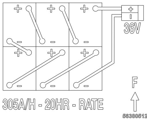
CAUTION: Before changing batteries consult TSBUS2008-984 or visit http://www.nilfisk-advance.com
CAUTION: Before changing batteries consult TSBUS2008-984 or visit http://www.nilfisk-advance.com
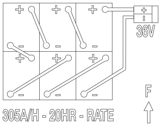
56380512
REMPLISSAGE DU RÉSERVOIR DE SOLUTION
ENLEVEMENT DES BROSSES
CAUTION: Before changing batteries consult TSBUS2008-984 or visit http://www.nilfisk-advance.com
SCHOONWATERTANK VULLEN
Larry Doerr, Vice President Operations
Nilfisk-Advance A/S
Sognevej 25
DK-2605 Brøndby, Denmark
Nilfisk-Advance, Inc.
14600 21st Avenue North
Plymouth, MN 55447 USA
- Prepare the Machine for Use
- INTRODUCTION
- PARTS AND SERVICE
- NAME PLATE
- UNCRATE THE MACHINE
- CAUTIONS AND WARNING
- SYMBOLS
- DANGER!
- WARNING!
- CAUTION!
- GENERAL SAFETY INSTRUCTIONS
- SAVE THESE INSTRUCTIONS
- KNOW YOUR MACHINE
- CONTROL PANEL
- DESCRIPTION OF THE BATTERY CONDITION INDICATORS
- INDICATOR VOLTAGE LEVELS FOR STANDARD CUTOUT LEVEL (AS SHIPPED)
- INDICATOR VOLTAGE LEVELS FOR ALTERNATE CUTOUT LEVEL
- INSTALL THE BATTERIES
- When Servicing Batteries...
- FILLING THE SOLUTION TANK
- BEFORE USING THE BRX 700
- PRE-SPRAYING THE CARPET
- PLAN FOR CLEANING
- DETERGENT (EDS) SYSTEM PREPARATION AND USE
- COMMON INSTRUCTIONS:
- To Purge When Changing Chemicals:
- To Purge Weekly:
- General Use:
- DISPOSABLE CARTRIDGE SPECIFIC INSTRUCTIONS:
- NON- DISPOSABLE CARTRIDGE SPECIFIC INSTRUCTIONS:
- To Extract...
- USING ATTACHMENTS
- AFTER USE
- MAINTENANCE SCHEDULE
- SPRAY NOZZLE MAINTENANCE
- LUBRICATING THE MACHINE
- CLEANING THE VACUUM MOTOR FILTERS
- REMOVING THE BRUSHES
- CHARGING THE BATTERIES
- CHECKING THE BATTERY ELECTROLYTE LEVEL
- INHALTSÜBERSICHT
- REMPLISSAGE DU RÉSERVOIR DE SOLUTION
- ENLEVEMENT DES BROSSES
- SCHOONWATERTANK VULLEN
Brand : NILFISK
Model : BRX 700 EDS
Category : Pressure washer