
ALTIVAR 31 - Speed controller TELEMECANIQUE - Free user manual and instructions
Find the device manual for free ALTIVAR 31 TELEMECANIQUE in PDF.
User questions about ALTIVAR 31 TELEMECANIQUE
0 question about this device. Answer the ones you know or ask your own.
Ask a new question about this device
Download the instructions for your Speed controller in PDF format for free! Find your manual ALTIVAR 31 - TELEMECANIQUE and take your electronic device back in hand. On this page are published all the documents necessary for the use of your device. ALTIVAR 31 by TELEMECANIQUE.
USER MANUAL ALTIVAR 31 TELEMECANIQUE
SECTION 1: INTRODUCTION
Product Range 7
About This Document 7
Hazard Categories and Special Symbols 8
Product Support 8
Start-Up Overview 9
Preliminary Recommendations 10
Precautions 10
Starting from Line Power 11
Power Up after a Manual Fault Reset or Stop Command 11
Test on a Low Power Motor or without a Motor 11
Using Motors in Parallel 11
Operation on an Impedance Grounded System 11
Programming Recommendations 11
Factory Settings 12
Drive Thermal Protection 13
Ventilation 13
Motor Thermal Protection 14
SECTION 2: PROGRAMMING
Drive Keypad Display 16
ATV31...Controllers 16
ATV31A Controllers 16
Key Functions 17
nSt: Freewheel Stop 17
Remote Keypad Display 18
Saving and Loading Configurations 18
Accessing the Menus 19
Accessing the Parameters 20
bFr Parameter 20
Function Compatibility 21
Logic and Analog Input Application Functions 22
SECTION 3: MENUS
Settings Menu SEt- 25
Drive Control Menu drC- 29
I/O Menu I-O- 33
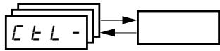
Control Menu CtL- 36
Control Channels 36
Parameter LAC 37
Parameter LAC = L1 or L2 38
Parameter LAC = L3 39
Reference Channel for LAC = L1 or 41
Control Channel for LAC = L1 or L2 42
Reference Channel for LAC = L3 43
Control Channel for LAC = L3:
CHCF = SIM, Combined Reference and Control 44
Control Channel for LAC = L3:
CHCF = SEP, Mixed Mode (Separate Reference and Control) 45
Application Functions Menu FUn- 50
Summing Inputs 56
Preset Speeds 57
+/- Speed 61
PI Regulator 64
Manual-Automatic Operation with PI Regulator 66
Brake Control 70
Management of Limit Switches 76
Fault Menu FLt- 78
Drive Controller Does Not Start, No Fault Displayed 87
Clearing Faults 88
Faults Which Cannot Be Automatically Reset 88
Faults Which Can Be Automatically Reset 89
Faults That Reset When the Fault Is Cleared 90
Configuration Settings Tables 90
Drive Controller and Customer ID 91
1st level Adjustment Parameter 91
Settings Menu 91
Drive Control Menu 92
I/O Menu 92
Control Menu 92
Application Functions Menu 93
Application Functions Menu 94
Fault Menu 95
Communication Menu 95
Index of Parameter Codes 96
Index of Functions 97
SECTION 1: INTRODUCTION
PRODUCT RANGE
The Altivar 31 (ATV31) family of adjustable frequency AC drive controllers is used for controlling three-phase asynchronous motors. The controllers range from:
0.25 to 3 hp (0.18 to 2.2kW ), 208/230/240 V, single-phase input
0.25 to 20 hp (0.18 to 15 kW), 208/230/240 V, three-phase input
0.5 to 20 hp (0.37 to 15kW 400/460/480 V, three-phase input
1 to 20 hp (0.75 to 15kW ), 525/575/600 V, three-phase input
Some ATV31 controllers are available with a reference potentiometer, a run button, and a stop/reset button. These controllers are designated as ATV31-----A controllers throughout this manual. The symbol “ ” in a catalog number designates parts of the number that vary with the rating.
ABOUT THIS DOCUMENT
This manual contains programming instructions for ATV31 drive controllers. The following documentation is also provided with the controller:
- Altivar 31 Installation Manual, VVDED303041US
- Altivar 31 Start-Up Guide, VVDED303043US
Refer to the ATV31 Installation Manual for instructions on receiving, inspection, mounting, installation, and wiring. Refer to the ATV31 Start-Up Guide for instructions on bringing the drive controller into service with the factory configuration.
Refer to the Index of Parameter Codes and the Index of Functions on pages 96-97 of for an alphabetical index of the codes and functions discussed in this manual.
NOTE: Throughout this manual, and on the drive keypad display, a dash appears after menu and sub-menu codes to differentiate them from parameter codes. For example, SET- is a menu, but ACC is a parameter.
HAZARD CATEGORIES AND SPECIAL SYMBOLS
The following symbols and special messages may appear in this manual or on the equipment to warn of potential hazards.
A lightening bolt or ANSI man symbol in a "Danger" or "Warning" safety label on the equipment indicates an electrical hazard which will result in personal injury if the instructions are not followed.
An exclamation point symbol in a safety message in the manual indicates potential personal injury hazards. Obey all safety messages introduced by this symbol to avoid possible injury or death.
| Symbol | Name |
| Lightening Bolt | |
| ANSI Man | |
| Exclamation Point |
DANGER
DANGER indicates an imminently hazardous situation which, if not avoided, will result in death or serious injury.
WARNING
WARNING indicates a potentially hazardous situation which, if not avoided, can result in death or serious injury.
CAUTION
CAUTION indicates a potentially hazardous situation which, if not avoided, can result in minor or moderate injury.
CAUTION
CAUTION, used without the safety alert symbol, indicates a potentially hazardous situation which, if not avoided, can result in property damage.
PRODUCT SUPPORT
For support and assistance, contact the Product Support Group. The Product Support Group is staffed from 8:00 am until 6:00 pm Eastern time to assist with product selection, start-up, and diagnosis of product or application problems. Emergency phone support is available 24 hours a day, 365 days a year.
Telephone 919-266-8600
Toll Free 888-Square D (888-778-2733)
E-mail drive/products/support@us.schneider-electric.com
Fax 919-217-6508
START-UP OVERVIEW
The following procedure is an overview of the minimum steps necessary for bringing an ATV31 drive controller into service. Refer to the ATV31 Installation Manual for the mounting, wiring, and bus voltage measurement steps. Refer to the appropriate sections of this manual for the programming steps.
- Mount the drive controller. Refer to the ATV31 Installation Manual.
-
Make the following connections to the drive controller. Refer to the ATV31 Installation Manual:
-
Connect the grounding conductors.
- Connect the line supply. Ensure that it is within the voltage range of the drive controller.
-
Connect the motor. Ensure that its rating corresponds to the drive controller's voltage.
-
Power up the drive controller, but do not give a run command.
-
Configure bFr (motor nominal frequency) if it is other than 50Hz . bFr appears on the display the first time the drive controller is powered up. It can be accessed in the drC- menu (page 29) anytime.
- Configure the parameters in the drC- menu if the factory configuration is not suitable. Refer to page 12 for the factory settings.
- Configure the parameters in the I-O-, CtL-, and FUn- menus if the factory configuration is not suitable. Refer to page 12 for the factory settings.
-
Configure the following parameters in the SET- menu (pages 25-29):
-
ACC (acceleration) and dEC (deceleration)
LSP (low speed when the reference is zero) and HSP (high speed when the reference is at its maximum)
— ItH (motor thermal protection) -
Remove power from the drive controller and follow the bus voltage measurement procedure in the ATV31 Installation Manual. Then connect the control wiring to the logic and analog inputs.
- Power up the drive controller, then issue a run command via the logic input (refer to the ATV31 Start-Up Guide).
- Adjust the speed reference.
PRELIMINARY RECOMMENDATIONS
Precautions
Before powering up and configuring the drive controller, read and observe the following precautions.
DANGER
- Before powering up and configuring the drive controller, ensure that the logic inputs are switched off (State 0) to prevent unintended starting.
- An input assigned to the run command may cause the motor to start immediately upon exiting the configuration menus.
Failure to follow these instructions will result in death or serious injury.
WARNING
LOSS OF CONTROL
- The designer of any control scheme must consider the potential failure modes of control paths and, for certain critical control functions, provide a means to achieve a safe state during and after a path failure.
- Examples of critical control functions are Emergency Stop and Overtravel Stop.
- Separate or redundant control paths must be provided for critical control functions.
Failure to follow these instructions can result in death, serious injury, or equipment damage.
CAUTION
DAMAGED EQUIPMENT
Do not operate or install any drive controller that appears damaged.
Failure to follow this instruction can result in equipment damage.
| Starting from Line Power | If you are starting the drive controller from line power, ensure that parameter tCt is not set to tn (see page 33), and limit operations of the line contactor to fewer than one per minute to avoid premature failure of the filter capacitors and precharge resistors. The recommended method of control is through inputs LI1 to LI6. The motor thermal state memory returns to zero when line power is removed from the drive controller. |
| Power Up after a Manual Fault Reset or Stop Command | If parameter tCt is at its factory setting (tn), when the drive controller is powered up after a manual fault reset or a stop command, the forward, reverse, and DC injection stop commands must be reset for the drive controller to start. If they are not reset, the drive controller will display nSt and will not start. If automatic restart is configured (parameter Atr in the FLt- menu, see page 79) the reset is not necessary. |
| Test on a Low Power Motor or without a Motor | With the factory configuration, motor phase loss detection (OPL) is active. To check the drive controller in a test or maintenance environment without having to switch to a motor with the same rating as the drive controller, disable motor phase loss detection and configure the voltage/frequency ratio (UFt) to L, constant torque (see page 31). The drive controller will not provide motor thermal protection if the motor current is less than 0.2 times the nominal drive current. |
| Using Motors in Parallel | When using motors in parallel, configure the voltage/frequency ratio, UFt, to L (constant torque) and provide an alternate means of thermal protection on every motor. The drive controller cannot provide adequate motor thermal protection for each motor. |
| Operation on an Impedance Grounded System | When using the drive controller on a system with an isolated or impedance grounded neutral, use a permanent insulation monitor compatible with nonlinear loads. ATV31********M21 and N4 drive controllers feature built-in radio frequency interference (RFI) filters which have capacitors to ground. These filters can be disconnected from ground when using the drive controller on an impedance grounded system to increase the operating life of their capacitors. Refer to the ATV31 Installation Manual for more information. |
| Programming Recommendations | Refer to “Start-Up Overview” on page 9 for the minimum programming steps necessary for bringing the drive controller into service. Use the configuration settings tables beginning on page 91 to prepare and record the drive configuration before programming the drive controller. It is always possible to return to the factory settings by setting the FCS parameter to Inl in the drC-, I-O-, CtL-, or FUn- menus. See pages 32, 35, 49, and 77. When first commissioning an ATV31 drive controller for a 60 Hz system, perform a factory parameter reset. Be sure to set bFr to 60 Hz. We recommend using the auto-tuning function to optimize the drive controller's accuracy and response time. Auto-tuning measures the stator resistance of the motor to optimize the control algorithms. See page 31. |
FACTORY SETTINGS
The ATV31 drive controller is supplied ready for use in most applications, with the factory settings shown in Table 1.
Table 1: Factory Settings
| Function | Code | Factory Setting |
| Display | — | r d y with motor stopped, motor frequency (for example, 50 Hz) with motor running |
| Motor frequency | bFr | 50 Hz |
| Type of voltage/frequency ratio | UFt | n: sensorless flux vector control for constant torque applications |
| Normal stop mode | Stt | 5 E n: normal stop on deceleration ramp |
| Stop mode in the event of a fault | EPL | y E 5: freewheel stop |
| Linear ramps | ACC, dEC | 3 seconds |
| Low speed | LSP | 0 Hz |
| High speed | HSP | 50 Hz |
| Frequency loop gain | FLG, StA | Standard |
| Motor thermal current | lth | Nominal motor current (value depends on the drive controller rating) |
| DC injection braking | SdC | 0.7 x nominal drive controller current for 0.5 seconds |
| Deceleration ramp adaptation | brA | y E 5: automatic adaptation of the deceleration ramp in the event of overvoltage on braking |
| Automatic restart | Atr | n D: no automatic restart after a fault |
| Switching frequency | SFr | 4 kHz |
| Logic inputs | LI1, LI2 | 2-wire transition detection control: LI1 = forward, LI2 = reverse. Not assigned on ATV31********A1 drive controllers |
| LI3, LI4 | 4 preset speeds: speed 1 = speed reference or LSP (see page 26) speed 2 = 10 Hz speed 3 = 15 Hz speed 4 = 20 Hz | |
| LI5, LI6 | Not assigned | |
| Analog inputs | AI1 | Speed reference 0–10 V. Not assigned on ATV31********A1 drive controllers. |
| AI2 | Summed speed reference input 0 ±10 V | |
| AI3 | 4–20 mA, not assigned | |
| Relays | R1 | The contact opens in the event of a fault or if power is removed from the drive controller. |
| R2 | Not assigned | |
| Analog output | AOC | 0–20 mA, not assigned |
1 ATV31-----A range drive controllers have a reference potentiometer, a run button, and a stop/reset button. They are factory set for local control with the run button, the stop/reset button, and the reference potentiometer active. Logic inputs LI1 and LI2 and analog input AI1 are inactive (not assigned).
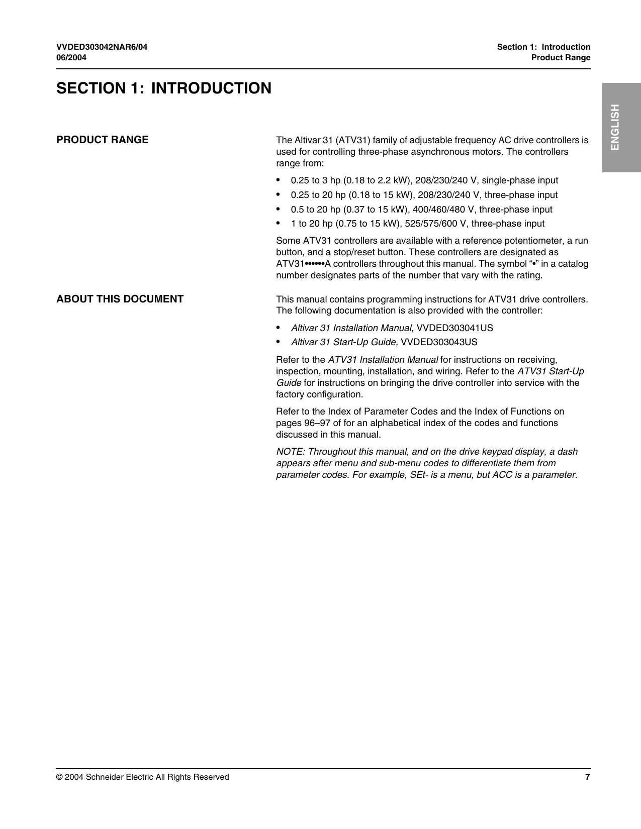
DRIVE THERMAL PROTECTION
Thermal protection of the drive controller is achieved with a positive temperature coefficient (PTC) resistor on the heatsink or power module. In the event of an overcurrent, the drive controller trips to protect itself against overloads. Typical tripping points are:
- Motor current is 185% of nominal drive controller current for 2 seconds
- Motor current is 150% of nominal drive controller current for 60 seconds
Time (seconds)
Ventilation
The fan starts when the drive controller is powered up, but stops after 10 seconds if a run command is not received. The fan starts automatically when the drive controller receives an operating direction and reference. It stops a few seconds after motor speed is less than 0.2Hz and injection braking is completed.
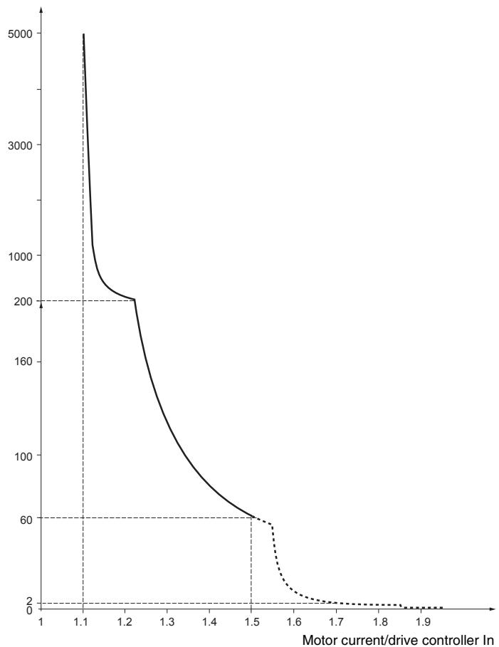
MOTOR THERMAL PROTECTION
Motor thermal protection is achieved by continuous calculation of l^2 t . The protection is available for self-cooled motors.
NOTE: The motor thermal state memory returns to zero when line power is removed from the drive controller.
CAUTION
INADEQUATE MOTOR THERMAL PROTECTION
The use of external overload protection is required under the following conditions:
Starting from line power
- Running multiple motors
- Running motors rated at less than 0.2 times the nominal drive current
- Using motor switching
Failure to follow this instruction can result in equipment damage.
Refer to "Preliminary Recommendations" on pages 10-11 for more information about external overload protection.
SECTION 2: PROGRAMMING
DANGER
UNQUALIFIED USER
- This equipment must be installed, programmed, and serviced only by qualified personnel.
- The application of this product requires expertise in the design and programming of control systems. Only persons with such expertise should be allowed to program, install, alter, and apply this product.
- Qualified personnel performing diagnostics or troubleshooting that requires electrical conductors to be energized must comply with NFPA 70 E - Standard for Electrical Safety Requirements for Employee Workplaces and OSHA Standards - 29 CFR Part 1910 Subpart S Electrical.
Failure to follow these instructions will result in death or serious injury.
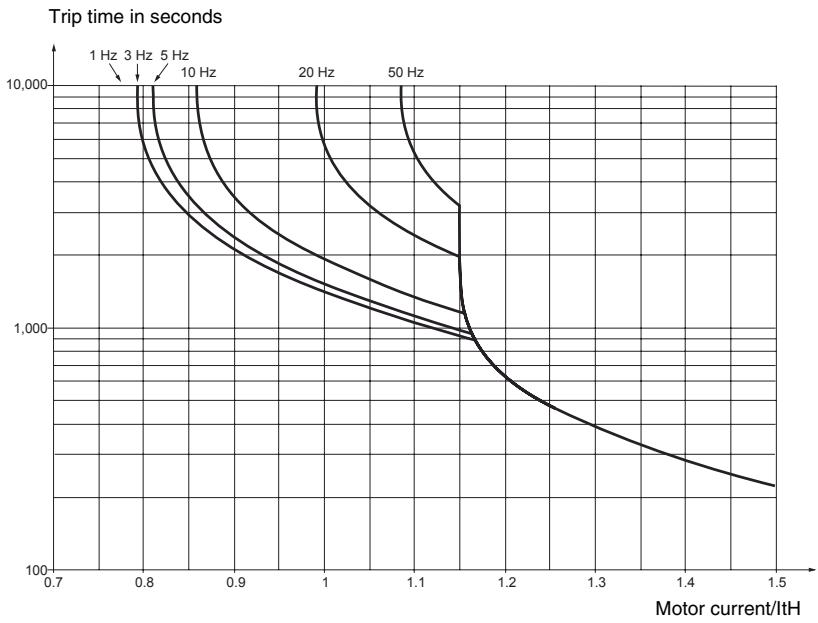
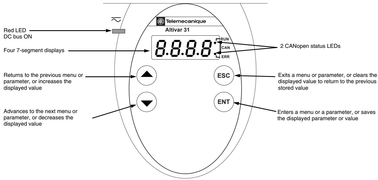
DRIVE KEYPAD DISPLAY
ATV31…Controllers
ATV31A Controllers
ATV31A controllers have a reference potentiometer, a run button, and a stop/reset button.
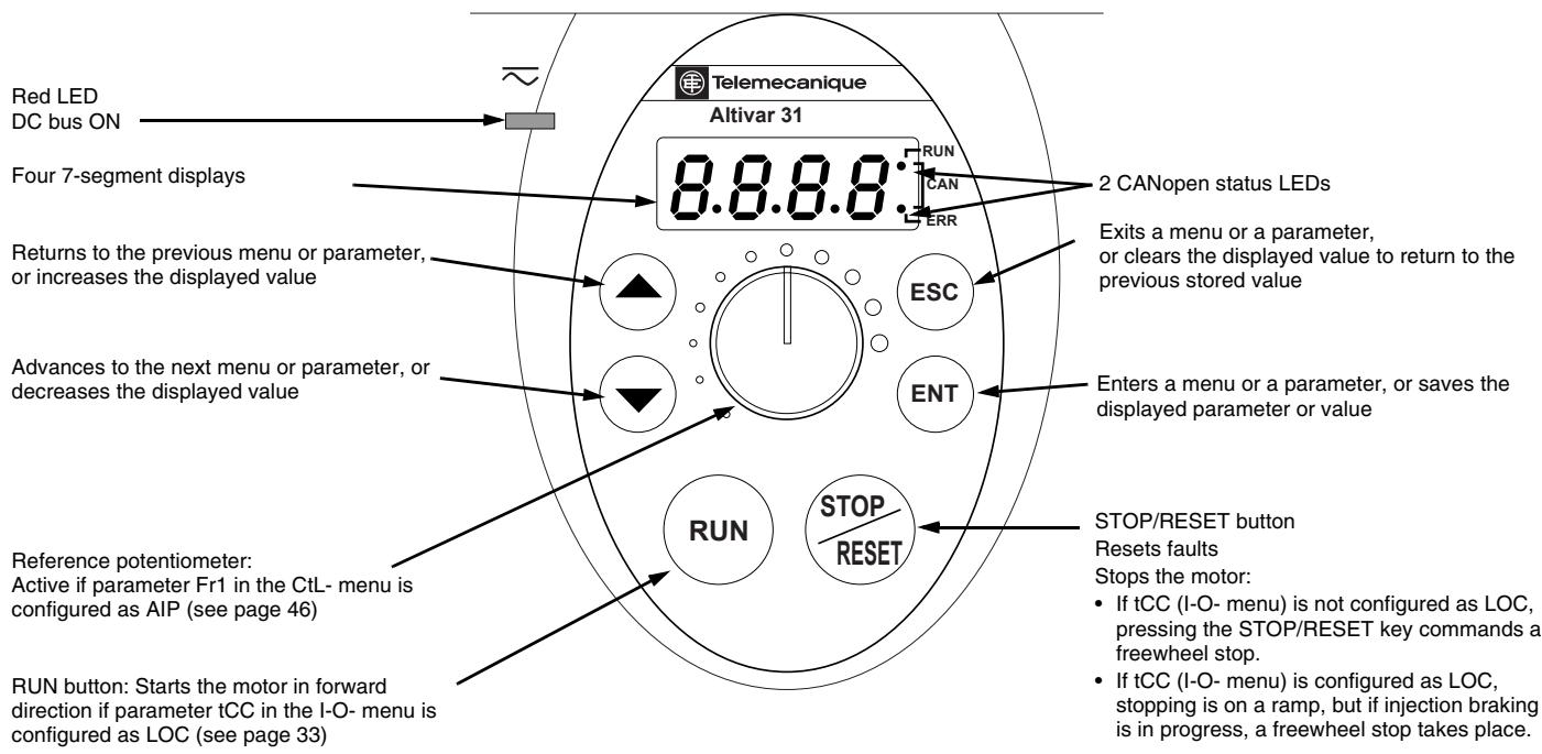
Key Functions
- Press and hold down (longer than 2 seconds) the or keys to scroll through the data quickly.
- Pressing or does not store the selection.
- To store the selection, press the (ENT) key. The display flashes when a value is stored.
A normal display with no fault present and no run command shows:
- The value of one of the display parameters (see page 84). The default display is motor frequency, for example 43.0. In current limiting mode, the display flashes.
- Init: Initialization sequence
- rdY: Drive ready
- dcb: DC injection braking in progress
nSt: Freewheel stop - FSt: Fast stop
tUn: Auto-tuning in progress
If a fault is present, the display flashes.
nSt: Freewheel Stop
If the display shows the code nSt, one of the following conditions is indicated:
- With the factory configuration, when the drive controller is powered up after a manual fault reset or stop command, the forward, reverse, and DC injection stop commands must be reset for the drive controller to start. If they are not reset, the drive controller will display nSt and will not start. If automatic restart is configured, the reset is not necessary.
- If the reference channel or the control channel is assigned to Modbus or CANopen (see page 36), the drive controller will display nSt on power up and remain stopped until the communication bus sends a command.
- If a forward or reverse run command is present when the drive controller is powered up and the drive controller is set for 3-wire control or for 2-wire control with "trn" transition (see page 33) the drive controller will display nSt and will not run until the run command is cycled and a valid speed reference is given.
REMOTE KEYPAD DISPLAY
The optional remote keypad display is a local control unit that can be wall-mounted on the door of an enclosure. It has a cable with connectors for connection to the drive serial link (refer to the manual supplied with the display). The remote keypad display has the same display and programming buttons as the drive controller, with the addition of a switch to lock access to the menu and three buttons for commanding the drive controller:
- FWD/REV commands the direction of rotation.
RUN commands the motor to run. - STOP/RESET commands the motor to stop or resets a fault. Pressing the STOP/RESET button once stops the motor; pressing it a second time stops DC injection braking if it is configured.
In order for the remote keypad display to be active, the tbr parameter in the COM- menu must remain at the factory setting, 19.2 (19,200 bps, see page 82).
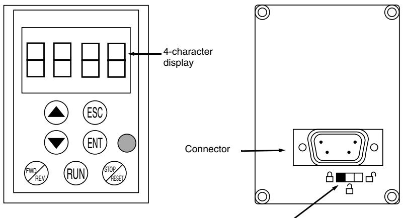
Access locking switch:

settings and display are accessible

- Position:
(SEt- and SUP- menus)

all menus can be accessed
NOTE: Password protection has priority over the access locking switch. See page 86.
Placing the access locking switch in the locked position also prevents the drive settings from being accessed via the drive controller keypad. When the remote keypad display is disconnected, if the access locking switch is in the locked position, the drive controller keypad also remains locked.
Saving and Loading Configurations
Up to four complete configurations can be stored in the remote keypad display and transferred to other drive controllers of the same rating. Four different operations for the same device can also be stored on the terminal. See the SCS and FCS parameters in the drC-, I-O-, CtL-, or FUn- menus. See pages 32, 35, 49, and 77.
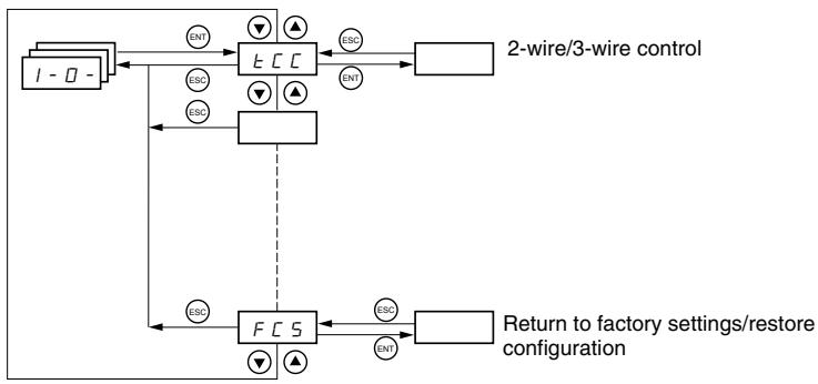
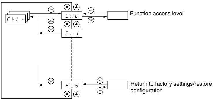
ACCESSING THE MENUS
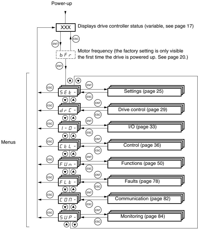
For added convenience, some parameters can be accessed in more than one menu. For example, return to factory settings (FCS) and saving the configuration (SCS) are available in multiple menus.
NOTE: Throughout this guide, a dash appears after menu codes to differentiate them from parameter codes. For example, SET- is a menu, but ACC is a parameter.
ACCESSING THE PARAMETERS
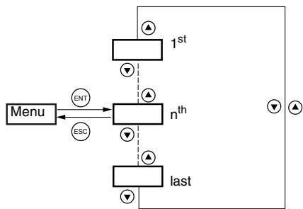
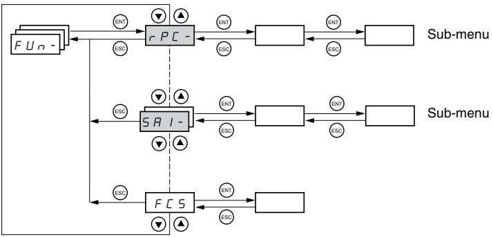
The following figure illustrates how to access parameters and assign their values. To store the parameter value, press the key. The display flashes when a value is stored.
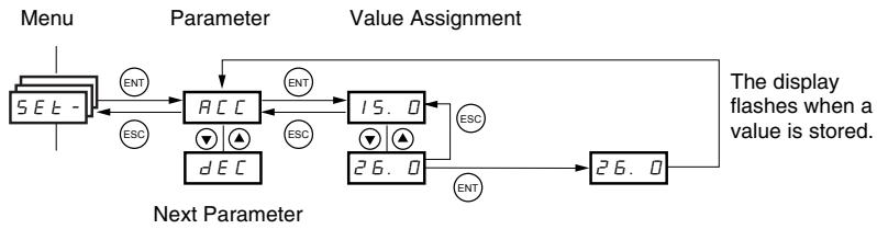
All of the menus are drop-down type menus. Once you have reached the last parameter in a list, press the key to return to the first parameter. From the first parameter in the list, press the key to jump to the last parameter.
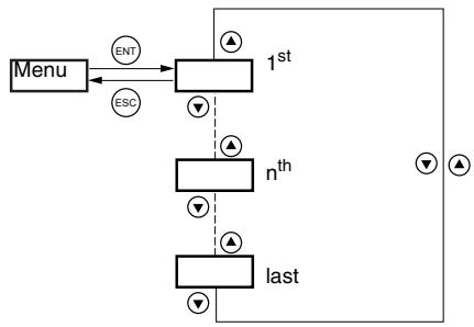
If you have modified a parameter in a menu and you return to that menu without accessing another menu in the meantime, you will be taken directly to the parameter you last modified. See the illustration below. If you have accessed another menu or have restarted the drive controller since the modification, you will be taken to the first parameter in the menu. See the illustration above.
bFr Parameter
Motor frequency, bFr, can only be modified when the drive controller is stopped and not receiving a run command.
| Code | Description | Adjustment range | Factory setting |
| b F r | Motor frequency | 50 or 60 Hz | 50 Hz |
| This is the first parameter displayed when the drive controller is first powered up. bFr can be modified at any time in the drC- menu. Modifying this parameter also modifies the values of the following parameters: HSP (page 26), Ftd (page 29), FrS (page 30), and tFr (page 32). | |||
FUNCTION COMPATIBILITY
Automatic restart, catch on the fly, and reverse direction are only available as described below:
Automatic restart is only available in 2-wire control (tCC = 2C and tCt = LEL or PFO, see page 33).
- Catch on the fly is only available in 2-wire control (tCC = 2C and tCt = LEL or PFO, see page 33). It is deactivated if automatic DC injection braking is configured as DC (AdC = Ct, see page 55).
- Reverse direction is only available on ATV31A controllers if local control is active (tCC = LOC, see page 33).
The choice of application functions is limited by the number of I/O available and by the fact that some functions are incompatible with one another as illustrated in the figure below. Functions which are not listed in the figure are fully compatible. If there is an incompatibility between functions, the first function configured will prevent the others from being configured.
| Summing inputs | +/- Speed1 | Management of limit switches | Preset speeds | PI regulator | Jog operation | Brake sequence | DC injection stop | Fast stop | Freewheel stop | |
| Summing inputs | ● | ↑ | ● | ↑ | ||||||
| +/- Speed1 | ● | ● | ● | ● | ||||||
| Management of limit switches | ● | |||||||||
| Preset speeds | ← | ● | ● | ↑ | ||||||
| PI regulator | ● | ● | ● | ● | ● | ● | ||||
| Jog operation | ← | ● | ← | ● | ● | |||||
| Brake sequence | ● | ● | ● | |||||||
| DC injection stop | ● | ↑ | ||||||||
| Fast stop | ↑ | |||||||||
| Freewheel stop | ← | ← |
1 Excluding a special application with reference channel Fr2 (see pages 41 and 43).

Incompatible functions

Compatible functions

Not applicable

Functions which cannot be active at the same time. The arrow points to the function that has priority.
Stop functions have priority over run commands. Speed references via logic command have priority over analog references.
LOGIC AND ANALOG INPUT APPLICATION FUNCTIONS
Tables 2-5 list the functions that can be assigned to the logic and analog inputs and their factory assignments. A single input can activate several functions at the same time. For example, reverse and second ramp can be assigned to one input. When more than one function is assigned to an input, ensure that the functions are compatible. Use the LIA- and AIA- sub-menus of the SUP- menu (see page 86) to display the functions assigned to the inputs and to check their compatibility.
Table 2: Logic Inputs
| Function | Code | See Page: | Factory Setting | |
| ATV31***** | ATV31*****A | |||
| Not assigned | — | — | LI5-LI6 | LI1-LI2LI5-LI6 |
| Forward | — | — | LI1 | |
| 2 preset speeds | P 5 2 | 58 | LI3 | LI3 |
| 4 preset speeds | P 5 4 | 58 | LI4 | LI4 |
| 8 preset speeds | P 5 8 | 58 | — | — |
| 16 preset speeds | P 5 16 | 59 | — | — |
| 2 preset PI references | P r 2 | 68 | — | — |
| 4 preset PI references | P r 4 | 68 | — | — |
| + speed | U 5 P | 63 | — | — |
| - speed | d 5 P | 63 | — | — |
| Jog operation | J 0 G | 60 | — | — |
| Ramp switching | r P 5 | 52 | — | — |
| Switching for 2ndcurrent limit | L C 2 | 73 | — | — |
| Fast stop via logic input | F 5 E | 53 | — | — |
| DC injection via logic input | d C I | 53 | — | — |
| Freewheel stop via logic input | n S E | 54 | — | — |
| Reverse | r r 5 | 33 | LI2 | — |
| External fault | E E F | 80 | — | — |
| RESET (fault reset) | r 5 F | 79 | — | — |
| Forced local mode | F L D | 82 | — | — |
| Reference switching | r F C | 47 | — | — |
| Control channel switching | C C S | 48 | — | — |
| Motor switching | C H P | 74 | — | — |
| Limiting of forward motion (limit switch) | L R F | 76 | — | — |
| Limiting of reverse motion (limit switch) | L R r | 76 | — | — |
| Fault inhibit | I n H | 81 | — | — |
Table 3: Analog Inputs
| Function | Code | See Page: | Factory Setting | |
| ATV31***** | ATV31*****A | |||
| Not assigned | — | — | AI3 | AI1 - AI3 |
| Reference 1 | F r I | 46 | AI1 | AIP (potentiometer) |
| Reference 2 | F r 2 | 46 | — | |
| Summing input 2 | 5 R 2 | 56 | AI2 | AI2 |
| Summing input 3 | 5 R 3 | 56 | — | — |
| PI regulator feedback | P I F | 68 | — | — |
Table 4: Analog and Logic Outputs
| Function | Code | See Page: | Factory Setting |
| Not assigned | — | — | AOC/AOV |
| Motor current | ☐Cr | 34 | — |
| Motor frequency | r F r | 34 | — |
| Motor torque | ☐L☐ | 34 | — |
| Power supplied by the drive controller | ☐Pr | 34 | — |
| Drive fault (logic data) | F L E | 34 | — |
| Drive running (logic data) | r U n | 34 | — |
| Frequency threshold reached (logic data) | F E R | 34 | — |
| High speed (HSP) reached (logic data) | F L R | 34 | — |
| Current threshold reached (logic data) | C E R | 34 | — |
| Frequency reference reached (logic data) | S r R | 34 | — |
| Motor thermal threshold reached (logic data) | E S R | 34 | — |
| Brake sequence (logic data) | b L C | 34 | — |
Table 5: Relays
| Function | Code | See Page: | Factory Setting |
| Not assigned | — | — | R2 |
| Drive fault | F L E | 34 | R1 |
| Drive running | r U n | 34 | — |
| Frequency threshold reached | F L R | 34 | — |
| High speed (HSP) reached | F L R | 34 | — |
| Current threshold reached | L E R | 34 | — |
| Frequency reference reached | S r R | 34 | — |
| Motor thermal threshold reached | E S R | 34 | — |
| Brake sequence | b L C | 34 | — |
SECTION 3: MENUS
DANGER
Ensure that changes to the operating settings do not present any danger, especially when making adjustments while the drive controller is running the motor.
Failure to follow these instructions will result in death or serious injury.
CAUTION
MOTOR OVERHEATING
- This drive controller does not provide direct thermal protection for the motor.
- Use of a thermal sensor in the motor may be required for protection at all speeds or loading conditions.
- Consult the motor manufacturer for the thermal capability of the motor when operated over the desired speed range.
Failure to follow these instructions can result in equipment damage.
SETTINGSEMENTSET
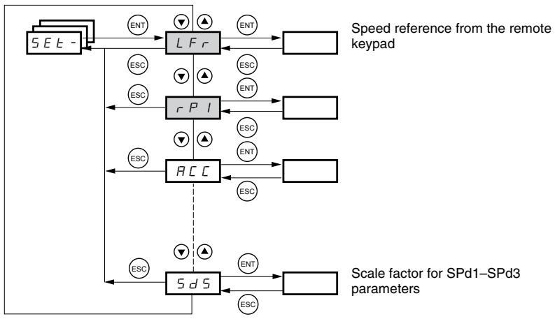
The parameters in the SET- menu can be modified with the drive controller running or stopped. However, we recommend making modifications to the settings with the drive controller stopped.

| Code | Description | Adjustment Range | Factory Setting |
| L F r1 | Speed reference from the remote keypad. | 0 to HSP | |
| This parameter appears if LCC = YES (page 48) or if Fr1/Fr2 = LCC (page 46), and if the remote keypad is online. In this case, LFr can also be accessed via the drive controller keypad.LFr is reset to 0 when the drive controller is powered down. | |||
| r P l' | Internal PI regulator reference See page 64. | 0.0 to 100% | 0 |
| R C C | Acceleration ramp time | 0.1 to 999.9 s | 3 s |
| Defined as the time it takes for the motor to go from 0 Hz to FrS (nominal frequency, see page 30). | |||
| R C 2 | 2ndacceleration ramp time See page 52. | 0.1 to 999.9 s | 5 s |
| d E 2 | 2nddeceleration ramp time See page 52. | 0.1 to 999.9 s | 5 s |
| d E C | Deceleration ramp time | 0.1 to 999.9 s | 3 s |
| Defined as the time it takes for the motor to go from FrS (nominal frequency, see page 30) to 0 Hz.Ensure that dEC is not set too low for the load. | |||
| t R I | Start of custom acceleration ramp, rounded as a percentage of total ramp time (ACC or AC2) See page 51. | 0 to 100 | 10% |
| t R 2 | End of custom acceleration ramp, rounded as a percentage of total ramp time (ACC or AC2) See page 51. | 0 to (100-tA1) | 10% |
| t R 3 | Start of custom deceleration ramp, rounded as a percentage of total ramp time (dEC or dE2) See page 51. | 0 to 100 | 10% |
| t R 4 | End of custom deceleration ramp, rounded as a percentage of total ramp time (dEC or dE2) See page 51. | 0 to (100-tA3) | 10% |
| L S P | Low speed | 0 to HSP | 0 Hz |
| Minimum reference | |||
| H S P | High speed | LSP to tFr | bFr |
| Maximum reference. Ensure that this setting is suitable for the motor and the application. | |||
| I L H | Current used for motor thermal protection. | 0.2 to 1.5 ln2 | Varies with drive controller rating |
| Set lth to the full-load amperes (FLA) indicated on the motor nameplate.Refer to OLL on page 80 if you wish to suppress motor thermal protection. | |||
1 Also accessible in the SUP- menu.
2 In is the nominal drive controller current indicated on the drive controller nameplate.

These parameters appear regardless of how the other menus have been configured. They only appear in the Settings menu.

These parameters only appear if the corresponding function has been selected in another menu. To facilitate programming, they can also be accessed and adjusted from the menu where the corresponding function is found. A detailed description of these functions can be found on the indicated pages.

| Code | Description | Adjustment Range | Factory Setting | ||
| U F r | IR compensation or voltage boost | 0 to 100% | 20 | ||
| If UFt (page 31) = n or nLd, UFr is IR compensation. If UFt = L or P, UFr is voltage boost. Used to optimize torque at very low speed. Increase UFr if the torque is insufficient. To avoid operating instability, ensure that the value of UFr is not too high for a warm motor. NOTE: Modifying UFt (page 31) will cause UFr to return to the factory setting (20%). | |||||
| FL G | Frequency loop gain | 1 to 100% | 20 | ||
| This parameter can only be accessed if UFt (page 31) = n or nLd. FLG adjusts the speed ramp based on the inertia of the driven load. If the value is too low, the response time is longer. If the value is too high, operating instability can result. | |||||
| Hz 50 40 30 20 10 0 -10 0.1 0.2 0.3 0.4 0.5 t FLG low In this case, increase FLG -10 0 0.1 0.2 0.3 0.4 0.5 t Hz 50 40 30 20 10 0 -10 0.1 0.2 0.3 0.4 0.5 t StA low In this case, increase StA -10 0 0.1 0.2 0.3 0.4 0.5 t Hz 50 40 30 20 10 0 -10 0.1 0.2 0.3 0.4 0.5 t StA correct In this case, reduce StA -10 0 0.1 0.2 0.3 0.4 0.5 t | |||||
| S E R | Frequency loop stability | 1 to 100% | 20 | ||
| This parameter can only be accessed if UFt (page 31) = n or nLd. After a period of acceleration or deceleration, StA adapts the return to a steady state to the dynamics of the machine. If the value is too low, overspeed or operating instability can result. If the value is too high, the response time is longer. | |||||
| Hz 50 40 30 20 10 0 -10 0.1 0.2 0.3 0.4 0.5 t StA low In this case, increase StA -10 0 0.1 0.2 0.3 0.4 0.5 t Hz 50 40 30 20 20 10 0 -10 0.1 0.2 0.3 0.4 0.5 t StA correct In this case, reduce StA -10 0 0.1 0.2 0.3 0.4 0.5 t | |||||
| S L P | Slip compensation | 0 to 150% | 100 | ||
| This parameter can only be accessed if UFt (page 31) = n or nLd. SLP adjusts slip compensation for fine tuning of speed regulation. If the slip setting < actual slip, the motor is not rotating at the correct speed in steady state. If the slip setting > actual slip, the motor is overcompensated and the speed is unstable. | |||||
| I d C | Level of DC injection braking current activated via a logic input or selected as a stop mode.1 | See page 53. | 0 to In (In is the nominal drive controller current indicated on the nameplate). | 0.7 In | |
| I d C | Total DC injection braking time selected as a stop mode.1 | See page 53. | 0.1 to 30 s | 0.5 s | |
| I d C I | Automatic DC injection time | See page 55. | 0.1 to 30 s | 0.5 s | |
| I d C I | Level of automatic DC injection current | See page 55. | 0 to 1.2 In | 0.7 In | |
| I d C I | 2ndautomatic DC injection time | See page 55. | 0 to 30 s | 0 s | |
| I d C I | 2ndlevel of DC injection current | See page 55. | 0 to 1.2 In | 0.5 In | |
1 These settings are not related to the Automatic DC Injection function.

These parameters only appear if the corresponding function has been selected in another menu. To facilitate programming, they can also be accessed and adjusted from the menu where the corresponding function is found. A detailed description of these functions can be found on the indicated pages.

| Code | Description | Adjustment Range | Factory Setting | |
| JPF | Skip frequency | 0 to 500 | 0 Hz | |
| JPF prevents prolonged operation at a frequency range of ±1 Hz around JPF. This function avoids a critical speed which leads to resonance. Setting the function to 0 renders it inactive. | ||||
| JF2 | 2ndskip frequency | 0 to 500 | 0 Hz | |
| JF2 prevents prolonged operation at a frequency range of ±1 Hz around JF2. This function avoids a critical speed which leads to resonance. Setting the function to 0 renders it inactive. | ||||
| JGF | Jog operating frequency | See page 60. | 0 to 10 Hz | 10 Hz |
| rPG | PI regulator proportional gain | See page 68. | 0.01 to 100 | 1 |
| rIG | PI regulator integral gain | See page 68. | 0.01 to 100/s | 1/s |
| FB5 | PI feedback multiplication coefficient | See page 68. | 0.1 to 100 | 1 |
| PIC | Reversal of the direction of correction of the PI regulator | See page 68. | nO - YES | nO |
| rP2 | 2ndpreset PI reference | See page 68. | 0 to 100% | 30% |
| rP3 | 3rdpreset PI reference | See page 68. | 0 to 100% | 60% |
| rPY | 4thpreset PI reference | See page 68. | 0 to 100% | 90% |
| SP2 | 2ndpreset speed | See page 59. | 0 to 500 Hz | 10 Hz |
| SP3 | 3rdpreset speed | See page 59. | 0 to 500 Hz | 15 Hz |
| SP4 | 4thpreset speed | See page 59. | 0 to 500 Hz | 20 Hz |
| SP5 | 5thpreset speed | See page 59. | 0 to 500 Hz | 25 Hz |
| SP6 | 6thpreset speed | See page 59. | 0 to 500 Hz | 30 Hz |
| SP7 | 7thpreset speed | See page 59. | 0 to 500 Hz | 35 Hz |
| SP8 | 8thpreset speed | See page 59. | 0 to 500 Hz | 40 Hz |
| SP9 | 9thpreset speed | See page 59. | 0 to 500 Hz | 45 Hz |
| SP10 | 10thpreset speed | See page 59. | 0 to 500 Hz | 50 Hz |
| SP11 | 11thpreset speed | See page 59. | 0 to 500 Hz | 55 Hz |
| SP12 | 12thpreset speed | See page 59. | 0 to 500 Hz | 60 Hz |
| SP13 | 13thpreset speed | See page 59. | 0 to 500 Hz | 70 Hz |
| SP14 | 14thpreset speed | See page 59. | 0 to 500 Hz | 80 Hz |
| SP15 | 15thpreset speed | See page 59. | 0 to 500 Hz | 90 Hz |
| SP16 | 16thpreset speed | See page 59. | 0 to 500 Hz | 100 Hz |
| CL1 | Current limit | 0.25 to 1.5 In1 | 1.5 In | |
| Used to limit the torque and the temperature rise of the motor. | ||||
| CL2 | 2ndcurrent limit | See page 73. | 0.25 to 1.5 In | 1.5 In |
| LCS | Low speed operating time | 0 to 999.9 s | 0 (no time limit) | |
| After operation at LSP for a defined period, a motor stop is requested automatically. The motor restarts if the frequency reference is greater than LSP and if a run command is still present. | ||||
| rSL | Restart error threshold (wake-up threshold) | See page 69. | 0 to 100% | 0 |
| UFR2 | IR compensation, motor 2 | See page 75. | 0 to 100% | 20 |
| FLG2 | Frequency loop gain, motor 2 | See page 75. | 1 to 100% | 20 |
| SET2 | Stability, motor 2 | See page 75. | 1 to 100% | 20 |
| SLP2 | Slip compensation, motor 2 | See page 75. | 0 to 150% | 100% |
1 In is the nominal drive controller current indicated on the drive controller nameplate.

These parameters only appear if the corresponding function has been selected in another menu. To facilitate programming, they can also be accessed and adjusted from the menu where the corresponding function is found. A detailed description of these functions can be found on the indicated pages.

| Code | Description | Adjustment Range | Factory Setting |
| F t d | Motor frequency threshold above which the relay contact (R1 or R2) closes, or output AOV = 10 V. R1, R2, or dO must be assigned to FtA. | 0 to 500 Hz | bFr |
| t t d | Motor thermal state threshold above which the relay contact (R1 or R2) closes, or output AOV = 10 V. R1, R2, or dO must be assigned to tSA. | 0 to 118% | 100% |
| C t d | Motor current threshold beyond which the relay contact (R1 or R2) closes, or output AOV = 10 V. R1, R2, or dO must be assigned to CtA. | 0 to 1.5 In1 | In1 |
| S d S | Scale factor for display parameter SPd1/SPd2/SPd3 (see SUP- menu on page 85) | 0.1 to 200 | 30 |
| Used to scale a value (such as motor speed) in proportion to the output frequency rFr. If SdS ≤ 1, SPd1 is displayed (possible definition = 0.01). If 1 < SdS ≤ 10, SPd2 is displayed (possible definition = 0.1). If SdS > 10, SPd3 is displayed (possible definition = 1). If SdS > 10 and SdS x rFr > 9999: Display of Spd3 = SdS x rFr / 1000 (to 2 decimal places). For example, if SdS x rFr equals 24,223, the display shows 24.22. If SdS > 10 and SdS x rFr > 65535, the display shows 65.54. Example: Display motor speed for a 4-pole motor, 1500 rpm at 50 Hz (synchronous speed): SdS = 30 SPd3 = 1500 at rFr = 50 Hz | |||
| S F r | Switching frequency See page 32. | 2.0 to 16 kHz | 4 kHz |
| This parameter can also be accessed in the drC- menu. | |||
1 In is the nominal drive controller current indicated on the drive controller nameplate.
DRIVE CONTROL MENU drC-
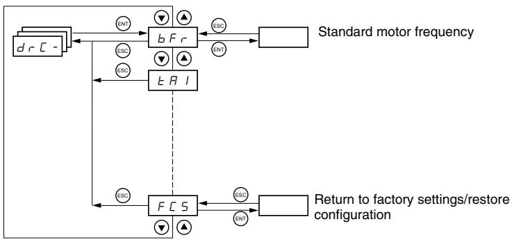
With the exception of tUn, drive control parameters can only be modified when the drive controller is stopped and no run command is present. This menu can be accessed with the access locking switch on the remote keypad display in the position. Drive controller performance can be optimized by:
- Setting the drive control parameters to the values on the motor nameplate
Performing an auto-tune operation (on a standard asynchronous motor)
| Code | Description | Adjustment Range | Factory Setting |
| b Fr | Motor frequency | 50 or 60 Hz | 50 |
| This parameter modifies the presets of the following parameters: HSP (page 26), Ftd (page 29), FrS (page 30), and tFr (page 32). | |||
| U n 5 | Nominal motor voltage indicated on the nameplate | Varies with drive controller rating | Varies with drive controller rating |
| ATV31***M2: 100 to 240 VATV31***M3X: 100 to 240 VATV31***N4: 100 to 500 VATV31***S6X: 100 to 600 V | |||
| F r 5 | Nominal motor frequency indicated on the nameplate | 10 to 500 Hz | 50 Hz |
| The ratio UnS (in volts)FrS (in Hz) must not exceed the following values:ATV31***M2: 7ATV31***M3X: 7ATV31***N4: 14ATV31***S6X: 17NOTE: Changing the setting of bFr to 60 Hz also changes the setting of FrS to 60 Hz. | |||
| n C r | Nominal motor current indicated on the nameplate | 0.25 to 1.5 In1 | Varies with drive controller rating |
| n 5 P | Nominal motor speed indicated on the nameplate | 0 to 32760 rpm | Varies with drive controller rating |
| 0 to 9999 rpm, then 10.00 to 32.76 krpmIf the nameplate indicates synchronous speed and slip (in Hz or as a percentage) instead of nominal speed, calculate nominal speed as follows:Nominal speed = Synchronous speed x 100 - slip as a%or100Nominal speed = Synchronous speed x 50 - slip in Hz50(50 Hz motors)orNominal speed = Synchronous speed x 60 - slip in Hz60(60 Hz motors) | |||
| C D 5 | Motor power factor indicated on the nameplate | 0.5 to 1 | Varies with drive controller rating |
1 In is the nominal drive controller current indicated on the drive controller nameplate.

| Code | Description | Adjustment Range | Factory Setting |
| rSC | Cold state stator resistance | See below. | nO |
| nD: Function inactive. For applications that do not require high performance or do not tolerate automatic auto-tuning (passing a current through the motor) each time the drive is powered up. In lE: Activates the function. Used to improve low-speed performance, whatever the thermal state of the motor. XXXX: Value of cold state stator resistance used, in mΩ NOTE: We recommended that you activate this function for lifting and handling applications. This function should only be activated when the motor is cold. When rSC = lnt, parameter tUn is forced to POn. At the next run command, the stator resistance is measured with an auto-tune. The value of parameter rSC then changes to this measured stator resistance value (XXXX) and is maintained at that value; tUn remains forced to POn. Parameter rSC remains at lnt as long as the stator resistance measurement has not been performed. Value XXX can be forced or modified using the ▲▼ keys. | |||
| tUn | Motor control auto-tuning | See below. | nO |
| Before performing an auto-tune, ensure that all the drive control parameters (UnS, FrS, nCr, nSP, COS) are configured correctly. Parameter tUn can be modified with the drive controller running; however, an auto-tune will only be performed if no run or braking command is present. nD: Auto-tuning is not performed. If E S: Auto-tuning is performed as soon as possible, then the parameter automatically switches to dOnE or, in the event of a fault, to nO. The tnF fault is displayed if tnL = YES (see page 81). dOnE: Auto-tuning is completed and the measured stator resistance will be used to control the motor. rUn: Auto-tuning is performed each time a run command is sent. POn: Auto-tuning is performed each time the controller is powered up. L l l to L l E: Auto-tuning is performed when the logic input assigned to this function transitions from 0 to 1. Note: tUn is forced to POn if rSC is any value other than nO. Auto-tuning will only be performed if no run or braking command is present. If a freewheel stop or fast stop function is assigned to a logic input, this input must be set to 1 (active at 0). Auto-tuning may last for 1 to 2 seconds. Wait for the display to change to dOnE or nO. Interrupting auto-tuning may result in an auto-tuning fault (see page 88) and cause the motor to be improperly tuned. During auto-tuning, the motor operates at nominal current. | |||
| tUS | Auto-tuning status (status information only, cannot be modified) | See below. | tAb |
| E R b: The default stator resistance value is used to control the motor. P E n d: Auto-tuning has been requested but not yet performed. P r D: Auto-tuning is in progress. F R l L: Auto-tuning has failed. d D n E: Auto-tuning is complete. The stator resistance measured by the auto-tuning function is used to control the motor. 5 E r d: Auto-tuning is complete. The cold state stator resistance is used to control the motor (rSC must be other than nO). | |||
| U F E | Selection of the voltage/frequency ratio | See below. | n |
| L: Constant torque (for motors connected in parallel or special motors) P: Variable torque (pump and fan applications) n: Sensorless flux vector control (for constant torque applications) n L d: Energy savings (for variable torque applications not requiring high dynamics. This behaves in a similar way to the P ratio at no load and the n ratio with load.) | |||
| Voltage UnS Frequency L n P FrS | |||
| Code | Description | Adjustment Range | Factory Setting |
| n r d | Random switching frequency | See below. | YES |
| This function randomly modulates the switching frequency to reduce motor noise. | |||
| Y E 5: Frequency with random modulation | |||
| n D: Fixed frequency | |||
| 5 F r | Switching frequency1 | 2.0 to 16 kHz | 4 kHz |
| Adjust this setting to reduce audible motor noise. If the switching frequency is set to a value higher than 4 kHz, in the event of excessive temperature rise, the drive controller automatically reduces the switching frequency. It increases it again when the temperature returns to normal. If the switching frequency is set above the factory setting (4 kHz), refer to the ATV31 Installation Manual for derating curves. | |||
| E F r | Maximum output frequency | 10 to 500 Hz | 60 Hz |
| The factory setting is 60 Hz, or 72 Hz if bFr is set to 60 Hz. | |||
| 5 r F | Suppression of the speed loop filter | See below. | nO |
| n D: The speed loop filter is active (prevents the reference from being exceeded). Y E 5: The speed loop filter is suppressed. In position control applications, this setting reduces the response time, but the reference may be exceeded. | |||
| 50 SSL = nO SSL = YES | |||
| 5 C S | Saving the configuration2 | See below. | nO |
| n D: Function inactive | |||
| 5 E r l: Saves the current configuration (but not the result of auto-tuning) to EEPROM. SCS automatically switches to nO as soon as the save is performed. Use this function to keep another configuration in reserve, in addition to the current configuration. The drive controller is factory set with the current configuration and the backup configuration both initialized to the factory configuration. If the remote keypad display is connected to the drive controller, up to four additional settings are available: F I L l, F I L e, F I L e, and F I L 4. Use these selections to save up to four configurations in the remote keypad display's EEPROM memory. SCS automatically switches to nO as soon as the save is performed. | |||
| F C S | Return to factory settings/Restore configuration2 | See below. | nO |
| n D: Function inactive | |||
| r E C l: Replaces the current configuration with the backup configuration previously saved by SCS (SCS set to Srl). rECI is visible only if the backup configuration has been saved. FCS automatically changes to nO as soon as this action is performed. l n l: Replaces the current configuration with the factory settings. FCS automatically switches to nO as soon as this action is performed. If the remote keypad display is connected to the drive controller, up to four additional selections are available corresponding to backup files loaded in the remote keypad display's EEPROM memory: F I L l, F I L e, F I L e, and F I L 4. These selections replace the current configuration with the corresponding backup configuration in the remote keypad display. FCS automatically changes to nO as soon as this action is performed. Note: If n R d briefly appears on the display once the parameter has switched to nO, the configuration transfer is not possible and has not been performed (because the controller ratings are different, for example). If n E r brieftly appears on the display once the parameter has switched to nO, a configuration transfer error has occurred and the factory settings must be restored using Inl. In both cases, check the configuration to be transferred before trying again. NOTE: For rECI, Inl, and FIL 1 to FIL4 to take effect, you must press and hold down the ENT key for 2 s. | |||
1 This parameter can also be accessed in the Settings menu, SEt-. See page 25.
2 SCS and FCS can be accessed in several configuration menus, but their settings affect all menus and parameters as a whole.
I/O MENU I-O-
I/O parameters can only be modified when the drive controller is stopped and no run command is present. This menu can be accessed with the access locking switch on the remote keypad display in the position.

| Code | Description | Factory Setting |
| E CC | Type of control: 2-wire, 3-wire, or local | 2C ATV31*****A: LOC |
| Control configuration: 2 C = 2-wire control 3 C = 3-wire control L D C = Local control, for ATV31*****A controllers only. This option is not available if parameter LAC = L3 (see page 46). | ||
| 2-wire control (maintained contact): The state of the input (open or closed) controls running or stopping. | ||
| Wiring example: LI1: forward LIX: reverse | ATV31 Controller 24 V LI1 LIX | |
| 3-wire control (pulse control): A forward or reverse pulse is sufficient to control startup. A stop pulse is sufficient to control stopping. Wiring example: LI1: stop LI2: forward LIX: reverse | ATV31 Controller 24 V LI1 LI2 LIX | |
| NOTE: To change the assignment of tCC, press the ENT key for 2 s. This causes the following functions to return to their factory setting: rrS, tCt, and all functions affecting logic inputs. | ||
| E C E | Type of 2-wire control (parameter only accessible if tCC = 2C) | trn |
| L E L: If the forward or reverse input is high when the drive controller is powered up, the drive controller will start the motor. If both inputs are high on power up, the drive controller will run forward. L r n: The forward or reverse input must transition from low to high before the drive controller will start the motor. If the forward or reverse input is high when the drive controller is powered up, the input must be cycled before the drive controller will start the motor. P F D: Same as LEL, but the forward input has priority over the reverse input. If forward is activated while the controller is running in reverse, the drive controller will run in the forward direction. | ||
| r r 5 | Reverse operation via logic input | if tCC = 2C: LI2 if tCC = 3C: LI3 if tCC = LOC: nO |
| If rrS = nO, reverse operation is not assigned to a logic input. Reverse operation may still be commanded by another means, such as negative voltage on AI2, a serial link command, or the remote keypad. n D: Not assigned L I 2: Logic input LI2, can be accessed if tCC = 2C L I 5: Logic input LI5 L I 3: Logic input LI3 L I 6: Logic input LI6 L I 4: Logic input LI4 | ||

| Code | Description | Factory Setting |
| C r L 3 C r H 3 | Value for low speed (LSP) on input Al3, can be set between 0 and 20 mA Value for high speed (HSP) on input Al3, can be set between 4 and 20 mA | 4 mA 20 mA |
| These two parameters are used to configure the input for 0–20 mA, 4–20 mA, 20–4 mA, etc. Frequency Example: 20–4 mA HSP LSP 0 CrL3 CrH3 20 Al 3 (mA) | Frequency HSP LSP 0 CrH3 (4 mA) CrL3 (20 mA) Al 3 (mA) | |
| R D l e | Configuration of the analog output | 0A |
| D R: 0–20 mA configuration (use terminal AOC) 4 R: 4–20 mA configuration (use terminal AOC) 1 D U: 0–10 V configuration (use terminal AOV) | ||
| d D | Analog/logic output AOC/AOV | nO |
| n D: Not assigned D C r: Motor current. 20 mA or 10 V corresponds to twice the nominal drive controller current. r F r: Motor frequency. 20 mA or 10 V corresponds to the maximum frequency tFr (page 32). D E r: Motor torque. 20 mA or 10 V corresponds to twice the nominal motor torque. D P r: Power supplied by the drive. 20 mA or 10 V corresponds to twice the nominal drive controller power. Making the following assignments changes the analog output to a logic output (refer to the ATV31 Installation Manual for more information). With these assignments, configure AOt to 0 A. F L E: Drive fault r U n: Drive running F E R: Frequency threshold reached (Ftd parameter in the SET- menu, page 29) F L R: High speed (HSP) reached C E R: Current threshold reached (Ctd parameter in the SET- menu, page 29) S r R: Frequency reference reached E S R: Motor thermal threshold reached (ttd parameter in the SET- menu, page 29) b L C: Brake sequence (status information only. bLC can be only be activated or deactivated from the FUn- menu, see page 72). R P L: Loss of 4–20 mA signal, even if LFL = nO (page 81) The logic output state is 1 (24 V) when the selected assignment is active, except for FLt which is in state 1 if the drive controller is not faulted. | ||
| r l | Relay R1 | FLt |
| n D: Not assigned F L E: Drive fault r U n: Drive running F E R: Frequency threshold reached (Ftd parameter in the SET- menu, page 29) F L R: High speed (HSP) reached C E R: Current threshold reached (Ctd parameter in the SET- menu, page 29) S r R: Frequency reference reached E S R: Motor thermal threshold reached (ttd parameter in the SET- menu, page 20) R P L: Loss of 4–20 mA signal, even if LFL = nO (page 81) The relay is powered up when the selected assignment is active, except for FLt which is powered up if the drive controller is not faulted. | ||
| r 2 | Relay R2 | nO |
| n D: Not assigned F L E: Drive fault r U n: Drive running F E R: Frequency threshold reached (Ftd parameter in the SET- menu, page 29) F L R: High speed (HSP) reached C E R: Current threshold reached (Ctd parameter in the SET- menu, page 29) S r R: Frequency reference reached E S R: Motor thermal threshold reached (ttd character in the SET- menu, page 29) b L C: Brake sequence (status information only. bLC can be only be activated or deactivated from the FUn- menu, see page 72). R P L: Loss of 4–20 mA signal, even if LFL = nO (page 81) The relay is powered up when the selected assignment is active, except for FLt which is powered up if the drive controller is not faulted. | ||
| Code | Description | Factory Setting |
| SCS | Saving the configuration1 | nO |
| nD: Function inactive 5 E r l: Saves the current configuration (but not the result of auto-tuning) to EEPROM. SCS automatically switches to nO as soon as the save is performed. Use this function to keep another configuration in reserve, in addition to the current configuration. The drive controller is factory set with the current configuration and the backup configuration both initialized to the factory configuration. If the remote keypad display is connected to the drive controller, up to four additional settings are available: F I L 1, F I L 2, F I L 3, and F I L 4. Use these selections to save up to four configurations in the remote keypad display's EEPROM memory. SCS automatically switches to nO as soon as the save is performed. | ||
| FCS | Return to factory settings/restore configuration1 | nO |
| nD: Function inactive r E C l: Replaces the current configuration with the backup configuration previously saved by SCS (SCS set to Strl). rECI is visible only if the backup configuration has been saved. FCS automatically changes to nO as soon as this action is performed. If n D: Replaces the current configuration with the factory settings. FCS automatically switches to nO as soon as this action is performed. If the remote keypad display is connected to the drive controller, up to four additional selections are available corresponding to backup files loaded in the remote keypad display's EEPROM memory: F I L 1, F I L 2, F I L 3, and F I L 4. These selections replace the current configuration with the corresponding backup configuration in the remote keypad display. FCS automatically changes to nO as soon as this action is performed. Note: If n D: briefly appears on the display once the parameter has switched to nO, the configuration transfer is not possible and has not been performed (because the controller ratings are different, for example). If n D: briefly appears on the display once the parameter has switched to nO, a configuration transfer error has occurred and the factory settings must be restored using InI. In both cases, check the configuration to be transferred before trying again. NOTE: For rECI, InI, and FIL1 to FIL4 to take effect, you must press and hold down the ENT key for 2 s. | ||
SCS and FCS can be accessed in several configuration menus, but their settings affect all menus and parameters as a whole.
CONTROL MENU CTL
Control Channels
Control parameters can only be modified when the drive controller is stopped and no run command is present. This menu can be accessed with the access locking switch on the remote keypad display in the position.
Control commands, such as forward and reverse, and speed reference commands can be sent to the drive controller from the sources specified in Table 6. ATV31 drive controllers allow you to assign control and reference sources to separate control channels (Fr1, Fr2, Cd1, or Cd2, see pages 46-47) and to switch between them. For example, you might assign LCC to reference channel 1 and CAn to reference channel 2 and switch between the two reference sources. It is also possible to use separate sources for control and reference commands. This is called mixed mode operation. These functions are explained in detail in the sections beginning on page 38.
Table 6: Control and Reference Sources
| Control Sources (CMD) | Reference Sources (rFr) | ||
| tEr: | Terminal (LI) | Al1, Al2, Al3: | Terminal |
| LOC: | Drive keypad (RUN/STOP) on ATV31-----A controllers only | AIP: | Potentiometer on ATV31-----A only |
| LCC: | Remote keypad display (RJ45 socket) | LCC: | Drive keypad (on ATV31----- and ATV31-----A controllers) or remote keypad display |
| Mdb: | Modbus (RJ45 socket) | Mdb: | Modbus (RJ45 socket) |
| CAN: | CANopen (RJ45 socket) | CAN: | CANopen (RJ45 socket) |
WARNING
The stop buttons on ATV31……A drive controllers and on the remote keypad display can be programmed to not have priority. To retain stop key priority, set PSt to YES (see page 49).
Failure to follow this instruction can result in death, serious injury, or equipment damage.
Parameter LAC
Use parameter LAC (page 46) in the CtL- menu to select levels of function access and to set the control and reference sources.
- LAC = L1: Level 1—access to standard functions. Control and reference commands come from one source. See “Parameter LAC = L1 or L2” on page 38.
-
LAC = L2: Level 2—access to all of the level 1 functions, plus the advanced functions listed below. Control and reference commands come from one source. See “Parameter LAC = L1 or L2” on page 38.
-
+ / - Speed (motorized potentiometer)
— Brake control
Switching for 2nd current limit
Motor switching
Management of limit switches -
LAC = L3: Level 3—access to all of the level 2 functions. Control and reference commands can come from separate sources. See “Parameter LAC = L3” on page 39.
Parameter LAC = L1 or L2
If parameter LAC is set to L1 or L2, the control and reference commands come from one source. The possible control and reference sources, and the settings that specify them, are:
- Control and reference via the input terminals or the drive keypad display in forced local (see FLO on page 82)
Control and reference via the Modbus serial link
Control and reference via the CANopen serial link - Control and reference via the remote keypad display (see LCC on page 48)
NOTE: Modbus or CANopen is selected online by writing the appropriate control word (refer to the protocol-specific documentation).
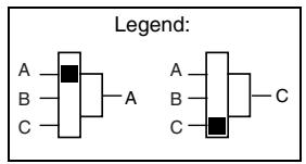
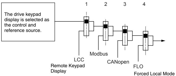
The diagram below illustrates the order of priority when more than one control and reference source is specified. In the diagram, information flows from left to right. At step 1, LCC is not set to YES to enable the remote keypad display, so the drive keypad display is selected as the control and reference source. At steps 2-4, Modbus, CANopen, and forced local control are not set to YES, so the drive keypad display remains the selected source. The order of priority, therefore, is forced local, CANopen, Modbus, and the drive keypad display or the remote keypad display. For example, if forced local mode were enabled, it would have priority over any other setting. Similarly, if CANopen were enabled, it would have priority over any other setting except for FLO. Refer to the diagrams on pages 41 and 42 for more detail.
- On ATV31 drive controllers with the factory configuration, control and reference commands come from the control terminals.
- On ATV31-A drive controllers with the factory configuration, control commands come from the drive keypad display and reference commands come from a summation of the reference potentiometer and AI1 on the control terminals.
- With a remote keypad display, if LCC = YES (see page 48), control and reference commands come from the remote keypad display. The reference frequency is set by parameter LFr in the SET- menu (see page 26).
Parameter LAC = L3
If parameter LAC is set to L3:
- The control and reference channels can be combined (parameter CHCF = SIM, see page 47), or
- The control and reference channels can be separate (parameter CHCF = SEP , see page 47)
Parameter CHCF = SIM
The following figure illustrates combined control and reference sources:
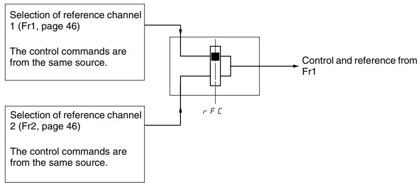
Use parameter rFC (page 47) to select reference channel Fr1 or Fr2, or to configure a logic input or a control word bit for remote switching between the two channels. Refer to the diagram on page 44.
Parameter CHCF = SEP
The following figures illustrate separate control and reference channels (parameter CHCF = SEP).
Separate Reference Channels:
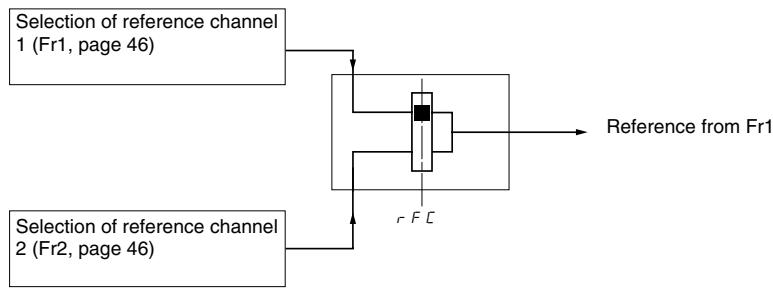
Use parameter rFC (page 47) to select reference channel Fr1 or Fr2, or to configure a logic input or a control word bit for remote switching between the two channels.
Separate Control Channels:
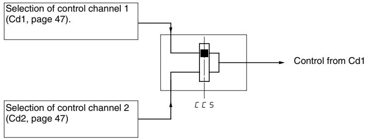
Use parameter CCS (page 48) to select control channel Cd1 or Cd2, or to configure a logic input or a control word bit for remote switching between the two channels.
Reference Channel for LAC = L1 or L2
Legend:

Function accessible if LAC = L2
Control Channel for LAC = L1 or L2
The settings of parameters FLO, LCC, and the selection of Modbus or CANopen protocol determine both the reference and control channels. The order of priority is FLO, CANopen, Modbus, and LCC.
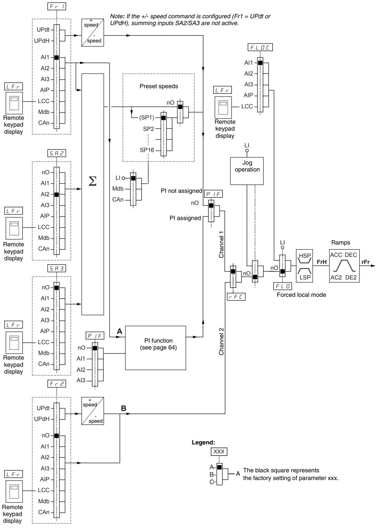
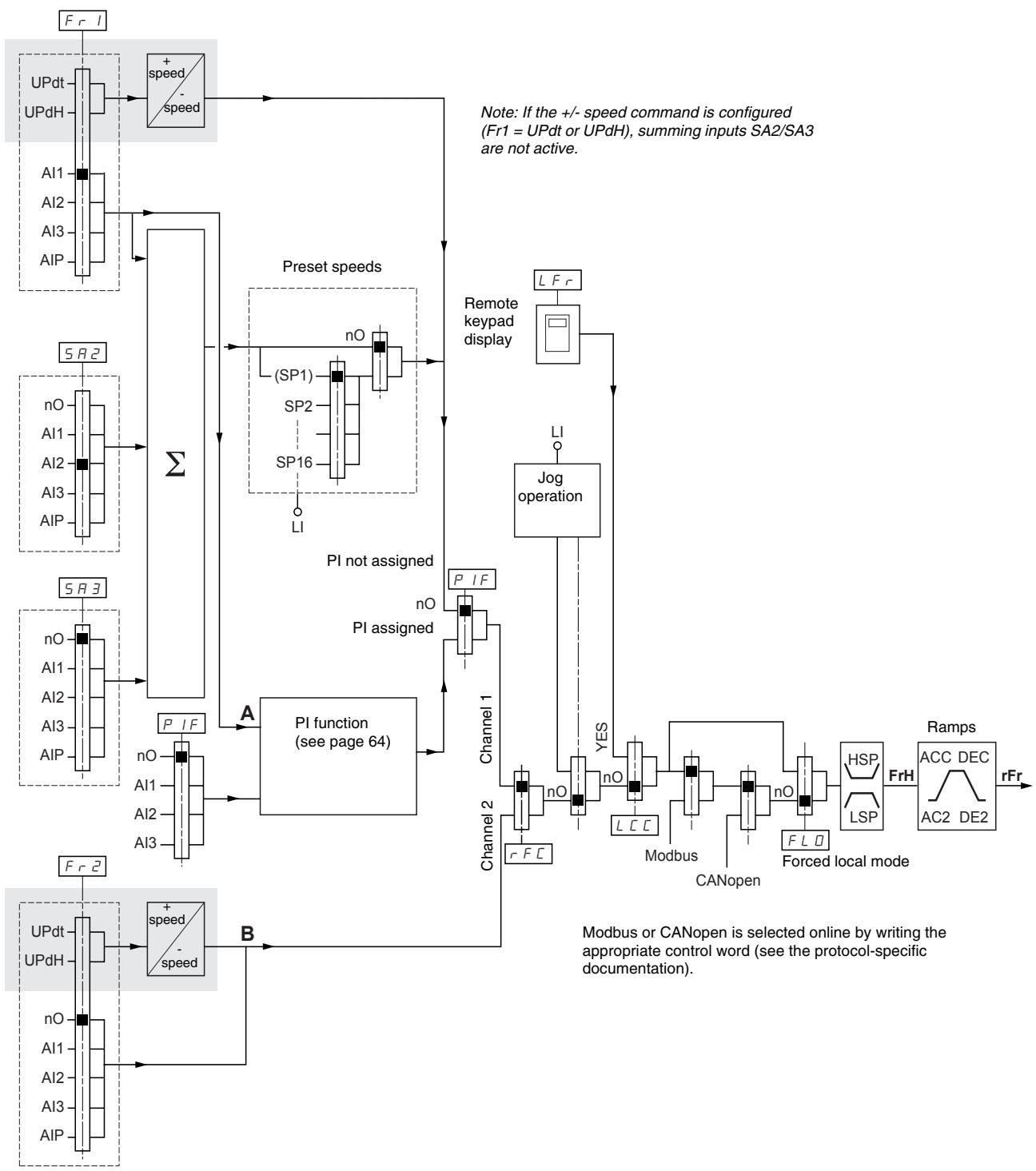
Reference Channel for LAC = L3
Control Channel for LAC = L3: CHCF = SIM, Combined Reference and Control
If CHCF is set to SIM (see page 47), parameters Fr1, Fr2, FLO, and FLOC determine both the reference and control source. For example, if the reference is via the analog input on the terminal block, control is via the logic input on the terminal block.
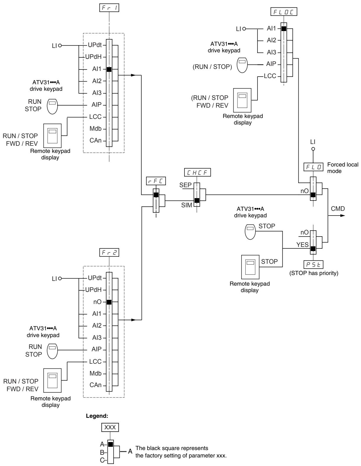
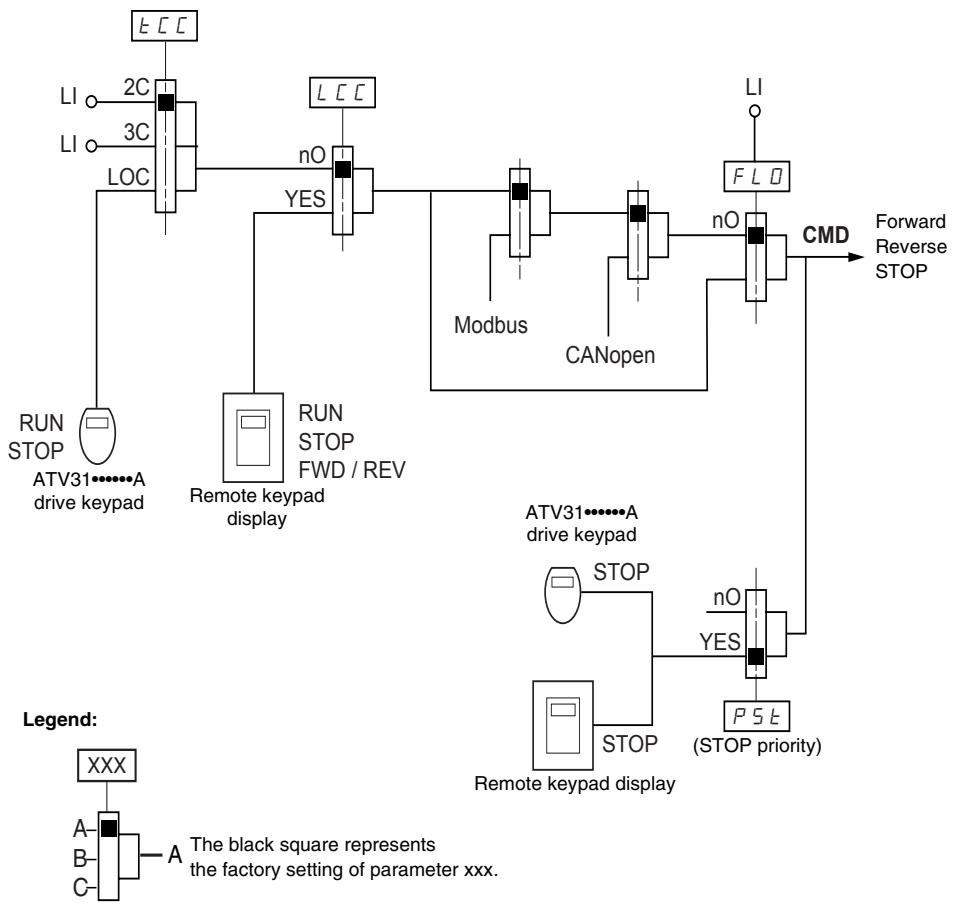
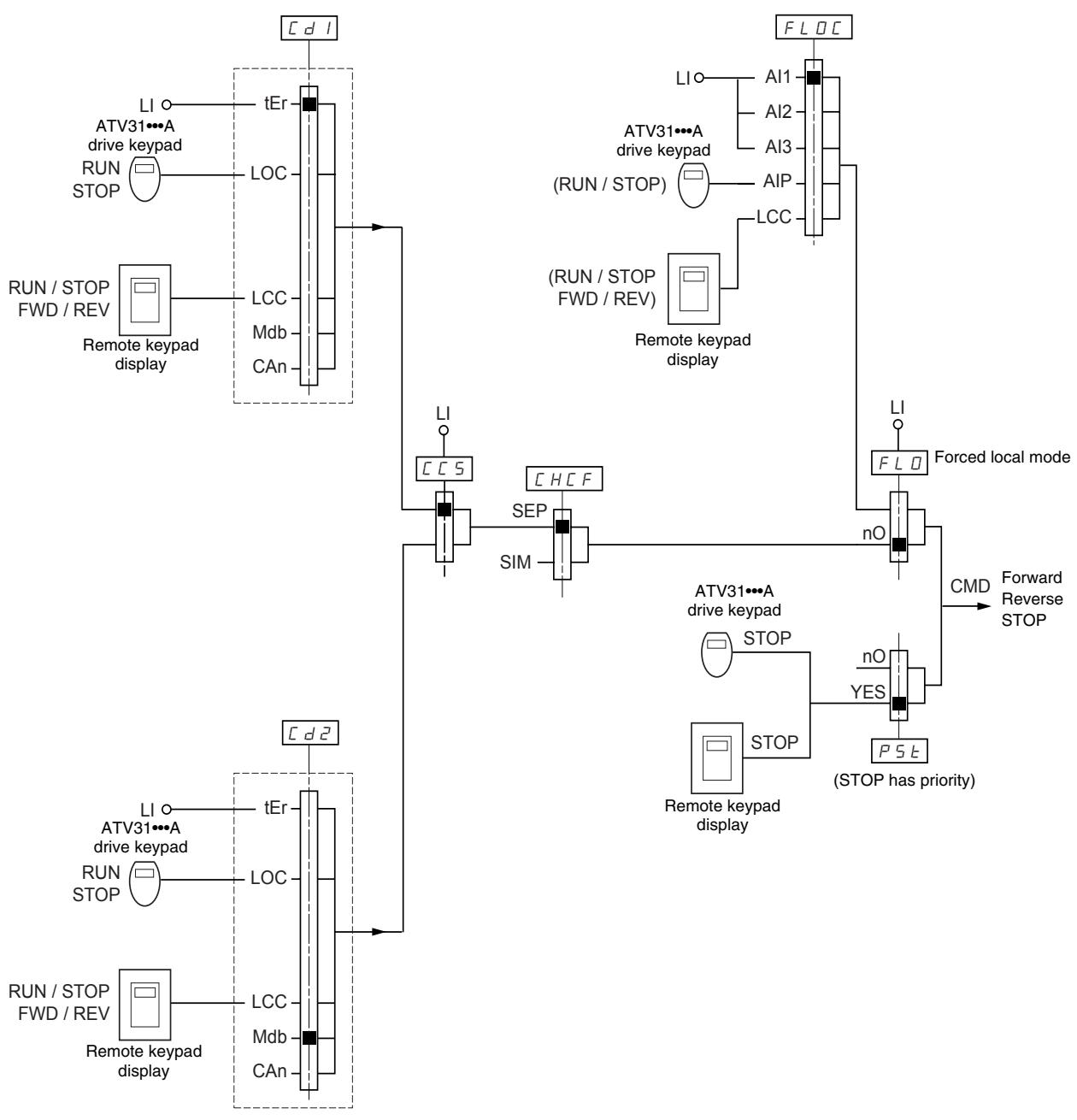
Control Channel for LAC = L3: CHCF = SEP, Mixed Mode (Separate Reference and Control)
Parameters FLO and FLOC are common to reference and control. For example, if the reference in forced local mode is via the analog input on the terminal block, control in forced local mode is via the logic input on the terminal block.
Legend:
Refer to the function compatibility table on page 21. It is not possible to configure incompatible control functions. The first function configured will prevent any functions that are incompatible with it from being configured.

| Code | Description | Adjustment Range | Factory Setting |
| LRC | Function access level | See below. | L1 |
| L: Level 1—access to standard functions.L:2: Level 2—access to the level 1 functions plus the following advanced functions in the FUn- menu:·+/- speed·Brake control·Switching for second current limit·Motor switching·Management of limit switchesL:3: Level 3—access to all of the level 2 functions plus mixed mode operation.Assigning L3 to LAC restores parameters Fr1 (below), Cd1 (page 47), CHCF (page 47), and tCC (page 33) to their factory settings (on ATV31-----A drive controllers, tCC is reset to 2C).If LAC is set to L3, you must restore the factory setting with parameter FCS (page 49) to set LAC back to L1 or to change it to L2.If LAC is set to L2, you must restore the factory setting with parameter FCS to set LAC back to L1.If LAC is set to L2, you can change LAC to L3 without using parameter FCS.NOTE: In order to change the assignment of LAC, you must press and hold down the ENT key for 2 seconds. | |||
| Fr l | Configuration of reference 1 | See below. | Al1AIP for ATV31-----A |
| R l: Analog input Al1R l:2: Analog input Al2R l:3: Analog input Al3R l:P: Potentiometer (ATV31-----A)If LAC = L2 or L3, the following additional assignments are possible:U P d E: + speed/- speed via LI1U P d H: + speed/- speed via ▲▼ on the drive keypad display (ATV31 or ATV31-----A) or on the remote keypad display. For operation, display the frequency rFr (see page 85).1If LAC = L3, the following additional assignments are possible:L C: Reference via the remote keypad display, LFr parameter in the SET- menu page 26.P d b: Reference via ModbusC R n: Reference via CANopen | |||
| F r 2 | Configuration of reference 2 | See below. | nO |
| n D: Not assignedR l:1: Analog input Al1R l:2: Analog input Al2R l:3: Analog input Al3R l:P: Potentiometer (ATV31-----A only)If LAC = L2 or L3, the following additional assignments are possible:U P d E: + speed/- speed via LI1U P d H: + speed/- speed via ▲▼ on the drive keypad display (ATV31 or ATV31-----A) or on the remote keypad display. For operation, display the frequency rFr (see page 85).1If LAC = L3, the following additional assignments are possible:L LC: Reference via the remote keypad display, LFr parameter in the SET- menu page 26.P d b: Reference via ModbusC R n: Reference via CANopen | |||
1 Only one of the UPdt/UPdH assignments is permitted on each reference channel.

| Code | Description | Adjustment Range | Factory Setting |
| r F C | Reference switching | See below. | Fr1 |
| Use parameter rFC to select channel Fr1 or Fr2, or to configure a logic input or a control bit for remote switching of Fr1 or Fr2.F r 1: Reference = Reference 1F r 2: Reference = Reference 2L 1/1: Logic input LI1L 1/2: Logic input LI2L 1/3: Logic input LI3L 1/4: Logic input LI4L 1/5: Logic input LI5L 1/6: Logic input LI6If LAC = L3, the following additional assignments are possible:C 1/1: Bit 11 of the Modbus control wordC 1/2: Bit 12 of the Modbus control wordC 1/3: Bit 13 of the Modbus control wordC 1/4: Bit 14 of the Modbus control wordC 1/5: Bit 15 of the Modbus control wordC 2/1: Bit 11 of the CANopen control wordC 2/2: Bit 12 of the CANopen control wordC 2/3: Bit 13 of the CANopen control wordC 2/4: Bit 14 of the CANopen control wordC 2/5: Bit 15 of the CANopen control wordThe reference can be switched with the drive controller running.Fr1 is active when the logic input or control word bit is in state 0.Fr2 is active when the logic input or control word bit is in state 1. | |||
| CHCF | Mixed mode (separate control and reference channels) | See below. | SIM |
| CHCF can be accessed if LAC = L3.S I /I: Combined control and reference channelsS E P: Separate control and reference channels | |||
| cd1 | Configuration of control channel 1 | See below. | tErLOC forATV31*****A |
| Cd1 can be accessed if CHCF = SEP and LAC = L3.E r: Terminal block controlL D C: Drive keypad display control (ATV31*****A only)L C C: Remote keypad display controlII d b: Control via ModbusC H n: Control via CANopen | |||
| cd2 | Configuration of control channel 2 | See below. | Mdb: |
| Cd2 can be accessed if CHCF = SEP and LAC = L3.E r: Terminal block controlL D C: Drive keypad display control (ATV31*****A only)L C C: Remote keypad display controlII d b: Control via ModbusC H n: Control via CANopen | |||
These parameters only appear if the function has been enabled.
| Code | Description | Adjustment Range | Factory Setting |
| C C S | Control channel switching | See below. | Cd1 |
| CCS can be accessed if CHCF = SEP and LAC = L3. Use parameter CCS to select channel Cd1 or Cd2, or to configure a logic input or a control bit for remote switching of Cd1 or Cd2. | |||
| C d I: Control channel = Channel 1 | |||
| C d 2: Control channel = Channel 2 | |||
| L I I: Logic input LI1 | |||
| L I 2: Logic input LI2 | |||
| L I 3: Logic input LI3 | |||
| L I 4: Logic input LI4 | |||
| L I 5: Logic input LI5 | |||
| L I 6: Logic input LI6 | |||
| C I I I: Bit 11 of the Modbus control word | |||
| C I I 2: Bit 12 of the Modbus control word | |||
| C I I 3: Bit 13 of the Modbus control word | |||
| C I I 4: Bit 14 of the Modbus control word | |||
| C I I 5: Bit 15 of the Modbus control word | |||
| C 2 I I: Bit 11 of the CANopen control word | |||
| C 2 I 2: Bit 12 of the CANopen control word | |||
| C 2 I 3: Bit 13 of the CANopen control word | |||
| C 2 I 4: Bit 14 of the CANopen control word | |||
| C 2 I 5: Bit 15 of the CANopen control word | |||
| Channel 1 is active when the input or control word bit is in state 0. | |||
| Channel 2 is active when the input or control word bit is in state 1. | |||
| C O P | Copy channel 1 to channel 2. (The copy is possible only in this direction.) | See below. | nO |
| COP can be accessed if LAC = L3. | |||
| n D: No copy | |||
| S P: Copy reference | |||
| C d: Copy control | |||
| R L L: Copy control and reference | |||
| If channel 2 is controlled via the terminal block, channel 1 control is not copied. | |||
| If channel 2 reference is set via AI1, AI2, AI3, or AIP, channel 1 reference is not copied. | |||
| The reference copied is FrH (before the ramp) unless the channel 2 reference is set via +/- speed. In this case, the reference copied is rFr (after ramp). | |||
| NOTE: Copying the control and/or the reference may change the direction of rotation. | |||
| L C C | Control via the remote keypad display | See below. | nO |
| LCC can only be accessed if the drive controller is equipped with a remote keypad display, and if LAC = L1 or L2. | |||
| n D: Function inactive | |||
| Y E S: Enables control of the drive controller with the STOP/RESET, RUN, and FWD/REV buttons on the remote keypad display. The speed reference is given by parameter LFr in the SET- menu. Only the freewheel, fast stop, and DC injection stop commands remain active on the terminal block. | |||
| If the remote keypad display is not connected, the drive controller will lock on an SLF fault. | |||
These parameters only appear if the function has been enabled.

| Code | Description | Adjustment Range | Factory Setting |
| P5E | Stop priority | See below. | YES |
| PSt gives priority to the STOP key on the drive keypad display (ATV31-----A only) or on the remote keypad display, regardless of the control channel selected (terminal block or communication bus). If set to nO, the active control channel has priority. If the active control channel is the local or remote keypad display, the stop button retains priority, regardless of the setting of PST. NOTE: To change the assignment of PSt, you must press and hold down the ENT key for 2 secondsnD: Function inactive9 E 5: STOP key priority | |||
| A WARNING | |||
| DISABLED STOP COMMANDDisabling the stop key on the drive keypad display or the remote keypad display will prevent the drive controller from stopping when the stop key is pressed. An external stop command must be installed to stop the motor.Failure to follow this instruction can result in death, serious injury, or equipment damage. | |||
| r0E | Direction of operation | See below. | dFr |
| Direction of operation allowed for the RUN key on the drive keypad display (ATV31-----A only). | |||
| dF r: Forwardd r 5: Reverseb D E: On ATV31----- drive controllers, both directions are authorized; on ATV31-----A controllers, only the forward direction is possible. | |||
| SC S | Saving the configuration1 | See below. | See below. |
| nD: Function inactive5 E r l: Saves the current configuration (but not the result of auto-tuning) to EEPROM. SCS automatically switches to nO as soon as the save is performed. Use this function to keep another configuration in reserve, in addition to the current configuration. The drive controller is factory set with the current configuration and the backup configuration both initialized to the factory configuration.If the remote keypad display is connected to the drive controller, up to four additional settings are available: F I L I , F I L 2,F I L 3, and F I L 4. Use these selections to save up to four configurations in the remote keypad display's EEPROM memory.SCS automatically switches to nO as soon as the save is performed. | |||
| FC S | Return to factory settings/Restore configuration1 | See below. | See below. |
| nD: Function inactiver E C l: Replaces the current configuration with the backup configuration previously saved by SCS (SCS set to Strl). rECI is visible only if the backup configuration has been saved. FCS automatically changes to nO as soon as this action is performed.ln l: Replaces the current configuration with the factory settings. FCS automatically switches to nO as soon as this action is performed.If the remote keypad display is connected to the drive controller, up to four additional selections are available corresponding to backup files loaded in the remote keypad display's EEPROM memory: F I L I , F I L 2 , F I L 3 , and F I L 4 . These selections replace the current configuration with the corresponding backup configuration in the remote keypad display. FCS automatically changes to nO as soon as this action is performed.Note: If nR d briefly appears on the display once the parameter has switched to nO, the configuration transfer is not possible and has not been performed (because the controller ratings are different, for example). If nE r briefly appears on the display once the parameter has switched to nO, a configuration transfer error has occurred and the factory settings must be restored using Inl. In both cases, check the configuration to be transferred before trying again.NOTE: For rECI, Inl, and FIL1 to FIL4 to take effect, you must press and hold down the ENT key for 2 s. | |||
1 SCS and FCS can be accessed in several configuration menus, but their settings affect all menus and parameters as a whole.
APPLICATION FUNCTIONS MENU FUN
Application function parameters can only be modified when the drive controller is stopped and with no run command present. On the remote keypad display, this menu can be accessed with the access locking switch in the position.
Some functions in this menu have numerous parameters. To simplify programming and to minimize scrolling, these functions are grouped into sub-menus. Like menus, sub-menus are identified by a dash. For example, LIA- is a sub-menu, but LIn is a parameter.
It is not possible to configure incompatible application functions. The first function configured will prevent any functions that are incompatible with it from being configured. Refer to the function compatibility table on page 21.

| Sub-menu | Parameter | Description | Adjustment Range | Factory Setting |
| r P C - | Ramp adjustment | |||
| r P E | Ramp type Defines the shape of the acceleration and deceleration ramps. | Lin | ||
| L / n: Linear 5: S ramp U: U ramp C / 5: Customized S ramps f (Hz) HSP f (Hz) 0 t2 t1 t1 t2 t2 t1 U ramps f (Hz) HSP f (Hz) 0 t2 t1 t1 t2 t2 t1 Customized ramps f (Hz) HSP f (Hz) 0 t1 t2 t3 t3 t4 t4 t2 dEC or dE2 | The curve coefficient is fixed, with t2 = 0.6 x t1 with t1 = set ramp time. The curve coefficient is fixed, with t2 = 0.5 x t1 with t1 = set ramp time. tA1: Can be set between 0 and 100% (of ACC or AC2) tA2: Can be set between 0 and (100% - tA1) (of ACC or AC2) tA3: Can be set between 0 and 100% (of dEC or dE2) tA4: Can be set between 0 and (100% - tA3) (of dEC or dE2) | |||
| t R I | Start of CUS-type acceleration ramp rounded as a percentage of total ramp time (ACC or AC2). | 0 to 100% | 10% | |

These parameters only appear if the function has been enabled.

| Sub-menu | Parameter | Description | Adjustment Range | Factory Setting | ||
| rPC- (continued) | t R2 | End of CUS-type acceleration ramp rounded as a percentage of total ramp time (ACC or AC2) | 0 to (100% - tA1) | 10% | ||
| t R3 | Start of CUS-type deceleration ramp rounded as a percentage of total ramp time (dEC or dE2) | 0 to 100% | 10% | |||
| t R4 | End of CUS-type deceleration ramp as a percentage of total ramp time (dEC or dE2) | 0 to (100% - tA3) | 10% | |||
| RCC dEC | Acceleration and deceleration ramp times1 | 0.1 to 999.9 s | 3 s | |||
| Acceleration ramp time for the motor to go from 0 Hz to FrS (parameter in the drC- menu, see page 30).Deceleration ramp time for the motor to go from FrS to 0 Hz. Ensure that the value of dEC is not set too low for the load. | ||||||
| rPS | Ramp switching | See below. | nO | |||
| This function remains active regardless of the control channel.nD: Not assignedL / I: Logic input LI1L / ζ: Logic input LI2L / η: Logic input LI3L / έ: Logic input LI4L / Τ: Logic input LI5L / Υ: Logic input LI6If LAC = L3, the following assignments are possible:C d / I: Bit 11 of the Modbus or CANopen control wordC d / Α: Bit 12 of the Modbus or CANopen control wordC d / : Bit 13 of the Modbus or CANopen control wordC d / Σ: Bit 14 of the Modbus or CANopen control wordC d / Τ: Bit 15 of the Modbus or CANopen control wordACC and dEC are enabled when the logic input or control word bit is in state 0.AC2 and dE2 are enabled when the logic input or control word bit is in state 1. | ||||||
| F r E | Ramp switching threshold | 0 to 500 Hz | 0 | |||
| The second ramp is switched if the value of Frt is not equal to 0 and the output frequency is greater than Frt.Setting Frt to 0 deactivates it.Ramp switching threshold can be combined with switching via a logic input or a control word bit as follows: | ||||||
| LI or bit | Frequency | Ramp | ||||
| 0 | <Frt> | ACC, dEC | ||||
| 0 | >Frt | AC2, dE2 | ||||
| 1 | <Frt> | AC2, dE2 | ||||
| 1 | >Frt | AC2, dE2 | ||||
| RCC2 | 2ndacceleration ramp time1:Enabled via logic input (rPS) or frequency threshold (Frt). | 0.1 to 999.9 s | 5 s | |||
| d E 2 | 2nddeceleration ramp time1:Enabled via logic input (rPS) or frequency threshold (Frt). | 0.1 to 999.9 s | 5 s | |||
| br R | Deceleration ramp adaptation | See below. | YES | |||
| Activating this function automatically adapts the deceleration ramp if it has been set at too low a value for the inertia of the load.nD: Function inactiveY E 5: Function activebrA is incompatible with applications requiring positioning on a ramp or the use of a braking resistor.brA is forced to nO if brake control (bLC) is assigned (page 72). | ||||||
1 Can also be accessed in the Settings menu, SEt- See page 25.

These parameters only appear if the function has been enabled.

| Sub-menu | Parameter | Description | Adjustment Range | Factory Setting |
| 5 E C - | Stop modes | |||
| 5 E E | Normal stop type | See below. | RMP | |
| Type of stop executed when the run command disappears or a stop command appears. | ||||
| r P: Follow rampF 5 E: Fast stopn 5 E: Freewheel stopd C I: DC injection stop | ||||
| F 5 E | Fast stop via logic input | See below. | nO | |
| n D: Not assignedL / I: Logic input LI1L / E: Logic input LI2L / J: Logic input LI3L / A: Logic input LI4L / S: Logic input LI5L / B: Logic input LI6If LAC = L3, the following assignments are possible:C d / I: Bit 11 of the Modbus or CANopen control wordC d / J: Bit 12 of the Modbus or CANopen control wordC d / J: Bit 13 of the Modbus or CANopen control wordC d / A: Bit 14 of the Modbus or CANopen control wordC d / S: Bit 15 of the Modbus or CANopen control wordFast stop is activated when the state of the logic input changes to 0 or the control word bit changes to 1.Fast stop is a stop on the deceleration reduced by the coefficient specified by parameter dCF. If the logic input falls back to state 1 and the run command is still active, the motor will only restart if 2-wire control is configured (tCC = 2C and tCt = LEL or PFO, see page 33). Otherwise, a new run command must be sent. | ||||
| d C F | Coefficient for dividing the deceleration ramp time for fast stopping. | 0, 1 to 10 | 4 | |
| This parameter only appears if FST is assigned. Ensure that the reduced ramp is not too low for the load.The value 0 corresponds to the minimum ramp. | ||||
| d C I | DC injection via logic input | See below. | nO | |
| n D: Not assignedL / I: Logic input LI1L / J: Logic input LI2L / A: Logic input LI3L / A: Logic input LI4L / S: Logic input LI5L / B: Logic input LI6If LAC = L3, the following assignments are possible:C d / I: Bit 11 of the Modbus or CANopen control wordC d / J: Bit 12 of the Modbus or CANopen control wordC d / J: Bit 13 of the Modbus or CANopen control wordC d / A : Bit 14 of the Modbus or CANopen control wordC d / S: Bit 15 of the Modbus or CANopen control wordBraking is activated when the state of the logic input or control word bit is 1. | ||||
| I d C | Level of DC injection braking current activated via logic input or selected as stop mode 1, 2 | 0 to In 3 | 0.7 In 3 | |
| After 5 seconds, the injection current is peak limited at 0.5 lth. | ||||
| I d C | Total DC injection braking time when dCI is selected as the normal stop type (see Stt above).1, 2 | 0.1 to 30 s | 0.5 s | |
1 Can also be accessed in the Settings menu, SEt- See page 25.
2 These settings are not related to the automatic DC injection function.
3 In corresponds to the nominal drive current indicated in the ATV31 Installation Manual and on the drive controller nameplate.
These parameters only appear if the function has been enabled.

| Sub-menu | Parameter | Description | Adjustment Range | Factory Setting |
| 5 E C - (continued) | n 5 E | Freewheel stop via logic input | nO | |
| n D: Not assigned | ||||
| L / I: Logic input LI1 | ||||
| L / 2: Logic input LI2 | ||||
| L / 3: Logic input LI3 | ||||
| L / 4: Logic input LI4 | ||||
| L / 5: Logic input LI5 | ||||
| L / 6: Logic input LI6 | ||||
| Freewheel stop is activated when the logic input is at state 0. If the input returns to state 1 and the run command is still active, the motor will only restart if 2-wire control is configured. Otherwise, a new run command must be sent. | ||||
WARNING
NO HOLDING TORQUE
- DC injection braking does not provide holding torque at zero speed.
- DC injection braking does not function during a loss of power or during a drive controller fault.
- When required, use a separate brake for holding torque.
EXCESSIVE DC INJECTION BRAKING
- Application of DC injection braking for long periods of time can cause motor overheating and damage.
- Protect the motor from extended periods of DC injection braking.
Failure to follow these instructions can result in death, serious injury, or equipment damage.

| Sub-menu | Parameter | Description | Adjustment Range | Factory Setting |
| RdC - | Automatic DC injection. See page 53. | |||
| RdC | Automatic DC injection(at the end of the ramp) | See below. | YES | |
| n D: No injectionE E S: DC injection for an adjustable periodC E: Continuous DC injectionNOTE: If this parameter is set to Yes or Ct, DC current is injected even if a run command has not been sent.The parameter can be accessed with the drive controller running. | ||||
| TdC I | Automatic injection time1 | 0.1 to 30 s | 0.5 s | |
| SdC I | Level of automatic DC injection current1 | 0 to 1.2 In2 | 0.7 In2 | |
| Note: Ensure that the motor will withstand this current without overheating. | ||||
| TdC2 | 2ndautomatic DC injection time1 | 0 to 30 s | 0 s | |
| SdC2 | 2ndlevel of automatic DC injection current1 | 0 to 1.2 In2 | 0.5 In2 | |
| NOTE: Ensure that the motor will withstand this current without overheating. | ||||
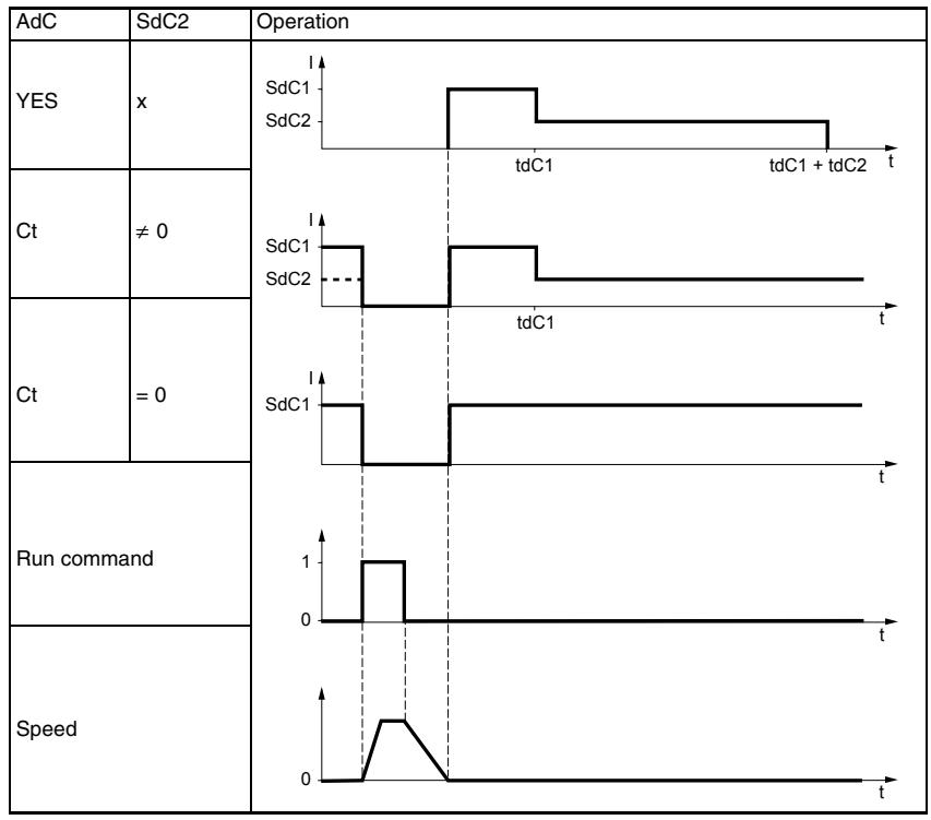
1 Can also be accessed in the Settings menu, SEt-. See page 25.
2 In corresponds to the nominal drive current indicated in the ATV31 Installation Manual and on the drive controller nameplate.

These parameters only appear if the function has been enabled.

| Sub-menu | Parameter | Description | Adjustment Range | Factory Setting |
| 5 R I - | Summing inputsCan be used to sum one or two inputs with reference Fr1. | |||
| 5 R 2 | Summing input 2 | See below. | AI2 | |
| n D: Not assignedR I I: Analog input AI1R I 2: Analog input AI2R I 3: Analog input AI3R I P: Potentiometer (ATV31-----A drive controllers only)If LAC = L3, the following assignments are possible:π d b: Reference via ModbusC R n: Reference via CANopenL C C: Reference via the remote keypad display, LFr parameter in the SEt- menu page 26. | ||||
| 5 R 3 | Summing input 3 | See below. | nO | |
| n D: Not assignedR I I: Analog input AI1R I 2: Analog input AI2R I 3: Analog input AI3R I P: Potentiometer (ATV31-----A drive controllers only)If LAC = L3, the following assignments are possible:π d b: Reference via ModbusC R n: Reference via CANopenL C C: Reference via the remote keypad display (LFr parameter in the SEt- menu. See page 26.) | ||||
Summing Inputs
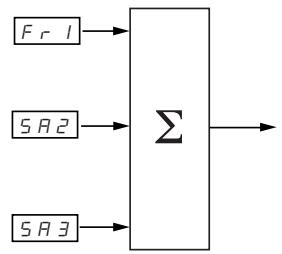
NOTE: AI2 is an input, ± 10V , which can allow a subtraction by summing a negative signal.
Refer to the diagrams on pages 41 and 43.
Preset Speeds
Parameter PSS, preset speeds, allows 2, 4, 8, or 16 preset speeds, requiring 1, 2, 3, or 4 logic inputs respectively.
The preset speeds must be assigned in the following order: PS2, then PS4, then PS8, then PS16.
Refer to the following table for combining inputs to activate the various preset speeds:
| 16 speeds LI (PS16) | 8 speeds LI (PS8) | 4 speeds LI (PS4) | 2 speeds LI (PS2) | Speed reference |
| 0 | 0 | 0 | 0 | Reference1 |
| 0 | 0 | 0 | 1 | SP2 |
| 0 | 0 | 1 | 0 | SP3 |
| 0 | 0 | 1 | 1 | SP4 |
| 0 | 1 | 0 | 0 | SP5 |
| 0 | 1 | 0 | 1 | SP6 |
| 0 | 1 | 1 | 0 | SP7 |
| 0 | 1 | 1 | 1 | SP8 |
| 1 | 0 | 0 | 0 | SP9 |
| 1 | 0 | 0 | 1 | SP10 |
| 1 | 0 | 1 | 0 | SP11 |
| 1 | 0 | 1 | 1 | SP12 |
| 1 | 1 | 0 | 0 | SP13 |
| 1 | 1 | 0 | 1 | SP14 |
| 1 | 1 | 1 | 0 | SP15 |
| 1 | 1 | 1 | 1 | SP16 |
1 See the diagrams on page 41 and page 43: Reference 1 = (SP1).

| Sub-menu | Parameter | Description | Adjustment Range | Factory Setting |
| P 5 5 - | Preset speeds | |||
| P 5 2 | 2 preset speeds | See below. | If tCC = 2C: LI3If tCC = 3C: nOIf tCC = LOC: LI3 | |
| Selecting the assigned logic input activates the function.n D: Not assignedL / I: Logic input LI1L / 2: Logic input LI2L / 3: Logic input LI3L / 4: Logic input LI4L / 5: Logic input LI5L / 6: Logic input LI6If LAC = L3, the following assignments are possible:C d / I: Bit 11 of the Modbus or CANopen control wordC d / 2: Bit 12 of the Modbus or CANopen control wordC d / 3: Bit 13 of the Modbus or CANopen control wordC d / 4: Bit 14 of the Modbus or CANopen control wordC d / 5: Bit 15 of the Modbus or CANopen control word | ||||
| P 5 4 | 4 preset speeds | See below. | If tCC = 2C: LI4If tCC = 3C: nOIf tCC = LOC: LI4 | |
| Selecting the assigned logic input activates the function.NOTE: Ensure that PS2 has been assigned before assigning PS4.n D: Not assignedL / I: Logic input LI1L / 2: Logic input LI2L / 3: Logic input LI3L / 4: Logic input LI4L / 5: Logic input LI5L / 6: Logic input LI6If LAC = L3, the following assignments are possible:C d / I: Bit 11 of the Modbus or CANopen control wordC d / 2: Bit 12 ofthe Modbus or CANopen control wordC d / 3: Bit 13 of the Modbus or CANopen control wordC d / 4: Bit 14 of the Modbus or CANopen control wordC d / 5: Bit 15 of the Modbus or CANopen control word | ||||
| P 5 8 | 8 preset speeds | See below. | nO | |
| Selecting the assigned logic input activates the function.NOTE: Ensure that PS4 has been assigned before assigning PS8.n D: Not assignedL / I: Logic input LI1L / 2: Logic input LI2L / 3: Logic input LI3L / 4: Logic input LI4L / 5: Logic input LI5L / 6: Logic input LI6If LAC = L3, the following assignments are possible:C d / I: Bit 11 of the Modbus or CANopen control wordC d / 2: Bit 12 ofthc Modbus or CANopen control wordC d / 3: Bit 13 of the Modbus or CANopen control wordC d / 4: Bit 14 of the Modbus or CANopen control wordC d / 5: Bit 15 of the Modbus or CANopen control word | ||||

| Sub-menu | Parameter | Description | Adjustment Range | Factory Setting |
| P5/6 | 16 preset speeds | See below. | nO | |
| Selecting the assigned logic input activates the function.NOTE: Ensure that PS8 has been assigned before assigning PS16.n0: Not assignedL1: Logic input LI1L2: Logic input LI2L3: Logic input LI3L4: Logic input LI4L5: Logic input LI5L6: Logic input LI6If LAC = L3, the following assignments are possible:Cd / I: Bit 11 of the Modbus or CANopen control wordCd / 2: Bit 12 of the Modbus or CANopen control wordCd / 3: Bit 13 of the Modbus or CANopen control wordCd / 4: Bit 14 of the Modbus or CANopen control wordCd / 5: Bit 15 of the Modbus or CANopen control word | ||||
| 5P2 | 2ndpreset speed1 | 0.0 to 500.0 Hz | 10 Hz | |
| 5P3 | 3rdpreset speed1 | 0.0 to 500.0 Hz | 15 Hz | |
| 5P4 | 4thpreset speed1 | 0.0 to 500.0 Hz | 20 Hz | |
| 5P5 | 5thpreset speed1 | 0.0 to 500.0 Hz | 25 Hz | |
| 5P6 | 6thpreset speed1 | 0.0 to 500.0 Hz | 30 Hz | |
| 5P7 | 7thpreset speed1 | 0.0 to 500.0 Hz | 35 Hz | |
| 5PB | 8thpreset speed1 | 0.0 to 500.0 Hz | 40 Hz | |
| 5PG | 9thpreset speed1 | 0.0 to 500.0 Hz | 45 Hz | |
| 5P10 | 10thpreset speed1 | 0.0 to 500.0 Hz | 50 Hz | |
| 5P11 | 11thpreset speed1 | 0.0 to 500.0 Hz | 55 Hz | |
| 5P12 | 12thpreset speed1 | 0.0 to 500.0 Hz | 60 Hz | |
| 5P13 | 13thpreset speed1 | 0.0 to 500.0 Hz | 70 Hz | |
| 5P14 | 14thpreset speed1 | 0.0 to 500.0 Hz | 80 Hz | |
| 5P15 | 15thpreset speed1 | 0.0 to 500.0 Hz | 90 Hz | |
| 5P16 | 16thpreset speed1 | 0.0 to 500.0 Hz | 100 Hz | |
1 Can also be accessed in the Settings menu, SEt-. See page 25.

These parameters only appear if the function has been enabled.

| Sub-menu | Parameter | Description | Adjustment Range | Factory Setting | |
| JOG- | Jog operation | ||||
| JOG- | Jog operation | See below. | If tCC = 2C: nO If tCC = 3C: LI4 If tCC = LOC: nO | ||
| Selecting the assigned logic input activates the function. n D: Not assigned L 1: Logic input LI1 L 2: Logic input LI2 L 3: Logic input LI3 L 4: Logic input LI4 L 5: Logic input LI5 L 6: Logic input LI6 Example: 2-wire control operation (tCC = 2C) | |||||
| Motor frequency Reference JGF reference JGF reference LI (JOG) Forward Reverse | Ramp DEC/DE2 Ramp forced to 0.1 s 0 1 0 1 0 | Ramp forced to 0.1 s 0 1 0 1 0 | 1 1 1 1 1 1 1 1 1 1 1 1 1 1 1 1 1 1 1 1 1 1 1 1 1 1 1 1 1 1 1 1 1 1 1 1 1 1 1 1 1 1 1 1 1 1 1 1 1 1 1 | ||
| JGF | Jog operation reference1 | 0 to 10 Hz | 10 Hz | ||
1 Can also be accessed in the Settings menu, SET-. See page 25.
+/- Speed
This function can only be accessed if:
- Parameter LAC is set to L2 or L3 (see page 46).
- Incompatible functions are not active (see page 21).
- Parameter Fr1 or Fr2 is set to UPdt or UPdH.
The following sections describe two types of + / - speed operation: use of single action buttons and use of double action buttons. A pendant station is an example application of both.
Single Action Buttons
Single action buttons require two logic inputs and two directions of rotation. The input assigned to the + speed command increases the speed, the input assigned to the - speed command decreases the speed.
| - speed | speed maintained | + speed | |
| Forward direction | a and d | a | a and b |
| Reverse direction | c and d | c | c and b |
Example of wiring:
LI1: forward
Llx: reverse
Lly: + speed (USP)
Llz: - speed (DSP)

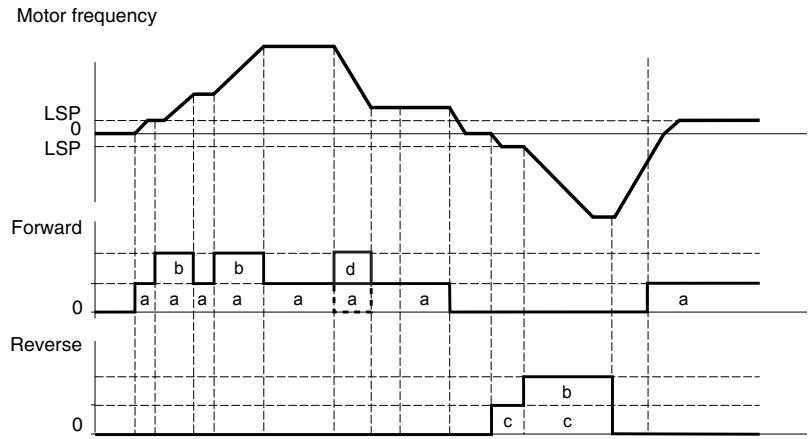
The maximum speed is set by HSP (see page 26).
NOTE: If the reference is switched via rFC (see page 47) from any reference channel to another with +/- speed, the value of reference rFr (after ramp) is copied at the same time. This prevents the speed from being incorrectly reset to zero when switching takes place.
Double Action Buttons
Only one logic input, assigned to + speed, is required for double action buttons. Double action buttons typically have two detents. Press the button to the first detent to maintain speed; press it to the second detent to increase speed. Each action closes a contact. Refer to the following table.
| Released (- speed) | Press to 1stdetent (speed maintained) | Press to 2nddetent (+ speed) | |
| Forward direction | - | a | a and b |
| Reverse direction | - | c | c and d |
Example of wiring:
LI1: forward
Lix: reverse
Lly: + speed (USP)
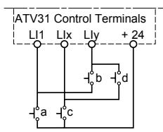
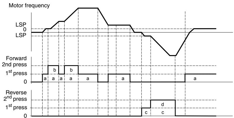
Use of double action buttons is incompatible with 3-wire control.
The maximum speed is set by HSP (see page 26).
NOTE: If the reference is switched via rFC (see page 47) from any reference channel to another with +/- speed, the value of reference rFr (after ramp) is copied at the same time. This prevents the speed from being incorrectly reset to zero when switching takes place.

| Sub-menu | Parameter | Description | Adjustment Range | Factory Setting |
| UPd- | +/- Speed (motorized potentiometer)This function can only be accessed if LAC = L2 or L3 and UPdH or UPdt is active (see page 46). | |||
| U5P | + SpeedCan only be accessed if UPdt is active. | See below. | nO | |
| Selecting the assigned logic input activates the function.n0: Not assignedL / I: Logic input LI1L / 2: Logic input LI2L / 3: Logic input LI3L / 4: Logic input LI4L / 5: Logic input LI5L / 6: Logic input LI6 | ||||
| d5P | - SpeedCan only be accessed if UPdt is active. | See below. | nO | |
| Selecting the assigned logic input activates the function.n0: Not assignedL / I: Logic input LI1L / 2: Logic input LI2L / 3: Logic input LI3L / 4: Logic input LI4L / 5: Logic input LI5L / 6: Logic input LI6 | ||||
| 5E r | Save reference | See below. | nO | |
| Associated with the +/- speed function, this parameter can be used to save the reference:When the run commands are removed, the reference is saved to RAM.When the mains supply or the run commands are removed, the reference is saved to EEPROM.On the next start-up, the speed reference is the last reference saved.n0: No saver RII: Save to RAME E P: Save to EEPROM | ||||

These parameters only appear if the function has been enabled.
PI Regulator
PI regulator provides regulation of a process using feedback from a sensor that sends a signal to the drive controller. This function is often used for pump and fan applications. The PI regulator function is activated by assigning an analog input to PI regulator feedback (PIF).
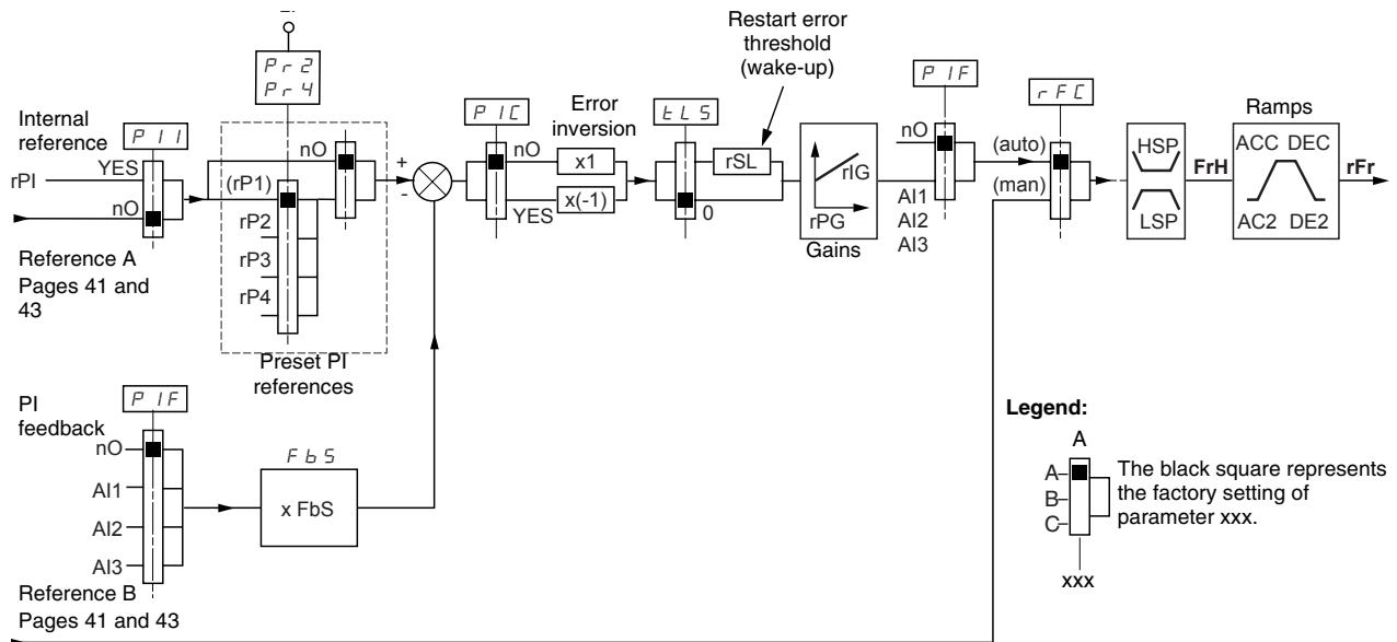
The PI regulator feedback parameter (PIF, see page 68) must be assigned to one of the analog inputs (AI1, AI2, or AI3).
The PI reference can be assigned to the following parameters, in order of priority:
- Preset references via logic inputs (rP2, rP3, and rP4, see page 68)
Internal reference (rPI, see page 69)
Reference Fr1 (see page 46)
Refer to the following table for combining logic inputs for preset PI references.
| LI (Pr4) | LI (Pr2) | Pr2 = nO | Reference |
| rPI or Fr1 | |||
| 0 | 0 | rPI or Fr1 | |
| 0 | 1 | rP2 | |
| 1 | 0 | rP3 | |
| 1 | 1 | rP4 | |
The following parameters can also be accessed in the Settings menu (SEt-, beginning on page 25):
Internal reference (rPI)
- Preset references (rP2, rP3, rP4)
Regulator proportional gain (rPG)
Regulator integral gain (rIG)
PI feedback multiplication coefficient (FbS):
The FbS parameter can be used to scale the reference to the variation range of the PI feedback (sensor range).
For example, Pressure control:
PI reference (process) = 0 to 5 bar = 0 to 100%
Range of pressure sensor = 0 to 10 bar
FbS = Maximum sensor scale / Maximum process
FbS = 10 / 5 = 2
- rSL parameter:
Can be used to set the PI error threshold above which the PI regulator is reactivated (wake-up) after a stop due to the maximum time of operation at low speed being exceeded (tLS).
- Reversal of the direction of correction (PIC):
If PIC = nO , the speed of the motor increases when the error is positive. An example application is pressure control with a compressor.
If PIC = YES, the speed of the motor decreases when the error is positive. An example application is temperature control with a cooling fan.
Manual-Automatic Operation with PI Regulator
Setting up the PI Regulator
This function combines PI regulator and switching of reference rFC (page 47). The speed reference is given by Fr2 or by the PI function, depending on the state of the logic input.
- Configure the drive controller for PI regulator. See the diagram on page 64.
- Perform a test with the factory configuration. In most cases, the factory settings are sufficient. To optimize the drive controller, gradually adjust rPG or rLG independently and observe the effect on PI feedback in relation to the reference.
- If the factory settings are unstable or the reference is incorrect, perform a test with a speed reference in manual mode (without PI regulator) and with the drive controller on load for the speed range of the system:
In steady state, the speed must remain stable at the reference, and the PI feedback signal must be stable.
In transient state, the speed must follow the ramp then stabilize quickly, and the PI feedback must follow the speed.
If this is not the case, check the drive controller settings and the sensor signal and cabling.
- Enable PI regulator.
- Set brA to nO (no auto-adaptation of the ramp).
- Set the speed ramps (ACC, dEC) to the minimum permitted by the application without triggering an ObF fault.
- Set the integral gain (rIG) to the minimum value.
- Observe the PI feedback and the reference.
- Perform several RUN/STOP cycles, or vary the load or reference rapidly.
- Set the proportional gain (rPG) to obtain the ideal compromise between response time and stability in transient phases (slight overshoot and 1 to 2 oscillations before stabilizing).
- If the reference varies from the preset value in steady state, gradually increase the integral gain (rIG) and reduce the proportional gain (rPG) in the event of instability (pump applications) to find a compromise between response time and static precision. Refer to the figure on page 64.
- Perform in-production tests throughout the reference range.
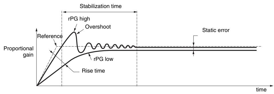
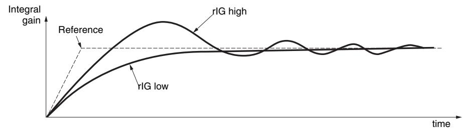
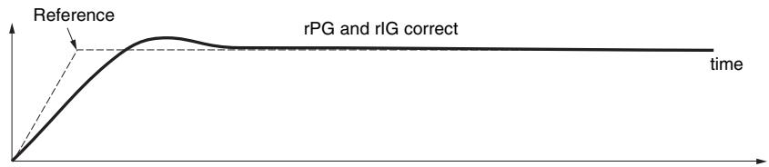
The oscillation frequency depends on the application.
| Parameter | Rise Time | Overshoot | Stabilization Time | Static Error |
| rPG | = | |||
| rIG |

| Sub-menu | Parameter | Description | Adjustment Range | Factory Setting |
| P1- | PI regulator | |||
| PIF | PI regulator feedback | See below. | nO | |
| n0: Not assignedR11: Analog input Al1R12: Analog input Al2R13: Analog input Al3 | ||||
| rPG | PI regulator proportional gain1 | 0.01 to 100 | 1 | |
| Contributes to dynamic performance during rapid changes in the PI feedback. | ||||
| rIG | PI regulator integral gain1 | 0.01 to 100 | 1 | |
| Contributes to static precision during slow changes in the PI feedback. | ||||
| FB5 | PI feedback multiplication coefficient1 | 0.1 to 100 | 1 | |
| For process adaptation | ||||
| PIC | Reversal of the PI regulator direction of correction1 | See below. | nO | |
| n0: normal9 E 5: reverse | ||||
| Pr2 | 2 preset PI references | See below. | nO | |
| Selecting the assigned logic input activates the function.n0: Not assignedL11: Logic input LI1L12: Logic input LI2L13: Logic input LI3L14: Logic input LI4L15: Logic input LI5L16: Logic input LI6If LAC = L3, the following assignments are possible:Cd1: Bit 11 of the Modbus or CANopen control wordCd12: Bit 12 of the Modbus or CANopen control wordCd13: Bit 13 of the Modbus or CANopen control wordCd14: Bit 14 of the Modbus or CANopen control wordCd15: Bit 15 of the Modbus or CANopen control word | ||||
| Pr4 | 4 preset PI references | See below. | nO | |
| Selecting the assigned logic input activates the function.NOTE: Ensure that Pr2 has been assigned before assigning Pr4.n0: Not assignedL11: Logic input LI1L12: Logic input LI2L13: Logic input LI3L14: Logic input LI4L15: Logic input LI5L16: Logic input LI6If LAC = L3, the following assignments are possible:Cd1: Bit 11 of the Modbus or CANopen control wordCd12: Bit 12 of the Modbus or CANopen control wardCd13: Bit 13 of the Modbus or CANopen control wardCd14: Bit 14 of the Modbus or CANopen control wardCd15: Bit 15 of the Modbus or CANopen control ward | ||||
| rP2 | 2ndpreset PI reference1 | 0 to 100% | 30% | |
| Only appears if Pr2 has been enabled by selecting an input. | ||||
| rP3 | 3rdpreset PI reference1 | 0 to 100% | 60% | |
| Only appears if Pr4 has been enabled by selecting an input. | ||||
| rP4 | 4thpreset PI reference1 | 0 to 100% | 90% | |
| Only appears if Pr4 has been enabled by selecting an input. | ||||
1 Can also be accessed in the Settings menu, SEt-. See page 25.
These parameters only appear if the function has been enabled.

| Sub-menu | Parameter | Description | Adjustment Range | Factory Setting |
| P I - (continued) | r S L | Restart after error threshold (wake-up threshold) | 0 to 100% | 0 |
| If the PI and low speed operating time (tLS, see page 28) functions are configured for the same time, the PI regulator may attempt to set a speed lower than LSP. This results in unsatisfactory operation which consists of a cycle of starting, operating at low speed, then stopping. Parameter rSL (restart error threshold) can be used to set a minimum PI error threshold for restarting after a stop at prolonged LSP. The function is inactive if tLS = 0. | ||||
| P I I | Internal PI regulator reference | nO | ||
| n O: The PI regulator reference is Fr1, except for UPdH and UPdt (+/- speed cannot be used as the PI regulator reference). Y E 5: The PI regulator reference is parameter rPI. | ||||
| r P I | Internal PI regulator reference1 | 0 to 100% | 0 | |
1 Can also be accessed in the Settings menu, SEt. See page 25.

These parameters only appear if the function has been enabled.
Brake Control
Brake control enables the drive controller to manage an electromagnetic brake. This function can only be accessed if LAC = L2 or L3 (page 42) and no incompatible functions are programmed (see page 21). It can be assigned to relay R2 or to logic output AOC.
To prevent jolts, synchronize the brake release with torque build-up during startup, and synchronize the brake engage with zero speed on stopping. Refer to the following figure for braking sequence.
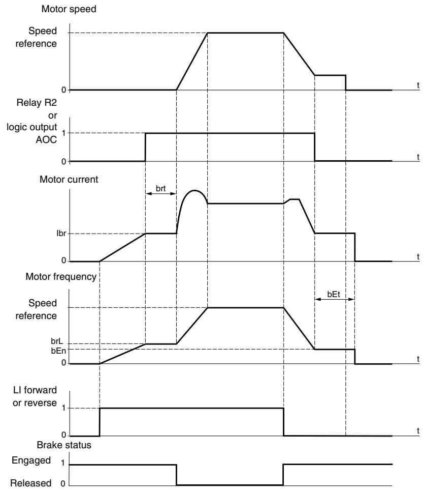
The following parameters can be accessed in the FUn- menu (see page 72):
- Brake release frequency (brL)
- Brake release current (Ibr)
- Brake release time (brt)
- Brake engage frequency (bEn)
- Brake engage time (bEt)
- Brake release pulse (blP)
The following are the recommended settings for brake control:
- Brake release frequency (brL):
Horizontal movement: Set to 0.
Vertical movement: Set to the nominal slip of the motor in Hz.
- Brake release current (Ibr):
Horizontal movement: Set to 0.
Vertical movement: Set to the nominal current of the motor at first, then adjust the release current to prevent jolting on start-up. Ensure that the maximum load is held when the brake is released.
-
Brake release time (brt):
-
Adjust according to the type of brake. Brake release time is the time required for the mechanical brake to release.
-
Brake engage frequency (bEn):
-
Set to twice the nominal slip of the motor, then adjust according to the result.
NOTE: The maximum value of bEn is LSP. Ensure that LSP is set to a sufficient value.
-
Brake engage time (bEt):
-
Adjust according to the type of brake. This is the time required for the mechanical brake to engage.
-
Brake release pulse (bIP):
Horizontal movement: Set to nO.
Vertical movement: Set to YES and ensure that the motor torque direction for forward control corresponds to the upward direction of the load. If necessary, reverse two motor phases. This parameter generates motor torque in an upward direction, regardless of the direction of operation, to maintain the load while the brake is releasing.

| Sub-menu | Parameter | Description | Adjustment Range | Factory Setting |
| bLC- | Brake controlThis function can only be accessed if LAC = L2 or L3 (page 42). | |||
| bLC | Brake control configuration | See below. | nO | |
| nD: Not assignedr2: Relay R2dD: Logic output AOCIf bLC is assigned, parameter FLr (page 80) and brA (page 52) are forced to nO, and parameter OPL (page 80) is forced to YES. | ||||
| brL | Brake release frequency | 0.0 to 10.0 Hz | Varies with drive controller rating | |
| Ibr | Motor current threshold for brake release | 0 to 1.36 In1 | Varies with drive controller rating | |
| brE | Brake release time | 0 to 5 s | 0.5 s | |
| LSP | Low speed | 0 to HSP (page 26) | 0 Hz | |
| Motor frequency at minimum reference. This parameter can also be modified in the SET- menu (page 26). | ||||
| bEn | Brake engage frequency threshold | nO, 0 to LSP Hz | nO | |
| nD: Not setIf bLC is assigned and bEn = nO, the drive controller will trip on bLF fault at start-up. | ||||
| bEt | Brake engage time | 0 to 5 s | 0.5s | |
| bIP | Brake release pulse | See below. | nO | |
| nD: While the brake is releasing, the motor torque direction corresponds to the commanded direction of rotation.YE 5: While the brake is releasing, the motor torque direction is always forward, regardless of the commanded direction of rotation.Ensure that the motor torque direction for Forward control corresponds to the upward direction of the load. If necessary, reverse two motor phases. | ||||
1 In corresponds to the nominal drive current indicated in the ATV31 Installation Manual and on the drive controller nameplate.

These parameters only appear if the function has been enabled.

| Sub-menu | Parameter | Description | Adjustment Range | Factory Setting |
| L C 2 - | Switching for second current limitThis function can only be accessed if LAC = L2 or L3 (page 42). | |||
| L C 2 | Switching for second current limit | See below. | nO | |
| Selecting the assigned logic input activates the function.n D: Not assignedL I I: Logic input LI1L I 2: Logic input LI2L I 3: Logic input LI3L I 4: Logic input LI4L I 5: Logic input LI5L I 6: Logic input LI6If LAC = L3, the following assignments are possible:C d I I: Bit 11 of the Modbus or CANopen control wordC d I 2: Bit 12 of the Modbus or CANopen control wordC d I 3: Bit 13 of the Modbus or CANopen control wordC d I 4: Bit 14 of the Modbus or CANopen control wordC d I 5: Bit 15 of the Modbus or CANopen control wordCL1 is enabled when the logic input or control word bit is in state 0 (SEt- menu page 28).CL2 is enabled when the logic input or control word bit is in state 1. | ||||
| L C 2 | 2ndcurrent limit1 | 0.25 to 1.5 In2 | 1.5 In2 | |
1 Can also be accessed in the Settings menu, SEt-. See page 25.
2 In corresponds to the nominal drive current indicated in the ATV31 Installation Manual and on the drive controller nameplate.

These parameters only appear if the function has been enabled.

| Sub-menu | Parameter | Description | Adjustment Range | Factory Setting |
| C HP - | Motor switchingThis function can only be accessed if LAC = L2 or L3 (page 42). | |||
| C HP | Switching, motor 2 | See below. | nO | |
| n D: Not assignedL / I: Logic input LI1L / 2: Logic input LI2L / 3: Logic input LI3L / 4: Logic input LI4L / 5: Logic input LI5L / 6: Logic input LI6If LAC = L3, the following assignments are possible:C d / l: Bit 11 of the Modbus or CANopen control wordC d / 2: Bit 12 of the Modbus or CANopen control wordC d / 3: Bit 13 of the Modbus or CANopen control wordC d / 4: Bit 14 of the Modbus or CANopen control wordC d / 5: Bit 15 of the Modbus or CANopen control wordLI or bit = 0: Motor 1LI or bit = 1: Motor 2The motor switching function disables motor thermal protection. An external means of motor thermal protection must be provided. See the caution message on page 14.If you use this function, do not use the tUn auto-tuning function (page 31) on motor 2 and do not configure tUn to rUn or POn.Changes to parameters do not take effect until the drive controller is stopped. | ||||
| U n 5 Z | Nominal motor voltage (motor 2) given on the nameplate | Varies with drive controller rating | Varies with drive controller rating | |
| ATV31***M2: 100 to 240 VATV31***M3X: 100 to 240 VATV31***N4: 100 to 500 VATV31***S6X:100 to 600 V | ||||
| F r 5 Z | Nominal motor frequency (motor 2) given on the nameplate | 10 to 500 Hz | 50 Hz | |
| The ratio UnS (in V)FrS (in Hz) must not exceed the following valuesATV31***M2: 7 max.ATV31***M3X: 7 maxATV31***N4: 14 max.ATV31***S6X: 17 max.Changing the setting of bFr to 60 Hz also changes the setting of FrS2 to 60 Hz. | ||||
| n C r 2 | Nominal motor current (motor 2) given on the nameplate | 0.25 to 1.5 In 1 | Varies with drive controller rating | |
| n S P Z | Nominal motor speed (motor 2) given on the nameplate | 0 to 32760 RPM | Varies with drive controller rating | |
| 0 to 9999 rpm, then 10.00 to 32.76 krpmIf the nameplate indicates synchronous speed and slip (in Hz or as a percentage) instead of nominal speed, calculate nominal speed as follows:Nominal speed = Synchronous speed x 100 - slip as a%orNominal speed = Synchronous speed x 50 - slip in HzorNominal speed = Synchronous speed x 60 - slip in Hz60 - slip in Hz60 - slip in Hz | 100 - slip as a%100or(50 Hz motors)or(60 Hz motors) | |||
1 In corresponds to the nominal drive current indicated in the ATV31 Installation Manual and on the drive controller nameplate.

These parameters only appear if the function has been enabled.

| Sub-menu | Parameter | Description | Adjustment Range | Factory Setting |
| CHP- (continued) | COS2 | Motor power factor (motor 2) given on the nameplate | 0.5 to 1 | Varies with drive controller rating |
| UFB2 | Selection of the type of voltage/frequency ratio (motor 2) | See below. | n | |
| L: Constant torque (for motors connected in parallel or special motors) P: Variable torque (pump and fan applications) n: Sensorless flux vector control (for constant torque applications) n L d: Energy savings (for variable torque applications not requiring high dynamics. This behaves in a similar way to the P ratio at no load and the n ratio at load).VoltageUnSFrS Frequency | ||||
| UFR2 | IR compensation/Voltage boost (motor 2)1 | 0 to 100% | 20 | |
| For UFT2 = n or nLd: IR compensation. For UFT2 = L or P: Voltage boost. Used to optimize the torque at low speed. Increase UFr2 if the torque is insufficient. To avoid operating instability, ensure that the value of UFr2 is not too high for a warm motor. Modifying UFT2 causes UFr2 to return to the factory setting (20%). | ||||
| FLG2 | Frequency loop gain (motor 2)1 | 1 to 100% | 20 | |
| FLG2 can only be accessed if UFT2 = n or nLd (see page 75).This parameter adjusts the speed ramp based on the inertia of the driven load. If the value is too low, the response time is longer. If the value is too high, overspeed or operating instability can result. FLG2 low In this case, increase FLG2 -10 0.1 0.2 0.3 0.4 0.5 t -10 0.1 0.2 0.3 0.4 0.5 t -10 0.1 0.2 0.3 0.4 0.5 t -10 0.1 0.2 0.3 0.4 0.5 t -10 0.1 0.2 0.3 0.4 0.5t -10 0.1 0.2 0.3 0.4 0.5 t -10 0.1 0.2 0.3 0.4 0.5 t -10 0.1 0.2 0.3 0.4 0.5 t -10 0.1 0.2 0.3 0.4 0.5 | ||||
| SETR2 | Frequency loop stability (motor 2)1 | 1 to 100% | 20 | |
| StA2 can only be accessed if UFT2 = n or nLd (see page 75). This parameter adapts the return to steady state after a speed transient (acceleration or deceleration) according to the dynamics of the driven machine. Gradually increase the stability to avoid any overspeed. If the value is too low, overspeed or operating instability can result. If the value is too high, the response time is longer. StA2 low In this case, increase StA2 -10 0.1 0.2 0.3 0.4 0.5 t -10 0.1 0.2 0.3 0.4 0.5 t -10 0.1 0.2 0.3 0.4 0.5 t -10 0.1 0.2 0.3 0.4 0.6 t -10 0.1 0.2 0.3 0.4 0.5 t -10 0.1 0.2 0.3 0.4 0.5 t -10 0.1 0.2 0.3 0.4 0.5 t -10 0.1 0.2 0.3 0.4 0.6 | ||||
| SLP2 | Slip compensation (motor 2)1 | 0 to 150% | 100 | |
| SLP2 can only be accessed if UFT2 = n or nLd (see page 75). This parameter adjusts the slip compensation value fixed by nominal motor speed. If the slip setting < actual slip, the motor is not rotating at the correct speed in steady state. If the slip setting > actual slip, the motor is overcompensated and the speed is unstable. | ||||
Can also be accessed in the Settings menu, SEt-. See page 25.

These parameters only appear if the function has been enabled.
Management of Limit Switches
This function can be used to manage the operation of one or two limit switches, in 1 or 2 directions of operation. It can only be accessed if LAC = L2 or L3 (see page 42). To use the function:
- Assign one or two logic inputs to forward limit and reverse limit.
- Select the type of stop (on ramp, fast, or freewheel stop). After a stop, the motor is permitted to restart in the opposite direction only.
- The stop is performed when the input is in state 0. The direction of operation is authorized in state 1.

| Sub-menu | Parameter | Description | Adjustment Range | Factory Setting |
| L 5 E - | Management of limit switchesLSt- can only be accessed if LAC = L2 or L3 (page 42). | |||
| L R F | Limit, forward direction | See below. | nO | |
| n O: Not assignedL / I: Logic input LI1L / 2: Logic input LI2L / 3: Logic input LI3L / 4: Logic input LI4L / 5: Logic input LI5L / 6: Logic input LI6 | ||||
| L R r | Limit, reverse direction | See below. | nO | |
| n O: Not assignedL / I: Logic input LI1L / 2: Logic input LI2L / 3: Logic input LI3L / 4: Logic input LI4L / 5: Logic input LI5L / 6: Logic input LI6 | ||||
| L R S | Type of limit switch stop | See below. | nSt | |
| r P: On rampF 5 E: Fast stopn 5 E: Freewheel stop | ||||

These parameters only appear if the function has been enabled.

| Sub-menu | Parameter | Description | Adjustment Range | Factory Setting |
| SCS | Saving the configuration1 | See below. | nO | |
| nD: Function inactive5 E r 1: Saves the current configuration (but not the result of auto-tuning) to EEPROM. SCS automatically switches to nO as soon as the save is performed. Use this function to keep another configuration in reserve, in addition to the current configuration.The drive controller is factory set with the current configuration and the backup configuration both initialized to the factory configuration.If the remote keypad display is connected to the drive controller, up to four additional settings are available:F I L 1, F I L 2, F I L 3, and F I L 4. Use these selections to save up to four configurations in the remote keypad display's EEPROM memory.SCS automatically switches to nO as soon as the save is performed. | ||||
| FCS | Return to factory setting/restore configuration1 | See below. | nO | |
| nD: Function inactiver EC l: Replaces the current configuration with the backup configuration previously saved by SCS (SCS set to Strl). rECI is visible only if the backup configuration has been saved. FCS automatically changes to nO as soon as this action is performed.I n l: Replaces the current configuration with the factory settings. FCS automatically switches to nO as soon as this action is performed.If the remote keypad display is connected to the drive controller, up to four additional selections are available corresponding to backup files loaded in the remote keypad display's EEPROM memory:F I L 1, F I L 2,F I L 3, and F I L 4. These selections replace the current configuration with the corresponding backup configuration in the remote keypad display. FCS automatically changes to nO as soon as this action is performed.Note: If n R d briefly appears on the display once the parameter has switched to nO, the configuration transfer is not possible and has not been performed (because the controller ratings are different, for example). If n E r briefly appears on the display once the parameter has switched to nO, a configuration transfer error has occurred and the factory settings must be restored using Inl. In both cases, check the configuration to be transferred before trying again.NOTE: For rECI, Inl, and FIL1 to FIL4 to take effect, you must press and hold down the ENT key for 2 s. | ||||
1 SCS and FCS can be accessed via several configuration menus but they concern all menus and parameters as a whole.
FAULT MENU FLT
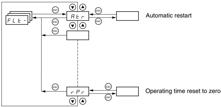
Fault Menu parameters can only be modified when the drive is stopped and no run command is present.
On the optional remote keypad display, this menu can be accessed with the switch in the position.

| Code | Description | Factory Setting |
| R E r | Automatic restart | nO |
| n O: Function inactive | ||
| 9 E 5: Automatic restart after locking on a fault, if the cause of the fault is not longer present and the other operating conditions permit the restart. The restart is performed by a series of automatic attempts separated by increasingly longer waiting periods: 1 s, 5 s, 10 s, then once per minute for the period defined by tAr. If the restart has not taken place once the maximum duration of restart time, tAr, has elapsed, the procedure is aborted and the drive controller remains locked until power is cycled. The following faults permit automatic restart: | ||
| External fault (EPF) | ||
| Loss of 4-20 mA reference (LFF) | ||
| CANopen fault (COF) | ||
| System overvoltage (OSF) | ||
| Loss of a line phase (PHF) | ||
| Loss of a motor phase (OPF) | ||
| DC bus overvoltage (ObF) | ||
| Motor overload (OLF) | ||
| Serial link (SLF) | ||
| Drive overheating (OHF) | ||
| This function requires 2-wire control (tCC = 2C) with tCt = LEL or PFO (page 33). Ensure that an automatic restart will not endanger personnel or equipment in any way. Refer to the Warning message below. | ||
| E R r | Maximum duration of restart process | 5 minutes |
| 5: 5 minutes | ||
| I O: 10 minutes | ||
| 3 O: 30 minutes | ||
| I h: 1 hour | ||
| 2 h: 2 hours | ||
| 3 h: 3 hours | ||
| C E: Unlimited | ||
| This parameter appears if Atr = YES. It can be used to limit the number of consecutive restarts on a recurrent fault. | ||
| r S F | Reset fault | no |
| n O: Not assigned | ||
| L I I: Logic input LI1 | ||
| L I2: Logic input LI2 | ||
| L I3: Logic input LI3 | ||
| L I4: Logic input LI4 | ||
| L I5: Logic input LI5 | ||
| L I6: Logic input LI6 | ||
These parameters only appear if the function has been enabled.
WARNING
- Automatic Restart can only be used for machines or installations that present no danger in the event of automatic restarting, either for personnel or equipment.
- If Automatic Restart is active, R1 will only indicate a fault after the restart sequence has timed out.
- Equipment operation must conform to national and local safety regulations.
Failure to follow these instructions can result in death, serious injury, or equipment damage.

| Code | Description | Factory Setting |
| FL r | Catch on the fly (automatically catch a spinning load on ramp) | nO |
| Enables a smooth restart of a spinning load if the run command is maintained after the following events: • Loss of line supply or disconnection • Fault reset or automatic restart. See the warning on page 79. • Freewheel stop The speed given by the drive controller resumes from the estimated speed of the motor at the time of the restart, then follows the ramp to the reference speed. This function requires 2-wire control (tCC = 2C) with tCt = LEL or PFO. nD: Function inactive yE 5: Function active When the function is enabled, it activates at each run command, resulting in a slight delay (1 second maximum) before start. FLr is forced to nO if brake control (bLC) is assigned (page 72). | ||
| E E F | External fault | nO |
| nD: Not assigned L l l: Logic input LI1 L l 2: Logic input LI2 L l 3: Logic input LI3 L l 4: Logic input LI4 L l 5: Logic input LI5 L l 6: Logic input LI6 If LAC = L3, the following assignments are possible: C d l l: Bit 11 of the Modbus or CANopen control word C d l 2: Bit 12 of the Modbus or CANopen control word C d l 3: Bit 13 of the Modbus or CANopen control word C d l 4: Bit 14 of the Modbus or CANopen control word C d l 5: Bit 15 of the Modbus or CANopen control word | ||
| E P L | Stop mode in the event of an external fault (EtF) | YES |
| nD: Fault ignored yE 5: Fault with a freewheel stop r nP: Fault with a stop on the ramp F 5 E: Fault with a fast stop | ||
| D P L | Configuration of motor phase loss fault | YES |
| nD: Function inactive yE 5: Triggering of OPF fault D R C: No fault is triggered, but output voltage is monitored to avoid an overcurrent when the link with the motor is re-established and a catch on the fly occurs, even if FLr = nO. To be used with a downstream contactor. OPL is forced to YES if brake control (bLC) is assigned (page 72). | ||
| I P L | Configuration of line phase loss fault | YES |
| This parameter is only accessible on three-phase drives. nD: Fault ignored yE 5: Fault with fast stop | ||
| D H L | Stop mode in the event of a drive overheating fault (OHF) | YES |
| nD: Fault ignored yE 5: Fault with a freewheel stop r nP: Fault with a stop on the ramp F 5 E: Fault with a fast stop | ||
| D L L | Stop mode in the event of a motor overload fault (OLF) | YES |
| nD: Fault ignored yE 5: Fault with a freewheel stop r nP: Fault with a stop on the ramp F 5 E: Fault with a fast stop | ||

| Code | Description | Adjustment Range | Factory Setting |
| 5 L L | Stop mode in the event of a Modbus serial link fault (SLF) | See below. | YES |
| n D: Fault ignored y E 5: Fault with a freewheel stop r P: Fault with a stop on the ramp F S E: Fault with a fast stop | |||
| C O L | Stop mode in the event of a CANopen serial link fault (COF) | See below. | YES |
| n D: Fault ignored y E 5: Fault with a freewheel stop r P: Fault with a stop on the ramp F S E: Fault with a fast stop | |||
| E n L | Configuration of auto-tuning fault (tnF) | See below. | YES |
| n D: Fault ignored (the drive controller reverts to the factory settings) y E 5: Fault with drive controller locked | |||
| L F L | Stop mode in the event of a loss of 4 - 20 mA signal fault (LFF) | See below. | nO |
| n D: Fault ignored (only value possible if CrL3 ≤3 mA, see page 34) y E 5: Fault with a freewheel stop L F F: The drive controller switches to the fallback speed (see LFF parameter below) r L 5: The drive controller maintains the speed at which it was running when the fault occurred until the fault is no longer present. r P: Fault with a stop on the ramp F S E: Fault with a fast stop Before setting LFL to YES, rMP, or FSt, check the connection of input Al3. Otherwise, the drive controller may immediately switch to an LFF fault. | |||
| L F F | Fallback speed | 0 to 500 Hz | 10 Hz |
| Fallback speed setting for stopping in the event of a fault | |||
| d r n | Derated operation in the event of an undervoltage | See below. | nO |
| n D: Function inactive y E 5: The line voltage monitoring threshold is: ATV31***M2: 130 V ATV31***M3X: 130 V ATV31***N4: 270 V ATV31***S6X: 340 V In this case, a line choke must be used and the performance of the drive controller cannot be guaranteed. In order to assign this function, you must press and hold down the ENT key for 2 seconds. | |||
| S E P | Controlled stop on loss of mains power | See below. | nO |
| n D: Lock the drive controller and stop the motor on a freewheel n D: Use the inertia to maintain the drive controller power supply as long as possible r P: Stop on the active ramp (dEC or dE2) F S E: Fast stop. The stopping time depends on the inertia and the braking ability of the drive controller. | |||
| l n H | Fault inhibit | See below. | nO |
| CAUTION | |||
| LOSS OF FAULT PROTECTION Inhibiting faults may damage the drive controller beyond repair by preventing shutdown upon occurrence of a fault. Failure to follow this precaution can result in equipment damage. | |||
| n D: Not assigned L I : Logic input LI1 L I 2: Logic input LI2 L I 3: Logic input LI3 L I 4: Logic input LI4 L I 5: Logic input LI5 L I 6: Logic input LI6 Fault monitoring is active when the input is in state 0. It is inactive when the input is in state 1. All active faults are reset when the input state changes from 1 to 0. NOTE: To assign this function, you must press and hold down the ENT key for 2 seconds. | |||
| r P r | Operating time reset to zero | See below. | nO |
| n D: No r E H: Operating time reset to zero The rPr parameter is automatically set to nO as soon as the reset to zero is performed. | |||
COMMUNICATION MENU COM
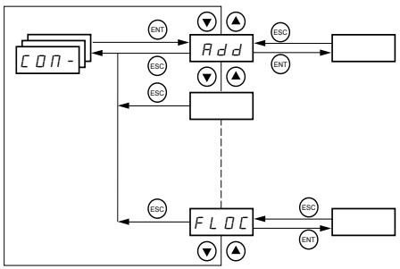
The Communication menu parameters can only be modified when the drive controller is stopped and no run command is present. Modifications to parameters Add, tbr, tFO, AdCO, and bdCO take effect only after a restart.
On the optional remote keypad display, this menu can be accessed with the switch in the position.

| Code | Description | Adjustment Range | Factory Setting |
| Rdd | Modbus: Drive address | 1 to 247 | 1 |
| Ebr | Modbus: Transmission speed | 19200 bps | |
| 4. B: 4800 bps9. B: 9600 bps19. 2: 19200 bpsNOTE: The remote keypad display can only be used with the transmission speed set to 19200 bps. | |||
| ETD | Modbus communication format | See below. | 8E1 |
| B D I: 8 data bits, odd parity, 1 stop bitB E I: 8 data bits, even parity, 1 stop bitB n I: 8 data bits, no parity, 1 stop bitB n 2: 8 data bits, no parity, 2 stop bitsNOTE: The remote keypad display can only be used with the communication format set to 8 data bits, even parity, 1 stop bit. | |||
| ETD | Modbus: Time-out | 0.1 to 10 s | 10 s |
| Rd C D | CANopen: Drive address | 0 to 127 | 0 |
| bd C D | CANopen: Transmission speed | See below. | 125 |
| I D. D: 10 kbps2 D. D: 20 kbps5 D. D: 50 kbpsI 2 D. D: 125 kbps25 D. D: 250 kbps5 D. D: 500 kbpsI D. D: 1000 kbps | |||
| Er C D | CANopen: Error registry (read-only) | See below. | |
| D: No errorI: Bus off error2: Life time error3: CAN overrun4: Heartbeat error | |||
| FL D | Forced local mode | See below. | nO |
| n D: Not assignedL I I: Logic input LI1L I 2: Logic input LI2L I 3: Logic input LI3L I 4: Logic input LI4L I 5: Logic input LI5L I 6: Logic input LI6In forced local mode, the terminal block and drive keypad display regain control of the drive controller. | |||

| Code | Description | Adjustment Range | Factory Setting |
| FLDC | Selection of the reference and control channel in forced local mode Can only be accessed if LAC = 3 | See below. | Al1 AlP for ATV31*****A |
| In forced local mode, only the speed reference is taken into account. PI functions, summing inputs, etc. are not active. Refer to the diagrams on pages 42 to 45. R / I: Analog input AI1, logic inputs LI R / 2: Analog input AI2, logic inputs LI R / 3: Analog input AI3, logic inputs LI R / P: Potentiometer (ATV31*****A controllers only), RUN/STOP buttons L C C: Remote keypad display: LFr reference (page 26), RUN/STOP/FWD/REV buttons | |||

These parameters only appear if the function has been enabled.
DISPLAY MENU SUP
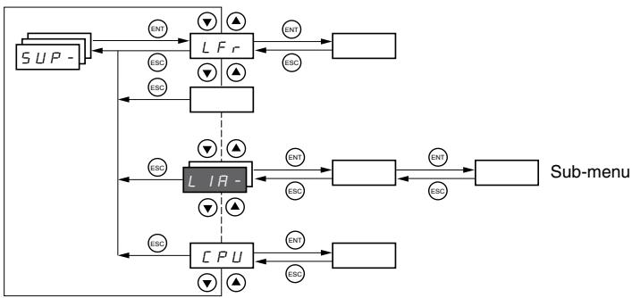
The display menu parameters can be accessed with the drive controller running or stopped. This menu can be accessed with the access locking switch on the remote keypad display in any position.
Some functions have numerous parameters. To simplify programming and to keep parameter lists short, these functions have been grouped in sub-menus. Like menus, sub-menus are identified by a dash after their code. For example, LIA- is a submenu.
When the drive controller is running, the value of one of the display parameters is shown. To change the parameter displayed, scroll to the desired display parameter and press the ENT key. To retain your selection as the new default, press and hold the ENT key again for 2 seconds. The value of this parameter will be displayed during operation, even after power to the drive controller has been cycled. If the new choice is not confirmed by pressing the ENT key a second time, the drive controller will return to the previous parameter after power is cycled.

| Code | Description | Adjustment Range |
| L F r | Frequency reference for control via the drive controller keypad or the remote keypad display | 0 to 500 Hz |
| r P l | Internal PI reference | 0 to 100% |
| F r H | Frequency reference before ramp (absolute value) | 0 to 500 Hz |
| r F r | Output frequency applied to the motor | -500 Hz to +500 Hz |
| SP d l o r SP d 2 o r SP d 3 | Output value in customer unitsSPd1, SPd2, or SPd3 depending on the SdS parameter, see page 29. Factory setting is SPd3. | |
| L C r | Motor current | |
| O P r | Motor power | |
| 100% = Nominal motor power, calculated using the parameters entered in the drC- menu. | ||
| U L n | Line voltage (Vac) calculated from the measured voltage on the DC bus | |
| E H r | Motor thermal state | |
| 100% = Nominal thermal state118% = OLF threshold (motor overload) | ||
| E H d | Drive thermal state | |
| 100% = Nominal thermal state118% = OHF threshold (drive overheating) | ||
| L F e | Last fault | |
| b L F: Brake control faultC F F: Configuration (parameters) incorrectC F I: Configuration (parameters) invalidC D F: Communication fault line 2 (CANopen)C r F: Capacitor pre-charge faultE E F: EEPROM memory faultE P F: External faultI n F: Internal faultL F F: 4 - 20 mA fault on Al3n D F: No fault savedB b F: DC bus overvoltage faultC F: Overcurrent faultH F: Drive overheating faultL F: Motor overload faultP F: Motor phase loss faultS F: Line supply overvoltage faultPH F: Line supply phase loss faultS F: Motor short-circuit fault (phase, earth)S L F: Modbus communication faultS D F: Motor overspeed faultE n F: Auto-tuning faultU S F: Line supply undervoltage fault | ||
| O E r | Motor torque | |
| 100% = Nominal motor torque, calculated using the parameters entered in the drC- menu. | ||
| r E H | Operating time | 0 to 65530 hours |
| Total time the motor has been powered up:0 to 9999 (hours), then 10.00 to 65.53 (khours).Can be reset to zero by the rPr parameter in the FLt- menu (see page 81). | ||

These parameters only appear if the function has been enabled.

| Code | Description | |
| C d | Terminal locking code | |
| Allows the drive configuration to be protected with an access locking code. | ||
| NOTE: Before entering a code, be sure to record it. | ||
| ☐ F F: No access locking code | ||
| • To lock the access, use the▲ key to enter a code (2 to 9999) and press ENT. "ON" appears on the screen to indicate that the parameters have been locked. | ||
| ☐ n: A code (2 to 9999) is locking the access to the drive controller | ||
| • To unlock the access, use the▲ key to enter the access code (2 to 9999) and press ENT. The code remains on the display and the access is unlocked until the next time the power is removed from the controller. Parameter access will be locked again the next time power is reapplied. | ||
| • If an incorrect code is entered, the display changes to "ON" and the parameters remain locked. | ||
| XXXX: Parameter access is unlocked (the code remains on the screen). | ||
| • To reactivate locking with the same code when the parameters have been unlocked, return to ON. using the▼ button then press ENT. "ON" appears on the screen to indicate that the parameters have been locked. | ||
| • To lock the access with a new code when the parameters have been unlocked, enter a new code (increment the display using▲ or▼) and press ENT. "ON" appears on the screen to indicate that the parameters have been locked. | ||
| • To clear locking when the parameters have been unlocked, return to OFF using the▼ button and press ENT. "OFF" remains on the screen. The parameters are unlocked and will remain unlocked. | ||
| When the access is locked using a code, only the display parameters are accessible, with only a temporary choice of the parameter displayed. | ||
| L US | Auto-tuning status. See page 31. | |
| E R b: The default stator resistance value is used to control the motor. | ||
| P E n d: Auto-tuning has been requested, but not yet performed. | ||
| P r ☐ G: Auto-tuning in progress. | ||
| F R I L: Auto-tuning has failed. | ||
| d ☐ n E: Auto-tuning is complete. The stator resistance measured by the auto-tuning function is used to control the motor. | ||
| S E r d: Auto-tuning is complete. The cold stator resistance (rSC other than nO) is used to control the motor. | ||
| U d P | Indicates the ATV31 firmware version. | |
| For example, 1102 = V1.1 IE02. | ||
| L I R - | Logic input functions | |
| L I I R | Can be used to display the functions assigned to each input. If no functions are assigned, nO is displayed. | |
| L I 2 R | Use ▲ and ▼ to scroll through the functions. If a number of functions have been assigned to the same input, ensure that they are compatible. | |
| L I 3 R | ||
| L I 4 R | ||
| L I 5 R | ||
| L I 6 R | ||
| L I 5 | Can be used to display the state of the logic inputs (using the segments of the display: high = 1, low = 0) | |
| State 1 | ||
| State 0 | ||
| LI1 LI2 LI3 LI4 LI5 LI6 | ||
| Example above: LI1 and LI6 are at 1, LI2-LI5 are at 0. | ||
| R I R - | Analog input functions | |
| R I I R | Can be used to display the functions assigned to each input. If no functions have been assigned, nO is displayed. Use ▲ and ▼ to scroll through the functions. If a number of functions are assigned to the same input, ensure that they are compatible. | |
| R I 2 R | ||
| R I 3 R | ||
SECTION 4: MAINTENANCE AND TROUBLESHOOTING
PRECAUTIONS
Read the following safety statements before proceeding with any maintenance or troubleshooting procedures.
DANGER
HAZARDOUS VOLTAGE
- Disconnect all power before servicing the drive controller.
- Read and understand these procedure and the precaution on page 16 of this manual before servicing the ATV31 drive controllers.
- Installation, adjustment, and maintenance of these drive controllers must be performed by qualified personnel.
Failure to follow this instruction will result in death or serious injury.
ROUTINE MAINTENANCE
Perform the following steps at regular intervals:
- Check the condition and tightness of the connections.
- Make sure that the ventilation is effective and that the temperature around the drive controller remains at an acceptable level.
- Remove dust and debris from the drive controller, if necessary.
NORMAL DISPLAY
A normal display with no fault present and no run command shows:
- The value of one of the display parameters (see page 84).
- Init: Initialization sequence
- rdY: Drive ready
- dcb: DC injection braking in progress
nSt: Freewheel stop. See page 17. - FSt: Fast stop
tUn: Auto-tuning in progress
FAULT DISPLAY
If a problem arises during setup or operation, ensure that all ambient environment, mounting, and connection recommendations have been followed.
The first fault detected is stored and displayed, flashing, on the screen. The drive controller locks and the fault relay (RA-RC) contact opens, if it has been configured for this function.
Drive Controller Does Not Start, No Fault Displayed
If the drive controller will not start and there is no display indication, consider the following:
- Check the power supply to the drive controller.
- The assignment of the fast stop or freewheel stop functions prevents the drive controller from starting if the corresponding logic inputs are not powered up. In this case, the drive controller displays nSt in freewheel stop mode and FSt in fast mode. This is normal, since these functions are active at zero speed so that the drive controller will stop safely if there is a wire break.
- Ensure that the run command inputs have been actuated in accordance with the chosen control mode (tCC parameter in the I-O- menu. See page 33).
Clearing Faults
- If an input is assigned to the limit switch function and this input is at state 0, the drive controller can only be started by sending a command for the opposite direction (see page 76).
- If the reference channel (page 41) or the control channel (page 42) is assigned to Modbus or CANopen, the drive controller displays nSt on power up and remains stopped until the communication bus sends a command.
The drive controller can be unlocked after a fault by the following methods:
- Removing power from the drive controller until the display clears.
- Automatically, if the automatic restart function is enabled (parameter Atr is set to Yes, see page 79)
- By a logic input, if a logic input is assigned to the fault reset function (parameter rSF assigned to L1 · , see page 79)
Faults Which Cannot Be Automatically Reset
Faults which cannot be automatically reset are listed in the table below. To clear these faults:
- Remove power from the drive controller.
- Wait for the display to go off completely.
- Determine the cause of the fault and correct it.
- Reapply power.
bLF, CrF, OCF, SOF, and tnF can also be reset remotely via a logic input. Refer to the rSF parameter on page 79.
| Fault | Probable Cause | Remedy |
| b L F Brake sequence | Brake release current not reached | Check the drive controller and motor connections. Check the motor windings. Check the Ibr setting in the FUn- menu. Refer to page 72. |
| c r F Precharge circuit fault | Precharge circuit damaged | Reset the drive controller. Replace the drive controller. |
| l n F Internal fault | Internal fault Internal connection fault | Remove sources of electromagnetic interference. Replace the drive controller. |
| d C F Overcurrent | Incorrect parameter settings in the SEt- and drC- menus Acceleration too rapid Drive controller and/or motor undersized for load Mechanical blockage | Check the SET- and drC- parameters. Ensure that the size of the motor and drive controller is sufficient for the load. Clear the mechanical blockage. |
| S C F Motor short circuit | Short circuit or grounding at the drive controller output Significant ground leakage current at the drive controller output if several motors are connected in parallel | Check the cables connecting the drive controller to the motor, and check the motor insulation. Reduce the switching frequency. Connect output filters in series with the motor. |
| S D F Overspeed | Instability Overhauling load | Check the motor, gain, and stability parameters. Add a braking resistor. Check the size of the motor, drive controller, and load. |
| E n F Auto-tuning fault | Motor or motor power not suitable for the drive controller Motor not connected to the drive controller | Use the L or the P ratio (see UFt on page 31). Check the presence of the motor during auto-tuning. If a downstream contactor is being used, close it during auto-tuning. |
Faults Which Can Be Automatically Reset
After the cause of the fault has been removed, the faults in the table below can be reset:
- With the automatic restart function. Refer to the Atr parameter in the FLtmenu on page 79.
- Via a logic input. Refer to the rSF parameter in the FLt- menu on page 79.
- By cycling power to the drive controller.
| Fault | Probable Cause | Remedy |
| C D FSerial link failureCANopen | Loss of communication between the drive controller and communication device or remote keypad. | Check the communication bus.Refer to the product-specific documentation. |
| E P FExternal fault | User defined | User defined |
| L F FLoss of 4-20 mA follower | Loss of the 4-20 mA reference on input AI3 | Check the connection on input AI3. |
| ☐ b FOvervoltage during deceleration | Braking too rapidlyOverhauling load | Increase the deceleration time.Install a braking resistor if necessary Activate the brA function if it is compatible with the application.Refer to page 52. |
| D H FDrive overload | Drive controller or ambient temperature are too high.Continuous motor current load is too high. | Check the motor load, the drive controller ventilation, and the environment. Wait for the drive controller to cool before restarting. |
| D L FMotor overload | Thermal trip due to prolonged motor overloadMotor power rating too low for the application | Check the lth setting (motor thermal protection, page 26), check the motor load. Allow the motor to cool before restarting. |
| D P FMotor phase failure | Loss of phase at drive controller outputDownstream contactor openMotor not connectedInstability in the motor currentDrive controller oversized for motor | Check the connections from the drive controller to the motor.If a downstream contactor is being used, set OPL to OAC.Refer to page 80.Test the drive controller on a low power motor or without a motor: set OPL to nO. Refer to page 80 Check and optimize the UFr (page 27), UnS (page 30), and nCr (page 30) parameters and perform auto-tuning (page 31). |
| D 5 FOvervoltage during steady state operation or during acceleration | Line voltage too highLine supply transients | Check the line voltage. Compare with the drive controller nameplate ratingRESET the drive controller. |
| P H FInput phase failure | Input phase loss, blown fuseThree-phase drive controller used on a single phase line supplyInput phase imbalanceTransient phase faultNOTE: This protection only operates with the drive controller running under load. | Check the connections and the fuses.Disable the fault by setting IPL to nO. Refer to page 80.Verify that the input power is correct.Supply three-phase power if needed. |
| S L FSerial link failureModbus | Loss of connection between the drive controller and the communication device or the remote keypad display. | Check the communication connection.Refer to the product-specific documentation. |
Faults That Reset When the Fault Is Cleared
| Fault | Probable Cause | Remedy |
| C F F Configuration fault | The parameter configurations are not suited to the application. | Restore the factory settings or load the backup configuration, if it is valid. See parameter FCS in the drC- menu, page 35. |
| C F I Configuration fault via serial link | The parameter configurations loaded in the drive controller via the serial link are not suited to the application. | Check the configuration loaded previously. Load a compatible configuration. |
| U S F Undervoltage | Line supply too low Transient voltage dip Damaged precharge resistor | Check the line voltage. Check the setting of the UNS parameter. See page 30. Replace the drive controller. |
CONFIGURATION SETTINGS TABLES
Use the configuration settings tables beginning on page 91 to prepare and record the configuration before programming the drive controller. It is always possible to return to the factory settings by setting the FCS parameter to Init in the drC-, I-O-, CtL-, or FUn- menus. See pages 32, 35, 49, or 77.
Drive Controller and Customer ID
Drive Controller ATV31
Customer ID no. (if applicable).
1st level Adjustment Parameter
bFr
| Code | Factory Setting | Custom Setting |
| b F r | 50 |
Settings Menu
| Code | Factory Setting | Custom Setting |
| R C C | 3 s | s |
| R C 2 | 5 s | s |
| d E 2 | 5 s | s |
| d E C | 3 s | s |
| E A I | 10% | % |
| E A 2 | 10% | % |
| E A 3 | 10% | % |
| E A 4 | 10% | % |
| L S P | 0 Hz | Hz |
| H S P | bFr | Hz |
| I E H | According to drive rating | A |
| U F r | 20% | % |
| F L G | 20% | % |
| S E A | 20% | % |
| S L P | 100 Hz | % |
| I d C | 0.7 In (1) | A |
| t d C | 0.5 s | s |
| t d C I | 0.5 s | s |
| S d C I | 0.7 In (1) | A |
| t d C 2 | 0 s | s |
| S d C 2 | 0.5 In (1) | A |
| J P F | 0 Hz | Hz |
| J F 2 | 0 Hz | Hz |
| J G F | 10 Hz | Hz |
| r P G | 1 | |
| r I G | 1 / s | / s |
| F b 5 | 1 | |
| P I C | nO |
| Code | Factory Setting | Custom Setting |
| r P 2 | 30% | % |
| r P 3 | 60% | % |
| r P 4 | 90% | % |
| 5 P 2 | 10 Hz | Hz |
| 5 P 3 | 15 Hz | Hz |
| 5 P 4 | 20 Hz | Hz |
| 5 P 5 | 25 Hz | Hz |
| 5 P 6 | 30 Hz | Hz |
| 5 P 7 | 35 Hz | Hz |
| 5 P 8 | 40 Hz | Hz |
| 5 P 9 | 45 Hz | Hz |
| 5 P 10 | 50 Hz | Hz |
| 5 P 11 | 55 HZ | Hz |
| 5 P 12 | 60 Hz | Hz |
| 5 P 13 | 70 Hz | Hz |
| 5 P 14 | 80 Hz | Hz |
| 5 P 15 | 90 Hz | Hz |
| 5 P 16 | 100 Hz | Hz |
| C L 1 | 1.5 In 1 | A |
| C L 2 | 1.5 In 1 | A |
| E L 5 | 0 (no time limit) | s |
| r S L | 0 | |
| U F r 2 | 20% | % |
| F L G 2 | 20% | % |
| S E R 2 | 20% | % |
| S L P 2 | 100% | % |
| F E d | bFr | Hz |
| E E d | 100% | % |
| C E d | In 1 | A |
| S d 5 | 30 | |
| S F r | 4 kHz | kHz |
1 In corresponds to the nominal drive current indicated in the ATV31 Installation Manual and on the drive controller nameplate.

These parameters only appear if the corresponding function is enabled.
The majority can also be accessed and adjusted in the function configuration menu.
Those which are underlined appear in factory settings mode.
Drive Control Menu
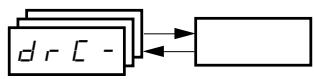
| Code | Factory Setting | Custom Setting |
| b F r | 50 Hz | Hz |
| U n 5 | Varies with drive rating | V |
| F r 5 | 50 Hz | Hz |
| n C r | Varies with drive rating | A |
| n 5 P | Varies with drive rating | RPM |
| C 0 5 | Varies with drive rating | |
| r 5 C | nO |
| Code | Factory Setting | Custom Setting |
| t U 5 | tAb | |
| U F t | n | |
| n r d | YES | |
| S F r | 4 kHz | kHz |
| t F r | 60 Hz | Hz |
| S r F | nO |
I/O Menu

| Code | Factory Setting | Custom Setting |
| E C E | 2C ATV31********A: LOC | |
| E C E | trn | |
| r r 5 | if tCC = 2C, LI2 if tCC = 3C, LI3 if tCC = LOC: nO | |
| E R L E | 4 mA | mA |
| E R H E | 20 mA | mA |
| Code | Factory Setting | Custom Setting |
| R 0 I E | 0A | |
| d 0 | nO | |
| r 1 | FLt | |
| r 2 | nO |
Control Menu

| Code | Factory Setting | Custom Setting |
| L R C | L1 | |
| F r l | Al1 AIP for ATV31********A | |
| F r 2 | nO | |
| r F C | Fr1 | |
| C H C F | SIM | |
| C d l | tEr LOC for ATV31********A |
| Code | Factory Setting | Custom Setting |
| C d E | Mdb | |
| C C S | Cd1 | |
| C O P | nO | |
| L C C | nO | |
| P 5 E | YES | |
| r D E | dFr |

These parameters only appear if the corresponding function is enabled.
Application Functions Menu

| Code | Factory Setting | Custom Setting | |
| r PC - | r P t | LIn | |
| t H 1 | 10% | % | |
| t H 2 | 10% | % | |
| t H 3 | 10% | % | |
| t H 4 | 10% | % | |
| R C C | 3 s | s | |
| d E C | 3 s | s | |
| r P S | nO | ||
| F r t | 0 | Hz | |
| R C 2 | 5 s | s | |
| d E 2 | 5 s | s | |
| b r R | YES | ||
| S t C - | S t t | Stn | |
| F S t | nO | ||
| d C F | 4 | ||
| d C I | nO | ||
| I d C | 0.7 In | A | |
| t d C | 0.5 s | s | |
| n S t | nO | ||
| R d C - | R d C | YES | |
| t d C I | 0.5 s | s | |
| S d C I | 0.7 In 1 | A | |
| t d C 2 | 0 s | s | |
| S d C 2 | 0.5 In 1 | A | |
| S H I - | S H 2 | Al2 | |
| S H 3 | nO | ||
| Code | Factory Setting | Custom Setting | |
| JOG- | JOG | If tCC = 2C: nO If tCC = 3C: LI4 If tCC = LOC: nO | |
| JGF | 10 Hz | Hz | |
| UPd- | USP | nO | |
| dSP | nO | ||
| SBr | nO | ||
| PI- | PIF | nO | |
| rPG | 1 | ||
| rIG | 1 | ||
| FB5 | 1 | ||
| PIC | nO | ||
| Pr2 | nO | ||
| Pr4 | nO | ||
| rP2 | 30% | % | |
| rP3 | 60% | % | |
| rP4 | 90% | % | |
| rSL | 0 | ||
| Pll | nO | ||
| rPI | 0% | % | |
| bLC- | bLC | nO | |
| brL | Varies with drive controller rating | Hz | |
| Ibr | A | ||
| brt | 0.5 s | s | |
| bEn | nO | Hz | |
| bEt | 0.5 s | s | |
| bIP | nO | ||
| LC2- | LC2 | nO | |
| LC2 | 1.5 In1 | A | |
1 In corresponds to the nominal drive current indicated in the ATV31 Installation Manual and on the drive controller nameplate.

These parameters only appear if the corresponding function is enabled. They can also be accessed in the SET- menu.
Application Functions Menu (Continued)

| Code | Factory Setting | Custom Setting | |
| P55- | P52 | If tCC = 2C: LI3 | |
| If tCC = 3C: LI4 | |||
| If tCC = LOC: LI3 | |||
| P54 | If tCC = 2C: LI4 | ||
| If tCC = 3C: nO | |||
| If tCC = LOC: LI4 | |||
| P58 | nO | ||
| P516 | nO | ||
| 5P2 | 10 Hz | Hz | |
| 5P3 | 15 Hz | Hz | |
| 5P4 | 20 Hz | Hz | |
| 5P5 | 25 Hz | Hz | |
| 5P6 | 30 Hz | Hz | |
| 5P7 | 35 Hz | Hz | |
| 5P8 | 40 Hz | Hz | |
| 5P9 | 45 Hz | Hz | |
| 5P10 | 50 Hz | Hz | |
| 5P11 | 55 Hz | Hz | |
| 5P12 | 60 Hz | Hz | |
| 5P13 | 70 Hz | Hz | |
| 5P14 | 80 Hz | Hz | |
| 5P15 | 90 Hz | Hz | |
| 5P16 | 100 Hz | Hz | |
| Code | Factory Setting | Custom Setting | |
| C HP - | C HP | nO | |
| U n 52 | Varies with drive controller rating | V | |
| F r 52 | 50 Hz | Hz | |
| n C r 2 | Varies with drive controller rating | A | |
| n S P 2 | RPM | ||
| C O 52 | |||
| U F E 2 | n | ||
| U F r 2 | 20% | % | |
| F L G 2 | 20% | % | |
| S E A 2 | 20% | % | |
| S L P 2 | 100 Hz | Hz | |
| L 5 E - | L R F | nO | |
| L A r | nO | ||
| L H 5 | nSt | ||

These parameters only appear if the corresponding function is enabled. They can also be accessed in the SET- menu.
Fault Menu
| Code | Factory Setting | Custom Setting |
| R E r | nO | |
| E R r | 5 | |
| r S F | nO | |
| F L r | nO | |
| E E F | nO | |
| E P L | YES | |
| D P L | YES | |
| I P L | YES | |
| D H L | YES | |
| D L L | YES |
| Code | Factory Setting | Custom Setting |
| S L L | YES | |
| C D L | YES | |
| t n L | YES | |
| L F L | nO | |
| L F F | 10 Hz | Hz |
| d r n | nO | |
| S E P | nO | |
| I n H | nO | |
| r P r | nO |

These parameters only appear if the corresponding function is enabled.
Communication Menu

| Code | Factory Setting | Custom Setting |
| R d d | 1 | |
| t b r | 19200 | |
| t F D | 8E1 | |
| t E D | 10 s | s |
| R d C D | 0 |
| Code | Factory Setting | Custom Setting |
| b d C O | 125 | |
| F L O | nO | |
| F L O C | AI1 AIP for ATV31********A |
INDEX OF PARAMETER CODES
| Code | See Page: | Code | See Page: | Code | See Page: |
| R C 2 | 26 | F r E | 52 | r F r | 85 |
| R C C | 26 | F S E | 53 | r I G | 68 |
| R d C | 55 | F t d | 29 | r O E | 49 |
| R d C D | 82 | H S P | 26 | r P 2 | 68 |
| R d d | 82 | I b r | 72 | r P 3 | 68 |
| R I I A | 86 | I d C | 53 | r P 4 | 68 |
| R I 2 A | 86 | I n H | 81 | r P G | 68 |
| R I 3 A | 86 | I P L | 80 | r P I | 69 |
| R O I E | 86 | I t H | 26 | r P I | 85 |
| R E r | 79 | J F E | 28 | r P r | 81 |
| b d C D | 82 | J G F | 28 | r P S | 52 |
| b E n | 72 | J O G | 60 | r P E | 51 |
| b E t | 72 | J P F | 28 | r r S | 33 |
| b F r | 30 | L A C | 46 | r S C | 31 |
| b I P | 72 | L A F | 76 | r S F | 79 |
| b L C | 72 | L A r | 76 | r S L | 69 |
| b r A | 52 | L A S | 76 | r t H | 85 |
| b r L | 72 | L C E | 73 | S A E | 56 |
| b r E | 72 | L C C | 48 | S A E | 56 |
| C C S | 48 | L C r | 85 | S C S | 32 |
| C d I | 47 | L F F | 81 | S d C I | 55 |
| C d Z | 47 | L F L | 81 | S d C Z | 55 |
| C H C F | 47 | L F r | 85 | S d S | 29 |
| C H P | 74 | L F E | 85 | S F r | 29 |
| C L Z | 73 | L I I A | 86 | S L L | 81 |
| C L I | 28 | L I 2 A | 86 | S L P | 27 |
| C O d | 86 | L I 3 A | 86 | S L P Z | 75 |
| C O P | 48 | L I 4 A | 86 | S P I D | 59 |
| C O S | 30 | L I 5 A | 86 | S P I I | 59 |
| C O S Z | 75 | L I 6 R | 86 | S P I Z | 59 |
| C r H Z | 34 | L I 5 | 86 | S P I E | 59 |
| C r L Z | 34 | L S P | 26 | S P I Y | 59 |
| C t d | 29 | n C r | 30 | S P I S | 59 |
| d C F | 53 | n C r Z | 74 | S P I E | 59 |
| d C I | 53 | n r d | 32 | S P Z | 59 |
| d E Z | 52 | n S P | 30 | S P E | 59 |
| d E C | 52 | n S P Z | 74 | S P Y | 59 |
| d O | 34 | n S E | 54 | S P S | 59 |
| d r n | 81 | O H L | 80 | S P E | 59 |
| d S P | 63 | O L L | 80 | S P Y | 59 |
| E P L | 80 | O P L | 80 | S P B | 59 |
| E r C D | 82 | O P r | 85 | S P G | 59 |
| E E F | 80 | O E r | 85 | S P d I | 85 |
| F b S | 28 | P I C | 68 | S P d Z | 85 |
| F C S | 32 | P I F | 68 | S P d E | 85 |
| F L G | 27 | P r Z | 68 | S r F | 32 |
| F L G Z | 28 | P r Y | 68 | S t H | 27 |
| F L O | 82 | P S I E | 59 | S t H Z | 75 |
| F L O C | 83 | P S Z | 58 | S t P | 81 |
| F L r | 80 | P S Y | 58 | S t r | 63 |
| F r I | 46 | P S B | 58 | S t E | 53 |
| F r Z | 46 | P S E | 49 | t H I | 26 |
| F r H | 85 | r I | 34 | t H Z | 26 |
| F r S | 30 | r Z | 34 | t H E | 26 |
| F r S Z | 74 | r F C | 47 | t H Y | 26 |
| Code | See Page: |
| b r | 79 |
| b r | 82 |
| c c | 33 |
| c t | 33 |
| d c | 27 |
| d c l | 27 |
| d c 2 | 27 |
| F r | 32 |
| H d | 85 |
| H r | 85 |
| L 5 | 28 |
| t d | 29 |
| t 0 | 82 |
| U n | 31 |
| U 5 | 31 |
| U 5 | 86 |
| U d P | 86 |
| U F r | 27 |
| U F r 2 | 75 |
| U F t | 31 |
| U F t 2 | 75 |
| U L n | 85 |
| U n 5 | 30 |
| U n 5 2 | 74 |
| U 5 P | 63 |
INDEX OF FUNCTIONS
| Function | See Page: |
| +/- speed | 61 |
| 2-wire/3-wire control | 33 |
| Analog/logic output AOC/AOV | 34 |
| Automatic restart | 79 |
| Automatic DC injection | 55 |
| Brake control | 70 |
| CANopen: Drive address | 82 |
| Catch on the fly (automatically catch a spinning load on ramp) | 80 |
| Control and reference channels | 36 |
| Control channel switching | 48 |
| Current limit | 28 |
| DC injection via logic input | 53 |
| Deceleration ramp adaptation | 52 |
| Drive thermal protection | 13 |
| Drive ventilation | 13 |
| Fast stop via logic input | 53 |
| Flying restart (automatic catching a spinning load on ramp) | 80 |
| Forced local mode | 82 |
| Freewheel stop via logic input | 54 |
| Function access level | 46 |
| Jog operation | 60 |
| Management of limit switch | 76 |
| Modbus: Drive address | 82 |
| Motor control auto-tuning | 31 |
| Motor switching | 74 |
| Motor thermal protection | 14 |
| Motor thermal protection - max. thermal current | 26 |
| PI regulator | 64 |
| Preset speeds | 57 |
| Ramp switching | 52 |
| Ramps | 51 |
| Reference switching | 47 |
| Relay R1 | 34 |
| Relay R2 | 34 |
| Reset of current fault | 79 |
| Return to factory settings/restore configuration | 32 |
| Saving the configuration | 32 |
| Selection of the type of voltage/frequency ratio | 31 |
| Skip frequency | 28 |
| Stop modes | 53 |
| Summing inputs | 56 |
| Switching for second current limit | 73 |
| Switching frequency | 29 |
SECCION 1: INTRODUCCION
SECTION 1: INTRODUCTION
ASSISTANCE AUX PRODUITS
DANGER
RECOMMANDATIONS PRÉLIMINAIRIES
Précautions
Electrical equipment should be installed, operated, serviced, and maintained only by qualified personnel. No responsibility is assumed by Schneider Electric for any consequences arising out of the use of this material.
Schneider Electric USA
8001 Hwy 64 East
Raleigh, NC 27545
1-888-SquareD (1-888-778-2733)
www.us SQUARED.com
VVDED303042NAR6/04
Replaces VVDED303042NA dated 05/2004
© 2004 Schneider Electric
All Rights Reserved
© 2004 Schneider Electric
19 Waterman Avenue, M4B 1 Y2
Toronto, Ontario
1-800-565-6699
www.schneider-electric.ca
VVDED303042NAR6/04
RemplaceVVDED303042NA en date de 05/2004
© 2004 Schneider Electric