
ICA 1200 - Amplifier PEAVEY - Free user manual and instructions
Find the device manual for free ICA 1200 PEAVEY in PDF.

| Product type | Professional audio amplifier |
| Brand | Peavey |
| Model | ICA 1200 |
| Category | Amplifier |
| Format | 2U or 3U 19" rack (depth 400 mm) |
| Weight | Approximately 10 kg (estimate) |
| Power supply | IEC connector, voltage per model (e.g., 230 V AC) |
| Output power | 4 ohms / 70.7 V / 100 V (depending on model) |
| Operating modes | Stereo, parallel, bridge |
| Audio inputs | 4-pin Phoenix block per channel (balanced/unbalanced) |
| Speaker outputs | Connection block for bare wires or fork terminals (max 2 cables 6 mm² per terminal) |
| Built-in protections | Clip limiter, load fault correction (LFC), thermal protection, short circuit, DC, progressive startup |
| Cooling | Variable-speed fan, rear grille, front exhaust |
| Standby consumption | Idle (low consumption) |
| Hibernation function | Automatic consumption reduction after 1 minute without signal |
| Remote control | 12-24 V DC connector for sequential power on/off |
| LED indicators | Power, Signal, Protection/Clip, LFC |
| Safety | Circuit breaker, do not open, refer servicing to qualified technician |
| Maintenance and cleaning | Disconnect before cleaning, do not expose to humidity |
| Spare parts and repairability | No user-serviceable parts, contact Peavey customer service |
| General information | Manual available in French, English, German, Spanish |
Frequently Asked Questions - ICA 1200 PEAVEY
User questions about ICA 1200 PEAVEY
0 question about this device. Answer the ones you know or ask your own.
Ask a new question about this device
Download the instructions for your Amplifier in PDF format for free! Find your manual ICA 1200 - PEAVEY and take your electronic device back in hand. On this page are published all the documents necessary for the use of your device. ICA 1200 by PEAVEY.
USER MANUAL ICA 1200 PEAVEY
Intended to alert the user to the presence of uninsulated "dangerous voltage" within the product's enclosure that may be of sufficient magnitude to constitute a risk of electric shock to persons.

Intended to alert the user of the presence of important operating and maintenance (servicing) instructions in the literature accompanying the product.
CAUTION: Risk of electrical shock — DO NOT OPEN!
CAUTION: To reduce the risk of electric shock, do not remove cover. No user serviceable parts inside. Refer servicing to qualified service personnel.
WARNING: To prevent electrical shock or fire hazard, do not expose this appliance to rain or moisture. Before using this appliance, read the operating guide for further warnings.

Congratulations on your purchase of an Architectural Acoustics ICA™ (Industrial Contractor Amplifier) from Peavey Electronics. Please read this manual carefully, especially the IMPORTANT SAFETY INSTRUCTIONS on page 18. It contains information vital to safe operation of the power amplifier. Also, please fill out and return the enclosed product registration card.
ICA Series amplifiers represent new levels of value and flexibility never before offered to the contracting market. The ICA Series features models specifically designed to drive 4-ohm outputs, 70.7-volt outputs, and 100-volt outputs. 70.7 and 100-volt outputs can be driven directly, eliminating the need for transformers or autoformers. These amplifiers cover almost every installed or distributed sound power requirement imaginable.
ICA Series amplifiers are ruggedly built from high-quality components and feature comprehensive protection circuits to protect your amplifier from those "real world" occurrences.
If you need setup or operational assistance for this product, please call the Peavey Electronics Customer Service Department or your local Peavey Electronics representative. We appreciate suggestions that may help us improve our products and/or service.
UNPACKING
Inspect the amplifier during unpacking. If you find any damage, notify your dealer immediately. Only the consignee may institute a claim with the carrier for damage incurred during shipping. Be sure to save the carton and all packing materials. Should you ever need to ship the unit back to Peavey Electronics, one of its service centers, or the dealer; use only the original factory packing.
INSTALLATION AND MOUNTING
ICA Series amplifiers are 2 or 3-rack-space units of 15 3/4'' (400 mm) depth that mount in a standard 19" rack. On all amplifiers, front panel mounting holes are provided.
BASIC SETUP
- Rack mount the amplifier in the location where it is to be used, remembering to allow for adequate access and cooling space. For more information, see the sections on INSTALLATION AND MOUNTING and COOLING REQUIREMENTS.
- Make input connections to the plugable terminal blocks on the rear panel. Use the proper connections for stereo, parallel, bridged mono, and grounding configuration. See the sections on SIGNAL MODE CONFIGURATION and INPUT MODULE CONNECTIONS for more information.
- Connect speakers to the output barrier strip. Be sure to make the correct output connections for stereo, parallel or bridged mono configuration. See the section on SPEAKER OUTPUT CONNECTIONS for more information.
- Make power connections, allowing for proper current draw. See the sections on IEC POWER CONNECTOR and AC MAINS CIRCUIT SIZE REQUIREMENTS for more information.
- Turn the front panel 3-position AC POWER switch to ON and bring up the back panel LEVEL (gain) attenuators to the desired levels.
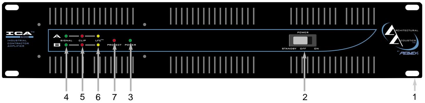
1. RACK MOUNTING EARS
These mounting holes are provided on each front mounting ear.
2. 3-POSITION AC POWER SWITCH
A 3-position switch is on the front panel. Sequential remote turn-on capability is a standard feature. With the switch pushed towards the outside position, the amplifier is ON. The middle position is OFF, and the inside position is marked STANDBY. When switched to STANDBY, the amplifier may be activated by the sequential turn-on circuit. See the section on SEQUENTIAL TURN-ON / TURN-OFF for more information.
3. POWER LED
The POWER LED illuminates when the amplifier is turned on.
4. SIGNAL LED
Each channel has a SIGNAL LED that illuminates when the amplifier output exceeds 1 volt.
5. CLIP LED
Each channel has a CLIP LED that illuminates at the clipping point, and indicates that internal circuitry is reducing amplifier gain to allow full power. See the section on PROTECTION FEATURES for more information.
6. LFC™ LED
Each channel has a LFC (Load Fault Correction) LED. This LED illuminates when the amplifier channel detects an abnormal load condition. Internal circuitry will instantaneously reduce the channel gain to allow the amplifier to operate at a safe level into the abnormal load. See the section on PROTECTION FEATURES for more information.
7. PROTECT LED
If the amplifier has just been turned on or has detected a fault condition, the speaker output relays will open, illuminating this LED.
BACK PANEL FEATURES
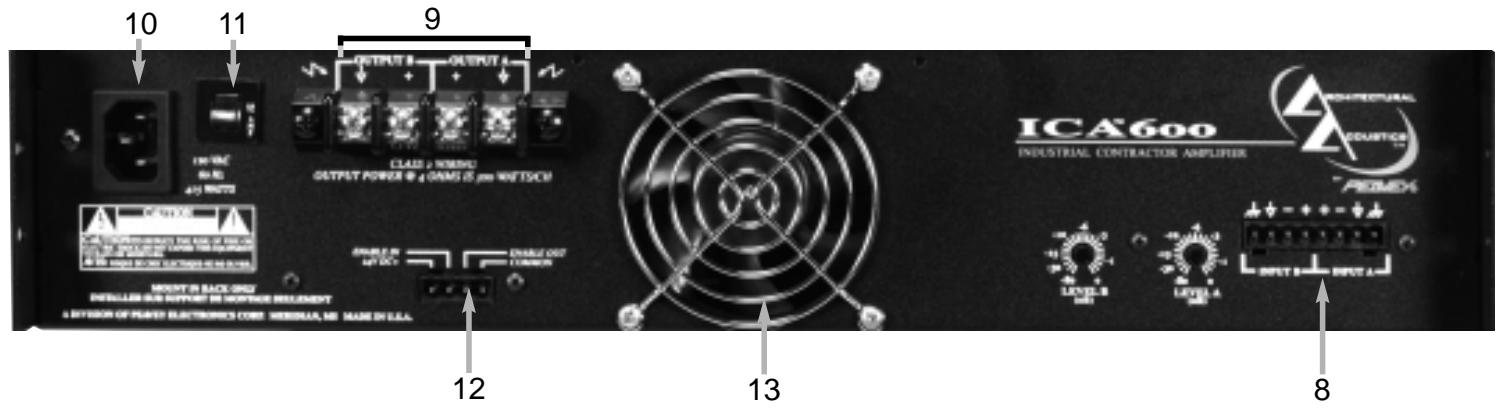
8. INPUT SECTION
The ICA™ Series comes standard with plugable input connectors and individual channel rotary attenuators. Connections at the input connector permit the audio signal ground to be connected or lifted from the chassis ground.
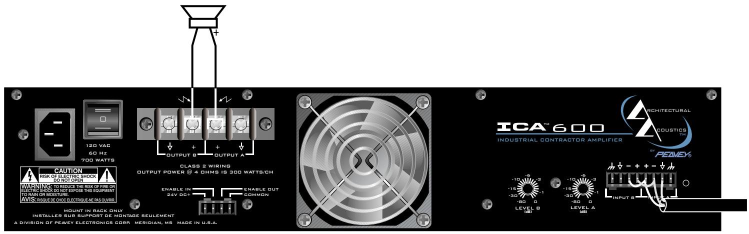
9. OUTPUT BARRIER STRIP
A barrier strip is provided for connection of loudspeakers with bare wire or spade lug connectors. This barrier strip can accommodate up to two 10-gauge wires per terminal.
10. IEC POWER CONNECTOR
A standard IEC power connector is located at the upper left corner of the amplifier rear panel. An AC mains cord having an appropriate AC plug for the intended operating voltage is included.
NOTE: FOR UK ONLY
If the colors of the wires in the mains lead of this unit do not correspond with the colored markings identifying the terminals in your plug, proceed as follows: (1) The wire that is colored green and yellow must be connected to the terminal that is marked by the letter E, the earth symbol, colored green, or colored green and yellow. (2) The wire that is colored blue must be connected to the terminal that is marked with the letter N or the color black. (3). The wire that is colored brown must be connected to the terminal that is marked with the letter L or the color red.
11. CIRCUIT BREAKER
A resettable, protective AC circuit breaker is located at the upper left of the amplifier back panel. If the breaker has tripped, push it back in to return the amplifier to operating condition. If the breaker continues to trip, the amplifier needs servicing. Do not continue to reset the breaker because severe internal damage and safety hazards could occur!
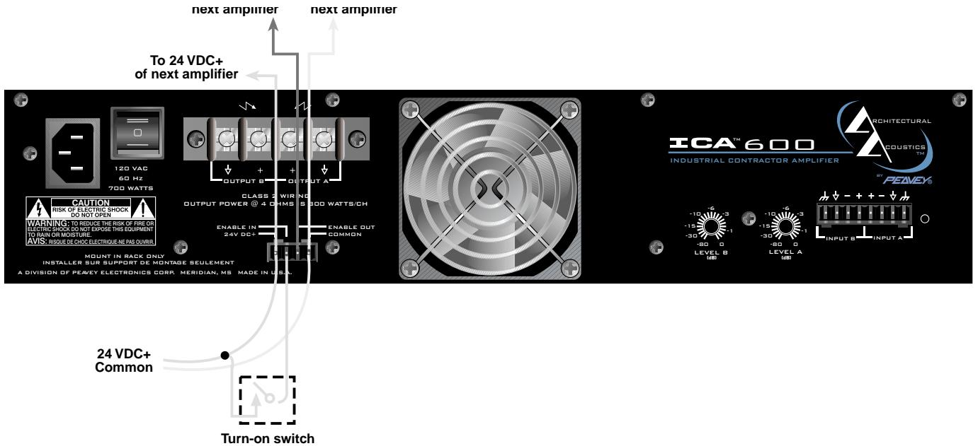
12. SEQUENTIAL TURN-ON CONNECTOR
The ICA™ Series comes standard with remote-controllable sequential turn on enabled by setting the front power switch to STANDBY. The amplifier is activated by applying a voltage between 12 to 24 volts DC to the rear-mounted, 4-pin plugable terminal, and connecting the ENABLE terminal to the 24 V DC+ terminal. When no voltage is present or the ENABLE connection is opened, the amplifier will switch off. Other ICA Series amplifiers can be "daisy chained" by connecting all 24 V DC+ terminals together, all COMMON terminals together, and
connecting the ENABLE OUT to the ENABLE IN of the next amplifier. A mating connector is shipped with the amplifier.
13. FAN GRILL
A continuously variable-speed DC fan supplies cool air into the amplifier. Do not block this intake! The fan operates only when the amplifier heat sinks require cooling.
OPERATION
AC MAINS CIRCUIT SIZE REQUIREMENTS
Power requirements for ICA™ amplifiers are rated at "idle", 1/8 power ("typical" music conditions), 1/3 power, and maximum rated power. The maximum power current draw rating is limited by the amplifier's circuit breaker. Consult the specification sheet for the current that each amplifier will demand. AC mains voltage must be the same as that indicated on the back of the amplifier. Damage caused by connecting the amplifier to improper AC voltage is not covered by any warranty. NOTE: Always turn off and disconnect the amplifier from the mains voltage before making audio connections. As an extra precaution, have the input attenuators turned down during initial power up.
A COOLING REQUIREMENTS
10 ICA Series amplifiers use a forced-air cooling system to maintain a low, even operating temperature. Cooling air is drawn by a continuously variable-speed fan mounted on the back panel, and exhausts through slots on the front panel. The fan will remain inactive until internal operating temperature rises above 45° C (113° F). Make sure there is enough space around the back of the amplifier to allow air to enter. NOTE: If the amplifier is rack mounted, do not use doors or covers on the front or back without pressurizing the back of the rack. Whatever type of rack you are using, make sure that heated air can escape freely, and that there is no resistance to the intake of cool air through the back grill. Intake and exhaust air must flow without resistance.
HIBERNATION
All ICA Series amps feature Hibernation circuitry. Current draw and thermal emissions are at a minimum when the absence of input signal is sensed for more than a minute. Once signal is present, Hibernation instantly restores the amplifier to normal. Current draw specifications while Hibernation is active are included in specifications under Idle Current Draw.
THERMAL EMISSIONS
The system installer or designer should specify system cooling needs. Refer to the specifications at the back of this manual for specific thermal emissions figures.
INPUT CONNECTIONS
The input connector accepts balanced and unbalanced audio signals. For use with an unbalanced source, tie the inverting (-) input to ground by installing a jumper to the signal ground connection. If the inverting input is left floating, a 6 dB loss in gain will result.
ICA™ Series amplifiers are configured for Stereo (2-channel), Bridged Mode, or Parallel Mode operation at the input connector.
To send the same signal to both channels (Parallel Mode), connect the input signal to CHANNEL A via the input connector. Run jumpers from the positive and negative terminals of the CHANNEL A input connector to the respective terminals of CHANNEL B. Both channels then share the CHANNEL A input signal but will operate independently. Speakers are connected as in Stereo Mode.
Bridged Mode converts the amplifier into a single-channel unit with a power rating equal to the sum of both channel power ratings, and at a load rating twice that of the single-channel rating. In Bridged Mode, the channels operate at opposite polarity of each other so that one channel "pushes" and the other "pulls" equally. Signal is connected to the input connector with one jumper connecting the positive (+) terminal of Input A to the negative (-) terminal of Input B, and another jumper connecting the negative (-) terminal of Input A to the positive (+) terminal of Input B. Both channel attenuators (A & B) are used to control signal level, and both must be at the same level, preferably at 0 dB attenuation. The speakers are connected only to the designated "+" output terminals. NEVER ground either side of the speaker cable when the amplifier is in Bridged Mode as both sides are "hot". If an output patch panel is used, all connections must be isolated from each other and from the panel. For ICA Series amplifiers, the minimum nominal load impedance in Bridged Mode is 8 ohms; this is the equivalent of driving both channels at 4 ohms. Driving loads of less than 8 ohms may activate the LFC circuit and may also cause a thermal protect condition. NOTE: Regardless of operating mode, NEVER connect amplifier outputs together!
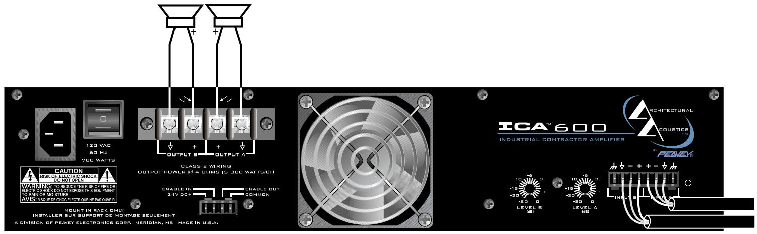
STEREO MODE CONNECTION DIAGRAM
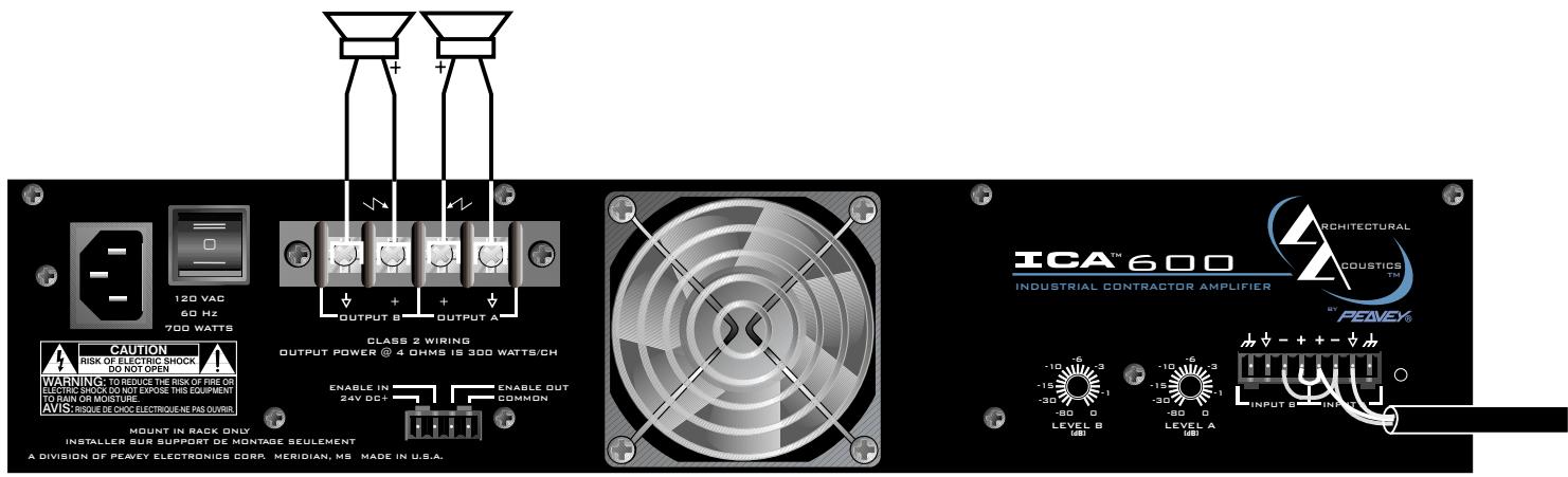
PARALLEL MODE DIAGRAM

SPEAKER OUTPUT CONNECTIONS
Speakers are connected using the output barrier strip connectors. Spade lugs, ring tongues or bare wire may be connected to the output barrier strip elements. The barrier strip can accommodate up to two 10-guage wires per terminal. Make sure the amplifier is turned off before you change any output connections or jumpers. Consult the Wire Gauge Chart at the back of this manual to find a suitable wire gauge to minimize losses of power in the speaker cables. Also, make sure that the load impedance is not lower than that rated for the amplifier.
Connections at the input connector permit the audio signal ground to be connected or lifted from the chassis ground. When possible, the shield of the signal source connecting cable should connect to the chassis ground. In some cases, however, particularly if an amplifier is being installed in an existing system, this may result in a ground loop. If this happens, connect the shield to the signal ground only. The chassis ground also connects to the AC ground internally. If the cable shield is connected to the signal ground only, it will be clamped to +/- 0.6 V above or below chassis/AC ground.
PROTECTION FEATURES
The ICA™ Series incorporates protection features derived from Peavey's extensive experience with reliability. The amplifiers are ruggedly built from high-quality components and feature comprehensive protection circuits to protect your amplifier from those "real world" occurrences.
CLIP LIMITING
At the amplifier's full power, or clipping point, the channel gain will automatically be reduced, guarding the loudspeakers against damaging high power and continuous square waves that would otherwise be produced. This is indicated by illumination of the CLIP LED. Normal program transients will not trigger Clip Limiting, only steady or excessive clipping will. Operation is virtually transparent in use and full signal bandwidth is maintained.
LOAD FAULT CORRECTION
LFC is an innovative circuit that will instantaneously reduce channel gain to allow the amplifier to operate at a safe level into an abnormal load. LFC activation is indicated by illumination of the LFC LED. Moderate activation of LFC is inaudible in normal use. In addition, if extreme low impedance or a short circuit is encountered during high signal level conditions, the amplifier's output relay will open.
FADE-IN PROTECTION
This feature operates every time the amplifier is turned on, or after a protect condition. During turn on, the amplifier goes into protect mode and leaves the speaker load disconnected until the amplifier determines that the operating status is normal. The Fade-In circuit attenuates the signal during the initial turn on or protect operation. After relay release, channel gain gradually increases to the attenuator setting to avoid unnecessary stress on the loudspeakers.
THERMAL PROTECTION
If the heatsink or power transformer reaches an abnormally high temperature, the amplifier will protect itself by disconnecting the speaker load until the amplifier returns to a normal temperature. During this time, the PROTECT LED will illuminate, and the cooling fan will operate at maximum speed.
SHORT CIRCUIT
If an output is shorted, the LFC TM , speaker relay and thermal circuits will automatically protect the amplifier. The LFC circuit senses the short circuit as an abnormal load condition and reduces the channel gain to a safe level for the load. In extreme or severe conditions, the speaker relays will disconnect the load and initiate a power-on start-up sequence.
DC VOLTAGE PROTECTION
If an amplifier channel detects DC voltage or subsonic signals at its output terminals, the speaker relay will immediately open to prevent loudspeaker damage. The PROTECT LED will illuminate as notification of this condition.
SEQUENTIAL TURN-ON / TURN-OFF
The ICA™ Series comes standard with remote sequential turn-on. The amplifier front power switch is set to STANDBY. An external direct plug-in power supply unit providing a nominal voltage between 12 to 24 volts DC must be applied to the 4-pin plugable terminal on the rear panel. The ENABLE OUT is connected to the ENABLE IN of the next amplifier. ICA Series amplifiers are bussed or "daisy chained" together in parallel and connected to the DC supply by connecting all 24 V DC+ terminals together and all COMMON terminals together. The first amplifier in the chain requires an SPST closure between its 24 V DC+ terminal and ENABLE OUT terminal to initiate the power turn-on sequence and keep the amplifiers in the chain powered on.
Sequential Turn-On / Turn-Off Wiring
WIRE GAUGE CHART
| Cable Length (Feet) | Stranded Wire Gauge (AWG) | Power Loss Into 8 ohms | Power Loss Into 4 ohms | Power Loss Into 2 ohms |
| 5' | 18 AWG | .79% | 1.58% | 3.16% |
| 16 | .5 | 1.0 | 2.0 | |
| 14 | .31 | .62 | 1.24 | |
| 12 | .20 | .40 | .80 | |
| 10 | .125 | .25 | .50 | |
| 10' | 18 AWG | 1.58% | 3.16% | 6.32% |
| 16 | 1.0 | 2.0 | 4.00 | |
| 14 | .62 | 1.25 | 2.50 | |
| 12 | .40 | .80 | 1.6 | |
| 10 | .25 | .50 | 1.0 | |
| 40' | 18 AWG | 8.0% | 12.6% | 25.2% |
| 16 | 4.0 | 8.0 | 16.0 | |
| 14 | 2.5 | 5.0 | 10.0 | |
| 12 | 1.60 | 3.2 | 6.4 | |
| 10 | 1.0 | 2.0 | 4.0 | |
| 8 | .625 | 1.25 | 2.50 | |
| 80' | 16 AWG | 8.0% | 16.0% | 32.0% |
| 14 | 5.0 | 10.0 | 20.0 | |
| 12 | 3.2 | 6.4 | 12.8 | |
| 10 | 2.0 | 4.0 | 8.0 |
ICA™ 600 SPECIFICATIONS
Rated Power (2 X 4 ohms):
300 watts @ 20 Hz - 20 kHz, both channels driven at < 0.1% THD
Rated Power (2 x 8 ohms):
200 watts @ 20 Hz - 20 kHz at
< 0.05% THD
Rated Power (1 x 4 ohms):
360 watts @ 1 kHz at < 0.015% THD
Rated Power (1 x 8 ohms):
275 watts @ 1 kHz at < 0.005%
THD
Minimum Load Impedance:
4 ohms
Maximum RMS Voltage Swing:
57 volts
Frequency Response:
10 Hz - 25 kHz; +0, -3 dB at 1 watt
Power Bandwidth:
10 Hz - 100 kHz; +0, -3 dB at rated power
THD (2 x 4 ohms):
<0.1% @ 300 W from 20 Hz - 20 kHz
with both channels driven
THD (2 x 8 ohms):
<0.05% @ 200 W from 20 Hz -
20 kHz with both channels driven
THD (1 x 4 ohms):
<0.01% @ 350 W @ 1 kHz
THD (1 x 8 ohms):
<0.005% @ 275 W @ 1 kHz
SMPTE IMD:
<0.1% 60 Hz and 7 kHz, 300 W @
4 ohms
Slew Rate:
30 V/μs
Damping Factor (8 ohms):
450:1 @ 20 Hz - 1 kHz
Input CMRR:
-65 dB @ 1 kHz
Voltage Gain:
x40 (32 dB)
Input Sensitivity:
.866 volts @ 4 ohms, 1 volt @
8 ohms
Input Impedance:
20 k ohms, balanced
Hum and Noise:
-108 dB, "A" weighted referenced
to rated power @ 8 ohms
Crosstalk:
>75 dB, "A" weighted referenced to
rated power @ 8 ohms
Current Draw @ 1/8 power:
670 watts @ 4 ohms, 460 watts @
8 ohms
Current Draw @ 1/3 power:
1,055 watts @ 4 ohms, 650 watts @
8 ohms
Idle Current Draw:
30 watts in Standby Mode
Maximum Current Draw:
1,622 watts @ 4 ohms, 1,010 watts
@ 8 ohms
Thermal Emissions (BTU/hr.):
625 @ 1/3 power 4 ohms,
500 @ 1/3 power 8 ohms,
395 @ 1/8 power 4 ohms,
350 @ 1/8 power 8 ohms
Cooling:
80 mm DC fan, off until heatsinks
reach 45° C, then variable speed
Controls:
2 rear panel attenuators, sequential
turn-on / off
Indicator LEDs:
2 Clip, 2 Signal, 2 LFC, 1 Protect,
1 Power
Protection:
Temp., DC, turn-on bursts, subsonic,
incorrect load or short
Connectors:
8-pin plugable signal input, 4-pin
plugable sequential power,
4-terminal barrier strip, IEC AC
power connector
Construction:
All steel; 16 ga. chassis, 18 ga. top,
12 ga. rack ears
Dimensions:
3.48" x 19" x 16.4"
88.4 mm x 483 mm x 416.6 mm
Gross Weight:
33.6 lbs. (15.25 kg)
Net Weight:
30.2 lbs. (13.7 kg)
ICATM1200 SPECIFICATIONS
Rated Power (2 X 4 ohms):
600 watts @ 20 Hz - 20 kHz, both channels driven at < 0.1% THD
Rated Power (2 X 8 ohms):
400 watts @ 20 Hz - 20 kHz, both channels driven at < 0.05% THD
Rated Power (1 X 4 ohms):
700 watts @ 1 kHz at < 0.008% THD
Rated Power (1 X 8 ohms):
425 watts @ 1 kHz at < 0.005% THD
Minimum Load Impedance:
4 ohms
Maximum RMS Voltage Swing:
70 volts
Frequency Response:
10 Hz - 25 kHz; +0, -.3 dB at 1 watt
Power Bandwidth:
10 Hz - 100 kHz; +0, -3 dB at rated power
THD (2 x 4 ohms):
<0.1% @ 600 W from 20 Hz - 20 kHz with both channels driven
THD (2 x 8 ohms):
<0.05% @ 400 W from 20 Hz -
20 kHz with both channels driven
THD (1 X 4 ohms):
<0.008% @ 700 W @ 1 kHz
THD (1 X 8 ohms):
<0.005% @ 425 W @ 1 kHz
SMPTE IMD:
<0.1% 60 Hz and 7 kHz, 600 W @
4 ohms
Slew Rate:
30 V / µs
Damping Factor (8 ohms):
350:1 @ 20 Hz - 1 kHz
Input CMRR:
-
65 dB @ 1 kHz
Voltage Gain:
x40 (32 dB)
Input Sensitivity:
1.22 volts @ 4 ohms, 1.41 volts @ 8 ohms
Input Impedance:
20 k ohms, balanced
Hum and Noise:
-110 dB, "A" weighted referenced to rated power
Crosstalk:
> -65 dB, "A" weighted referenced to rated power
Current Draw @ 1/8 power:
950 watts @ 4 ohms, 725 watts @ 8 ohms
Current Draw @ 1/3 power:
1,750 watts @ 4 ohms, 1,150 watts @ 8 ohms
Idle Current Draw:
32 watts in Standby Mode
Maximum Current Draw:
2,670 watts @ 4 ohms (time limited by breaker), 1,725 watts @ 8 ohms
Thermal Emissions (BTU/hr.):
1,100 @ 1/3 power 4 ohms,
850 @ 1/3 power 8 ohms,
635 @ 1/8 power 4 ohms,
540 @ 1/8 power 8 ohms
Cooling
120 mm DC fan, off until heatsinks reach 45° C, then variable speed
Controls:
2 rear panel attenuators, sequential turn-on / off
Indicator LEDs:
2 Clip, 2 Signal, 2 LFC, 1 Protect, 1 Power
Protection:
Temp., DC, turn-on bursts, subsonic, incorrect load or short
Connectors:
8-pin plugable signal input, 4-pin plugable sequential power,
4-terminal barrier strip, IEC AC power connector
Construction:
All steel; 16 ga. chassis, 18 ga. top, 12 ga. rack ears
Dimensions:
5.25" x 19" x 16.4"
133 mm x 483 mm x 416.6 mm
Gross Weight:
51.4 lbs. (23.3 kg)
Net Weight:
45 lbs. (20.4 kg)
ICA™ 2400 SPECIFICATIONS
Rated Power (2 x 4 ohms):
1200 watts @ 20 Hz - 20 kHz both channels driven at < 0.1% THD
Rated Power (2 x 8 ohms):
800 watts @ 20 Hz - 20 kHz both
channels driven at < 0.08% THD
Rated Power (1 x 4 ohms):
1325 watts @ 1 kHz at < 0.08% THD
Rated Power (1 x 8 ohms):
830 watts @ 1 kHz at < 0.08% THD
Topology:
Class H
Minimum Load Impedance:
4 ohms
Maximum RMS Voltage Swing:
95 volts
Frequency Response:
10 Hz - 25 kHz; +0, -.3 dB at 1 watt
Power Bandwidth:
10 Hz - 50 kHz; +0, -3 dB at rated power
THD (2 x 4 ohms):
<0.025% @ 1200 W @ 1 kHz with
both channels driven
THD (2 x 8 ohms):
<0.008% @ 800 W @ 1 kHz with both channels driven
THD (1 x 4 ohms):
<0.015% @ 1325 W @ 1kHz
THD (1 x 8 ohms):
<0.006% @ 830 W @ 1kHz
SMPTE IMD:
<0.1% 60 Hz and 7 kHz, 800 W @ 8 ohms
Slew Rate:
35 V/us
Damping Factor (8 ohms):
250:1 @ 20 Hz - 1 kHz
Input CMRR:
65dB@1kHz
Voltage Gain:
x 40 (32 dB)
Input Sensitivity:
1.73 volts @ 4 ohms, 2 volts @
8 ohms
Input Impedance:
20 k ohms, balanced
Hum and Noise:
-115 dB, "A" weighted referenced to rated power @ 8 ohms
Crosstalk:
-55 dB, "A" weighted referenced to rated power @ 8 ohms
Current Draw @ 1/8 power:
575 watts @ 4 ohms, 380 watts @
8 ohms
Current Draw @ 1/3 power:
1185 watts @ 4 ohms, 860 watts @
8 ohms
Idle Current Draw:
35 VA in Standby Mode
Maximum Current Draw:
2,760 VA (time limited by breaker)
Thermal Emissions (BTU/hr.):
940 @ 1/8 power 4 ohms,
615 @ 1/8 power 8 ohms,
1830 @ 1/3 power 4 ohms,
1335 @ 1/3 power @ 8 ohms
Cooling:
120 mm DC fan, off until heatsinks
reach 45° C, then variable speed
Controls:
2 rear panel attenuators, sequential turn-on / off
Indicator LEDs:
2 Clip, 2 Signal, 2 LFC, 1 Protect,
1 Power
Protection:
Temp., DC, turn-on bursts, subsonic, incorrect load or short
Connectors:
8-pin plugable signal input, 4-pin plugable sequential power, 4-terminal barrier strip, IEC AC power connector
Construction:
All steel; 16 ga. chassis, 18 ga. top,
12 ga. rack ears
Dimensions:
5.25" x 19" x 16.4"
133 mm x 483 mm x 416.6 mm,
Gross Weight:
51.4 lbs. (23.3 kg.)
Net Weight:
45 lbs. (20.4 kg.)
ICA™ 400V SPECIFICATIONS
Rated Power (two channels): 200 watts @ 20 Hz - 20 kHz both channels driven at <0.1% THD
Rated Power (one channel): 215 watts @ 1 kHz at <0.0075% THD
Minimum Load Impedance: ICA 400V-70:25 ohms ICA 400V-100:50 ohms
Maximum RMS Voltage Swing: ICA 400V-70: 86 volts ICA 400V-100: 116 volts
Frequency Response: 10 Hz - 25 kHz; +0, -.3 dB at 1 watt
Power Bandwidth:
ICA 400V-70:
10 Hz - 100 kHz; +0, -3 dB at rated power
ICA 400V-100:
10 Hz - 50 kHz; +0, -.3 dB at rated power
THD (two channels driven):
ICA 400V-70:
<0.1% @ 200 W from 20 Hz - 20 kHz with both channels driven
ICA 400V-100:
<0.15% @ 200 W from 20 Hz - 20 kHz with both channels driven
THD (one channel driven): ICA 400V-70: <0.005% @ 200 W @ 1 kHz ICA 400V-100: <0.015% @ 200 W @ 1 kHz
SMPTE IMD: <0.1% 60 Hz and 7 kHz, 200 W
Slew Rate: ICA 400V-70: 30 V/μs ICA 400V-100: 40 V/μs
Damping Factor:
ICA 400V-70:
1,000:1 @ 20 Hz - 400 Hz
ICA 400V-100:
2,000:1 @ 20 Hz - 400 Hz
Input CMRR: > -65 dB @ 1 kHz
Voltage Ga x40 (32 dB)
Input Sensitivity:
ICA 400V-70:
1.77 volts for rated output
ICA 400V-100:
2.5 volts for rated output
Input Impedance: 20 k ohms, balanced
Hum and Noise: > -110 dB, "A" weighted referenced to rated power
Crosstalk:
ICA 400V-70:
-70 dB, "A" weighted referenced to rated power
ICA 400V-100:
-65 dB, "A" weighted referenced to rated power
Current Draw @ 1/8 power: ICA 400V-70: 415 watts ICA 400V-100: 385 watts
Current Draw @ 1/3 power: ICA 400V-70:600 watts ICA 400V-100:565 watts
Idle Current Draw:
ICA 400V-70:
38 watts in Standby Mode
ICA 400V-100:
43 watts in Standby Mode
Maximum Current Draw:
ICA 400V-70:
970 watts for rated power
ICA 400V-100:
840 watts for rated power
Thermal Emissions (BTU/hr.): 500 @ 1/3 power, 350 @ 1/8 power
Cooling: 80 mm DC fan, off until heatsinks reach 45°C , then variable speed
Controls: 2 rear panel attenuators, sequential turn-on / off
Indicator LEDs: 2 Clip, 2 Signal, 2 LFC, 1 Protect, 1 Power
Protection: Temp., DC, turn-on bursts, subsonic, incorrect load or short
Connectors: 8-pin plugable signal input, 4-pin plugable sequential power, 4-terminal barrier strip, IEC AC power connector
Construction: All steel; 16 ga. chassis, 18 ga. top, 12 ga. rack ears
Dimensions:
3.48" x 19" x 16.4"
88.4 mm x 483 mm x 416.6 mm
Gross Weight: 33.5 lbs. (15.2 kg.)
Net Weight: 31 lbs. (14 kg.)
ICA™ 800V SPECIFICATIONS
Rated Power (two channels):
400 watts @ 20 Hz - 20 kHz both
channels driven at < 0.1% THD
Rated Power (one channel):
415 watts @ 1 kHz at < 0.01% THD
Minimum Load Impedance:
ICA 800V-70:12.5 ohms
ICA 800V-100: 25 ohms
Maximum RMS Voltage Swing:
ICA 800V-70: 85 volts
ICA 800V-100: 110 volts
Frequency Response:
10 Hz - 25 kHz; +0, -.3 dB at 1 watt
Power Bandwidth:
ICA 800V-70:
10 Hz - 100 kHz; +0, -3 dB at rated power
ICA 800V-100:
10 Hz - 50 kHz; +0, -3 dB at rated power
THD (two channels driven):
ICA 800V-70:
<0.15% @ 400 W from 20 Hz -
20 kHz with both channels driven
ICA 800V-100:
<0.1% @ 400 W from 20 Hz - 20 kHz
with both channels driven
THD (one channel driven):
<0.008% @ 400 W @ 1 kHz
SMPTE IMD:
<0.1% 60 Hz and 7 kHz, @ 400 W
Slew Rate:
35 V/μs
Damping Factor:
400:1 @ 20 Hz - 400 Hz
Input CMRR:
-65 dB @ 1 kHz
Voltage Gain:
x40 (32 dB)
Input Sensitivity:
ICA 800V-70:
1.77 volts for rated output
ICA 800V-100:
2.5 volts for rated output
Input Impedance:
20 k ohms, balanced
Hum and Noise:
> -108 dB, "A" weighted referenced to
rated power
Crosstalk:
-65 dB, "A" weighted referenced to
rated power
Current Draw @ 1/8 power:
ICA 800V-70: 765 watts
ICA 800V-100:775 watts
Current Draw @ 1/3 power:
ICA 800V-70: 1,100 watts
ICA 800V-100: 1,150 watts
Idle Current Draw:
45 watts in Standby Mode
Maximum Current Draw:
ICA 800V-70:
1,680 watts for rated power
ICA 800V-100:
1,700 watts for rated power
Thermal Emissions (BTU/hr.):
550 @ 1/8 power,
835 @ 1/3 power
Cooling:
120 mm DC fan, off until heatsinks
reach 45°C , then variable speed
Controls:
2 rear panel attenuators, sequential
turn-on / off
Indicator LEDs:
2 Clip, 2 Signal, 2 LFC, 1 Protect,
1 Power
Protection:
Temp., DC, turn-on bursts,
subsonic, incorrect load or short
Connectors:
8-pin plugable signal input, 4-pin
plugable sequential power,
4-terminal barrier strip, IEC AC
power connector
Construction:
All steel; 16 ga. chassis, 18 ga. top,
12 ga. rack ears
Dimensions:
5.25" x 19" x 16.4"
133 mm × 483 mm × 416.6 mm
Gross Weight:
51.4 lbs. (23.3 kg.)
Net Weight:
45 lbs. (20.4 kg.)
ICA™ 2400V SPECIFICATIONS
Rated Power (2 x 4 ohms):
1200 watts @ 20 Hz - 20 kHz both channels driven at < 0.1% THD
Rated Power (2 x 8 ohms):
800 watts @ 20 Hz – 20 kHz both channels driven at < 0.08% THD
Rated Power (1 x 4 ohms):
1325 watts @ 1 kHz at < 0.08% THD
Rated Power (1 x 8 ohms):
830 watts @ 1 kHz at < 0.08% THD
Topology:
Class H
Minimum Load Impedance:
4 ohms
Maximum RMS Voltage Swing:
95 volts
Frequency Response:
10 Hz - 25 kHz; +0, -.3 dB at 1 watt
Power Bandwidth:
10 Hz - 50 kHz; +0, -3 dB at rated power
THD (2 x 4 ohms):
<0.025% @ 1200 W @ 1 kHz with both channels driven
THD (2 x 8 ohms):
<0.008% @ 800 W @ 1 kHz with both channels driven
THD (1 x 4 ohms):
<0.015% @ 1325 W @ 1kHz
THD (1 x 8 ohms):
<0.006% @ 830 W @ 1kHz
SMPTE IMD:
<0.1% 60 Hz and 7 kHz, 800 W @ 8 ohms
Slew Rate:
35 V/us
Damping Factor (8 ohms):
250:1 @ 20 Hz - 1 kHz
Input CMRR:
65dB@1kHz
Voltage Gain:
x 40 (32 dB)
Input Sensitivity:
1.73 volts @ 4 ohms, 2 volts @ 8 ohms
Input Impedance:
20 k ohms, balanced
Hum and Noise:
-115 dB, "A" weighted referenced to rated power @ 8 ohms
Crosstalk:
-55 dB, “A” weighted referenced to rated power @ 8 ohms
Current Draw @ 1/8 power:
575 watts @ 4 ohms, 380 watts @ 8 ohms
Current Draw @ 1/3 power:
1185 watts @ 4 ohms, 860 watts @ 8 ohms
Idle Current Draw:
35 VA in Standby Mode
Maximum Current Draw:
2,760 VA (time limited by breaker)
Thermal Emissions (BTU/hr.):
940 @ 1/8 power 4 ohms,
615 @ 1/8 power 8 ohms,
1830 @ 1/3 power 4 ohms,
1335 @ 1/3 power @ 8 ohms
Cooling:
120 mm DC fan, off until heatsinks reach 45° C, then variable speed
Controls:
2 rear panel attenuators, sequential turn-on / off
Indicator LEDs:
2 Clip, 2 Signal, 2 LFC, 1 Protect, 1 Power
Protection:
Temp., DC, turn-on bursts, subsonic, incorrect load or short
Connectors:
8-pin plugable signal input, 4-pin plugable sequential power, 4-terminal barrier strip, IEC AC power connector
Construction:
All steel; 16 ga. chassis, 18 ga. top, 12 ga. rack ears
Dimensions:
5.25" x 19" x 16.4"
133 mm x 483 mm x 416.6 mm,
Gross Weight:
51.4 lbs. (23.3 kg.)
Net Weight:
45 lbs. (20.4 kg.)
ESPÁÑOL
INTRODUCCION
Poder Medido (1 x 4 ohmios): 360 watts @ 1 kHz at < 0.015% THD
Poder Medido (1 x 8 ohmios): 275 watts @ 1 kHz at < 0.005% THD
Impedancia de Carga Minima: 4 ohmios
Maximo swing de voltaje RMS: 57 voltios
THD (1 x 4 ohmios): <0.01% @ 350 W @ 1 kHz
THD (1 x 8 ohmios): <0.005% @ 275 W @ 1 kHz
SMPTE IMD: <0.1% 60 Hz y 7 kHz, 300 W @ 4 ohmios
Razon de Slew: 30 V/μs
Entrada CMRR: >-65 dB @ 1 kHz
Necidad de Corriente @ 1/3 power:
1,055 watts @ 4 ohmios, 650 watts @ 8 ohmios
Peso Neto: 30.2 lbs. (13.7 kg)
Poder Medido (2 x 8 ohmos): 400 watts @ 20 Hz - 20 kHz a < 0.05% THD
Poder Medido (1 x 4 ohmos): 70 watts @ 1 kHz at < 0.015% THD
Poder Medido (1 x 8 ohmios): 425 watts @ 1 kHz at < 0.005% THD
Impedancia de Carga Minima: 4 ohmios
THD (1 x 4 ohmios): <0.008% @ 700 W @ 1 kHz
THD (1 x 8 ohmios): <0.005% @ 425 W @ 1 kHz
SMPTE IMD: <0.1% 60 Hz y 7 kHz, 300 W @ 4 ohmios
Razon de Slew: 30 V/μs
Entrada CMRR: >-65 dB @ 1 kHz
Necidad de Corriente @ 1/3 power:
1,750 watts @ 4 ohmios, 1150 watts @ 8 ohmios
Peso: 51.4 lbs. (23.3 kg)
Peso Neto: 45 lbs. (20.4 kg)
Poder Medido (1 x 4 ohmios): 1325 Watts @ 1 kHz at < 0.08% THD
Poder Medido (1 x 8 ohmios): 830 Watts @ 1 kHz at < 0.08% THD
Topologia: Clase H
Impedancia de Carga Minima: 4 ohmios
Máximo swing de voltaje RMS: 95 voltos
THD (1 x 4 ohmios): <0.015% @ 1325 W @ 1 kHz
THD (1 x 8 ohmios): <0.006% @ 830 W @ 1 kHz
SMPTE IMD: <0.1% 60 Hz y 7 kHz, 800 W @ 8 ohmios
Razon de Slew: 35 V/μs
Entrada CMRR: >-65 dB @ 1 kHz
Necidad de Corriente @ 1/3 power:
1,185 watts @ 4 ohmios, 860 watts @ 8 ohmios
Peso: 51.4 lbs. (23.3 kg)
Peso Neto: 45 lbs. (20.4 kg)
Poder Medido (un canal): 215 watts @ 1 kHz a < 0.0075% THD
Impedancia de Carga Minima: ICA 400V-70:25 Ohmios ICA 400V-100:50 Ohmios
Maximo swing de voltaje RMS: ICA 400V-70: 86 voltios ICA 400V-100: 116 voltios
THD (un canal):
ICA 400V-70:
<0.005% @ 200 W @ 1 kHz
ICA 400V-100:
<0.015% @ 200 W @ 1 kHz
SMPTE IMD: <0.1% 60 Hz y 7 kHz, 200 W
Razon de Slew: ICA 400V-70:30 V/μs ICA 400V-100:40 V/μs
Entrada CMRR: >-65 dB @ 1 kHz
Crosstalk:
ICA 400V-70
<0.15% @ 400 W from 20 Hz -
<0.008% @ 400 W @ 1 kHz
SMPTE IMD:
<0.1% 60 Hz y 7 kHz, 200 W
Razón de Slew:
35 V/μs
ICA 800V-100:775 watts
ICA 800V-100: 1,150 watts
51.4 lbs. (23.3 kg.)
Peso Neto:
45 lbs. (20.4 kg.)
THD (un canal): <0.006% @ 830 W @ 1 kHz
SMPTE IMD: <0.1% 60 Hz y 7 kHz, 200 W
Razon de Slew: 35 V/μs
Entrada CMRR: >-65 dB @ 1 kHz
BRIDGED MODE DIAGRAM
CONNEXIONS HAUTS-PARLEUR
Rated Power (2 X 4 ohms): 300 watts @ 20 Hz - 20 kHz, both channels driven at < 0.1% THD
Rated Power (2 x 8 ohms): 200 watts @ 20 Hz - 20 kHz at < 0.05% THD
Rated Power (1 x 4 ohms): 360 watts @ 1 kHz at < 0.015% THD
Rated Power (1 x 8 ohms): 275 watts @ 1 kHz at < 0.005% THD
Minimum Load Impedance: 4 ohms
Maximum RMS Voltage Swing: 57 volts
Frequency Response: 10 Hz - 25 kHz; +0, -3 dB at 1 watt
Power Bandwidth: 10 Hz - 100 kHz; +0, -3 dB at rated power
THD (2 x 4 ohms): <0.1% @ 300 W from 20 Hz - 20 kHz with both channels driven
THD (2 x 8 ohms): <0.05% @ 200 W from 20 Hz - 20 kHz with both channels driven
THD (1 x 4 ohms): <0.01% @ 350 W @ 1 kHz
THD (1 x 8 ohms): <0.005% @ 275 W @ 1 kHz
SMPTE IMD: <0.1% 60 Hz and 7 kHz, 300 W @ 4 ohms
Slew Rate: 30 V/μs
Damping Factor (8 ohms): >450:1 @ 20 Hz - 1 kHz
Input CMRR: >-65 dB @ 1 kHz
Voltage Gain: x40 (32 dB)
Input Sensitivity: .866 volts @ 4 ohms, 1 volt @ 8 ohms
Input Impedance: 20 k ohms, balanced
Hum and Noise:
-108 dB, "A" weighted referenced to rated power @ 8 ohms
Crosstalk: >-75 dB, "A" weighted referenced to rated power @ 8 ohms
Current Draw @ 1/8 power: 670 watts @ 4 ohms, 460 watts @ 8 ohms
Current Draw @ 1/3 power:
1,055 watts @ 4 ohms, 650 watts @ 8 ohms
Idle Current Draw: 30 watts in Standby Mode
Maximum Current Draw:
1,622 watts @ 4 ohms, 1,010 watts @ 8 ohms
Thermal Emissions (BTU/hr.):
625 @ 1/3 power 4 ohms,
500 @ 1/3 power 8 ohms,
395 @ 1/8 power 4 ohms,
350 @ 1/8 power 8 ohms
Cooling: 80 mm DC fan, off until heatsinks reach 45° C, then variable speed
Controls: 2 rear panel attenuators, sequential turn-on / off
Indicator LEDs: 2 Clip, 2 Signal, 2 LFC, 1 Protect, 1 Power
Protection: Temp., DC, turn-on bursts, subsonic, incorrect load or short
Connectors: 8-pin plugable signal input, 4-pin plugable sequential power, 4-terminal barrier strip, IEC AC power connector
Construction: All steel; 16 ga. chassis, 18 ga. top, 12 ga. rack ears
Dimensions:
3.48" x 19" x 16.4"
88.4 mm x 483 mm x 416.6 mm
Gross Weight: 33.6 lbs. (15.25 kg)
Net Weight: 30.2 lbs. (13.7 kg)
ICA™ 1200 SPECIFICATIONS
Rated Power (2 X 4 ohms): 600 watts @ 20 Hz - 20 kHz, both channels driven at < 0.1% THD
Rated Power (2 X 8 ohms): 400 watts @ 20 Hz - 20 kHz, both channels driven at < 0.05% THD
Rated Power (1 X 4 ohms): 70 watts @ 1 kHz at < 0.008% THD
Rated Power (1 X 8 ohms): 425 watts @ 1 kHz at < 0.005% THD
Minimum Load Impedance: 4 ohms
Maximum RMS Voltage Swing: 70 volts
Frequency Response: 10 Hz - 25 kHz; +0, -.3 dB at 1 watt
Power Bandwidth: 10 Hz - 100 kHz; +0, -3 dB at rated power
THD (2 x 4 ohms): <0.1% @ 600 W from 20 Hz - 20 kHz with both channels driven
THD (2 x 8 ohms): <0.05% @ 400 W from 20 Hz - 20 kHz with both channels driven
THD (1 X 4 ohms): <0.008% @ 700 W @ 1 kHz
THD (1 X 8 ohms): <0.005% @ 425 W @ 1 kHz
SMPTE IMD: <0.1% 60 Hz and 7 kHz, 600 W @ 4 ohms
Slew Rate: 30 V/μs
Damping Factor (8 ohms): >350:1 @ 20 Hz - 1 kHz
Input CMRR: >-65 dB @ 1 kHz
Voltage Gain: x40 (32 dB)
Input Sensitivity: 1.22 volts @ 4 ohms, 1.41 volts @ 8 ohms
Input Impedance: 20 k ohms, balanced
Hum and Noise:
-110 dB, "A" weighted referenced to rated power
Crosstalk: >-65 dB, "A" weighted referenced to rated power
Current Draw @ 1/8 power: 950 watts @ 4 ohms, 725 watts @ 8 ohms
Current Draw @ 1/3 power:
1,750 watts @ 4 ohms, 1,150 watts @ 8 ohms
Idle Current Draw: 32 watts in Standby Mode
Maximum Current Draw: 2,670 watts @ 4 ohms (time limited by breaker), 1,725 watts @ 8 ohms
Thermal Emissions (BTU/hr.):
1,100 @ 1/3 power 4 ohms,
850 @ 1/3 power 8 ohms,
635 @ 1/8 power 4 ohms,
540 @ 1/8 power 8 ohms
Cooling
120 mm DC fan, off until heatsinks reach 45° C, then variable speed
Controls: 2 rear panel attenuators, sequential turn-on / off
Indicator LEDs:
2 Clip, 2 Signal, 2 LFC, 1 Protect, 1 Power
Protection:
Temp., DC, turn-on bursts, subsonic, incorrect load or short
Connectors:
8-pin plugable signal input, 4-pin
plugable sequential power,
4-terminal barrier strip, IEC AC power
connector
Construction:
All steel; 16 ga. chassis, 18 ga. top, 12 ga. rack ears
Dimensions: 5.25'' × 19'' × 16.4''
133 mm x 483 mm x 416.6 mm
Gross Weight: 51.4 lbs. (23.3 kg)
Net Weight: 45 lbs. (20.4 kg)
ICA™ 2400 SPECIFICATIONS
Rated Power (2 x 4 ohms):
1200 watts @ 20 Hz - 20 kHz both channels driven at < 0.1% THD
Rated Power (2 x 8 ohms):
800 watts @ 20 Hz - 20 kHz both channels driven at < 0.08% THD
Rated Power (1 x 4 ohms):
1325 watts @ 1 kHz at < 0.08% THD
Rated Power (1 x 8 ohms):
830 watts @ 1 kHz at < 0.08% THD
Topology:
Class H
Minimum Load Impedance:
4 ohms
Maximum RMS Voltage Swing:
95 volts
Frequency Response:
10 Hz - 25 kHz; +0, -.3 dB at 1 watt
Power Bandwidth:
10 Hz - 50 kHz; +0, -3 dB at rated power
THD (2 x 4 ohms):
<0.025% @ 1200 W @ 1 kHz with both channels driven
THD (2 x 8 ohms):
<0.008% @ 800 W @ 1 kHz with both channels driven
THD (1 x 4 ohms):
<0.015% @ 1325 W @ 1kHz
THD (1 x 8 ohms):
<0.006% @ 830 W @ 1kHz
SMPTE IMD:
<0.1% 60 Hz and 7 kHz, 800 W @ 8 ohms
Slew Rate:
35 V/us
Damping Factor (8 ohms):
250:1 @ 20 Hz - 1 kHz
Input CMRR:
65 dB @ 1 kHz
Voltage Gain:
x 40 (32 dB)
Input Sensitivity:
1.73 volts @ 4 ohms, 2 volts @
8 ohms
Input Impedance:
20 k ohms, balanced
Hum and Noise:
-115 dB, “A” weighted referenced to rated power @ 8 ohms
Crosstalk:
-55 dB, “A” weighted referenced to rated power @ 8 ohms
Current Draw @ 1/8 power:
575 watts @ 4 ohms, 380 watts @
8 ohms
Current Draw @ 1/3 power:
1185 watts @ 4 ohms, 860 watts @
8 ohms
Idle Current Draw:
35 VA in Standby Mode
Maximum Current Draw:
2,760 VA (time limited by breaker)
Thermal Emissions (BTU/hr.):
940 @ 1/8 power 4 ohms,
615 @ 1/8 power 8 ohms,
1830 @ 1/3 power 4 ohms,
1335 @ 1/3 power @ 8 ohms
Cooling:
120 mm DC fan, off until heatsinks
reach 45° C, then variable speed
Controls:
2 rear panel attenuators, sequential turn-on / off
Indicator LEDs:
2 Clip, 2 Signal, 2 LFC, 1 Protect, 1 Power
Protection:
Temp., DC, turn-on bursts, subsonic, incorrect load or short
Connectors:
8-pin plugable signal input, 4-pin plugable sequential power, 4-terminal barrier strip, IEC AC power connector
Construction:
All steel; 16 ga. chassis, 18 ga. top, 12 ga. rack ears
Dimensions:
5.25" x 19" x 16.4"
133 mm x 483 mm x 416.6 mm,
Gross Weight:
51.4 lbs. (23.3 kg.)
Net Weight:
45 lbs. (20.4 kg.)
ICA™ 400V SPECIFICATIONS
Rated Power (two channels):
200 watts @ 20 Hz - 20 kHz both channels driven at <0.1% THD
Rated Power (one channel):
215 watts @ 1 kHz at <0.0075% THD
Minimum Load Impedance:
ICA 400V-70:25 ohms
ICA 400V-100: 50 ohms
Maximum RMS Voltage Swing:
ICA 400V-70:86 volts
ICA 400V-100: 116 volts
Frequency Response:
10 Hz - 25 kHz; +0, -.3 dB at 1 watt
Power Bandwidth:
ICA 400V-70:
10 Hz - 100 kHz; +0, -3 dB at rated power
ICA 400V-100:
10 Hz - 50 kHz; +0, -.3 dB at rated power
THD (two channels driven):
ICA 400V-70:
<0.1% @ 200 W from 20 Hz - 20 kHz with both channels driven
ICA 400V-100:
<0.15% @ 200 W from 20 Hz -
20 kHz with both channels driven
THD (one channel driven):
ICA 400V-70:
<0.005% @ 200 W @ 1 kHz
ICA 400V-100:
<0.015% @ 200 W @ 1 kHz
SMPTE IMD:
<0.1% 60 Hz and 7 kHz, 200 W
Slew Rate:
ICA 400V-70:30 V/μs
ICA 400V-100: 40 V/μs
Damping Factor:
ICA 400V-70:
1,000:1 @ 20 Hz - 400 Hz
ICA 400V-100:
2,000:1 @ 20 Hz - 400 Hz
Input CMRR:
-65 dB @ 1 kHz
Voltage Gain:
x40 (32 dB)
Input Sensitivity:
ICA 400V-70:
1.77 volts for rated output
ICA 400V-100:
2.5 volts for rated output
Input Impedance:
20 k ohms, balanced
Hum and Noise:
-110 dB, "A" weighted referenced to rated power
Crosstalk:
ICA 400V-70:
-70 dB, "A" weighted referenced to rated power
ICA 400V-100:
65 dB, "A" weighted referenced to rated power
Current Draw @ 1/8 power:
ICA 400V-70: 415 watts
ICA 400V-100:385 watts
Current Draw @ 1/3 power:
ICA 400V-70:600 watts
ICA 400V-100: 565 watts
Idle Current Draw:
ICA 400V-70:
38 watts in Standby Mode
ICA 400V-100:
43 watts in Standby Mode
Maximum Current Draw:
ICA 400V-70:
970 watts for rated power
ICA 400V-100:
840 watts for rated power
Thermal Emissions (BTU/hr.):
500 @ 1/3 power,
350 @ 1/8 power
Cooling:
80 mm DC fan, off until heatsinks reach 45°C , then variable speed
Controls:
2 rear panel attenuators, sequential turn-on / off
Indicator LEDs:
2 Clip, 2 Signal, 2 LFC, 1 Protect, 1 Power
Protection:
Temp., DC, turn-on bursts, subsonic, incorrect load or short
Connectors:
8-pin plugable signal input, 4-pin plugable sequential power, 4-terminal barrier strip, IEC AC power connector
Construction:
All steel; 16 ga. chassis, 18 ga. top, 12 ga. rack ears
Dimensions:
3.48'' × 19'' × 16.4''
88.4 mm x 483 mm x 416.6 mm
Gross Weight:
33.5 lbs. (15.2 kg.)
Net Weight:
31 lbs. (14 kg.)
ICA™ 800V SPECIFICATIONS
Rated Power (two channels):
400 watts @ 20 Hz - 20 kHz both
channels driven at < 0.1% THD
Rated Power (one channel):
415 watts @ 1 kHz at < 0.01% THD
Minimum Load Impedance:
ICA 800V-70: 12.5 ohms
ICA 800V-100: 25 ohms
Maximum RMS Voltage Swing:
ICA 800V-70: 85 volts
ICA 800V-100: 110 volts
Frequency Response:
10 Hz - 25 kHz; +0, -.3 dB at 1 watt
Power Bandwidth:
ICA 800V-70:
10 Hz - 100 kHz; +0, -3 dB at rated power
ICA 800V-100:
10 Hz - 50 kHz; +0, -3 dB at rated power
THD (two channels driven):
ICA 800V-70:
<0.15% @ 400 W from 20 Hz -
20 kHz with both channels driven
ICA 800V-100:
<0.1% @ 400 W from 20 Hz - 20 kHz
with both channels driven
THD (one channel driven):
<0.008% @ 400 W @ 1 kHz
SMPTE IMD:
<0.1% 60 Hz and 7 kHz, @ 400 W
Slew Rate:
35 V/μs
Damping Factor:
400:1 @ 20 Hz - 400 Hz
Input CMRR:
-65 dB @ 1 kHz
Voltage Gain:
x40 (32 dB)
Input Sensitivity:
ICA 800V-70:
1.77 volts for rated output
ICA 800V-100:
2.5 volts for rated output
Input Impedance:
20 k ohms, balanced
Hum and Noise:
> -108 dB, "A" weighted referenced to
rated power
Crosstalk:
-65 dB, "A" weighted referenced to rated power
Current Draw @ 1/8 power:
ICA 800V-70: 765 watts
ICA 800V-100: 775 watts
Current Draw @ 1/3 power:
ICA 800V-70:1,100 watts
ICA 800V-100: 1,150 watts
Idle Current Draw:
45 watts in Standby Mode
Maximum Current Draw:
ICA 800V-70:
1,680 watts for rated power
ICA 800V-100:
1,700 watts for rated power
Thermal Emissions (BTU/hr.):
550 @ 1/8 power,
835 @ 1/3 power
Cooling:
120 mm DC fan, off until heatsinks reach 45°C , then variable speed
Controls:
2 rear panel attenuators, sequential
turn-on / off
Indicator LEDs:
2 Clip, 2 Signal, 2 LFC, 1 Protect,
1 Power
Protection:
Temp., DC, turn-on bursts, subsonic, incorrect load or short
Connectors:
8-pin plugable signal input, 4-pin plugable sequential power,
4-terminal barrier strip, IEC AC
power connector
Construction:
All steel; 16 ga. chassis, 18 ga. top,
12 ga. rack ears
Dimensions:
5.25" x 19" x 16.4"
133 mm x 483 mm x 416.6 mm
Gross Weight:
51.4 lbs. (23.3 kg.)
Net Weight:
45 lbs. (20.4 kg.)
ICA™ 2400V SPECIFICATIONS
Rated Power (two channels):
1200 watts @ 20 Hz to 20 kHz both channels driven at < 0.1% THD
Rated Power (one channel):
Awaiting test results
Topology:
Class H
Minimum Load Impedance:
@ 70.7 volts
6.3 ohms
Maximum RMS Voltage Swing:
95 volts
Frequency Response:
10 Hz - 25 kHz; +0, -.3 dB at 1 watt
Power Bandwidth:
10 Hz - 50 kHz; +0, -3 dB at rated power
THD (two channels driven):
<0.008% @ 800 W @ 1 kHz with both channels driven
THD (one channel driven):
<0.006% @ 830 W @ 1 kHz
SMPTE IMD:
<0.1% 60 Hz and 7 kHz, 800 W @ 8 ohms
Slew Rate:
35 V/us
Damping Factor:
250:1 @ 20 Hz - 1 kHz
Input CMRR:
65 dB @ 1 kHz
Voltage Gain:
x 40 (32 dB)
Input Sensitivity:
1.77 volts
Input Impedance:
20 k ohms, balanced
Hum and Noise:
-115 dB, "A" weighted referenced to rated power
Crosstalk:
-55 dB, "A" weighted referenced to rated power
Current Draw @ 1/8 power:
497 watts
Current Draw @ 1/3 power:
1037 watts
Idle Current Draw:
35 VA in Standby Mode
Maximum Current Draw:
2,760 VA (time limited by breaker)
Thermal Emissions (BTU/hr.):
940 @ 1/8 power,
1,830 @ 1/3 power
Cooling:
120 mm DC fan, off until heatsinks reach 45° C, then variable speed
Controls:
2 rear panel attenuators, sequential turn-on /-off:
Indicator LEDs:
2 Clip, 2 Signal, 2 LFC, 1 Protect, 1 Power
Protection:
Temp., DC, turn-on bursts, subsonic, incorrect load or short
Connectors:
8-pin plugable signal input, 4-pin plugable sequential power, 4-terminal barrier strip, IEC AC power connector
Construction:
All steel; 16 ga. chassis, 18 ga. top, 12 ga. rack ears
Dimensions:
5.23" x 19" x 16.4"
133 mm x 483 mm x 416mm
Gross Weight:
51.4 lbs. (23.3 kg.)
Net Weight:
45 lbs. (20.4 kg.)
DEUTSCH
EINLEITUNG
| Cable Length (Feet) | Stranded Wire Gauge (AWG) | Power Loss Into 8 ohms | Power Loss Into 4 ohms | Power Loss Into 2 ohms |
| 5' | 18 AWG | .79% | 1.58% | 3.16% |
| 16 | .5 | 1.0 | 2.0 | |
| 14 | .31 | .62 | 1.24 | |
| 12 | .20 | .40 | .80 | |
| 10 | .125 | .25 | .50 | |
| 10' | 18 AWG | 1.58% | 3.16% | 6.32% |
| 16 | 1.0 | 2.0 | 4.00 | |
| 14 | .62 | 1.25 | 2.50 | |
| 12 | .40 | .80 | 1.6 | |
| 10 | .25 | .50 | 1.0 | |
| 40' | 18 AWG | 8.0% | 12.6% | 25.2% |
| 16 | 4.0 | 8.0 | 16.0 | |
| 14 | 2.5 | 5.0 | 10.0 | |
| 12 | 1.60 | 3.2 | 6.4 | |
| 10 | 1.0 | 2.0 | 4.0 | |
| 8 | .625 | 1.25 | 2.50 | |
| 80' | 16 AWG | 8.0% | 16.0% | 32.0% |
| 14 | 5.0 | 10.0 | 20.0 | |
| 12 | 3.2 | 6.4 | 12.8 | |
| 10 | 2.0 | 4.0 | 8.0 |
ICA™ 600 SPECIFICATIONS
Rated Power (2 X 4 ohms):
300 watts @ 20 Hz - 20 kHz, both channels driven at < 0.1% THD
Rated Power (2 x 8 ohms):
200 watts @ 20 Hz - 20 kHz at < 0.05% THD
Rated Power (1 x 4 ohms):
360 watts @ 1 kHz at < 0.015% THD
Rated Power (1 x 8 ohms):
275 watts @ 1 kHz at < 0.005%
THD
Minimum Load Impedance:
4 ohms
Maximum RMS Voltage Swing:
57 volts
Frequency Response:
10 Hz - 25 kHz; +0, -3 dB at 1 watt
Power Bandwidth:
10 Hz - 100 kHz; +0, -3 dB at rated power
THD (2 x 4 ohms):
<0.1% @ 300 W from 20 Hz - 20 kHz with both channels driven
THD (2 x 8 ohms):
<0.05% @ 200 W from 20 Hz - 20 kHz with both channels drive
THD (1 x 4 ohms):
<0.01% @ 350 W @ 1 kHz
THD (1 x 8 ohms):
<0.005% @ 275 W @ 1 kHz
SMPTE IMD:
<0.1% 60 Hz and 7 kHz, 300 W @ 4 ohms
Slew Rate:
30 V/μs
Damping Factor (8 ohms):
450:1 @ 20 Hz - 1 kHz
Input CMRR:
-65 dB @ 1 kHz
Voltage Gain:
x40 (32 dB)
Input Sensitivity:
.866 volts @ 4 ohms, 1 volt @ 8 ohms
Input Impedance:
20 k ohms, balanced
Hum and Noise:
-108 dB, “A” weighted referenced to rated power @ 8 ohms
Crosstalk:
-75 dB, "A" weighted referenced to rated power @ 8 ohms
Current Draw @ 1/8 power:
670 watts @ 4 ohms, 460 watts @ 8 ohms
Current Draw @ 1/3 power:
1,055 watts @ 4 ohms, 650 watts @ 8 ohms
Idle Current Draw:
30 watts in Standby Mode
Maximum Current Draw:
1,622 watts @ 4 ohms, 1,010 watts
@ 8 ohms
Thermal Emissions (BTU/hr.):
625 @ 1/3 power 4 ohms,
500 @ 1/3 power 8 ohms,
395 @ 1/8 power 4 ohms,
350 @ 1/8 power 8 ohms
Cooling:
80 mm DC fan, off until heatsinks reach 45° C, then variable speed
Controls:
2 rear panel attenuators, sequential turn-on / off
Indicator LEDs:
2 Clip, 2 Signal, 2 LFC, 1 Protect, 1 Power
Protection:
Temp., DC, turn-on bursts, subsonic, incorrect load or short
Connectors:
8-pin plugable signal input, 4-pin plugable sequential power, 4-terminal barrier strip, IEC AC power connector
Construction:
All steel; 16 ga. chassis, 18 ga. top, 12 ga. rack ears
Dimensions:
3.48" x 19" x 16.4"
88.4 mm x 483 mm x 416.6 mm
Gross Weight:
33.6 lbs. (15.25 kg)
Net Weight:
30.2 lbs. (13.7 kg)
ICA™ 1200 SPECIFICATIONS
Rated Power (2 X 4 ohms): 600 watts @ 20 Hz - 20 kHz, both channels driven at < 0.1% THD
Rated Power (2 X 8 ohms): 400 watts @ 20 Hz - 20 kHz, both channels driven at < 0.05% THD
Rated Power (1 X 4 ohms): 700 watts @ 1 kHz at < 0.008% THD
Rated Power (1 X 8 ohms): 425 watts @ 1 kHz at < 0.005% THD
Minimum Load Impedance: 4 ohms
Maximum RMS Voltage Swing: 70 volts
Frequency Response: 10 Hz - 25 kHz; +0, -.3 dB at 1 watt
Power Bandwidth: 10 Hz - 100 kHz; +0, -3 dB at rated power
THD (2 x 4 ohms): <0.1% @ 600 W from 20 Hz - 20 kHz with both channels driven
THD (2 x 8 ohms): <0.05% @ 400 W from 20 Hz - 20 kHz with both channels driven
THD (1 X 4 ohms): <0.008% @ 700 W @ 1 kHz
THD (1 X 8 ohms): <0.005% @ 425 W @ 1 kHz
SMPTE IMD: <0.1% 60 Hz and 7 kHz, 600 W @ 4 ohms
Slew Rate: 30 V/μs
Damping Factor (8 ohms): >350:1 @ 20 Hz - 1 kHz
Input CMRR:
-65 dB @ 1 kHz
Voltage Gain: x40 (32 dB)
Input Sensitivity: 1.22 volts @ 4 ohms, 1.41 volts @ 8 ohms
Input Impedance: 20 k ohms, balanced
Hum and Noise:
-110 dB, "A" weighted referenced to rated power
Crosstalk: >-65 dB, "A" weighted referenced to rated power
Current Draw @ 1/8 power: 950 watts @ 4 ohms, 725 watts @ 8 ohms
Current Draw @ 1/3 power:
1,750 watts @ 4 ohms, 1,150 watts @ 8 ohms
Idle Current Draw: 32 watts in Standby Mode
Maximum Current Draw: 2,670 watts @ 4 ohms (time limited by breaker), 1,725 watts @ 8 ohms
Thermal Emissions (BTU/hr.):
1,100 @ 1/3 power 4 ohms,
850 @ 1/3 power 8 ohms,
635 @ 1/8 power 4 ohms,
540 @ 1/8 power 8 ohms
Cooling
120 mm DC fan, off until heatsinks reach 45° C, then variable speed
Controls: 2 rear panel attenuators, sequential turn-on / off
Indicator LEDs:
2 Clip, 2 Signal, 2 LFC, 1 Protect, 1 Power
Protection:
Temp., DC, turn-on bursts, subsonic, incorrect load or short
Connectors:
8-pin plugable signal input, 4-pin
plugable sequential power,
4-terminal barrier strip, IEC AC power
connector
Construction:
All steel; 16 ga. chassis, 18 ga. top, 12 ga. rack ears
Dimensions: 5.25" x 19" x 16.4"
133 mm x 483 mm x 416.6 mm
Gross Weight:
51.4 lbs. (23.3 kg)
Net Weight: 45 lbs. (20.4 kg)
ICATM2400 SPECIFICATIONS
Rated Power (2 x 4 ohms):
1200 watts @ 20 Hz - 20 kHz both channels driven at < 0.1% THD
Rated Power (2 x 8 ohms):
800 watts @ 20 Hz – 20 kHz both channels driven at < 0.08% THD
Rated Power (1 x 4 ohms):
1325 watts @ 1 kHz at < 0.08% THD
Rated Power (1 x 8 ohms):
830 watts @ 1 kHz at < 0.08% THD
Topology:
Class H
Minimum Load Impedance:
4 ohms
Maximum RMS Voltage Swing:
95 volts
Frequency Response:
10 Hz - 25 kHz; +0, -.3 dB at 1 watt
Power Bandwidth:
10 Hz - 50 kHz; +0, -3 dB at rated power
THD (2 x 4 ohms):
<0.025% @ 1200 W @ 1 kHz with both channels driven
THD (2 x 8 ohms):
<0.008% @ 800 W @ 1 kHz with both channels driven
THD (1 x 4 ohms):
<0.015% @ 1325 W @ 1kHz
THD (1 x 8 ohms):
<0.006% @ 830 W @ 1kHz
SMPTE IMD:
<0.1% 60 Hz and 7 kHz, 800 W @ 8 ohms
Slew Rate:
35 V/us
Damping Factor (8 ohms):
250:1 @ 20 Hz - 1 kHz
Input CMRR:
65dB@1kHz
Voltage Gain:
x 40 (32 dB)
Input Sensitivity:
1.73 volts @ 4 ohms, 2 volts @ 8 ohms
Input Impedance:
20 k ohms, balanced
Hum and Noise:
-115 dB, “A” weighted referenced to rated power @ 8 ohms
Crosstalk:
-55 dB, “A” weighted referenced to rated power @ 8 ohms
Current Draw @ 1/8 power:
575 watts @ 4 ohms, 380 watts @ 8 ohms
Current Draw @ 1/3 power:
1185 watts @ 4 ohms, 860 watts @ 8 ohms
Idle Current Draw:
35 VA in Standby Mode
Maximum Current Draw:
2,760 VA (time limited by breaker)
Thermal Emissions (BTU/hr.):
940 @ 1/8 power 4 ohms,
615 @ 1/8 power 8 ohms,
1830 @ 1/3 power 4 ohms,
1335 @ 1/3 power @ 8 ohms
Cooling:
120 mm DC fan, off until heatsinks
reach 45° C, then variable speed
Controls:
2 rear panel attenuators, sequential turn-on / off
Indicator LEDs:
2 Clip, 2 Signal, 2 LFC, 1 Protect, 1 Power
Protection:
Temp., DC, turn-on bursts, subsonic, incorrect load or short
Connectors:
8-pin plugable signal input, 4-pin plugable sequential power, 4-terminal barrier strip, IEC AC power connector
Construction:
All steel; 16 ga. chassis, 18 ga. top, 12 ga. rack ears
Dimensions:
5.25" x 19" x 16.4"
133 mm x 483 mm x 416.6 mm,
Gross Weight:
51.4 lbs. (23.3 kg.)
Net Weight:
45 lbs. (20.4 kg.)
ICA™ 400V SPECIFICATIONS
Rated Power (two channels):
200 watts @ 20 Hz - 20 kHz both channels driven at <0.1% THD
Rated Power (one channel):
215 watts @ 1 kHz at <0.0075% THD
Minimum Load Impedance:
ICA 400V-70:25 ohms
ICA 400V-100: 50 ohms
Maximum RMS Voltage Swing:
ICA 400V-70:86 volts
ICA 400V-100: 116 volts
Frequency Response:
10 Hz - 25 kHz; +0, -.3 dB at 1 watt
Power Bandwidth:
ICA 400V-70:
10 Hz - 100 kHz; +0, -3 dB at rated power
ICA 400V-100:
10 Hz - 50 kHz; +0, -.3 dB at rated power
THD (two channels driven):
ICA 400V-70:
<0.1% @ 200 W from 20 Hz - 20 kHz with both channels driven
ICA 400V-100:
<0.15% @ 200 W from 20 Hz -
20 kHz with both channels driven
THD (one channel driven):
ICA 400V-70:
<0.005% @ 200 W @ 1 kHz
ICA 400V-100:
<0.015% @ 200 W @ 1 kHz
SMPTE IMD:
<0.1% 60 Hz and 7 kHz, 200 W
Slew Rate:
ICA 400V-70:30 V/μs
ICA 400V-100: 40V / µs
Damping Factor:
ICA 400V-70:
1,000:1 @ 20 Hz - 400 Hz
ICA 400V-100:
2,000:1 @ 20 Hz - 400 Hz
Input CMRR:
-65 dB @ 1 kHz
Voltage Gain:
x40 (32 dB)
Input Sensitivity:
ICA 400V-70:
1.77 volts for rated output
ICA 400V-100:
2.5 volts for rated output
Input Impedance:
20 k ohms, balanced
Hum and Noise:
-110 dB, "A" weighted referenced to rated power
Crosstalk:
ICA 400V-70:
> -70 dB, "A" weighted referenced to rated power
ICA 400V-100:
-65 dB, "A" weighted referenced to rated power
Current Draw @ 1/8 power:
ICA 400V-70: 415 watts
ICA 400V-100:385 watts
Current Draw @ 1/3 power:
ICA 400V-70:600 watts
ICA 400V-100: 565 watts
Idle Current Draw:
ICA 400V-70:
38 watts in Standby Mode
ICA 400V-100:
43 watts in Standby Mode
Maximum Current Draw:
ICA 400V-70:
970 watts for rated power
ICA 400V-100:
840 watts for rated power
Thermal Emissions (BTU/hr.):
500 @ 1/3 power,
350 @ 1/8 power
Cooling:
80 mm DC fan, off until heatsinks reach 45°C , then variable speed
Controls:
2 rear panel attenuators, sequential turn-on / off
Indicator LEDs:
2 Clip, 2 Signal, 2 LFC, 1 Protect, 1 Power
Protection:
Temp., DC, turn-on bursts, subsonic, incorrect load or short
Connectors:
8-pin plugable signal input, 4-pin plugable sequential power, 4-terminal barrier strip, IEC AC power connector
Construction:
All steel; 16 ga. chassis, 18 ga. top, 12 ga. rack ears
Dimensions:
3.48" x 19" x 16.4"
88.4 mm x 483 mm x 416.6 mm
Gross Weight:
33.5 lbs. (15.2 kg.)
Net Weight:
31 lbs. (14 kg.)
ICA™ 800V SPECIFICATIONS
Rated Power (two channels): 400 watts @ 20 Hz - 20 kHz both channels driven at < 0.1% THD
Rated Power (one channel): 415 watts @ 1 kHz at < 0.01% THD
Minimum Load Impedance: ICA 800V-70: 12.5 ohms ICA 800V-100: 25 ohms
Maximum RMS Voltage Swing: ICA 800V-70: 85 volts ICA 800V-100: 110 volts
Frequency Response: 10 Hz - 25 kHz; +0, -.3 dB at 1 watt
Power Bandwidth:
ICA 800V-70:
10 Hz - 100 kHz; +0, -3 dB at rated power
ICA 800V-100:
10 Hz - 50 kHz; +0, -3 dB at rated power
THD (two channels driven): ICA 800V-70: <0.15% @ 400 W from 20 Hz - 20 kHz with both channels driven ICA 800V-100: <0.1% @ 400 W from 20 Hz - 20 kHz with both channels driven
THD (one channel driven): <0.008% @ 400 W @ 1 kHz
SMPTE IMD: <0.1% 60 Hz and 7 kHz, @ 400 W
Slew Rate: 35 V/μs
Damping Factor: >400:1 @ 20 Hz - 400 Hz
Input CMRR: >-65 dB @ 1 kHz
Voltage Gain: x40 (32 dB)
Input Sensitivity:
ICA 800V-70:
1.77 volts for rated output
ICA 800V-100:
2.5 volts for rated output
Input Impedance: 20 k ohms, balanced
Hum and Noise: > -108 dB, "A" weighted referenced to rated power
Crosstalk: > -65 dB, "A" weighted referenced to rated power
Current Draw @ 1/8 power: ICA 800V-70: 765 watts ICA 800V-100: 775 watts
Current Draw @ 1/3 power: ICA 800V-70: 1,100 watts ICA 800V-100: 1,150 watts
Idle Current Draw: 45 watts in Standby Mode
Maximum Current Draw:
ICA 800V-70:
1,680 watts for rated power
ICA 800V-100:
1,700 watts for rated power
Thermal Emissions (BTU/hr.): 550 @ 1/8 power, 835 @ 1/3 power
Cooling: 120 mm DC fan, off until heatsinks reach 45°C , then variable speed
Controls: 2 rear panel attenuators, sequential turn-on / off
Indicator LEDs: 2 Clip, 2 Signal, 2 LFC, 1 Protect, 1 Power
Protection: Temp., DC, turn-on bursts, subsonic, incorrect load or short
Connectors: 8-pin plugable signal input, 4-pin plugable sequential power, 4-terminal barrier strip, IEC AC power connector
Construction: All steel; 16 ga. chassis, 18 ga. top, 12 ga. rack ears
Dimensions:
5.25" x 19" x 16.4"
133 mm x 483 mm
Gross Weight: 51.4 lbs. (23.3 kg.)
Net Weight: 45 lbs. (20.4 kg.)
ICA™ 2400V SPECIFICATIONS
Rated Power (2 x 4 ohms):
1200 watts @ 20 Hz - 20 kHz both channels driven at < 0.1% THD
Rated Power (2 x 8 ohms):
800 watts @ 20 Hz - 20 kHz both channels driven at < 0.08% THD
Rated Power (1 x 4 ohms):
1325 watts @ 1 kHz at < 0.08% THD
Rated Power (1 x 8 ohms):
830 watts @ 1 kHz at < 0.08% THD
Topology:
Class H
Minimum Load Impedance:
4 ohms
Maximum RMS Voltage Swing:
95 volts
Frequency Response:
10 Hz - 25 kHz; +0, -.3 dB at 1 watt
Power Bandwidth:
10 Hz - 50 kHz; +0, -3 dB at rated power
THD (2 x 4 ohms):
<0.025% @ 1200 W @ 1 kHz with both channels driven
THD (2 x 8 ohms):
<0.008% @ 800 W @ 1 kHz with both channels driven
THD (1 x 4 ohms):
<0.015% @ 1325 W @ 1kHz
THD (1 x 8 ohms):
<0.006% @ 830 W @ 1kHz
SMPTE IMD:
<0.1% 60 Hz and 7 kHz, 800 W @ 8 ohms
Slew Rate:
35 V/us
Damping Factor (8 ohms):
250:1 @ 20 Hz - 1 kHz
Input CMRR:
65 dB @ 1 kHz
Voltage Gain:
x 40 (32 dB)
Input Sensitivity:
1.73 volts @ 4 ohms, 2 volts @ 8 ohms
Input Impedance:
20 k ohms, balanced
Hum and Noise:
-115 dB, "A" weighted referenced to rated power @ 8 ohms
Crosstalk:
-55 dB, “A” weighted referenced to rated power @ 8 ohms
Current Draw @ 1/8 power:
575 watts @ 4 ohms, 380 watts @ 8 ohms
Current Draw @ 1/3 power:
1185 watts @ 4 ohms, 860 watts @ 8 ohms
Idle Current Draw:
35 VA in Standby Mode
Maximum Current Draw:
2,760 VA (time limited by breaker)
Thermal Emissions (BTU/hr.):
940 @ 1/8 power 4 ohms,
615 @ 1/8 power 8 ohms,
1830 @ 1/3 power 4 ohms,
1335 @ 1/3 power @ 8 ohms
Cooling:
120 mm DC fan, off until heatsinks reach 45° C, then variable speed
Controls:
2 rear panel attenuators, sequential turn-on / off
Indicator LEDs:
2 Clip, 2 Signal, 2 LFC, 1 Protect, 1 Power
Protection:
Temp., DC, turn-on bursts, subsonic, incorrect load or short
Connectors:
8-pin plugable signal input, 4-pin plugable sequential power, 4-terminal barrier strip, IEC AC power connector
Construction:
All steel; 16 ga. chassis, 18 ga. top, 12 ga. rack ears
Dimensions:
5.25" x 19" x 16.4"
133 mm x 483 mm x 416.6 mm,
Gross Weight:
51.4 lbs. (23.3 kg.)
Net Weight:
45 lbs. (20.4 kg.)
Notes:
PEAVEY ELECTRONICS CORPORATION LIMITED WARRANTY
Effective Date: July 1, 1998
What This Warranty Covers
Your Peavey Warranty covers defects in material and workmanship in Peavey products purchased and serviced in the U.S.A. and Canada.
What This Warranty Does Not Cover
The Warranty does not cover: (1) damage caused by accident, misuse, abuse, improper installation or operation, rental, product modification or neglect; (2) damage occurring during shipment; (3) damage caused by repair or service performed by persons not authorized by Peavey; (4) products on which the serial number has been altered, defaced or removed; (5) products not purchased from an Authorized Peavey Dealer.
Who This Warranty Protects
This Warranty protects only the original retail purchaser of the product.
How Long This Warranty Lasts
The Warranty begins on the date of purchase by the original retail purchaser. The duration of the Warranty is as follows:
| Product Category | Duration |
| Guitars/Basses, Amplifiers, Pre-Amplifiers, Mixers, Electronic Crossovers and Equalizers | 2 years * (+ 3 years) |
| Drums | 2 years * (+ 1 year) |
| Enclosures | 3 years * (+ 2 years) |
| Digital Effect Devices and Keyboard and MIDI Controllers | 1 year * (+ 1 year) |
| Microphones | 2 years |
| Speaker Components (incl. speakers, baskets, drivers, diaphragm replacement kits and passive crossovers) and all Accessories | 1 year |
| Tubes and Meters | 90 days |
[denotes additional warranty period applicable if optional Warranty Registration Card is completed and returned to Peavey by original retail purchaser within 90 days of purchase.]
What Peavey Will Do
We will repair or replace (at Peavey's discretion) products covered by warranty at no charge for labor or materials. If the product or component must be shipped to Peavey for warranty service, the consumer must pay initial shipping charges. If the repairs are covered by warranty, Peavey will pay the return shipping charges.
How To Get Warranty Service
(1) Take the defective item and your sales receipt or other proof of date of purchase to your Authorized Peavey Dealer or Authorized Peavey Service Center.
OR
(2) Ship the defective item, prepaid, to Peavey Electronics Corporation, International Service Center, 412 Highway 11 & 80 East, Meridian, MS 39301 or Peavey Canada Ltd., 95 Shields Court, Markham, Ontario, Canada L3R 9T5. Include a detailed description of the problem, together with a copy of your sales receipt or other proof of date of purchase as evidence of warranty coverage. Also provide a complete return address.
Limitation of Implied Warranties
ANY IMPLIED WARRANTY, INCLUDING WARRANTYES OF MERCHANTABILITY AND FITNESS FOR A PARTICULAR PURPOSE, ARE LIMITED IN DURATION TO THE LENGTH OF THIS WARRANTY.
Some states do not allow limitations on how long an implied warranty lasts, so the above limitation may not apply to you.
Exclusions of Damages
PEAVEY'S LIABILITY FOR ANY DEFECTIVE PRODUCT IS LIMITED TO THE REPAIR OR REPLACEMENT OF THE PRODUCT, AT PEAVEY'S OPTION. IF WE ELECT TO REPLACE THE PRODUCT, THE REPLACEMENT MAY BE A RECONDITIONED UNIT. PEAVEY SHALL NOT BE LIABLE FOR DAMAGES BASED ON INCONVENIENCE, LOSS OF USE, LOST PROFITS, LOST SAVINGS, DAMAGE TO ANY OTHER EQUIPMENT OR OTHER ITEMS AT THE SITE OF USE, OR ANY OTHER DAMAGES WHETHER INCIDENTAL, CONSEQUENTIAL OR OTHERWISE, EVEN IF PEAVEY HAS BEEN ADVISED OF THE POSSIBILITY OF SUCH DAMAGES.
Some states do not allow the exclusion or limitation of incidental or consequential damages, so the above limitation or exclusion may not apply to you.
This Warranty gives you specific legal rights, and you may also have other rights which vary from state to state.
If you have any questions about this warranty or service received or if you need assistance in locating an Authorized Service Center, please contact the Peavey International Service Center at (601) 483-5365 / Peavey Canada Ltd. at (905) 475-2578.
Features and specifications subject to change without notice.
IMPORTANT SAFETY INSTRUCTIONS
WARNING: When using electric products, basic cautions should always be followed, including the following:
-
This unit should be checked by a qualified service technician if:
-
Read all safety and operating instructions before using this product.
- All safety and operating instructions should be retained for future reference.
- Obey all cautions in the operating instructions and on the back of the unit.
- All operating instructions should be followed.
- This product should not be used near water (i.e., a bathtub, sink, swimming pool, wet basement, etc.)
- This product should be located so that its position does not interfere with its proper ventilation. It should not be placed flat against a wall or placed in a built-in enclosure that will impede the flow of cooling air.
- This product should not be placed near a source of heat such as a stove, radiator, or another heat producing amplifier.
- Connect only to a power supply of the type marked on the unit adjacent to the power supply cord.
- Never break off the ground pin on the power supply cord. For more information on grounding, write for our free booklet "Shock Hazard and Grounding."
- Power supply cords should always be handled carefully. Never walk on or place equipment on power supply cords. Periodically check cords for cuts or signs of stress, especially at the plug and the point where the cord exits the unit.
- The power supply cord should be unplugged when the unit is to be unused for long periods of time.
- If this product is to be mounted in an equipment rack, rear support should be provided.
- Metal parts can be cleaned with a damp rag. The vinyl covering used on some units can be cleaned with a damp rag or an ammonia-based household cleaner if necessary. Disconnect unit from power supply before cleaning.
- Care should be taken so that objects do not fall and liquids are not spilled into the unit through the ventilation holes or any other openings.
a. The power supply cord or plug has been damaged.
b. Anything has fallen or been spilled into the unit.
c. The unit does not operate correctly.
d. The unit has been dropped or the enclosure damaged.
- The user should not attempt to service this equipment. All service work should be done by a qualified service technician.
- This product should be used only with a cart or stand that is recommended by Peavey Electronics.
- Exposure to extremely high noise levels may cause a permanent hearing loss. Individuals vary considerably in susceptibility to noise induced hearing loss, but nearly everyone will lose some hearing if exposed to sufficiently intense noise for a sufficient time. The U.S. Government's Occupational Safety and Health Administration (OSHA) has specified the following permissible noise level exposures.
Duration Per Day In Hours
8
6
4
3
2
1 1/2
1
1/2
1/4 or less
Sound Level dBA, Slow Response
90
92
95
97
100
102
105
110
115
According to OSHA, any exposure in excess of the above permissible limits could result in some hearing loss. Ear plugs or protectors for the ear canals or over the ears must be worn when operating this amplification system in order to prevent a permanent hearing loss if exposure is in excess of the limits as set forth above. To ensure against potentially dangerous exposure to high sound pressure levels, it is recommended that all persons exposed to equipment capable of producing high sound pressure levels such as this amplification system be protected by hearing protectors while this unit is in operation.
SAVE THESE INSTRUCTIONS!

Features and specifications subject to change without notice.
Peavey Electronics Corporation • 711 A Street • Meridian • MS • 39301 (601) 483-5376 • FAX (601) 486-1678 • http://aa.peavey.com


- UNPACKING
- INSTALLATION AND MOUNTING
- BASIC SETUP
- RACK MOUNTING EARS
- 3-POSITION AC POWER SWITCH
- POWER LED
- SIGNAL LED
- CLIP LED
- LFC™ LED
- PROTECT LED
- BACK PANEL FEATURES
- INPUT SECTION
- OUTPUT BARRIER STRIP
- IEC POWER CONNECTOR
- NOTE: FOR UK ONLY
- CIRCUIT BREAKER
- SEQUENTIAL TURN-ON CONNECTOR
- FAN GRILL
- OPERATION
- AC MAINS CIRCUIT SIZE REQUIREMENTS
- A COOLING REQUIREMENTS
- HIBERNATION
- THERMAL EMISSIONS
- INPUT CONNECTIONS
- SPEAKER OUTPUT CONNECTIONS
- PROTECTION FEATURES
- CLIP LIMITING
- LOAD FAULT CORRECTION
- FADE-IN PROTECTION
- THERMAL PROTECTION
- SHORT CIRCUIT
- DC VOLTAGE PROTECTION
- SEQUENTIAL TURN-ON / TURN-OFF
- SEQUENTIAL TURN-ON / TURN-OFF WIRING
- WIRE GAUGE CHART
- ICA™ 600 SPECIFICATIONS
- RATED POWER (2 X 4 OHMS)
- RATED POWER (2 X 8 OHMS)
- RATED POWER (1 X 4 OHMS)
- RATED POWER (1 X 8 OHMS)
- MINIMUM LOAD IMPEDANCE
- MAXIMUM RMS VOLTAGE SWING
- FREQUENCY RESPONSE
- POWER BANDWIDTH
- THD (2 X 4 OHMS)
- THD (2 X 8 OHMS)
- THD (1 X 4 OHMS)
- THD (1 X 8 OHMS)
- SMPTE IMD
- SLEW RATE
- DAMPING FACTOR (8 OHMS)
- INPUT CMRR
- VOLTAGE GAIN
- INPUT SENSITIVITY
- INPUT IMPEDANCE
- HUM AND NOISE
- CROSSTALK
- CURRENT DRAW @ 1/8 POWER
- CURRENT DRAW @ 1/3 POWER
- IDLE CURRENT DRAW
- MAXIMUM CURRENT DRAW
- THERMAL EMISSIONS (BTU/HR.)
- COOLING
- CONTROLS
- INDICATOR LEDS
- PROTECTION
- CONNECTORS
- CONSTRUCTION
- DIMENSIONS
- GROSS WEIGHT
- NET WEIGHT
- ICATM1200 SPECIFICATIONS
- ICA™ 2400 SPECIFICATIONS
- ICA™ 400V SPECIFICATIONS
- ICA™ 800V SPECIFICATIONS
- ICA™ 2400V SPECIFICATIONS
- ESPÁÑOL
- INTRODUCCION
- BRIDGED MODE DIAGRAM
- CONNEXIONS HAUTS-PARLEUR
- ICA™ 1200 SPECIFICATIONS
- DEUTSCH
- EINLEITUNG
- ICATM2400 SPECIFICATIONS
- RATED POWER (TWO CHANNELS)
- RATED POWER (ONE CHANNEL)
- THD (TWO CHANNELS DRIVEN)
- THD (ONE CHANNEL DRIVEN)
- DAMPING FACTOR
- PEAVEY ELECTRONICS CORPORATION LIMITED WARRANTY
- WHAT THIS WARRANTY COVERS
- WHAT THIS WARRANTY DOES NOT COVER
- WHO THIS WARRANTY PROTECTS
- HOW LONG THIS WARRANTY LASTS
- WHAT PEAVEY WILL DO
- HOW TO GET WARRANTY SERVICE
- OR
- LIMITATION OF IMPLIED WARRANTIES
- EXCLUSIONS OF DAMAGES
- IMPORTANT SAFETY INSTRUCTIONS
- SAVE THESE INSTRUCTIONS
Brand : PEAVEY
Model : ICA 1200
Category : Amplifier