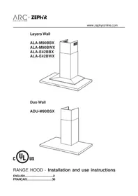
ALAM90BBX - Range hood Zephyr - Free user manual and instructions
Find the device manual for free ALAM90BBX Zephyr in PDF.


| Brand | Zephyr |
| Model | ALAM90BBX |
| Product type | Wall-mounted range hood |
| Width | 90 cm |
| Depth | 50 cm |
| Height | 60 cm (minimum 45 cm) |
| Weight | 15 kg |
| Power supply | 220-240 V ~ 50/60 Hz |
| Motor power | 250 W |
| Max air flow | 650 m³/h |
| Noise level | 42-65 dB(A) |
| Lighting | 2 x LED 3 W |
| Controls | Electronic buttons with timer |
| Speeds | 3 speeds + intensive |
| Filters | Washable metal grease filter (2 layers) |
| Charcoal filter | Optional, model ZE-FIL-01 |
| Evacuation type | Recirculation or extraction (duct Ø 150 mm) |
| Material | Brushed stainless steel |
| Maintenance | Clean filters monthly, glass with mild cleaner |
| Safety | Automatic shut-off, overheating protection |
| Included accessories | Mounting kit, diameter adapter, manual |
| Warranty | 2 years |
Frequently Asked Questions - ALAM90BBX Zephyr
User questions about ALAM90BBX Zephyr
0 question about this device. Answer the ones you know or ask your own.
Ask a new question about this device
Download the instructions for your Range hood in PDF format for free! Find your manual ALAM90BBX - Zephyr and take your electronic device back in hand. On this page are published all the documents necessary for the use of your device. ALAM90BBX by Zephyr.
USER MANUAL ALAM90BBX Zephyr
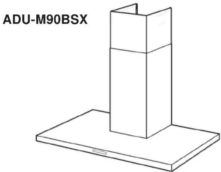
Duo Wall

RANGE HOOD - Installation and use instructions
ENGLISH....2
FRANÇAIS......30
Table of contents
Safety Instructions...... Page 3 - 4
List of Materials...... Page 5 - 6
Ducting Calculation Sheet...... Page 7
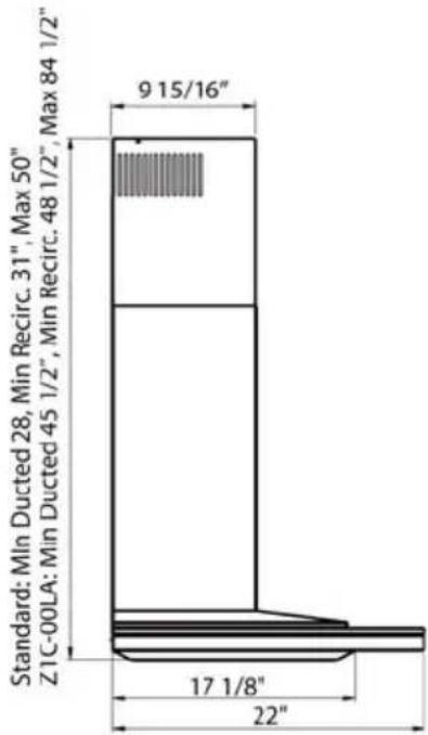
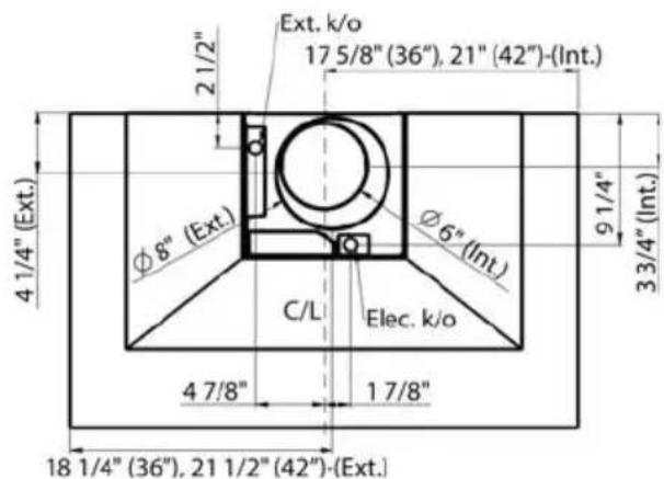
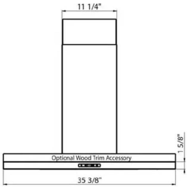
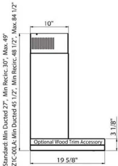
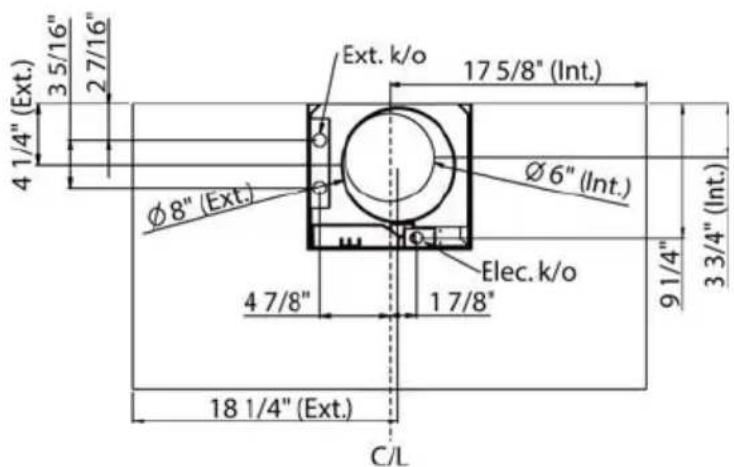
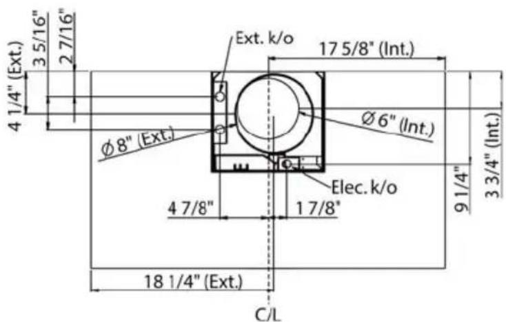
Hood Specifications......Page 8 - 9
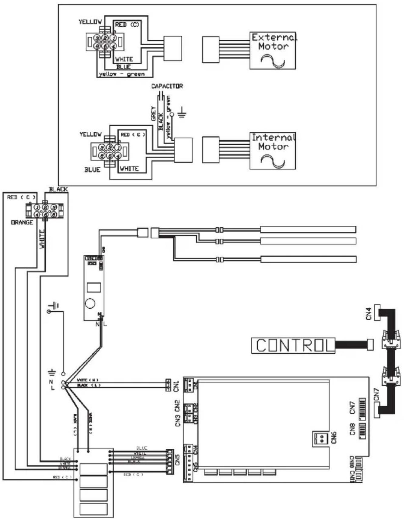
Wiring Diagram......Page 10
Cleaning and Maintenance......Page 11
Remote Control......Page 12
Hood Controls......Page 13 - 14
Installation
Internal Blower......Page 15 - 18
External and In-Line Blower......Page 19
Range Hood......Page 22
Duct Covers......Page 23 - 24
Non-Ducted Recirculation Kit......Page 25 - 26
Mesh Filters......Page 27
List of Parts & Accessories......Page 28
Warranty......Page 29
READ AND SAVE THESE INSTRUCTIONS
- Use this unit only in the manner intended by the manufacturer. If you have questions, contact the manufacturer at the address or telephone number listed in the warranty.
- Before servicing or cleaning unit, switch power off at service panel and lock service panel to prevent power from being switched on accidentally. When the service disconnecting means cannot be locked, securely fasten a prominent warning device, such as a tag, to the service panel.
- Installation work and electrical wiring must be done by a qualified person(s) in accordance with all applicable codes and standards, including fire-rated construction codes and standards.
- Sufficient air is needed for proper combustion and exhausting of gases through the flue (chimney) of fuel burning equipment to prevent backdrafting. Follow the heating equipment manufacturer's guidelines and safety standards such as those published by the National Fire Protection Association (NFPA), and the American Society for Heating, Refrigeration and Air Conditioning Engineers (ASHRAE), and the local code authorities.
- When cutting or drilling into wall or ceiling, do not damage electrical wiring and other hidden utilities.
- Ducted fans must always be vented to the outdoors.
- To reduce the risk of fire, use only steel ductwork.
GROUNDING INSTRUCTIONS
This appliance must be grounded. In the event of an electrical short circuit, grounding reduces the risk of electrical shock by providing an escape wire for the electric current.
WARNING - Improper grounding can result in a risk of electric shock.
Consult a qualified electrician if the grounding instructions are not completely understood, or if doubt exists as to whether the appliance is properly grounded.
TO REDUCE THE RISK OF A RANGE TOP GREASE FIRE:
- Never leave surface units unattended at high settings. Boilovers cause smoking and greasy spillovers that may ignite. Heat oils slowly on low or medium settings.
- Always turn hood ON when cooking at high heat or when flambeing food (i.e. Crepes Suzette, Cherries Jubilee, Peppercorn Beef Flambe').
- Clean ventilating fans frequently. Grease should not be allowed to accumulate on fan or filter.
- Use proper pan size. Always use cookware appropriate for the size of the surface element.
- Keep fan, filters and grease laden surface clean.
- Use high range setting on range only when necessary. Heat oil slowly on low to medium setting.
- Don't leave range unattended when cooking.
- Always use cookware and utensils appropriate for the type and amount of food being prepared.
TO REDUCE THE RISK OF INJURY TO PERSONS IN THE EVENT OF A RANGE TOP GREASE FIRE, OBSERVE THE FOLLOWING:*
- SMOTHER FLAMES with a close-fitting lid, cookie sheet, or metal tray, then turn off the burner. BE CAREFUL TO PREVENT BURNS. If the flames do not go out immediately, EVACUATE AND CALL THE FIRE DEPARTMENT.
- NEVER PICK UP A FLAMING PAN - You may be burned.
- DO NOT USE WATER, including wet dishcloths or towels - violent steam explosion will result.
- Use an extinguisher ONLY if:
A. You know you have a Class ABC extinguisher and you already know how to operate it.
B. The fire is small and contained in the area where it started.
C. The fire department is being called.
D. You can fight the fire with your back to an exit.
* Based on “Kitchen Fire Safety Tips” published by NFPA.

CAUTION
- For indoor use only.
- To reduce risk of fire and to properly exhaust air, be sure to duct air outside. Do not vent exhaust air into spaces within walls or ceilings or into attics, crawl spaces, or garages.
- Take care when using cleaning agents or detergents.
- Avoid using food products that produce flames under the Range Hood.
- For general ventilating use only. Do not use to exhaust hazardous or explosive materials and vapors.
- To avoid motor bearing damage and noisy and/or unbalanced impellers, keep drywall spray, construction dust, etc. off power unit.
- Your hood motor has a thermal overload which will automatically shut off the motor if it becomes overheated. The motor will restart when it cools down. If the motor continues to shut off and restart, have the hood serviced.
- For best capture of cooking impurities, the bottom of the hood should be no less than 24" above the cooking surface.
- Two installers are recommended because of the large size and weight of this hood.
- This product is equipped with a thermostat which may start blower automatically. To reduce the risk of injury and to prevent power from being switched on accidentally, switch power off at service panel and lock or tag service panel.
- Please read specification label on product for further information and requirements.
- To reduce risk of fire and electric shock, install this range hood only with Internal Blower Model CBI-290A or CBI-600A, Exterior Blower Model CBE-1000 or In-Line Blower Model PBN-1000A, (manufactured by Leyant Industry Co. Ltd). Other blowers cannot be substituted. (Blower sold separately)
Layers
- Zephyr blower sold separately
- Non-ducted recirculating kit sold separately
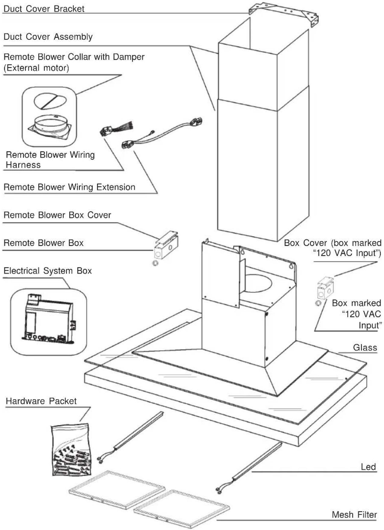
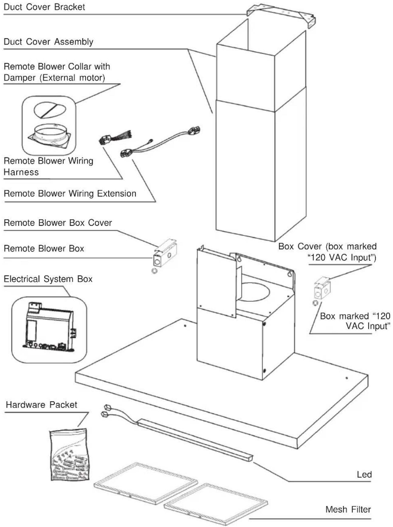
Duo
- Zephyr blower sold separately
- Non-ducted recirculating kit sold separately
| duct pieces | Equivalent number length x used = | Total | |
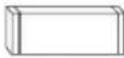 | 3-1/4" x 10" Rect., straight | 1 Ft. x ( ) = | Ft. |
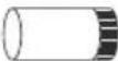 | 7" Round, straight | 1 Ft. x ( ) = | Ft. |
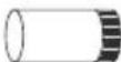 | 8" Round, straight | 1 Ft. x ( ) = | Ft. |
 | 3-1/4" x 10" Rect.90° elbow | 15 Ft. x ( ) = | Ft. |
 | 3-1/4" x 10" Rect.45° elbow | 9 Ft. x ( ) = | Ft. |
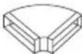 | 3-1/4" x 10" Rect.90° flat elbow | 24 Ft. x ( ) = | Ft. |
 | 3-1/4" x 10" Rect. wall cap with damper | 30 Ft. x ( ) = | Ft. |
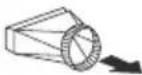 | 3-1/4" x 10" Rect.to 6" round transition | 5 Ft. x ( ) = | Ft. |
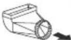 | 3-1/4" x 10" Rect.to 6" round transition 90° elbow | 20 Ft. x ( ) = | Ft. |
 | 6" Round, 90° elbow | 15 Ft. x ( ) = | Ft. |
 | 6" Round, 45° elbow | 9 Ft. x ( ) = | Ft. |
| Subtotal column 1 = | Ft. | ||
| duct pieces | Equivalent number length x used = | Total | |
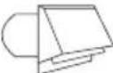 | 6"-8" Round wall cap with damper | 30 Ft. x( ) = | Ft. |
 | 6"-8" Round, roof cap | 30 Ft. x( ) = | Ft. |
 | 6" round to 3-1/4" x 10" rect. transition | 1 Ft. x( ) = | Ft. |
 | 6" round to 3-1/4" x 10" rect. transition 90° elbow | 16 Ft. x( ) = | Ft. |
 | 7" or 8" Round, 90° elbow | 15 Ft. x( ) = | Ft. |
 | 7" or 8" Round, 45° elbow | 9 Ft. x( ) = | Ft. |
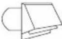 | 7" or 8" Round wall cap with damper | 30 Ft. x( ) = | Ft. |
 | 7" or 8" Round, roof cap | 30 Ft. x( ) = | Ft. |
 | 7" round to 3 1/4" x 10" rect. transition | 8 Ft. x( ) = | Ft. |
 | 7" round to 3-1/4" x 10" rect. transition 90° elbow | 23 Ft. x( ) = | Ft. |
| Subtotal column 2 = Subtotal column 1 = Total Ductwork = | Ft. | ||
| Ft. | |||
| Ft. | |||
Maximum Duct Length:
For satisfactory air movement, the total duct length should not exceed 100 equivalent feet.
Layers

Duo
![YELLOW RED (C) WHITE BLUE yellow - green External Motor CAPACITOR YELLOW RED (C) GREEN BLACK - green YELLOW RED (C) WHITE BLUE Internal Motor RED (C) ORANGE WHITE BLACK N L CONTROL CN4 WHITE (N) BLACK (L) CN1 CN3 CN2 CN5 CN6 CN7 CN7 BLUE WHITE LENG BLA-5 CN8 ON3 [000000] [000000] [000000] [000000] […](/content/2026/07/1522361/images/827767ec999163a82d3a66bde6c33cec816c916717bc4aaa0198076b79558dd9.jpg)
Proper maintenance of the Range Hood will assure proper performance of the unit.
Motor
The motor is permanently lubricated and never needs oiling. If the motor bearings make excessive or unusual noise, replace the motor with the exact service motor. The impeller should also be replaced.
Mesh Filters
The mesh filters should be cleaned frequently. Using warm water with detergent. Mesh filters are dishwasher safe.
Clean all-mesh filters in the dishwasher using a non-phosphate detergent. Discoloration of the filter may occur if using phosphate detergents, or as a result of local water conditions - but this will not affect filter performance. This discoloration is not covered by the warranty. See “MESH FILTERS” section for removal and installation instructions.
Non-ducted Charcoal Filter
The non-ducted charcoal filter should be changed every 6 months or when prompted on the hood controls. Replace more often if your cooking style generates extra grease, such as frying and wok cooking. See “MESH FILTERS” section for removal and installation instructions.
LED Lighting
In the unlikely event that your LED strip fails, please contact Zephyr to order replacement parts and schedule service.
Stainless Steel Cleaning
DO:
- Regularly wash with clean cloth or rag soaked with warm water and mild soap or liquid dish detergent.
• Always clean in the direction of original polish lines.
• Always rinse well with clear water (2 or 3 times) after cleaning. Wipe dry completely. - You may also use a specialized household stainless steel cleaner.
DON'T:
- Use any steel or stainless steel wool or any other scrapers to remove stubborn dirt.
- Use any harsh or abrasive cleansers.
- Allow dirt to accumulate.
- Let plaster dust or any other construction residues reach the hood. During construction/renovation, cover the range hood to make sure no dust sticks to the stainless steel surface.
Avoid: When choosing a detergent
- Any cleaners that contain bleach will attack stainless steel
- Any products containing: chloride, fluoride, iodide, bromide will deteriorate surfaces rapidly.
- Any combustible products used for cleaning such as acetone, alcohol, ether, benzol, etc., are highly explosive and should never be used close to a range.
SYNCHRONIZATION:
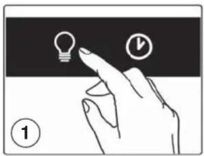
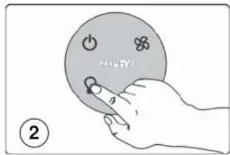
To synchronize the remote control with the range hood for the first time, proceed as follows:
- With range hood off, press and hold the "light" button on the range hood until the light indicator begins to flash (approximately 3 seconds) (Fig.1).
- Press the "light" button more times on the remote control until the lights on the hood turn on (Fig.2).
The range hood may now be activated using the remote control. If you experience any problems, repeat the procedure.
GENERAL INFORMATION:
- The remote control has a range of approximately 15 feet.
- The remote control is equipped with a magnetic base and may be attached to ferrous surface for easy storage.
- The remote top is made of a plastic material and is prone to scratches.
Use care when handling and cleaning the remote; we suggest using a microfiber cloth to clean it.
- The remote control will enter a sleep mode after 20 seconds of inactivity to conserve battery life. Press any button for one second to wake the remote.
BATTERY REPLACEMENT:
The batteries will last approximately 8 months, depending on usage.
- Remove rubber cover from bottom (Fig.3).
- Using an object such as a screwdriver or pen, gently place it in the center opening in the bottom of the remote and push inwards to dislodge the top touch panel from the remote body. (Fig. 4)
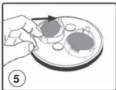
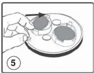
- Press on the metal spring located in the battery tray to dislodge battery. Replace both batteries with type 3V CR2450 (Fig.5). Re-assemble by following instructions in reverse.


CONTROLS
![graph TD A["Power"] --> B["Capacitor"] C["Drain"] --> D["Square Icon"] E["Load"] --> F["Light Bulb"] G["Ground"] --> H["Clock"] I["Input"] --> J["Clock Icon"] K["Output"] --> L["Clock Icon"] M["Input"] --> N["Clock Icon"] O["Output"] --> P["Clock Icon"]](/content/2026/07/1522361/images/9f65c254c9c9e6a667cd406dc19dc17db0921240edfdfb7d2ee931350f0977d9.jpg)
A: Power button
- Power Button will turn power on and off for the entire hood (fan and lights).
- Hood will remember the last speed and light level it was last turned off at.(Example: hood is turned off at when it was last on high speed and high lights; hood will turn back on at high speed and high lights when Power Button is pressed).
B: Fan Speed button
- From off, press once for low speed (1), twice for medium (2), and three times for high (3).
- Fan should cycle through speeds low (1), medium (2), and high (3) continuously.
C: Light button
- Lights are three level (high, medium, low).
- From off, touch once for high.
- From off, touch twice for medium.
- From off, touch three times for low.
- From off, touch four times to cycle back to off.
- Light level will cycle from high, medium, low, off.
D: Delay off button
- Press this button to enable the five minute delay-off function. After five minutes the fan and lights will power off.
- If the fan is already on (example high speed) the fan will change to low speed when the Delay Off Button is pressed and turn off after five minutes.
- When the Delay Off Function is on, the user can still change the fan speed by pressing the Fan Speed Button without interrupting the five minute Delay Off Timer.
- Delay Off Function can be turned off by pressing Delay Off Function button or Power Button.
G: Light indicator
- Light indicator will turn on when lights are turned on at any light level.
H: Filter clean and charcoal filter replace indicator
- Mesh filter clean (always enabled):
- Filter Clean Indicator will illuminate after 30 hours of fan usage indicating it is time to clean the mesh filter. Indicator light will remain illuminated, it will not blink.
- This function must be reset by the user. With hood off, hold the Fan Speed Button for five seconds, after five seconds the Filter Clean Indicator will turn off and the 30 hour timer will reset.
- Charcoal filter replace (disabled by default, must be enabled by user if recirculating hood):
- To enable Charcoal Filter Replacement Function:
- With hood off, hold Fan Speed and Delay Off buttons simultaneously for 5 seconds. Filter Clean Indicator will quickly flash 3 times indicating the Charcoal Filter Replacement Function is enabled. Filter Clean Indicator will continuously blink after 120 hours of unit
fan usage indicating it is time to replace the charcoal filter. Indicator light will blink, it will not remain illuminated.
- This function must be reset by the user. With hood off, hold the Delay Off Button for five seconds, after five seconds the Filter Clean Indicator will stop blinking and turn off and the 120 hour timer will reset.
Order replacement charcoal filter kit number Z0F-01AC through your local dealer, www.zephyronline.com or the Zephyr customer service department.
- To disable Charcoal Filter Replacement Function:
- With hood off, hold Fan Speed and Delay Off buttons simultaneously for 5 seconds. Filter Clean Indicator will illuminate for 3 second then turn off indicating the Charcoal Filter Replacement Function is disabled.
I: Delay off indicator
- Delay Off Indicator will light up when Delay Off Function is activated by pressing the
- Delay Off Button.
- Delay Off Indicator will turn off after the Delay Off Function has completed the five minute cycle or if the user presses the Delay Off Button again or the Power Button.
E: Clean air indicator
- Clean Air Indicator is disabled by default and must be enabled by the user.
- To enable Clean Air Function:
- With hood off, hold the Power Button down for five seconds. Clean Air Indicator light will illuminate, and the fan will turn on low speed for 10 minutes. After 10 minutes the fan will turn off and the 4 hour timer will begin. Clean Air Indicator will remain on when Clean Air Function is enabled, even if fan is not on. When Clean Air Function is enabled, every four hours of non fan usage the fan will automatically turn on at low speed for 10 minutes.
After 10 minutes the fan will turn off and the 4 hour timer will reset. When the Clean Air Function automatically turns the fan on the Clean Air Indicator will blink and the Low Speed fan indicator will illuminate. If the user changes the fan speed while the Clean Air Function is operating, the Clean Air Indicator will stop blinking but will remain illuminated. When the user manually turns the hood off the 4 hour timer will reset.
- To disable Clean Air Function:
- With hood off, hold Power Button down for five seconds until Clean Air Indicator light turns off.
Note1: Changing the fan speed and interrupting the Clean Air Function while it is operating does not disable the Clean Air Function. Clean Air Function will only be disabled by holding the Power Button for 5 seconds.
Note 2: Turning lights on/off does not disable the Clean Air Function.
F: Fan Speed indicator
- 1 = Low
- 2 = Medium
- 3 = High
- On speed low, only number 1 indicator will be on.
- On speed medium, 1 and 2 indicator will be on.
- On speed high, 1, 2 and 3 indicators will be on.
- When fan off, no fan speed indicator will be on.
LED LIGHT STRIP
If the LED is damaged, it must be replaced only by the manufacturer, its service agent or similarly qualified persons in order to avoid a hazard.
INSTALLING THE DUCTWORK: INTERNAL BLOWER
NOTE: To reduce the risk of fire, use only metal ductwork.
- Decide where the ductwork will run between the hood and the outside.
- A straight, short duct run using a minimum 6" round duct will allow the hood to perform most efficiently.
- Long duct runs, elbows, and transitions will reduce the performance of the hood. Use as few of them as possible.
- Install a roof or wall cap. Connect round metal ductwork to cap and work back towards hood location. Use duct tape to seal the joints between ductwork sections (Fig.7).
INSTALLING THE INTERNAL BLOWER
NOTE: The following instructions are for installing the internal blower only. Install this range hood only with internal blower model CBI-290A or CBI-600A.
- Remove the electrical system box from chimney frame by removing duct tape.
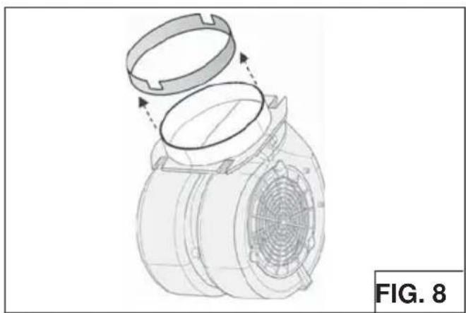
- Remove the 6" metallic flange provided on the blower's air outlet (the flange may already be pre-installed) (Fig.8).
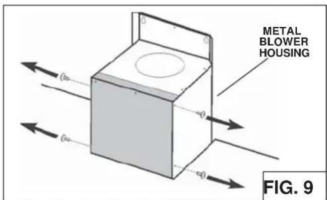
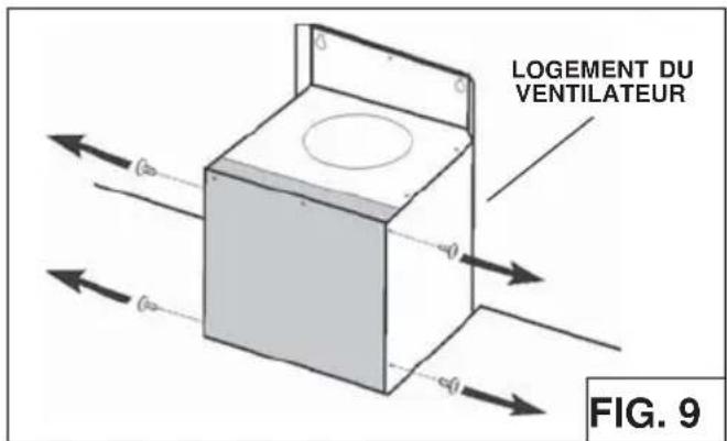
- Remove the front plate from the metal blower housing by unscrewing (4) 3.9x9.5 mm screws (Fig.9).
- Attach electrical system box to front plate using (2) 3.9 x 9.5 mm screws from

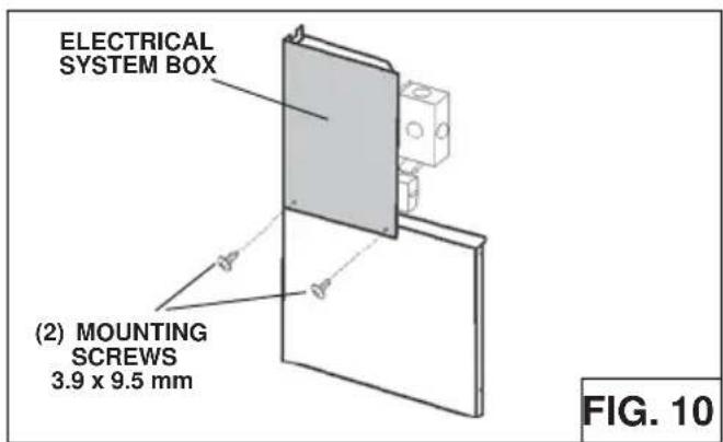
hardware bag (Fig.10).
- Remove the blower plate unscrewing the (4) 3.9x9.5 mm screws (Fig.11).

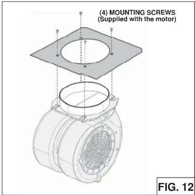
- Install internal blower into blower plate and secure using (4) screws (supplied with the internal blower) - See Fig.12.
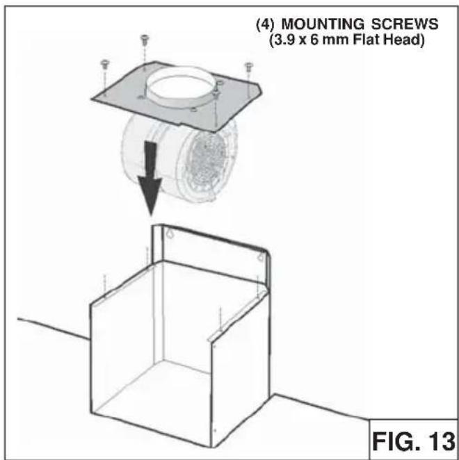
- Install blower using (4) 3,9 x 6mm mounting screws (Fig.13).
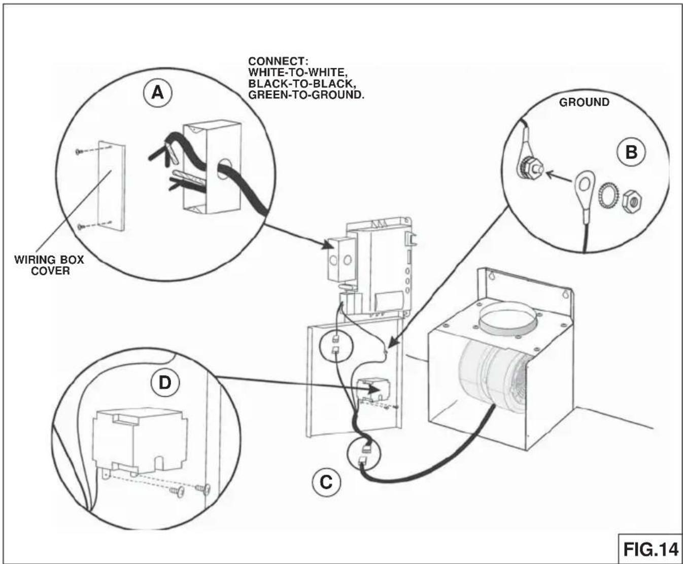
Note: This range hood must be properly grounded. The unit should be installed by a qualified electrician in accordance with all applicable national and local electrical codes.
- Make connections (A, B, C) (Fig.14).
- Secure capacitor box screwing the (2) 3.9x9.5 mm screws (Fig.14D).
- Remove the wiring box cover. Remove a knockout from the wiring box (Fig.14A).
- Secure the conduit to the wiring box through a conduit connector.
- Make electrical connections. Connect white to white, black to black and green to ground.
- Replace wiring box cover and screws. Make sure that wires are not pinched between cover and box.
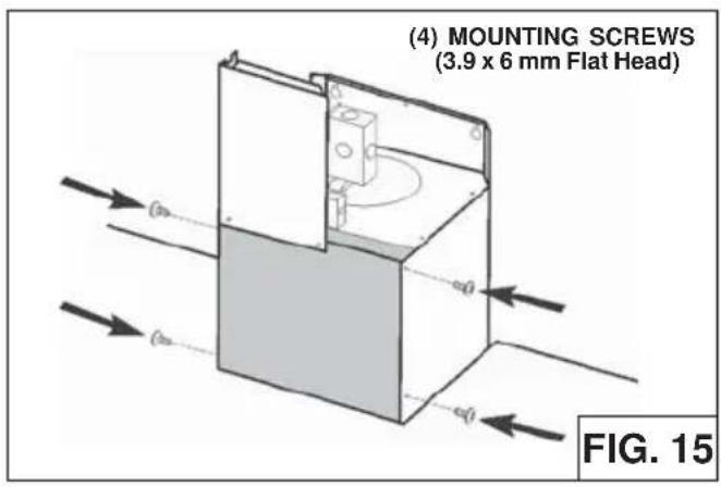
- Install the front plate and electrical system box using (4) 3.9x6 mm screws (Fig.15).
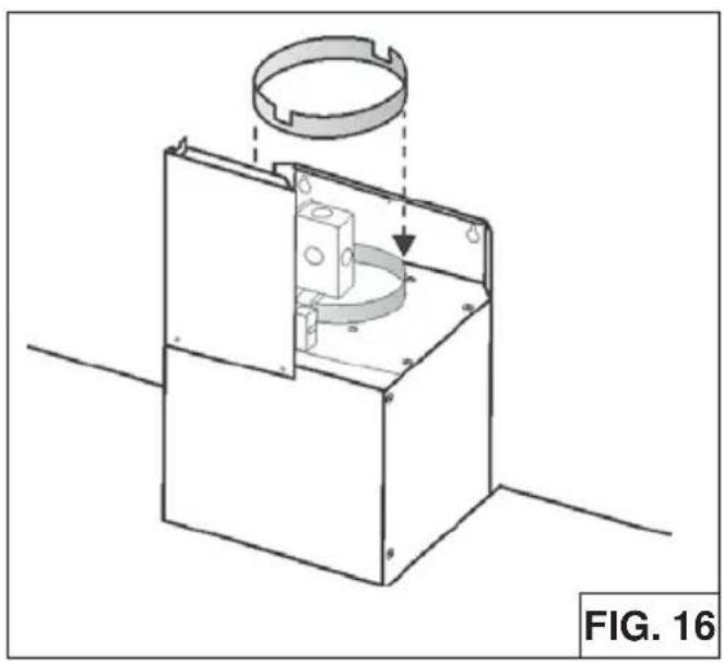
- Place the 6" metallic flange provided on the blower's air outlet (Fig.16).
REMOTE BLOWERS (EXTERNAL AND IN-LINE)
CAUTION: To reduce risk of fire and electric shock, install this range hood only with External Blower Model CBE-1000, and In-Line Blower Model PBN-1000A. Other blowers cannot be substituted.
INSTALLING THE DUCTWORK: REMOTE BLOWER
NOTE: To reduce the risk of fire, use only metal ductwork.
- Choose the location where the External Blower or In-Line Blower will be mounted. See illustrations below for mounting location suggestions and restrictions.
- A straight, short duct run using a minimum 8" round duct will allow the hood to perform most efficiently.
- Long duct runs, elbows and transitions will reduce the performance of the hood. Use as few of them as possible. Larger ducting may be required for best performance with long duct runs.
- After the External or In-Line Blower has been installed, connect round metal ductwork and work back towards the hood location. Use duct tape to seal joints between ductwork sections.
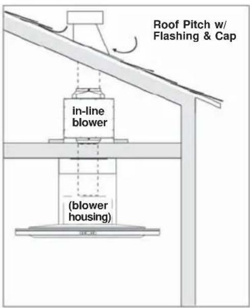

INSTALLING THE REMOTE BLOWER
NOTE: The following instructions are for preparing the hood for use with external or in-line blower models CBE-1000 or PBN-1000A. For blower installation details refer to manual included with the blower.
- Remove the electrical system box from chimney frame by removing duct tape.
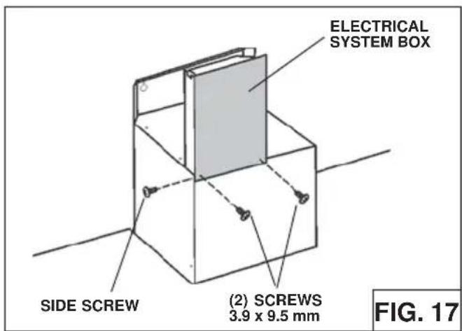
- Remove side screw (Fig.17) and mount electrical system box by means (2) 3,9x9,5 mm screws; re-fix the side screw.
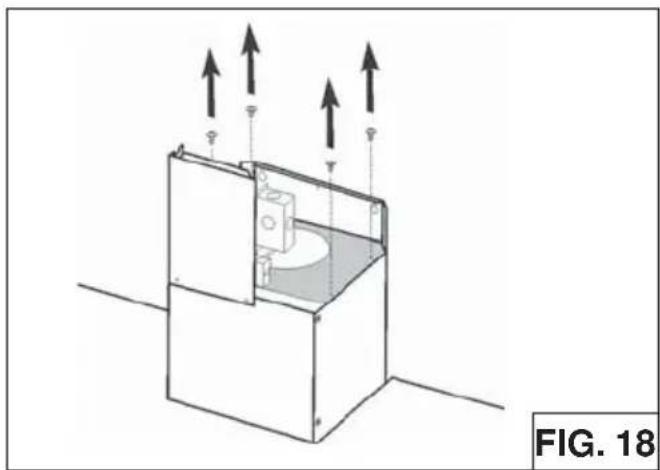
- Remove the blower plate unscrewing the (4) 3.9x6 mm screws (Fig.18).
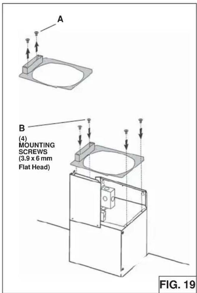
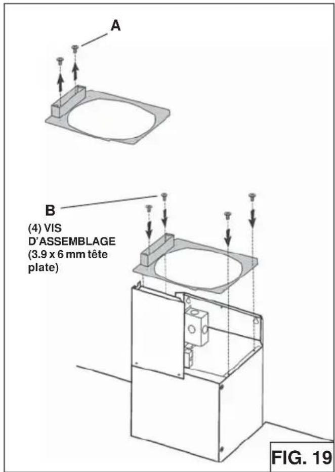
- Remove (2) screws (Fig.19A), position the external blower plate and remote blower box over blower housing and fix using (4) 3.9x6 mm screws (Fig.19B).
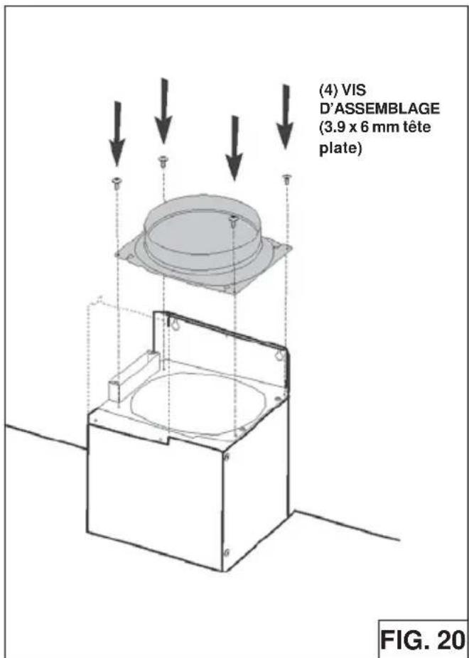
- Install 8" round blower collar to top of blower housing screwing the (4) 3.9x6 mm screws (Fig.20)

REMOTE BLOWER WIRING
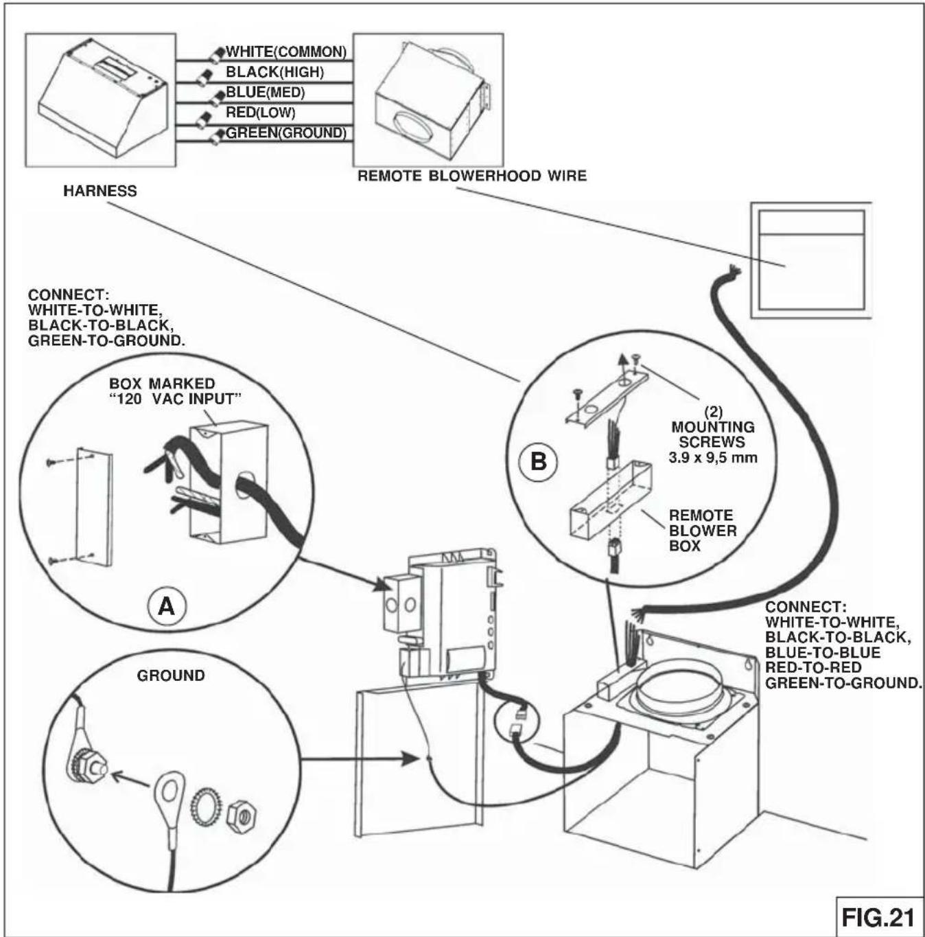
- Remove the cover from the wiring box marked "120 Vac input".
- Remove one knockout from the (2) wiring boxes (box marked "120 Vac input" and box marked "motor connection").
- Run 4-wire plus ground power cable from the remote blower to the remote blower wiring box marked "motor connection" (Fig.21B).
- Feed 6" of cable through the knockout opening and secure the cable to the wiring box with an appropriate connector.
- Make electrical connections at the hood (box marked 120 Vac input). Connect white-to-white, black-to-black, green-to-ground (Fig.21A).
- Make electrical connections (remote blower box marked "motor connection"). Connect white-to-white, black-to-black, blue-to-blue, red-to-red, green-to-ground (Fig.21B).
- Mount the wiring box covers and screws. Make sure wires are not pinched between the cover and box.
External blower connection:
- Make electrical connections at the remote blower (see instructions provided with the remote blower).
INSTALL THE HOOD
Remove the plastic protective film from all exterior surfaces, duct covers and filters, prior to final installation
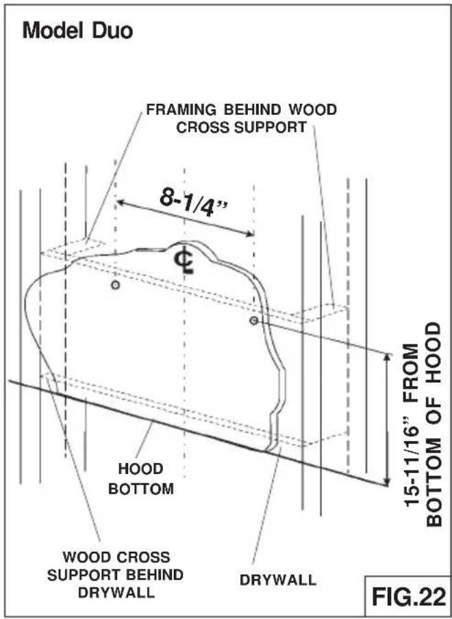
- Construct wood wall framing that is flush with interior surface of wall studs (Fig.22/23).
Make sure:
a) the framing is centered over installation location.
b) the height of the framing will allow the hood to be secured to the framing within the dimensions shown.
2. Determine desired height over cook top and mark hood bottom line. Install drywall anchors and 4,8x38mm screws per dimensions shown in Fig. 22/23.
3. Hang the hood onto the screws.
4. Tighten mounting screws. Add additional screws through hood body as needed for additional support.
Notes:
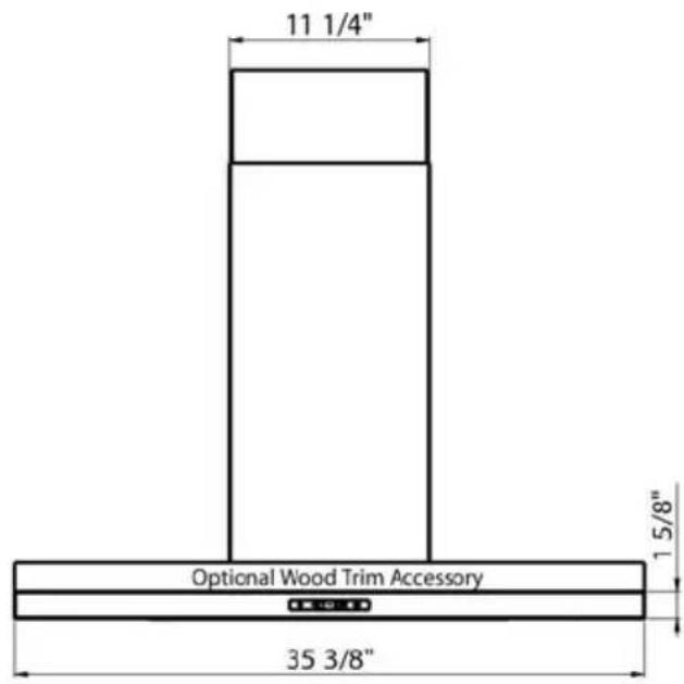
a. Minimum hood distance above cook top must not be less than 24". A maximum of 36" above cook top is highly recommended for best capture of cooking impurities. Distances over 36" are at the installer and the users discretion; and if ceiling height and flue lenght permit.

INSTALL DUCT COVER MOUNTING BRACKET
DUCTED AND NON-DUCTED
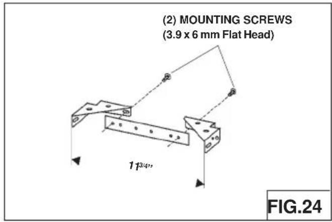
- Assemble the duct cover mounting bracket, adjusting outside width as shown. (Fig.24)
- Carefully center the mounting bracket directly over the range hood location.
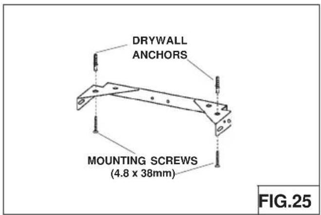
- Secure the bracket assembly to the ceiling using (2) 4.8 x 38mm mounting screws and drywall anchors (Fig.25). Make sure the bracket is pushed into the corner, tight against the wall if necessary, and centered over the hood.
DUCTED INSTALLATION ONLY
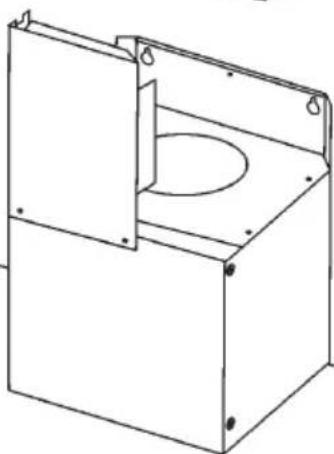
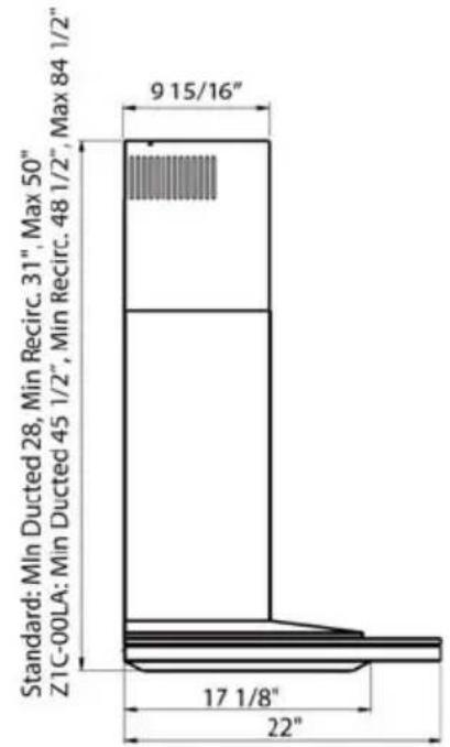
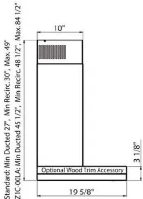
Note: Rooms with 10 to 12 foot ceiling require duct cover extension model Z1C-00LA, available from your local dealer. Discard the upper duct cover supplied with the range hood and replace it with the longer flue extension.
- Run 6-inch diameter metal ductwork to the outside location (Fig.26).
- Install an appropriate wall or roof cap with damper to exhaust the air to the outside.
- Tape all duct joints with aluminum duct tape.
- Install upper and lower duct covers onto the range hood (Fig.27).
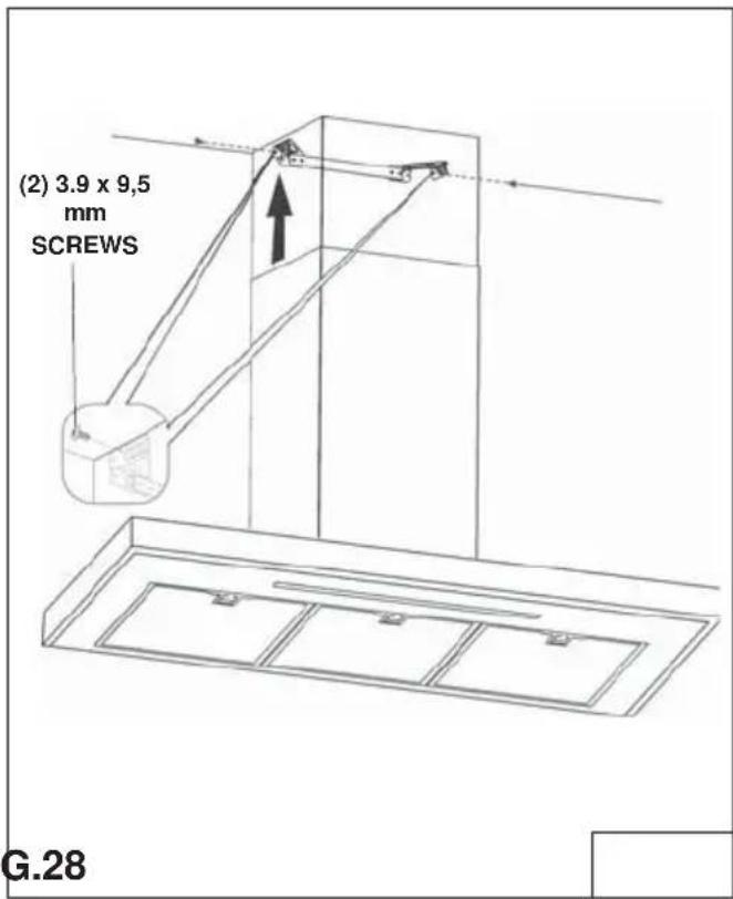
- Secure upper duct cover to duct cover mounting bracket with (2) 3.9 x 9,5 mm screws (Fig.28).


NON-DUCTED INSTALLATION ONLY
Note:
a. Purchase Model ZRC-01LA Non-ducted Recirculating Kit from your local dealer, sold separately.
b. Rooms with 10 to 12 foot ceilings require duct cover extension model Z1C-00LA, available from your local dealer. Discard the upper duct cover supplied with the range hood and replace it with the longer duct cover extension.
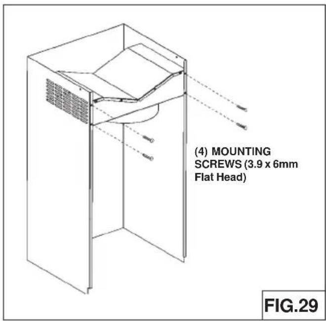
1. Install the plenum to the upper duct cover using (4) 3.9 x 6 mm screws provided as shown (Fig.29).
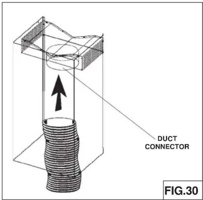
2. Install the 6" duct connector.
3. Attach 6-inch expandable ducting to the plenum and tape joint with aluminum duct tape (Fig.30).
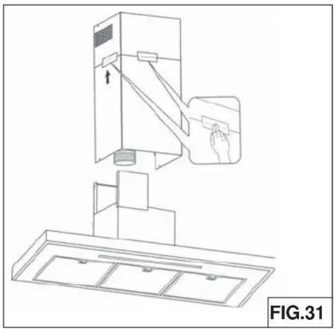
- Temporarily secure the upper and lower duct covers together with duct tape as shown (Fig.31).
- Lift the duct covers into position above the hood. Secure upper duct cover to the duct covers mounting bracket with (2) 3.9 x 9,5 mm screws (Fig.32).

- Remove tape from duct covers and lower into position on the hood (Fig.33).

MESH FILTERS
NOTE: prior to use, remove protective film from the filter frame.
DUCTED AND NON-DUCTED HOODS
- To remove the MESH filter, pull down on latch tab to disengage the filter from the hood. Tilt the filter downward and remove (Fig.34).
- To install the MESH filter, align rear filter tabs with slots in the hood. Pull latch tab down. Push filter into place and release tab. Make sure the filter is securely engaged after installation.
NON-DUCTED HOODS ONLY
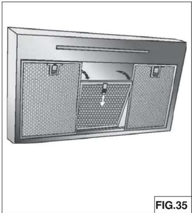
- To remove the CHARCOAL filter, grip and push filter tab toward rear of hood. Pull the filter down to disengage the rear filter tabs (Fig.35).
- To install the CHARCOAL filter, align filter in rectangular opening. Push filter against springs in rear of hood and press into place. Make sure the filter is securely engaged after assembly.
- Install MESH filter after charcoal filter is installed.
- The charcoal filter replacement model is ZOF-01AC.


| DESCRIPTION | HOOD | PART# |
| REPLACEMENT PARTS | ||
| Metal Mesh Filter ADU 50200031 | ||
| Metal Mesh Filter ALA 50200033 | ||
| OPTIONAL ACCESSORIES | ||
| Recirculating Kit ADU-ALA ZRC-01LA | ||
| Replacement Charcoal Filters ADU-ALA Z0F-01AC | ||
| Extension Flue up to 12' ADU-ALA Z1C-00LA |
To order parts, visit us online at http://store.zephyronline.com or call us at 1.888.880.8368
TO OBTAIN SERVICE UNDER WARRANTY OR FOR ANY SERVICE RELATED QUESTIONS, please call:
1-888-880-8368
Zephyr Ventilation, LLC (referred to herein as "we" or "us") warrants to the original consumer purchaser (referred to herein as "you" or "your") of Zephyr products (the "Products") that such Products will be free from defects in materials or workmanship as follows:
One Year Limited Warranty for Parts: For one year from the date of your original purchase of the Products, we will provide, free of charge. Products or parts (including LED light bulbs, if applicable) to replace those that failed due to manufacturing defects. We may choose, in our sole discretion, to repair or replace parts before we elect to replace the Products.
One Year Limited Warranty for Labor: For one year from the date of your original purchase of the Products, we will provide free of charge, the labor cost associated with repairing the Products or parts to replace those that failed due to manufacturing defects. After the first year from the date of your original purchase, you are responsible for all labor costs associated with this warranty.
Warranty Exclusions: This warranty covers only repair or replacement, at our option, of defective Products or parts and does not cover any other costs related to the Products including but not limited to: (a) normal maintenance and service required for the Products and consumable parts such as fluorescent, incandescent or halogen light bulbs, mesh and charcoal filters and fuses; (b) any Products or parts which have been subject to freight damage, misuse, negligence, accident, faulty installation or installation contrary to recommended installation instructions, improper maintenance or repair (other than by us); (c) commercial use of the Products or use otherwise inconsistent with its intended purpose; (d) natural wear of the finish of the Products or wear caused by improper maintenance, use of corrosive and abrasive cleaning products, pads, and oven cleaner products; (e) chips, dents or cracks caused by abuse or misuse of the Products; (f) service trips to your home to teach you how to use the Products; (g) damage to the Products caused by accident, fire, floods, acts of God; or (h) Custom installations or alterations that impact serviceability of the Products. If you are outside our service area, additional charges may apply for shipping costs for warranty repair at our designated service locations and for the travel cost to have a service technician come to your home to repair, remove or reinstall the Products. After the first year from the date of your original purchase, you are also responsible for all labor costs associated with this warranty.
Limitations of Warranty. OUR OBLIGATION TO REPAIR OR REPLACE, AT OUR OPTION, SHALL BE YOUR SOLE AND EXCLUSIVE REMEDY UNDER THIS WARRANTY. WE SHALL NOT BE LIABLE FOR INCIDENTAL, CONSEQUENTIAL OR SPECIAL DAMAGES ARISING OUT OF OR IN CONNECTION WITH THE USE OR PERFORMANCE OF THE PRODUCTS. THE EXPRESS WARRANTIES IN THE PRECEDING SECTION ARE EXCLUSIVE AND IN LIEU OF ALL OTHER EXPRESS WARRANTIES. WE HEREBY DISCLAIM AND EXCLUDE ALL OTHER EXPRESS WARRANTIES FOR THE PRODUCTS, AND DISCLAIM AND EXCLUDE ALL WARRANTIES IMPLIED BY LAW, INCLUDING THOSE OF MERCHANTABILITY AND FITNESS FOR A PARTICULAR PURPOSE. Some states or provinces do not allow limitations on the duration of an implied warranty or the exclusion or limitation of incidental or consequential damages, so the above limitations or exclusions may not apply to you. To the extent that applicable law prohibits the exclusion of implied warranties, the duration of any applicable implied warranty is limited to the same one-year period described above. Any oral or written description of the Products is for the sole purpose of identifying the Products and shall not be construed as an express warranty. Prior to using, implementing or permitting use of the Products, you shall determine the suitability of the Products for the intended use, and you shall assume all risk and liability whatsoever in connection with such determination. We reserve the right to use functionally equivalent refurbished or reconditioned parts or Products as warranty replacements or as part of warranty service. This warranty is not transferable from the original purchaser and applies in the United States and Canada.
To Obtain Service Under Limited Warranty: To qualify for warranty service, you must: (a) notify us at the address or telephone number stated below within 60 days of the discovery of the defect; (b) give the model number and part identification number and serial number; and (c) describe the nature of any defect in the Product or part. At the time of the request for warranty service, you must present evidence of your proof of purchase and proof of the original purchase date. If we determine that the warranty exclusions listed above apply or if you fail to provide the necessary documentation to obtain service, you will be responsible for all shipping, travel, labor and other costs related to the services.
Please check our website for any revisions, www.zephyronline.com.
Zephyr Ventilation Service Department, 2277 Harbor Bay Parkway, Alameda, CA 94502 1-888-880-8368
AUG14.0201
Layers Wall
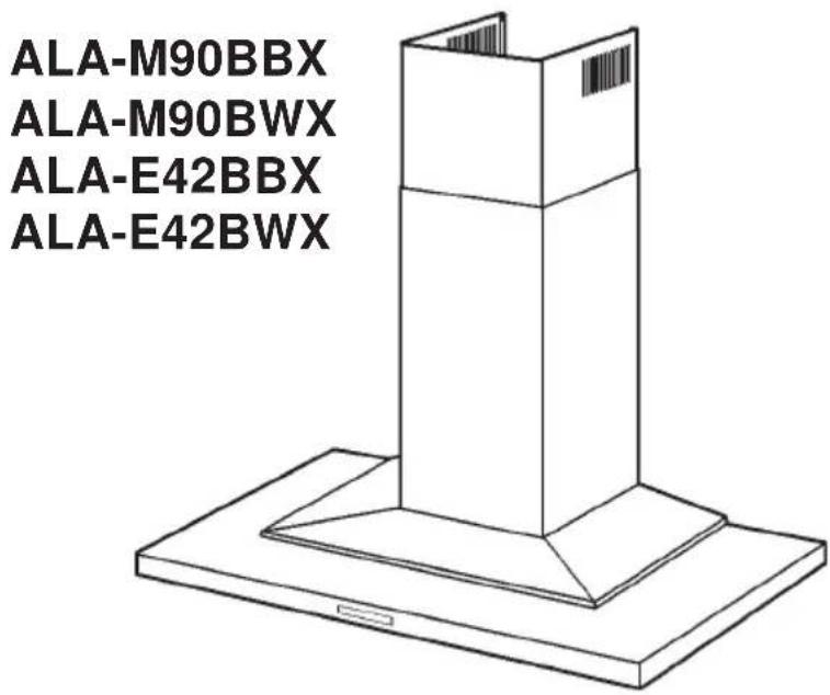
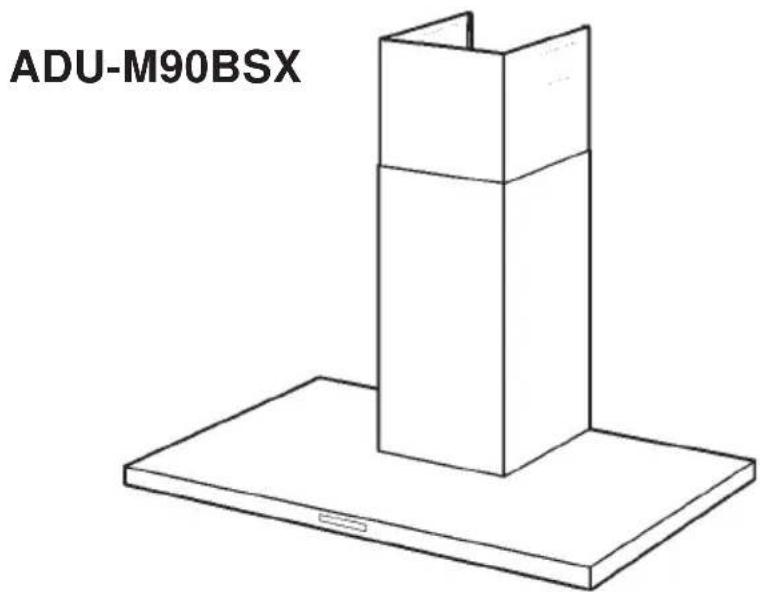
Duo Wall
Sommaire
Accessoire de fixation
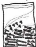

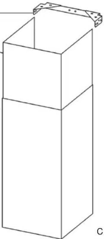
Accessoire de fixation


| Elément du conduit | Numéro équivalent longueur pour tronçons utilisés | Total | |
| 3-1/4" x 10" Rect., straight | 1 Ft. x( ) = | Ft. | |
| 7" Round, straight | 1 Ft. x( ) = | Ft. | |
| 8" Round, straight | 1 Ft. x( ) = | Ft. | |
| 3-1/4" x 10" Rect.90° elbow | 15 Ft. x( ) = | Ft. | |
| 3-1/4" x 10" Rect.45° elbow | 9 Ft. x( ) = | Ft. | |
| 3-1/4" x 10" Rect.90° flat elbow | 24 Ft. x( ) = | Ft. | |
| 3-1/4" x 10" Rect. wall cap with damper | 30 Ft. x( ) = | Ft. | |
| 3-1/4" x 10" Rect. to 6" round transition | 5 Ft. x( ) = | Ft. | |
| 3-1/4" x 10" Rect. to 6" round transition 90° elbow | 20 Ft. x( ) = | Ft. | |
| 6" Round, 90° elbow | 15 Ft. x( ) = | Ft. | |
| 6" Round, 45° elbow | 9 Ft. x( ) = | Ft. | |
| Total partiel colonne n°1 = | Ft. | ||
| Elément du conduit | Numéro équivalent longueur pour tronçons utilisés | Total | |
| 6"-8" Round wall cap with damper | 30 Ft. x( ) = | Ft. | |
| 6"-8" Round, roof cap | 30 Ft. x( ) = | Ft. | |
| 6" round to 3-1/4" x 10" rect. transition | 1 Ft. x( ) = | Ft. | |
| 6" round to 3-1/4" x 10" rect. transition 90° elbow | 16 Ft. x( ) = | Ft. | |
| 7" or 8" Round, 90° elbow | 15 Ft. x( ) = | Ft. | |
| 7" or 8" Round, 45° elbow | 9 Ft. x( ) = | Ft. | |
| 7" or 8" Round wall cap with damper | 30 Ft. x( ) = | Ft. | |
| 7" or 8" Round, roof cap | 30 Ft. x( ) = | Ft. | |
| 7" round to 3 1/4" x 10" rect. transition | 8 Ft. x( ) = | Ft. | |
| 7" round to 3-1/4" x 10" rect. transition 90° elbow | 23 Ft. x( ) = | Ft. | |
| Total partiel colonne n°2 = Total partiel colonne n°1 = Total conduit = | Ft. | ||
| Ft. | |||
| Ft. | |||

Duo
REEMPLACEMENT DES PILES:

FONCTION DES TOUCHES
![graph TD A["Power"] --> 1 B["Discharge"] --> 1 1 --> 2 2 --> 3 3 --> 4 4 --> 5 5 --> C 6 --> D 7 --> D](/content/2026/07/1522361/images/93d869b3c301ce935ad08131c7e6371bc3c57e2195875422561262756adf430e.jpg)
A: Touche Power

VENTILATEUR EXTERNE (EXTERIEUR OU "IN-LINE")
INSTALLATION ELECTRIQUE VENTILATEUR EXTERNE
Zephyr Ventilation Service Department, 2277 Harbor Bay Parkway, Alameda, CA 94502 1-888-880-8368
AUG14.0401
PRODUCT REGISTRATION
Congratulations on your Zephyr range hood purchase! Please take a moment to register your new range hood at www.zephyronline.com/registration
IT'S IMPORTANT
Prompt registration helps in more ways than one.
- Ensures warranty coverage should you need service.
- Ownership verification for insurance purposes.
- Notification of product changes or recalls.

Zephyr Ventilation | 2277 Harbor Bay Pkwy. | Alameda, CA 94502 | 1.888.880.8368


- TABLE OF CONTENTS
- INSTALLATION
- READ AND SAVE THESE INSTRUCTIONS
- GROUNDING INSTRUCTIONS
- TO REDUCE THE RISK OF A RANGE TOP GREASE FIRE
- TO REDUCE THE RISK OF INJURY TO PERSONS IN THE EVENT OF A RANGE TOP GREASE FIRE, OBSERVE THE FOLLOWING
- CAUTION
- LAYERS
- DUO
- MAXIMUM DUCT LENGTH
- MOTOR
- MESH FILTERS
- NON-DUCTED CHARCOAL FILTER
- LED LIGHTING
- STAINLESS STEEL CLEANING
- DO
- DON'T
- AVOID: WHEN CHOOSING A DETERGENT
- SYNCHRONIZATION
- GENERAL INFORMATION
- BATTERY REPLACEMENT
- CONTROLS
- A: POWER BUTTON
- B: FAN SPEED BUTTON
- C: LIGHT BUTTON
- D: DELAY OFF BUTTON
- G: LIGHT INDICATOR
- H: FILTER CLEAN AND CHARCOAL FILTER REPLACE INDICATOR
- I: DELAY OFF INDICATOR
- E: CLEAN AIR INDICATOR
- F: FAN SPEED INDICATOR
- LED LIGHT STRIP
- INSTALLING THE DUCTWORK: INTERNAL BLOWER
- INSTALLING THE INTERNAL BLOWER
- REMOTE BLOWERS (EXTERNAL AND IN-LINE)
- INSTALLING THE DUCTWORK: REMOTE BLOWER
- NOTE: TO REDUCE THE RISK OF FIRE, USE ONLY METAL DUCTWORK
- INSTALLING THE REMOTE BLOWER
- REMOTE BLOWER WIRING
- EXTERNAL BLOWER CONNECTION
- INSTALL THE HOOD
- REMOVE THE PLASTIC PROTECTIVE FILM FROM ALL EXTERIOR SURFACES, DUCT COVERS AND FILTERS, PRIOR TO FINAL INSTALLATION
- NOTES
- INSTALL DUCT COVER MOUNTING BRACKET
- DUCTED AND NON-DUCTED
- DUCTED INSTALLATION ONLY
- NON-DUCTED INSTALLATION ONLY
- NOTE
- DUCTED AND NON-DUCTED HOODS
- NON-DUCTED HOODS ONLY
- SOMMAIRE
- REEMPLACEMENT DES PILES
- FONCTION DES TOUCHES
- A: TOUCHE POWER
- VENTILATEUR EXTERNE (EXTERIEUR OU "IN-LINE")
- INSTALLATION ELECTRIQUE VENTILATEUR EXTERNE
- PRODUCT REGISTRATION
- IT'S IMPORTANT
Brand : Zephyr
Model : ALAM90BBX
Category : Range hood