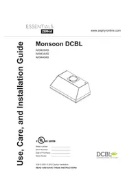
AK9428AS - Range hood Zephyr - Free user manual and instructions
Find the device manual for free AK9428AS Zephyr in PDF.


| Product type | Range hood |
| Brand | Zephyr |
| Model | AK9428AS |
| Dimensions (W x D x H) | 90 x 50 x 60 cm |
| Net weight | 15 kg |
| Power supply | 220-240 V, 50 Hz |
| Motor power | 250 W |
| Lighting | LED, 2 x 3 W |
| Number of speeds | 3 |
| Maximum noise level | 65 dB |
| Filter type | Washable metal grease filter |
| Exhaust duct diameter | 150 mm |
| Recirculation mode | Possible with carbon filter (optional) |
| Controls | Electronic push buttons |
| Material | Stainless steel |
| Energy class | A |
| Estimated annual consumption | 50 kWh |
| Maintenance | Clean grease filters every month |
| Safety | Automatic safety shut-off |
| Warranty | 2 years |
Frequently Asked Questions - AK9428AS Zephyr
User questions about AK9428AS Zephyr
0 question about this device. Answer the ones you know or ask your own.
Ask a new question about this device
Download the instructions for your Range hood in PDF format for free! Find your manual AK9428AS - Zephyr and take your electronic device back in hand. On this page are published all the documents necessary for the use of your device. AK9428AS by Zephyr.
USER MANUAL AK9428AS Zephyr

Model number: ____
Serial Number: ____
Date of Purchase: ____
Sales Dealer: ____
SAFETY NOTICE 2-3
LIST OF MATERIALS 4
INSTALLATION
Ducting Calculation Sheet 5
Mounting Height & Clearance 6
Ducting Options 7
Specifications 8
Electrical 9
Cabinet Preparation & Installation 10
Vertical Ducting Preparation.... 11
Horizontal Ducting Preparation 12-14
FEATURES & CONTROLS
Touch Controls 15
User Interface.... 16
RF Remote Control 17
MAINTENANCE
Cleaning and Installing Filters 18
TROUBLESHOOTING 19
FAN CURVE & WIRING DIAGRAMS 20
LIST OF PARTS AND ACCESSORIES 21
WARNING
TO REDUCE THE RISK OF FIRE OR ELECTRIC SHOCK, DO NOT USE THIS FAN WITH ANY SOLID-STATE CONTROL DEVICE.
WARNING
TO REDUCE THE RISK OF FIRE ELECTRIC SHOCK, OR INJURY TO PERSONS, OBSERVE THE FOLLOWING:
a. Use this unit only in the manner intended by the manufacturer, if you have questions, contact the manufacturer.
b. Before servicing or cleaning unit, switch power off at service panel and lock panel to prevent power from being switched on accidentally. When the service disconnecting means cannot be locked, securely fasten a prominent warning device, such as a tag, to the service panel.
CAUTION
For general ventilating use only. Do not use to exhaust hazardous or explosive materials and vapors. Take care when using cleaning agents or detergents. Suitable for use in household cooking area.
WARNING
TO REDUCE THE RISK OF RANGE TOP GREASE FIRE:
a. Never leave surface units unattended at high settings. Boilovers cause smoking and greasy spillovers that may ignite. Heat oils slowly on low or medium settings.
b. Always turn hood ON when cooking at high heat or when flaming food
c. Clean ventilating fans frequently. Grease should not be allowed to accumulate on fan or filter.
d. Use proper pan size. Always use cookware appropriate for the size of the surface element.
e. Keep fan, filters and grease laden surfaces clean.
f. Use high setting on hood only when necessary.
g. Don't leave hood unattended when cooking.
h. Always use cookware and utensils appropriate for the type of and amount of food being prepared.
WARNING
TO REDUCE THE RISK OF INJURY TO PERSONS IN THE EVENT OF A RANGE TOP FIRE, OBSERVE THE FOLLOWING:
a. SMOTHER FLAMES with a close-fitting lid, cookie sheet, or metal tray, then turn off the burner. BE CAREFUL TO PREVENT BURNS. If the flames do not go out immediately, EVACUATE AND CALL THE FIRE DEPARTMENT.
b. NEVER PICK UP A FLAMING PAN – You may be burned.
c. DO NOT USE WATER, including wet dishcloths or towels – a violent steam explosion will result.
d. Use an extinguisher ONLY if:
- You know you have a Class ABC extinguisher, and you already know how to operate it.
- The fire is small and contained in the area where it started.
- The fire department is being called.
- You can fight the fi re with your back to an exit
WARNING
TO REDUCE THE RISK OF FIRE, ELECTRIC SHOCK OR INJURY TO PERSONS, OBSERVE THE FOLLOWING:
a. Installation work and electrical wiring must be done by qualified person(s) in accordance with all applicable codes and standards. Including fi re-rated construction.
b. Sufficient air is needed for power combustion and exhausting of gases through the flue (chimney) of fuel burning equipment to prevent back-drafting. Follow the heating equipment manufacturer's guideline and safety standards such as those published by the National Fire Protection Association (NFPA) and the American Society for Heating, Refrigeration and Air Conditioning Engineers (ASHRAE) and the local code authorities.
c. When cutting or drilling into wall or ceiling, do not damage electrical wiring and other hidden utilities.
d. Ducted fans must always vent to the outdoors.
e. NEVER place a switch where it can be reached from a tub or shower.
f. Make sure the power is off before installing, wiring or maintaining.
WARNING
TO REDUCE THE RISK OF FIRE, USE ONLY METAL DUCTWORK.
NOT FOR USE OVER AN OUTDOOR GRILL
CAUTION
To reduce risk of fi re and to properly exhaust air outside - Do not vent exhaust air into spaces within walls, ceilings, attics, crawl spaces or garages.
OPERATION
Always leave safety grilles and filters in place. Without these components, operating blowers could catch onto hair, fingers and loose clothing.
The manufacturer declines all responsibility in the event of failure to observe the instructions given here for installation, maintenance and suitable use of the product. The manufacturer further declines all responsibility for injury due to negligence and the warranty of the unit automatically expires due to improper maintenance.
*NOTE: Please check www.zephyronline.com for revisions before doing any custom work.
ELECTRICAL REQUIREMENTS
Important:
Observe all governing codes and ordinances.
It is the customer's responsibility:
- To contact a qualified electrical installer.
- To assure that the electrical installation is adequate and in conformance with National Electrical Code, ANSI/NFPA 70 latest edition* or CSA standards C22.1-94, Canadian Electrical Code, Part 1 and C22.2 No.0-M91 - latest edition** and all local codes and ordinances.
If codes permit and a separate ground wire is used, it is recommended that a qualified electrician determine that the ground path is adequate.
Do not ground to a gas pipe.
Check with a qualified electrician if you are not sure the range hood is properly grounded.
Do not have a fuse in the neutral or ground circuit.
*National Fire Protection Association Batterymarch Park, Quincy, Massachusetts 02269
** CSA International 8501 East Pleasant Valley Road, Cleveland, Ohio 44131-5575
This appliance requires a 120V 60Hz electrical supply and connected to an individual properly grounded branch circuit protected by a 15 or 20 ampere circuit breaker or time delay fuse. Wiring must be 2 wire with ground. Please also refer to Electrical Diagram on product.
AK9428AS / AK9434AS - Max. 219W, 3.5 Amps
AK9440AS - Max. 225W, 3.6 Amps
A cable locking connector (not supplied) might also be required by local codes. Check with local requirements, purchase and install appropriate connector if necessary.
FEDERAL COMMUNICATION COMMISSION INTERFACE STATEMENT
This equipment has been tested and found to comply with the limits for a Class B digital device, pursuant to Part 15 of the FCC Rules. These limits are designed to provide reasonable protection against harmful interference in a residential installation.
This equipment generates, uses and can radiate radio frequency energy and, if not installed and used in accordance with the instructions, may cause harmful interference to radio communications. However, there is no guarantee that interference will not occur in a particular installation. If this equipment does cause harmful interference to radio or television reception, which can be determined by turning the equipment off and on, the user is encouraged to try to correct the interference by one of the following measures:
. Reorient or relocate the receiving antenna.
. Increase the separation between the equipment and receiver.
. Connect the equipment into an outlet on a circuit different from that to which the receiver is connected.
. Consult the dealer or an experienced radio/TV technician for help
MODELS: AK9428AS, AK9434AS AND AK9440AS
PARTS SUPPLIED
1 - Liner hood body
3 - Baffl e fi Iters
2 - 6W Zephyr Bloom™ LED light bulbs (pre-installed) (3 for AK9440AS)
1 - Internal blower (pre-installed)
1 - 8" round adaptor w/damper
1 - 3 1/4" x 10" rectangular adaptor w/damper
2 - Horizontal ducting blower mount brackets
1 - Top rectangular cover plate
1 - Hardware package
HARDWARE PACKAGE CONTENTS


PARTS NOT SUPPLIED
- Ducting, conduit and all installation tools
- Cable connector (if required by local codes)
| Duct pieces | Equivalent number length x used = | Total | |
 | 3-1/4" x 10" Rect., straight | 1 Ft. x ( ) = | Ft. |
 | 6" Round, straight | 1 Ft. x ( ) = | Ft. |
 | 7"-10" Round, straight | 1 Ft. x ( ) = | Ft. |
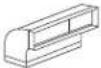 | 3-1/4" x 10" Rect.90° elbow | 15 Ft. x ( ) = | Ft. |
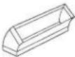 | 3-1/4" x 10" Rect.45° elbow | 9 Ft. x ( ) = | Ft. |
 | 3-1/4" x 10" Rect.90° flat elbow | 24 Ft. x ( ) = | Ft. |
 | 3-1/4" x 10" Rect. wall cap with damper | 30 Ft. x ( ) = | Ft. |
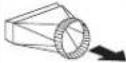 | 3-1/4" x 10" Rect.to 6" round transition | 5 Ft. x ( ) = | Ft. |
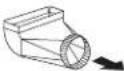 | 3-1/4" x 10" Rect.to 6" round transition 90° elbow | 20 Ft. x ( ) = | Ft. |
 | 6" Round, 90° elbow | 15 Ft. x ( ) = | Ft. |
 | 6" Round, 45° elbow | 9 Ft. x ( ) = | Ft. |
| Subtotal column 1 = | Ft. | ||
| Duct pieces | Equivalent number length x used = | Total | |
| 6" Round wall cap with damper | 30 Ft. x ( ) = | Ft. | |
| 6" Round, roof cap | 30 Ft. x ( ) = | Ft. | |
| 6" round to 3-1/4" x 10" rect. transition | 1 Ft. x ( ) = | Ft. | |
| 6" round to 3-1/4" x 10" rect. transition 90° elbow | 16 Ft. x ( ) = | Ft. | |
| 7" - 10" Round, 90° elbow | 15 Ft. x ( ) = | Ft. | |
| 7" - 10" Round, 45° elbow | 9 Ft. x ( ) = | Ft. | |
| 7" - 10" Round wall cap with damper | 30 Ft. x ( ) = | Ft. | |
| 7" - 10" Round, roof cap | 30 Ft. x ( ) = | Ft. | |
| 7" round to 3 1/4" x 10" rect. transition | 8 Ft. x ( ) = | Ft. | |
| 7" round to 3-1/4" x 10" rect. transition 90° elbow | 23 Ft. x ( ) = | Ft. | |
| Subtotal column 2 = Subtotal column 1 = Total ductwork = | Ft. | ||
| Ft. | |||
| Ft. | |||
Maximum Duct Length: For satisfactory air movement, the total duct length should not exceed 100 equivalent feet.
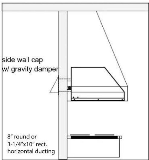
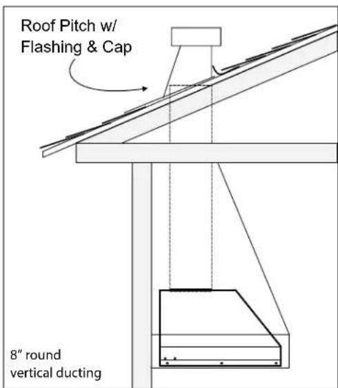
DUCTING
A minimum of 8" round or 3-1/4" x 10" rectangular duct must be used to maintain maximum air flow efficiency.
Always use rigid type metal ducts only. Flexible ducts could restrict air flow by up to 50%.
Also use calculation (on page 5) to compute total available duct run when using elbows, transitions and caps.
ALWAYS, when possible, reduce the number or transitions and turns. If long duct run is required, increase duct size.
If turns or transitions are required; install as far away from hood duct output and as far apart, between the two as possible.
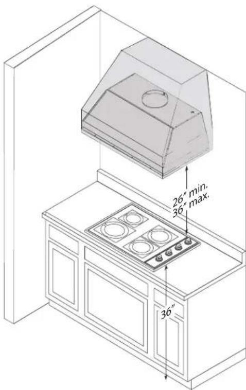
Minimum mount height between range top to hood bottom should be no less than 26".
Maximum mount height should be no higher than 36".
It is important to install the hood at the proper mounting height. Hoods mounted too low could result in heat damage and fi re hazard; while hoods mounted too high will be hard to reach and will lose its performance and effi ciency.
If available, also refer range manufacturer's height clearance requirements and recommended hood mounting height above range.
Vertical Ducting:
8" round minimum
Horizontal Ducting:
8" round or 3 1/4" x 10" rectangular minimum
DAMAGE-SHIPMENT / INSTALLATION:
- Please fully inspect unit for damage before installation.
- If the unit is damaged in shipment, return the unit to the store in which it was bought for repair or replacement.
- If the unit is damaged by the customer, repair or replacement is the responsibility of the customer.
- If the unit is damaged by the installer (if other than the customer), repair of replacement must be made by arrangement between customer and installer.
WARNING FIRE HAZARD
NEVER exhaust air or terminate duct work into spaces between walls, crawl spaces, ceiling, attics or garages. All exhaust must be ducted to the outside.
Use single wall rigid metal ductwork only.
Fasten all connections with sheet metal screws and tape all joints with certified Silver Tape or Duct Tape.
Some Ducting Options

Installation – Specifications

3/4 View
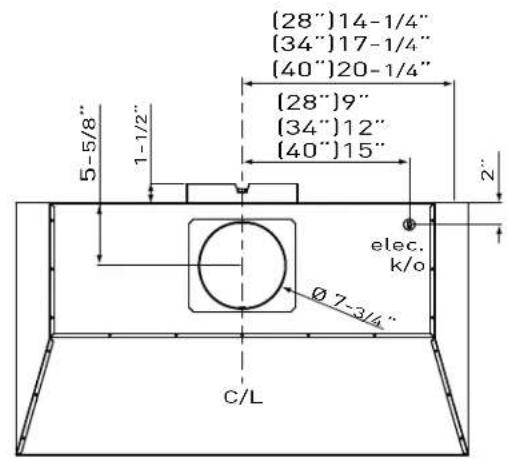
Top View
![[28"]9" [34"]12" [40"]15" elec. k/o φ7-3/4" 10-3/8" 3-1/4" C/L 9-7/8" 5-1/2"](/content/2026/07/1520250/images/4e6be90c9f54a0d0195b64a07d3b987f7fb3f13172b050d0acfe727195ea4c24.jpg)
Back View
ELECTRICAL
WARNING
All Electrical work must be performed by qualified electrician or person with similar technical know how and background.
For personal safety, remove house fuse or open circuit breaker before beginning installation. Do not use extension cord or adapter plug with this appliance.
Follow national electrical codes or prevailing local codes and ordinances.
Electrical Supply:
This appliance requires a 120V 60Hz electrical supply, and connected to an individual, properly grounded branch circuit, protected by a 15 or 20 ampere circuit breaker or time delay fuse. Wiring must be 2 wire w/ground. Please also refer Electrical Diagram labeled on product.
Cable Lock:
A cable locking connector (not supplied) might also be required by local codes. Check with local requirements and codes, purchase and install appropriate connector if necessary.
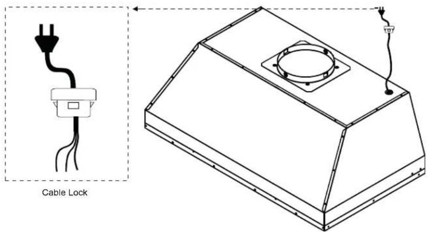

CAUTION: At least two installers are required due to the weight and size of the liner.
If possible, power up and test all functions prior to installation.
- Remove all packing materials and protective film prior to installation. Use caution during installation to prevent scratches or damage to the stainless steel.
- Cut out an opening in the bottom of the cabinet by following the dimensions in FIG. 1. If ducting the liner horizontally, also cut out an opening in the back of the cabinet (if applicable). FIG. 2.
- Prepare liner for installation into cabinet by following the steps on page 11 for vertical ducting or pages 12 -14 for horizontal ducting. Continue to Step 4 after preparation is completed.
- Lift liner into bottom opening of cabinet and secure to interior of cabinet using (8) #8 x 1/2" stainless steel screws; (4) screws in the front and (4) screws in the sides. FIG. 3.
WARNING: Make sure the surface you are securing the liner to is capable of holding the weight of AK94. Failure to do so may cause personal injury or damage to cooking surface or counter. - Finalize installation of electrical and duct work. Seal duct work with certifi ed aluminum duct tape. Power on liner, check for leaks around duct tape and verify proper operation.
NOTE: If access to top of liner is not available after installation, electrical and duct work connection may need to be made prior to installing the liner. - Re-install the previously removed bottom panel, side spacer panels (if applicable), grease tray, and baffl e filters.
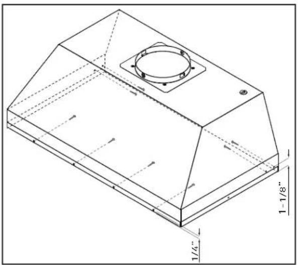
FIG. 3

FIG. 1
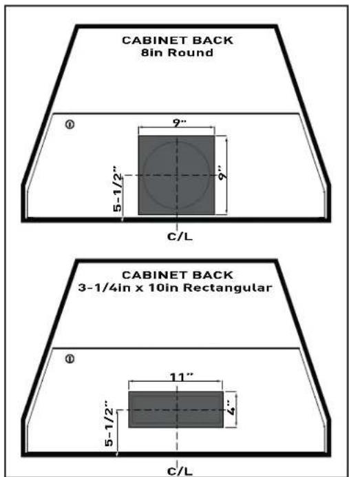
FIG. 2
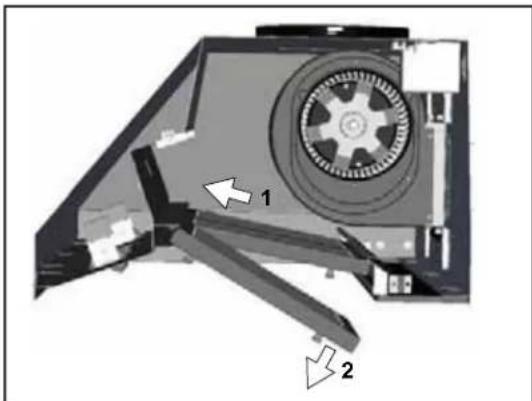
- Remove baffle filters by: 1) Pulling filter toward front of liner. 2) Pivoting rear of filter down.
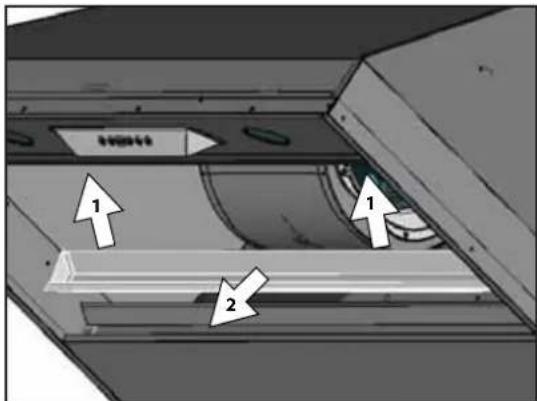
- Remove grease tray by: 1) Pulling up on tray to release from bottom panel. 2) Lifting tray out of liner body.

- (If applicable) Remove left and right side-spacer panels by removing (2) screws from behind each panel.
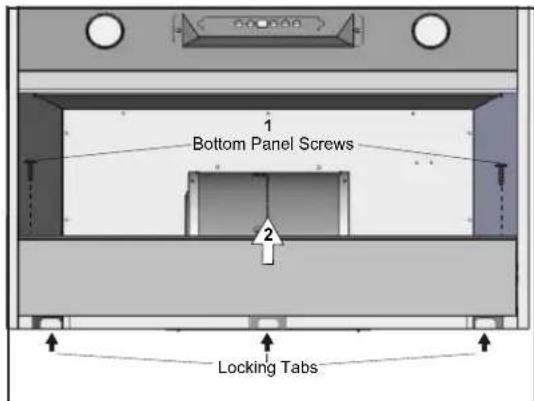
- Remove bottom panel by: 1) Removing (2) screws from left and right sides of bottom panel. 2) Pulling bottom panel toward front of liner to release from locking tabs.

- Secure 8" round adaptor to top of liner by (4) M4 x 6mm screws.
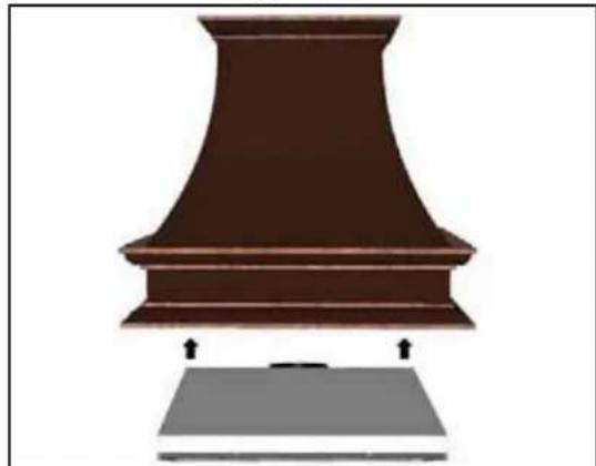
- Vertical ducting preparation is complete. Refer to page 10, step 4 to complete installation.
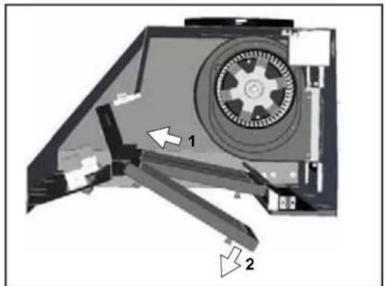
- Remove baffle filters by: 1) Pulling filter toward front of liner. 2) Pivoting rear of filter down.
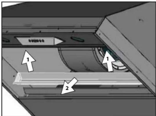
- Remove grease tray by: 1) Pulling up on tray to release from bottom panel. 2) Lifting tray out of liner body.
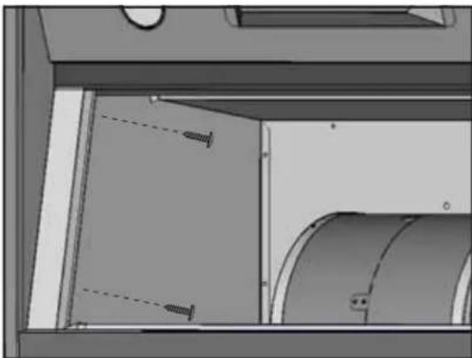
- (If applicable) Remove left and right side-spacer panels by removing (2) screws from behind each panel.

- Remove bottom panel by: 1) Removing (2) screws from left and right sides of bottom panel. 2) Pulling bottom panel toward front of liner to release from locking tabs.

- Disconnect blower molex plug.
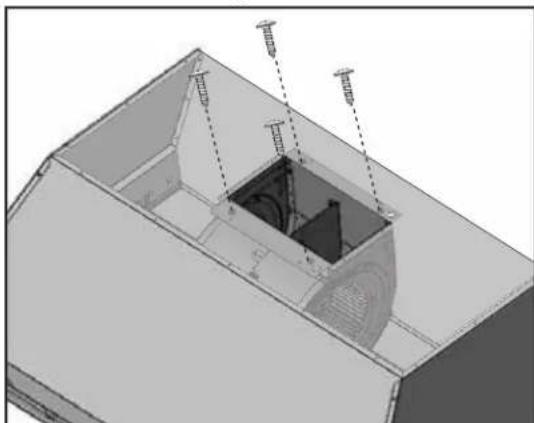
- Remove blower from liner by removing the (4) 3/16" x 3/8" screws from the top of the liner. Set screws aside for later usage.
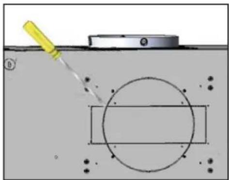
- Using a fl at head screwdriver, remove 8" round or 3 1/4"x10" rect. knock-out plates at the back of the liner.
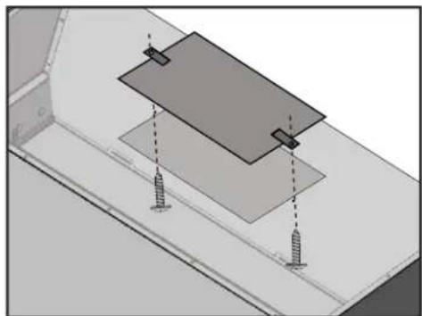
- Place top rectangular cover plate over opening on top of the liner. NOTE: Make sure the cover plate tabs are on top of the cover plate as shown. From inside the liner, secure plate to top of liner with (2) 3/16 x 3/8 screws.
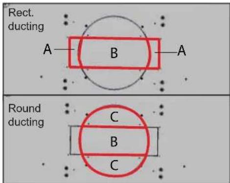
- Remove knock-outs A and B for rectangular ducting. Remove knock outs B and C for round ducting.
At this point, install the liner into the cabinet by following the steps on Page 10, Step 4. After liner installation, continue to page 14.
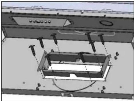
- (Rectangular Ducting) From inside the liner, push 3-1/4" x 10" rectangular adaptor through the back knock-out and secure to interior back wall of liner with (8) M4 x 6mm screws.
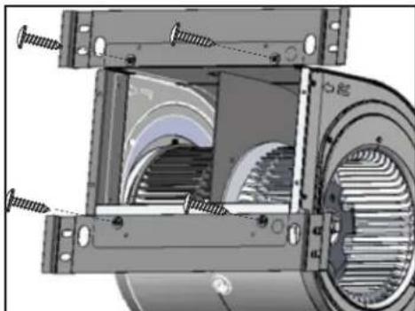
- Secure (2) horizontal ducting blower brackets to blower as shown above by using the (4) 3/16" x 3/8" screws previously removed from Page 12, Step 6; (2) screws for each bracket.

- Secure blower to captive nuts on interior back wall of liner with (8) 3/16" x 3/8" screws, (4) screws for each bracket. Seal any gaps around the knock-out plate by using certifi ed aluminum duct tape. Plug in blower molex plug.
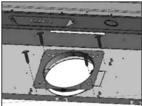
- (Round Ducting) From inside the liner, push 8" round adaptor through the back knock-out and secure to interior back wall of liner with (4) M4 x 6mm screws.

- Position blower inside liner body as shown by: 1) Rest the bottom horizontal ducting bracket on the two support clips located on the interior back wall of the liner. 2) Pivot top horizontal ducting bracket to meet captive nuts on interior back wall.
Horizontal ducting preparation is now complete. Refer to Page 10, Step 5 to complete installation.
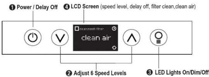
① Power / Delay Off Button ⏻
Power Button Function
- ⏻ Button will turn power on and off for entire liner (fan and lights).
- The liner controls will remember the last speed and light level it was turned off at.
(Example: Press Button to turn off liner when on fan Speed 4 and high lights. Press Button again and the liner will turn back on at Speed 4 and high lights level.)
Delay Off Button Function
- Press and hold Ⓤ Button for two-three seconds and the fan will turn on Speed 1. The ⏻ Graphic will illuminate. After five minutes the fan and lights will automatically turn off.
- Pressing Ⓐ Button while Delay Off Function is enabled will turn the liner off and cancel the Delay Off Function.
② Speed Selection Buttons √ ∧
Fan Speed Decrease Button √
- Press this button to decrease fan speed. 6 (burst), 5, 4, 3, 2, 1.
- If fan is on Speed 1 and this button is pressed, fan will power off.
Fan Speed Increase Button ⏰
- Press this button to increase fan speed. Fan On, 1, 2, 3, 4, 5, 6 (burst).
- If liner is off and this button is pressed, fan will turn on Speed 1.
Burst Mode
- This speed level is intended to be used as a quick burst of air extraction when excess cooking fumes and smoke are generated. After 3 minutes the fan will automatically change to Speed 5.
3 Lights Button
- The Zephyr Bloom®LED Lights are two levels, High and Low.
- From off, press one time for High. LCD will show the words "lights hi" for 2 seconds then fade away.
- Press again for Low. LCD will display the words "lights lo" for 2 seconds then fade away.
- Press again to power lights off.
4 LCD Screen
- Displays status information, see Page 16 for more information.
Mesh Filter Clean Indicator (always enabled)
- After 30 hours of fan usage the ■ Graphic and words "clean mesh filter" will illuminate indicating it is time to clean the mesh filters. Graphic and words will remain illuminated until reset.
- To reset: With liner off, hold the Ⓧ Button for three seconds, after three seconds the ▪ Graphic and words "clean mesh filter" will turn off and the 30 hour timer will reset.
Clean Air Indicator
- Clean Air is a feature that turns the fan on every 4 hours for 10 minutes to remove stagnant air in the kitchen.
- To enable Clean Air Function:
- With liner off, hold the Button and Button simultaneously for three seconds. The Graphic and words "clean air" will illuminate and the fan will turn on speed 1 for 10 minutes. After 10 minutes the fan will turn off and the 4 hour timer will begin.
- Graphic will remain on when Clean Air Function is enabled, even if fan is not on.
- To disable Clean Air Function:
- With liner off, hold the Button and Button simultaneously for three seconds until Graphic turns off.
- If the user changes the fan speed while the Clean Air Function is in use, the words "clean air" will turn off but the 📍 Graphic will remain illuminated. If the user presses the Ⓞ Button at any time the 4 hour clean air timer will reset.
FCC Caution: To assure continued compliance, any changes or modifications not expressly approved by the party responsible for compliance could void the user's authority to operate this equipment. (Example - use only shielded interface cables when connecting to computer or peripheral device. This device complies with Part 15 of the FCC Rules. Operation is subject to the following two conditions. (1) This device may not cause harmful interference, and (2) This device must accept any interference received, including interference that may cause undesired operation. This remote control may operate in humid environments, but not when placed on a wet surface.
SYNCHRONIZATION: To create a unique link between your range hood and remote control please follow the below steps:
- With range hood off, press and hold the "lights" button on the range hood until the LCD screen blinks on and off.
- Press the "lights" button on the remote, the lights on the hood will turn on. The synchronization is complete.
RF REMOTE FUNCTIONS:

① Blower On / Speed Selection
Press ↗ to power on blower and cycle through all six blower speeds.
② Blower On / Power Off
By pressing ⏻, the blowers will power on at the last speed setting. Press ⏻ again and the entire hood will power off, including lights.
③ Delay Off
By pressing ⏻, the blower and lights will enter Delay Off mode. The ⏻ graphic will illuminate indicating the function is on. The blower will change to speed 1 and shut down after 5 minutes.
④ Lights On / Dim / Off
Switch lights On by pressing once, again to dim and again to switch Off.
RF REMOTE FEATURES:
The RF remote control is equipped with a magnet on the back for easy storage. The remote may be placed on any magnetic surface such as a refrigerator or the Zephyr remote holder, FIG. 4. The remote holder can be inserted into a standard electrical outlet for easy storage. Note: The remote holder does not charge the RF remote.
Maximum remote control communication distance is 15 feet from the liner.
RF REMOTE MAINTENANCE:
Clean the remote control using non abrasive detergents
Follow instructions below for replacing battery.
Using a small fl at head screwdriver, raise the cover of the battery door (A) in order to access the battery compartment. FIG. 5.
Remove the battery and replace with battery type A23 12V.
Negative end of battery should face the spring inside the remote.
Re-install battery door and recycle old battery.
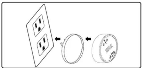
FIG. 4
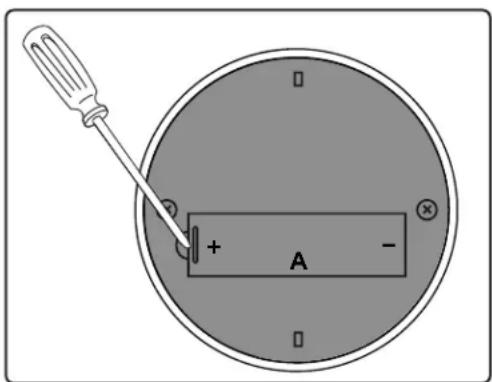
FIG. 5
SURFACE MAINTENANCE:
Clean periodically with hot soapy water and clean cotton cloth. Do not use corrosive or abrasive detergent, or steel wool/ scoring pads which will scratch and damage surface. Do not use products containing chlorine bleach or orange cleaners.
For heavier soil use liquid degreaser.
After cleaning, you may use non-abrasive stainless steel polish/ cleaners, to polish and buff out the stainless luster and grain. Always scrub lightly using a micro fiber or clean cotton cloth and with the grain.
Cleaning the Baffl e Filters
The filters are intended to trap residue and grease from cooking. Although the filters should never need replacing, they are required to be cleaned every 30 days or when the Clean Filter Indicator is illuminated on the liner controls.
Filters may be placed in dishwasher at low heat or soaked in hot soapy water Dry filters and re-install before using hood.
Installing the Baffle Filters, FIG. 6:
- Place filter into top groove of the liner as shown and pull towards front of liner using handles.
- Pivot back of filter upwards so it is angled in the liner.
- Push fi Iter into channel on back of liner to lock into place.
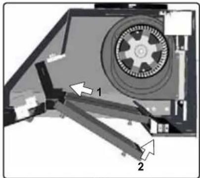
FIG. 6
| 50210013 | (large) | 2 |
| 1 | ||
| 3 |
Replacing the Baffl e Filters:
Hood Model: Part No. Qty. to Order
| AK9428AS | / | AK9434AS | |
| AK9434AS | 50210017 | (small) | |
| AK9440AS | 50210013 | (large) |
Cleaning the Grease Tray
The grease tray is intended to catch residue and grease that may drip from the baffl e fi Iters. The grease tray should be cleaned when baffl e fi Iters are cleaned. Clean the grease tray by soaking in hot soapy water and gently scrubing any residue off with a soft terry cloth. Dry grease tray and re-install before using liner.
Removing the Grease Tray
Grease tray has a hooked lip that attaches to bottom panel top edge.
Remove grease tray by:
- Pull up on tray to release from bottom panel. FIG. 7-1
- Pull tray out of insert body. FIG. 7-2

FIG. 7
TROUBLESHOOTING PROCEDURES FOR MONSOON DCBL
| Issue Cause What to do | ||
| After installation, the unit doesn't work. | 1. The power source is not turned ON. 1. Make sure | the circuit breaker and the unit's power is ON. |
| 2. The power line and the cable locking connector is not connecting properly. | 2. Check the power connection with the unit is connected properly. | |
| 3. The switch board and control board wires are disconnected. | 3. Make sure the wires between the switch board and control board are connected properly. | |
| 4. The wires on control board are loose. 4. Make sure | the wires on the control board are connected properly. | |
| 5. The switch board or control board is defective. 5. | Change the switch board or control board. | |
| Light works, but blower is not turning. | 1. The blower wire is not connected. 1. Make sure the blower wire is plugged into the molex connector. | |
| 2. The thermally protected system defects if the blower is too hot to operate and shuts the blower down. | 2. The blower will function properly after the thermally protected system cool down. | |
| 3. Damaged capacitor. 3. Change the capacitor. | ||
| 4. Blower molex plug pin is not making contact. 4. | Disconnect the blower molex plug, check pins inside plug to see if pin is pushed inside the plug too far. Reseat pin if needed. | |
| 5. The blower is defective, possibly seized. 5. Change the blower. | ||
| The unit is vibrating. | 1. The blower is not secure in place. 1. Tighten the blower in place. | |
| 2. The liner is not secured in place. 2. Check the installation of the liner. | ||
| 3. Damaged blower wheel. 3. Change the blower. | ||
| The unit is whistling. | 1. A filter is not in the correct position. | 1. Adjust the filters until the whistling stops. |
| 2. The duct pipe connections are not sealed or connected properly. | 2. Check the duct pipe connections to be sure all connections are sealed properly. | |
| The blower is working, but the lights are not. | 1. Defective LED bulb. | 1. Change the LED bulb. |
| 2. The light bulb plug is disconnected. | 2. Connect the light bulb plug. | |
| The hood is not venting out properly. | 1. The liner might be hanging too high from the cook top. | 1. Adjust the distance between the cook top and the bottom of the liner within 26" and 36" range. |
| 2. Wind from an opened window or opened doors in the surrounding area are affecting the ventilation of the liner. | 2. Close all the windows and doors to eliminate outside wind flow. | |
| 3. Blockage in the duct opening or duct work. | 3. Remove all the blocking from the duct work or duct opening. | |
| 4. The direction of duct opening is against the wind. | 4. Adjust the duct opening direction. | |
| 5. Using the wrong size of ducting. | 5. Change the ducting to correct size. | |
| Filter is vibrating. | 1. Filter is loose. | 1. Adjust or change the filter. |
| 2. Spring clip is broken on the filter. | 2. Change the spring clip. | |
| RF Remote control does not work | 1. Battery is dead. | 1. Replace battery with type A23 12v. |
| 2. Poor communication with the liner. | 2. Remote control must be within 15 ft of liner. | |
| 3. RF remote lost communication with the liner. | 3. Reset liner and remote by switching power off at the circuit breaker for 5 minutes. Perform remote synchronization process on page 17. | |

Model: AK9428AS / AK9434AS
Voltage: 120V 60Hz
Power consumption
Total: Max. 219W @ 3.5A
Lamp: Max. 6Wx2
Fan: Max. 207W
Electronically Protected

Model: AK9440AS
Voltage: 120V 60Hz
Power consumption
Total: Max. 225W @ 3.6A
Lamp: Max. 6Wx3
Fan: Max. 207W
Electronically Protected
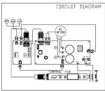
DESCRIPTION
PART #
Replacement Parts
AK9428AS / AK9434AS / AK9440AS Baffle Filter, Large (each) 50210013
AK9434AS Baffle Filter, Small (each)
50210017
RF Remote Control
14000005
To order parts, visit us online at http://store.zephyronline.com or call us at 1.888.880.8368
TO OBTAIN SERVICE UNDER WARRANTY OR FOR ANY SERVICE RELATED QUESTIONS, please call:
1-888-880-8368
Zephyr Corporation (referred to herein as “we” or “us”) warrants to the original consumer purchaser (referred to herein as “you” or “your”) of Zephyr products (the “Products”) that such Products will be free from defects in materials or workmanship as follows:
Three Year Limited Warranty for Parts and LED lamps: For three years from the date of your original purchase of the Products, we will provide, free of charge, Products or parts to replace those that failed due to manufacturing defects. We may choose, in our sole discretion, to repair or replace parts before we elect to replace the Products.
One Year Limited Warranty for Labor: For one year from the date of your original purchase of the Products, we will provide, free of charge, the labor cost associated with repairing the Products or parts to replace those that failed due to manufacturing defects. After the first year from the date of your original purchase, you are responsible for all labor costs associated with this warranty.
Warranty Exclusions: This warranty covers only repair or replacement, at our option, of defective Products or parts and does not cover any other costs related to the Products including but not limited to: (a) normal maintenance and service required for the Products and consumable parts such as metal and carbon filters and fuses; (b) any Products or parts which have been subject to freight damage, misuse, negligence, accident, faulty installation or installation contrary to recommended installation instructions, improper maintenance or repair (other than by us); (c) commercial use of the Products or use otherwise inconsistent with its intended purpose; (d) natural wear of the finish of the Products or wear caused by improper maintenance, use of corrosive and abrasive cleaning products, pads, and oven cleaner products; (e) chips, dents or cracks caused by abuse or misuse of the Products; (f) service trips to your home to teach you how to use the Products; or (g) damage to the Products caused by accident, fire, floods or act of God. If you are outside our service area, additional charges may apply for shipping costs for warranty repair at our designated service locations and for the travel cost to have a service technician come to your home to repair, remove or reinstall the Products. After the first year from the date of your original purchase, you are also responsible for all labor costs associated with this warranty.
Limitations of Warranty. OUR OBLIGATION TO REPAIR OR REPLACE, AT OUR OPTION, SHALL BE YOUR SOLE AND EXCLUSIVE REMEDY UNDER THIS WARRANTY. WE SHALL NOT BE LIABLE FOR INCIDENTAL, CONSEQUENTIAL OR SPECIAL DAMAGES ARISING OUT OF OR IN CONNECTION WITH THE USE OR PERFORMANCE OF THE PRODUCTS. THE EXPRESS WARRANTIES IN THE PRECEDING SECTION ARE EXCLUSIVE AND IN LIEU OF ALL OTHER EXPRESS WARRANTIES. WE HEREBY DISCLAIM AND EXCLUDE ALL OTHER EXPRESS WARRANTIES FOR THE PRODUCTS, AND DISCLAIM AND EXCLUDE ALL WARRANTIES IMPLIED BY LAW, INCLUDING THOSE OF MERCHANTABILITY AND FITNESS FOR A PARTICULAR PURPOSE. Some states or provinces do not allow limitations on the duration of an implied warranty or the exclusion or limitation of incidental or consequential damages, so the above limitations or exclusions may not apply to you. To the extent that applicable law prohibits the exclusion of implied warranties, the duration of any applicable implied warranty is limited to the same two-year period described above. Any oral or written description of the Products is for the sole purpose of identifying the Products and shall not be construed as an express warranty. Prior to using, implementing or permitting use of the Products, you shall determine the suitability of the Products for the intended use, and you shall assume all risk and liability whatsoever in connection with such determination. We reserve the right to use functionally equivalent refurbished or reconditioned parts or Products as warranty replacements or as part of warranty service. This warranty is not transferable from the original purchaser and applies in the United States and Canada.
To Obtain Service Under Limited Warranty: To qualify for warranty service, you must: (a) notify us at the address or telephone number stated below within 60 days of the discovery of the defect; (b) give the model number and part identification number and serial number; and (c) describe the nature of any defect in the Product or part. At the time of the request for warranty service, you must present evidence of your proof of purchase and proof of the original purchase date. If we determine that the warranty exclusions listed above apply or if you fail to provide the necessary documentation to obtain service, you will be responsible for all shipping, travel, labor and other costs related to the services.
Please check our website for any revisions, www.zephyronline.com.
Zephyr Corporation Service Department, 2277 Harbor Bay Parkway, Alameda, CA 94502 1-888-880-8368
Monsoon DCBL
AK9428AS
AK9434AS
AK9440AS


To reduce risk of fire and to properly exhaust air outside - Do not vent exhaust air into spaces within walls, ceilings, attics, crawl spaces or garages.
OPERATION
*National Fire Protection Association Batterymarch Park, Quincy, Massachusetts 02269
** CSA International 8501 East Pleasant Valley Road, Cleveland, Ohio 44131-5575
(10) 3/16" x 3/8"

Vue arrière
ÉLECTRICITÉ
AVERTISSEMENT
FIG. 3

FIG. 1

FIG. 2
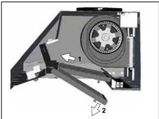
FIG. 4
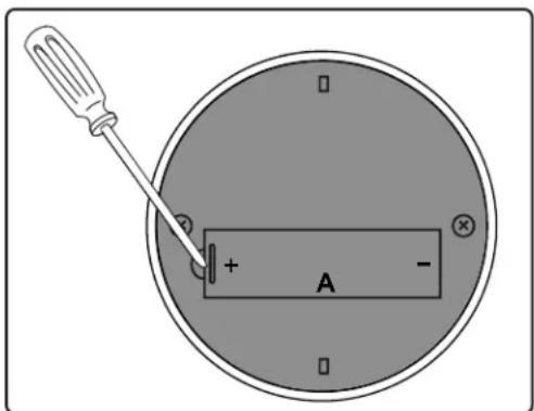
FIG. 5
ENTRETIEN DES SURFACES:
FIG. 7
PROCÉDURES DE DÉPANNAGE POUR LA HOTTE MONSOON DCBL
Total: Max. 219W @ 3.5A
Lampe: Max. 6Wx2
Total: Max. 225W @ 3.6A
Lampe: Max. 6Wx3
Zephyr Corporation Service Department, 2277 Harbor Bay Parkway, Alameda, CA 94502 1-888-880-8368


- INSTALLATION
- FEATURES & CONTROLS
- MAINTENANCE
- WARNING
- CAUTION
- OPERATION
- ELECTRICAL REQUIREMENTS
- IMPORTANT
- FEDERAL COMMUNICATION COMMISSION INTERFACE STATEMENT
- PARTS SUPPLIED
- PARTS NOT SUPPLIED
- DUCTING
- VERTICAL DUCTING
- HORIZONTAL DUCTING
- DAMAGE-SHIPMENT / INSTALLATION
- WARNING FIRE HAZARD
- SOME DUCTING OPTIONS
- ELECTRICAL
- ELECTRICAL SUPPLY
- CABLE LOCK
- ① POWER / DELAY OFF BUTTON ⏻
- POWER BUTTON FUNCTION
- DELAY OFF BUTTON FUNCTION
- ② SPEED SELECTION BUTTONS √ ∧
- FAN SPEED DECREASE BUTTON √
- FAN SPEED INCREASE BUTTON ⏰
- BURST MODE
- 3 LIGHTS BUTTON
- 4 LCD SCREEN
- MESH FILTER CLEAN INDICATOR (ALWAYS ENABLED)
- CLEAN AIR INDICATOR
- RF REMOTE FEATURES
- RF REMOTE MAINTENANCE
- FOLLOW INSTRUCTIONS BELOW FOR REPLACING BATTERY
- SURFACE MAINTENANCE
- CLEANING THE BAFFL E FILTERS
- INSTALLING THE BAFFLE FILTERS, FIG. 6
- REPLACING THE BAFFL E FILTERS
- CLEANING THE GREASE TRAY
- REMOVING THE GREASE TRAY
- DESCRIPTION
- PART
- TO OBTAIN SERVICE UNDER WARRANTY OR FOR ANY SERVICE RELATED QUESTIONS, PLEASE CALL
- 1-888-880-8368
- MONSOON DCBL
- ÉLECTRICITÉ
- AVERTISSEMENT
- ENTRETIEN DES SURFACES
Brand : Zephyr
Model : AK9428AS
Category : Range hood