
PR-SC5507 - Audio/Video Preamplifier ONKYO - Free user manual and instructions
Find the device manual for free PR-SC5507 ONKYO in PDF.
| Product type | Audio/Video Preamplifier |
| Brand | ONKYO |
| Model | PR-SC5507 |
| Dimensions (W x H x D) | 435 x 175 x 435 mm |
| Weight | 18 kg |
| Power supply | 220-240 V AC, 50/60 Hz |
| Power consumption | 80 W (standby: 0.3 W) |
| HDMI inputs | 6 (HDMI 1.3a) |
| HDMI outputs | 1 |
| Compatible audio formats | Dolby TrueHD, DTS-HD Master Audio, Dolby Digital Plus, DTS-HD High Resolution Audio, multi-channel LPCM |
| THX certification | THX Ultra2 Plus |
| Acoustic calibration | Audyssey MultEQ XT |
| Network connectivity | Ethernet, USB port for firmware update |
| Preamplifier outputs | 11.2 channels (XLR and RCA) |
| Analog audio inputs | 7 RCA pairs, 1 stereo XLR pair |
| Digital inputs | 4 optical, 3 coaxial |
| Remote control | RI (Remote Interactive) with control via RS232 |
| Maintenance and cleaning | Dust with a soft, dry cloth. Do not use chemical products. |
| Safety | Unplug before cleaning. Use a polarized plug. Do not expose to moisture. |
| Spare parts and repairability | Contact an authorized ONKYO dealer for parts. Professional repair recommended. |
Frequently Asked Questions - PR-SC5507 ONKYO
User questions about PR-SC5507 ONKYO
0 question about this device. Answer the ones you know or ask your own.
Ask a new question about this device
Download the instructions for your Audio/Video Preamplifier in PDF format for free! Find your manual PR-SC5507 - ONKYO and take your electronic device back in hand. On this page are published all the documents necessary for the use of your device. PR-SC5507 by ONKYO.
USER MANUAL PR-SC5507 ONKYO
Thank you for purchasing an Onkyo AV Controller. Please read this manual thoroughly before making connections and plugging in the unit. Following the instructions in this manual will enable you to obtain optimum performance and listening enjoyment from your new AV Controller. Please retain this manual for future reference.
Contents
Introduction 2
Connection 18
Turning On & First Time Setup.....43
Basic Operations. 62
Using the Listening Modes 75
Advanced Setup 86
NET/USB 115
Multi Zone 125
Controlling Other Components....133
Others. 148
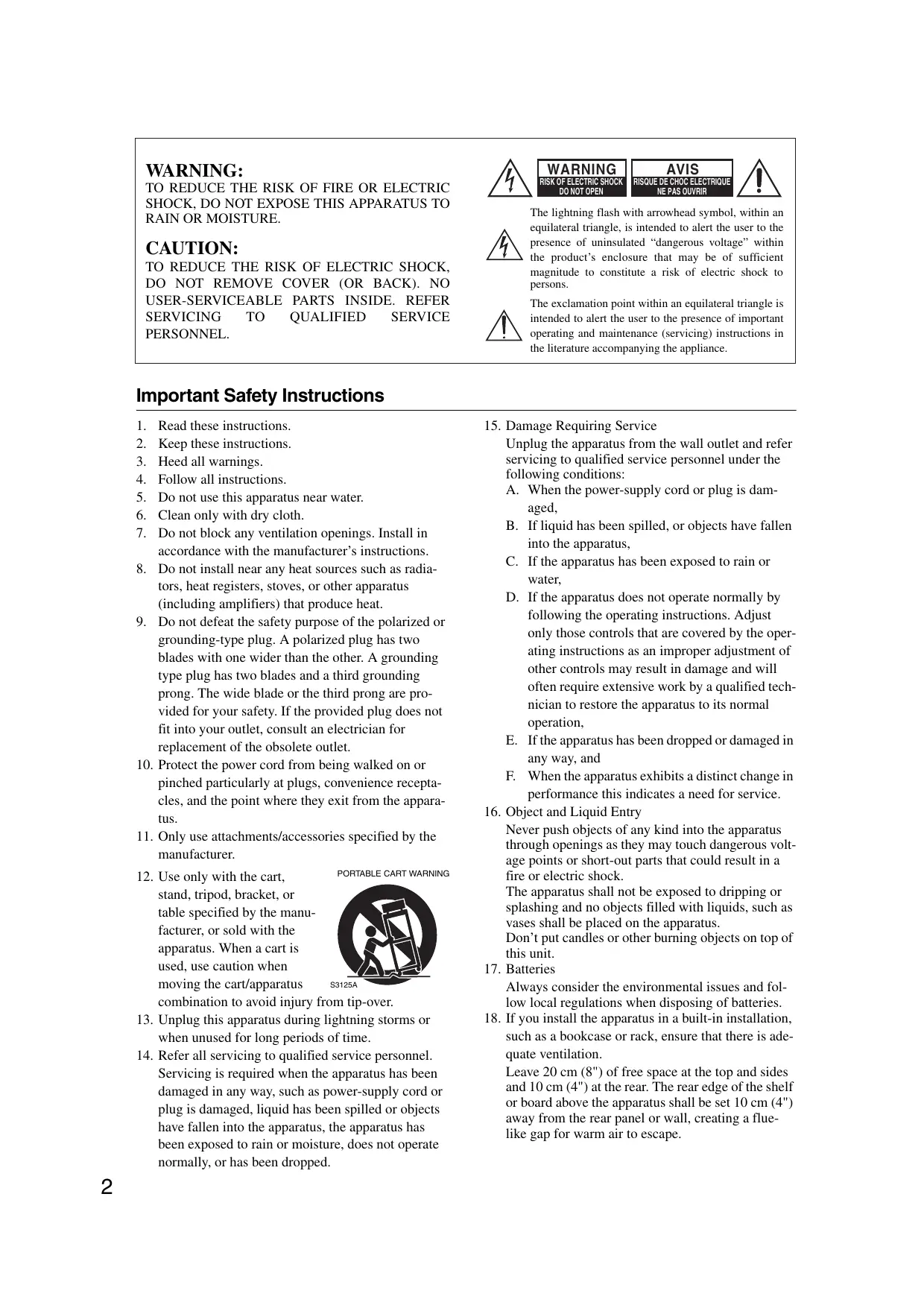
WARNING:
TO REDUCE THE RISK OF FIRE OR ELECTRIC SHOCK,DO NOT EXPOSE THIS APPARATUS TO RAIN OR MOISTURE.
CAUTION:
TO REDUCE THE RISK OF ELECTRIC SHOCK, DO NOT REMOVE COVER (OR BACK). NO USER-SERVICEABLE PARTS INSIDE. REFER SERVICING TO QUALIFIED SERVICE PERSONNEL.

WARNING
RISK OF ELECTRIC SHOCK
DO NOT OPEN
AVIS
RISQUE DE CHOC ELECTRIQUE
NE PAS OUVRIR


The lightning flash with arrowhead symbol, within an equilateral triangle, is intended to alert the user to the presence of uninsulated "dangerous voltage" within the product's enclosure that may be of sufficient magnitude to constitute a risk of electric shock to persons.

The exclamation point within an equilateral triangle is intended to alert the user to the presence of important operating and maintenance (servicing) instructions in the literature accompanying the appliance.
Important Safety Instructions
- Read these instructions.
- Keep these instructions.
- Heed all warnings.
- Follow all instructions.
- Do not use this apparatus near water.
- Clean only with dry cloth.
- Do not block any ventilation openings. Install in accordance with the manufacturer's instructions.
- Do not install near any heat sources such as radiators, heat registers, stoves, or other apparatus (including amplifiers) that produce heat.
- Do not defeat the safety purpose of the polarized or grounding-type plug. A polarized plug has two blades with one wider than the other. A grounding type plug has two blades and a third grounding prong. The wide blade or the third prong are provided for your safety. If the provided plug does not fit into your outlet, consult an electrician for replacement of the obsolete outlet.
- Protect the power cord from being walked on or pinched particularly at plugs, convenience receptacles, and the point where they exit from the apparatus.
- Only use attachments/accessories specified by the manufacturer.
- Use only with the cart, stand, tripod, bracket, or table specified by the manufacturer, or sold with the apparatus. When a cart is used, use caution when moving the cart/apparatus combination to avoid injury
- Unplug this apparatus during lightning storms or when unused for long periods of time.
-
Refer all servicing to qualified service personnel. Servicing is required when the apparatus has been damaged in any way, such as power-supply cord or plug is damaged, liquid has been spilled or objects have fallen into the apparatus, the apparatus has been exposed to rain or moisture, does not operate normally, or has been dropped.
-
Damage Requiring Service
Unplug the apparatus from the wall outlet and refer servicing to qualified service personnel under the following conditions:
A. When the power-supply cord or plug is damaged,
B. If liquid has been spilled, or objects have fallen into the apparatus,
C. If the apparatus has been exposed to rain or water,
D. If the apparatus does not operate normally by following the operating instructions. Adjust only those controls that are covered by the operating instructions as an improper adjustment of other controls may result in damage and will often require extensive work by a qualified technician to restore the apparatus to its normal operation,
E. If the apparatus has been dropped or damaged in any way, and
F. When the apparatus exhibits a distinct change in performance this indicates a need for service.
- Object and Liquid Entry
Never push objects of any kind into the apparatus through openings as they may touch dangerous voltage points or short-out parts that could result in a fire or electric shock.
The apparatus shall not be exposed to dripping or splashing and no objects filled with liquids, such as vases shall be placed on the apparatus.
Don't put candles or other burning objects on top of this unit.
- Batteries
Always consider the environmental issues and follow local regulations when disposing of batteries.
- If you install the apparatus in a built-in installation, such as a bookcase or rack, ensure that there is adequate ventilation.
Leave 20cm (8") of free space at the top and sides and 10cm (4") at the rear. The rear edge of the shelf or board above the apparatus shall be set 10cm (4") away from the rear panel or wall, creating a flue-like gap for warm air to escape.
-
Recording Copyright—Unless it's for personal use only, recording copyrighted material is illegal without the permission of the copyright holder.
-
AC Fuse—The AC fuse inside the unit is not user-serviceable. If you cannot turn on the unit, contact your Onkyo dealer.
-
Care—Occasionally you should dust the unit all over with a soft cloth. For stubborn stains, use a soft cloth dampened with a weak solution of mild detergent and water. Dry the unit immediately afterwards with a clean cloth. Don't use abrasive cloths, thinners, alcohol, or other chemical solvents, because they may damage the finish or remove the panel lettering.
4. Power
WARNING
BEFORE PLugging IN THE UNIT FOR THE FIRST TIME, READ THE FOLLOWING SECTION CAREFULLY.
AC outlet voltages vary from country to country. Make sure that the voltage in your area meets the voltage requirements printed on the unit's rear panel (e.g., AC 230 V, 50 Hz or AC 120 V, 60 Hz).
The power cord plug is used to disconnect this unit from the AC power source. Make sure that the plug is readily operable (easily accessible) at all times.
Pressing the [ON/STANDBY] button to select Standby mode does not fully shutdown the unit. If you do not intend to use the unit for an extended period, remove the power cord from the AC outlet.
5. Preventing Hearing Loss
Caution
Excessive sound pressure from earphones and headphones can cause hearing loss.
6. Batteries and Heat Exposure Warning
Batteries (battery pack or batteries installed) shall not be exposed to excessive heat as sunshine, fire or the like.
- Never Touch this Unit with Wet Hands—Never handle this unit or its power cord while your hands are wet or damp. If water or any other liquid gets inside this unit, have it checked by your Onkyo dealer.
8. Handling Notes
- If you need to transport this unit, use the original packaging to pack it how it was when you originally bought it.
- Do not leave rubber or plastic items on this unit for a long time, because they may leave marks on the case.
- This unit's top and rear panels may get warm after prolonged use. This is normal.
- If you do not use this unit for a long time, it may not work properly the next time you turn it on, so be sure to use it occasionally.
For U.S. models
FCC Information for User
CAUTION:
The user changes or modifications not expressly approved by the party responsible for compliance could void the user's authority to operate the equipment.
NOTE:
This equipment has been tested and found to comply with the limits for a Class B digital device, pursuant to Part 15 of the FCC Rules. These limits are designed to provide reasonable protection against harmful interference in a residential installation.
This equipment generates, uses and can radiate radio frequency energy and, if not installed and used in accordance with the instructions, may cause harmful interference to radio communications. However, there is no guarantee that interference will not occur in a particular installation. If this equipment does cause harmful interference to radio or television reception, which can be determined by turning the equipment off and on, the user is encouraged to try to correct the interference by one or more of the following measures:
- Reorient or relocate the receiving antenna.
- Increase the separation between the equipment and receiver.
- Connect the equipment into an outlet on a circuit different from that to which the receiver is connected.
- Consult the dealer or an experienced radio/TV technician for help.
For Canadian Models
NOTE: THIS CLASS B DIGITAL APPARATUS COMPLIES WITH CANADIAN ICES-003.
For models having a power cord with a polarized plug: CAUTION: TO PREVENT ELECTRIC SHOCK, MATCH WIDE BLADE OF PLUG TO WIDE SLOT, FULLY INSERT.
Replacement and mounting of an AC plug on the power supply cord of this unit should be performed only by qualified service personnel.
IMPORTANT
The wires in the mains lead are coloured in accordance with the following code:
Blue: Neutral
Brown: Live
As the colours of the wires in the mains lead of this apparatus may not correspond with the coloured markings identifying the terminals in your plug, proceed as follows:
The wire which is coloured blue must be connected to the terminal which is marked with the letter N or coloured black.
The wire which is coloured brown must be connected to the terminal which is marked with the letter L or coloured red.
IMPORTANT
The plug is fitted with an appropriate fuse. If the fuse needs to be replaced, the replacement fuse must approved by ASTA or BSI to BS1362 and have the same ampere rating as that indicated on the plug. Check for the ASTA mark or the BSI mark on the body of the fuse. If the power cord's plug is not suitable for your socket outlets, cut it off and fit a suitable plug. Fit a suitable fuse in the plug.
For European Models
Declaration of Conformity
We, ONKYO EUROPE
ELECTRONICS GmbH
LIEGNITZERSTRASSE
82194 GROEBENZELL
GERMANY

declare in own responsibility, that the ONKYO product described in this instruction manual is in compliance with the corresponding technical standards such as EN60065, EN55013, EN55020 and EN61000-3-2, -3-3.
GROEBENZELL, GERMANY

ONKYO EUROPE ELECTRONICS GmbH
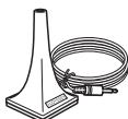
Supplied Accessories
Make sure you have the following accessories:
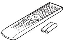
Remote controller & two batteries (AA/R6)
(Note for China: The battery for the remote controller is not supplied for this unit.)
Speaker setup microphone

Indoor FM antenna
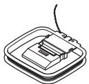
AM loop antenna
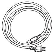
Power cord
(Plug type varies from country to country.)
Introduction
Important Safety Instructions 2
Precautions 3
Supplied Accessories 4
Features 6
Front & Rear Panels 8
Front Panel 8
Display 10
Rear Panel 11
Remote Controller. 14
Installing the Batteries. 14
Aiming the Remote Controller 14
Controlling the AV Controller 15
About Home Theater 17
Enjoying Home Theater 17
Connection
Connecting the AV controller 18
Connecting Your Speakers 18
Connecting a Power Amplifier with RCA Inputs. 19
Connecting a Power Amplifier with XLR Inputs 20
Bi-amping the Front Speakers 21
Connecting Antenna 22
About AV Connections 24
Connecting Components with HDMI 25
Connecting Both Audio & Video 28
Which Connections Should I Use? 28
Connecting a TV or Projector. 31
Connecting a DVD Player 32
Connecting a VCR or DVD Recorder for Playback.....34
Connecting a VCR or DVD Recorder for Recording...35
Connecting a Satellite, Cable, Terrestrial Set-top box, or Other Video Source 36
Connecting a Game Console 37
Connecting a Camcorder or Other Device 38
Connecting a CD Player or Turntable 39
Connecting a Cassette, CDR, MiniDisc, or DAT Recorder 40
Connecting a Balanced Audio Source 40
Connecting an RI Dock. 41
Connecting a Universal Port Option Series 41
Connecting Onkyo RI Components 42
Connecting the Power Cord 42
Turning On & First Time Setup
Turning On the AV controller 43
Turning On and Standby 43
First Time Setup 44
Monitor Setup. 44
Selecting the Language used for the onscreen setup menus 45
Using the Onscreen Setup Menus 46
Using the Display to change the settings. 46
Monitor Out Setup. 47
Video Input Setup 49
Digital Audio Input Setup 51
Analog Audio Input Setup 52
Speaker Settings. 53
TV Format Setup (European and Asian models) 54
FM/AM Frequency Step Setup. 54
Changing the Input Display 55
Audyssey MultEQXT Room Correction and Speaker Setup. 56
Basic Operations
Basic Operations 62
Selecting the Input Source 62
Adjusting the Bass & Treble 63
Displaying Source Information 63
Setting the Display Brightness 64
Muting the AV Controller 64
Using the Sleep Timer 64
Using Headphones 64
Using Easy Macros 65
Listening to the Radio 67
Using the Tuner 67
Preseting AM/FM Stations 68
Using RDS (European models) 69
Universal Port Option UP-A1 Dock for iPod 71
About the UP-A1 Dock 71
Compatible iPod models. 71
Function Overview 71
Controlling iPod 72
Recording 74
Using the Listening Modes
Using the Listening Modes 75
Selecting Listening Modes 75
Listening Modes Available for Each Source Format... 76
About the Listening Modes 83
Advanced Setup
Advanced Setup 86
Onscreen Setup Menus 86
Input/Output Assign 87
Speaker Setup 90
Audio Adjust 94
Source Setup 98
Assigning Listening Modes to Input Sources. 104
Miscellaneous (Volume/OSD) Setup 105
Hardware Setup. 106
Lock Setup. 111
Digital Input Signal Formats 111
Using the Audio Settings 112
NET/USB
NET/USB 115
About NET 115
Connecting the AV Controller 115
Listening to Internet Radio 116
Playing Music Files on a Server 117
Network Settings 121
About USB 122
Playing Music Files on a USB Device 123
Multi Zone
Multi Zone 125
Multiroom Capability 125
Connecting Zone 2 126
Connecting Zone 3 127
Setting the Multi Zone 128
Using Zone 2/3 129
Using the 12V Triggers. 131
Using the Remote Controller in Zone 2/3 and
Multiroom Control Kits. 132
Controlling Other Components
Controlling Other Components 133
Preprogrammed Remote Control Codes 133
Looking up for Remote Control Code 133
Entering Remote Control Codes. 135
Remote Control Codes for Onkyo Components
Connected via RI. 136
Resetting REMOTE MODE Buttons 136
Resetting the Remote Controller 136
Controlling a TV. 137
Controlling a DVD Player or DVD Recorder 138
Controlling a VCR or PVR 139
Controlling a Satellite Receiver or Cable Receiver... 140
Controlling a CD Player, CD Recorder or MD Recorder ... 141
Controlling an RI Dock. 142
Controlling a Cassette Recorder 143
Activities Setup 144
Learning Commands 146
Using Normal Macros 147
Others
Troubleshooting 148
Specifications 154
Video Resolution Chart. 155
- To reset the AV controller to its factory defaults, turn it on and, while holding down the [VCR/DVR] button, press the [ON/STANDBY] button (see page 148).
Processing
THX Ultra2 Plus1 Certified
HQV-Reon-VX Video Processing with 1080p Video Upscaling of All Video Sources via HDMI
- HDMI ver.1.3a with (Deep Color, x.v.Color, Lip Sync, DTS ^2 -HD Master Audio, Dolby TrueHD ^3 , DSD and Multi-CH PCM)
- Dolby Pro Logic IIz*3 - New Surround Format (front-high)
Audyssey Dynamic Surround ExpansionTM*8 for New Surround Channels (front-wide/front-high)
- DTS Surround Sensation Speaker/Headphone Technology2
- 4 DSP Modes for Gaming; Rock/Sports/Action/RPG
Non-Scaling Configuration
- Direct Mode and Pure Audio Mode
- Music Optimizer4 for Digital Music Files
A-Form Listening Mode Memory
- Latest Burr-Brown 192kHz / 32 -Bit DACs Improve Jitter Performance for Cleaner Sound
- Three TI (Aureus) 32-bit Processing DSP
- Neural Surround Decoding9
- DSD Direct
Connections
Balanced XLR stereo input
- Balanced XLR 9.2-channel preouts, with front biamping capability
- 8 HDMI5 Inputs and 2 Outputs
- Onkyo R1HD for System Control
7 Digital Inputs (4 Optical/3 Coaxial)
- Universal Port for UP-A1 (Dock for the iPod)/HD Radio™6 tuner module (North American models)/DAB+ tuner module (European models)
- SIRIUS7 Satellite Radio Connectivity (North American models)
- Internet Radio Connectivity (SIRIUS Internet Radio ^7 /vTuner/Last.fm/Pandora/Rhapsody)
- Services available may vary depending on the region.
Network Capability for Streaming Audio Files
- USB Port for a USB Mass Storage Device (Audio Only)
Miscellaneous
40 SIRIUS*7/AM/FM Presets (North American models)
40 AM/FM Presets (European and Asian models)
Dolby Volume*3
- Audyssey MultEQ® XT*8 to Correct Room Acoustic Problems
Audyssey Dynamic EQ^TM^ 8 for Loudness Correction
Audyssey Dynamic VolumeTM*8
Crossover Adjustment (40/50/60/70/80/90/100/120/150/200 Hz)
A/V Sync Control Function (up to 250~ms
- Bi-Directional Preprogrammed (with onscreen display setup) RI-Compatible Learning Remote with 4 Activities and Mode-Key LEDs
- ISF (Imaging Science Foundation) Video Calibration
\*1. IHX
THX and Ultra2 Plus are trademarks of THX Ltd. THX may be registered in some jurisdictions. All rights reserved. Surround EX is a trademark of Dolby Laboratories. Used with permission.
\*2. Master Audio

Manufactured under license under U.S. Patent #s: 5,451,942; 5,956,674; 5,974,380; 5,978,762; 6,226,616; 6,487,535;
7,212,872; 7,333,929; 7,392,195; 7,272,567 & other U.S. and worldwide patents issued & pending. DTS is a registered trademark & the DTS logos, Symbol, DTS-HD Master Audio and DTS Surround Sensation are trademarks of DTS, Inc. ©1996-2008 DTS, Inc. All Rights Reserved.
Manufactured under license from Dolby Laboratories. "Dolby", "Pro Logic", "Surround EX" and the double-D symbol are trademarks of Dolby Laboratories.
*4. Music Optimizer™ is a trademark of Onkyo Corporation.
*5. HOMI
HDMI, the HDMI logo and High Definition Multimedia Interface are trademarks or registered trademarks of HDMI Licensing, LLC.
^*6 Radio
HD Radio™ and the HD Radio Ready logo are proprietary trademarks of iBiquity Digital Corporation. To receive HD Radio broadcasts, you must install an Onkyo UP-HT1 HD Radio tuner module (sold separately).
\*7. SIRIUS

SIRIUS, XM and all related marks and logos are trademarks of Sirius XM Radio Inc. and its subsidiaries. All other marks and logos are the property of their respective owners. All rights reserved. SIRIUS and XM subscriptions sold separately. Taxes and a one-time activation fee may apply. XM tuners and home docks or SIRIUS tuners (each sold separately) are required to receive the SIRIUS or XM satellite radio service. All programming and fees subject to change. It is prohibited to copy, decompile, disassemble, reverse engineer, hack, manipulate or otherwise make available any technology or software incorporated in receivers compatible with the SIRIUS or XM Satellite Radio Systems. Service not available in Alaska and Hawaii.
*8.


Manufactured under license from Audyssey Laboratories. U.S. and foreign patents pending. Audyssey MultEQ® XT, Audyssey Dynamic Surround Expansion™, Audyssey Dynamic Volume™ and Audyssey Dynamic EQ™ are trademarks of Audyssey Laboratories.
*9.

Neural Surround is a trademark owned by Neural Audio Corporation, THX is a trademark of THX Ltd., which may be registered in some jurisdictions. All rights reserved.
THX Ultra2 Plus
Before any home theater component can be THX Ultra2 Plus certified, it must pass a rigorous series of quality and performance tests. Only then can a product feature the THX Ultra2 Plus logo, which is your guarantee that the Home Theater products you purchase will give you superb performance for many years to come. THX Ultra2 Plus requirements define hundreds of parameters, including power amplifier performance, and pre-amplifier performance and operation for both digital and analog domains. THX Ultra2 Plus receivers also feature proprietary THX technologies (e.g., THX Mode) which accurately translate movie soundtracks for home theater playback.
- “Xantech” is a registered trademark of Xantech Corporation.
- "Niles" is a registered trademark of Niles Audio Corporation.
- Apple and iPod are trademarks of Apple Inc., registered in the U.S. and other countries.
* "x.v.Color" is a trademark of Sony Corporation. - Rhapsody and the Rhapsody logo are registered trademarks of RealNetworks, Inc.
- "DLNA®, the DLNA Logo and DLNA CERTIFIED™ are trademarks, service marks, or certification marks of the Digital Living Network Alliance."
- Re-Equalization and the "Re-EQ" logo are trademarks of THX Ltd.
This product incorporates copyright protection technology that is protected by U.S. patents and other intellectual property rights. Use of this copyright protection technology must be authorized by Macrovision Corporation, and is intended for home and other limited consumer uses only unless otherwise authorized by Macrovision. Reverse engineering or disassembly is prohibited.
Front Panel
The actual front panel has various logos printed on it. They are not shown here for clarity.
The page numbers in parentheses show where you can find the main explanation for each item.
① ON/STANDBY button (43)
This button is used to set the AV controller to On or Standby.
② STANDBY indicator (43)
Lights when the AV controller is in Standby mode, and it flashes while a signal is being received from the remote controller.
③ ZONE 2 indicator (129)
Lights when Zone 2 is selected.
④ ZONE 3 indicator (129)
Lights when Zone 3 is selected.
⑤ Input selector buttons (62)
These buttons are used to select from the following input sources: DVD/BD, VCR/DVR, CBL/SAT, GAME, AUX 1, AUX 2, TV/TAPE, TUNER, CD, PHONO, PORT, NET/USB.
^6 Remote control sensor/transmitter (14)
The sensor receives control signals from the remote controller. The transmitter transmits setting data to the remote controller.
⑦ Display
See "Display" on page 10.
(8) MASTER VOLUME control (62) and indicator
This control is used to adjust the volume of the AV controller to - dB, -81.5 dB through +18.0 dB (relative display).
The volume level can also be displayed as an absolute value. See "Volume Setup" on page 105.
PURE AUDIO button (75)
Selects the Pure Audio listening mode. Pressing this button again selects the previous listening mode.
(North American models)
(European and Asian models)

The page numbers in parentheses show where you can find the main explanation for each item.
10 PHONES jack (64)
This 1/4-inch phone jack is for connecting a standard pair of stereo headphones for private listening.
① ZONE 2, ZONE 3, and OFF buttons (129)
The [ZONE 2] button is used to select Zone 2.
The [ZONE 3] button is used to select Zone 3.
The [OFF] button is used to turn off Zone 2 or Zone 3.
TONE button (63, 130)
Used to select the tone (bass and treble) for the main room, and the tone and balance for Zone 2 or Zone 3.
LEVEL button (130)
Used to select the volume level of Zone 2 or Zone 3.
14 MONITOR OUT button (44)
Used to set the "Monitor Out" setting.
LISTENING MODE buttons (75)
MOVIE/TV:
Selects the listening modes intended for use with movies and TV.
MUSIC:
Selects the listening modes intended for use with music.
GAME:
Selects the listening modes intended for use with video games.
THX:
Selects the THX listening modes.
DIMMER button (64)
(North American models)
This button is used to adjust the display brightness.
RT/PTY/TP button (69)
(European and Asian models)
This button is used for RDS (Radio Data System). The [RT/PTY/TP] button does not work in areas where RDS broadcasts are not available. See "Using RDS (European models)" on page 69.
⑦ MEMORY button (68)
This button is used when storing or deleting radio presets.
TUNING MODE button (67)
This button is used to select the Auto or Manual tuning mode.
19 Arrow, TUNING, PRESET and ENTER buttons
When the AM or FM input source is selected, the TUNING [] / [] buttons are used to tune the tuner, and the PRESET [] / [] buttons are used to select radio presets (see pages 68 and 70).
When the onscreen setup menus are used, they work as arrow buttons and are used to select and set items. The [ENTER] button is also used with the onscreen setup menus.
20 SETUP button
This button is used to access the onscreen setup menus that appear on the connected TV.
2 RETURN button
This button is used to return to the previously displayed onscreen setup menu.
2 SETUP MIC jack (57)
Audyssey MultEQXT Room Correction and Speaker Setup microphone connects here.
USB port (122)
A USB mass storage device, such as a USB flash drive or MP3 player, containing music files can be plugged in here and the music selected can be played through the AV controller.
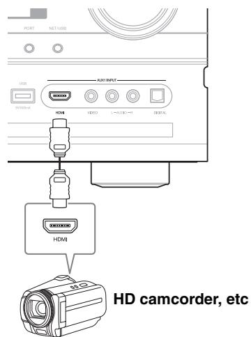
AUX1 INPUT (38)
This input can be used to connect a camcorder, game console, and so on. There are jacks for composite video, analog audio, and optical digital audio.
AUX1 INPUT HDMI (27)
Used to connect an HD camcorder etc.
Up [▶] and Down [<] buttons (63, 130)
Used to adjust the tone (bass and treble) for the main room and the volume, tone and balance for Zone 2 or Zone 3.
DISPLAY button (63)
This button is used to display various information about the currently selected input source.
⑦ POWER switch (43)
(European and Asian models)
This is the main power switch. When set to OFF, the AV controller is completely shutdown. It must be set to ON to set the AV controller to On or Standby.

Display
For detailed information, see the pages in parentheses.
① Speaker/channel indicators
Indicate the speaker channels used by the current listening mode.
The following abbreviations indicate which audio channels are outputted for the current listening mode.
LW: Front wide left
LH: Front high left
RH: Front high right
RW: Front wide right
FL: Front left
C: Center
FR: Front right
SL: Surround left
SW: Subwoofer (Low Frequency Effects)
SR: Surround right
SBL: Surround back left
SB: Surround back
SBR: Surround back right
② Listening mode and format indicators (75)
Show the selected listening mode and audio input signal format.
Audyssey (56, 92):
Flashes during Audyssey MultEQ® XT Room Correction and Speaker Setup. Lights when the "Equalizer Settings" is set to "Audyssey" or
Audyssey Dynamic Surround Expansion™ listening mode is selected.
Dynamic EQ (96):
Lights when "Dynamic EQ" is enabled.
Vol (96, 113):
Lights when "Dynamic Volume" is enabled.
Vol (95, 113):
Lights when "Dolby Volume" is enabled.
③ NETWORK indicator (116)
Lights when the Net input selector is selected.
④ Tuning indicators
RDS (European models) (69):
Lights when tuned to a radio station that supports
RDS (Radio Data System).
AUTO (67):
Lights when Auto Tuning mode is selected for AM or FM radio. Goes off when Manual Tuning mode is selected.
TUNED (67):
Lights when tuned to a radio station.
FM STEREO (67):
Lights when tuned to a stereo FM station.
⑤ SLEEP indicator (64)
Lights when the Sleep function has been set.
⑥ Bi AMP indicator (21)
Lights when the "Speakers Type(Front)" setting is set to "Bi-Amp".
⑦ Headphone indicator (64)
Lights when a pair of headphones are plugged into the PHONES jack.
⑧ Message area
Displays various information.
USB indicator (123)
Lights up when a USB mass storage device is detected.
Volume level (62)
Displays the volume level.
① MUTINGindicator(64)
Flashes while the AV controller is muted.
⑫ Audio input indicators
Indicate the type of audio input that's selected as the audio source: HDMI, ANALOG, or DIGITAL.
Rear Panel
* North American models
① UNIVERSALPORT
This port is for connecting the component with the Universal Port option such as UP-A1 Dock.
② IR IN/OUT
A commercially available IR receiver can be connected to the IR IN jack, allowing you to control the AV controller while you're in Zone 2/3, or control it when it's out of sight, for example, installed in a cabinet.
A commercially available IR emitter can be connected to the IR OUT jack to pass IR (infrared) remote control signals through to other components.
③ DIGITAL OPTICAL IN 1, 2, and 3
These optical digital audio inputs are for connecting components with optical digital audio outputs, such as CD and DVD/BD players. They're assignable, which means you can assign each one to an input selector to suit your setup. See "Digital Audio Input Setup" on page 51.
④ DIGITAL COAXIAL IN 1, 2, and 3
These coaxial digital audio inputs are for connecting components with coaxial digital audio outputs, such as CD and DVD/BD players. They're assignable, which means you can assign each one to an input selector to suit your setup. See "Digital Audio Input Setup" on page 51.
⑤ USB port
A USB mass storage device, such as a USB flash drive or MP3 player, containing music files can be plugged in here and the music selected can be played through the AV controller.
⑥ ETHERNET
This port is for connecting the AV controller to your Ethernet network (e.g., router or switch) for playing music files on a networked computer or media server, or for listening to Internet radio.
⑦ RI REMOTE CONTROL
This RI (Remote Interactive) jack can be connected to an RI jack on another Onkyo AV component. The AV controller's remote controller can then be used to control that component. To use RI, you must make an analog audio connection (RCA) between the AV controller and the other AV component, even if they are connected digitally.
⑧ RS232
Terminal for control.
HDMI IN 1-7, OUT MAIN, and OUT SUB
HDMI (High Definition Multimedia Interface) connections carry digital audio and digital video. The HDMI inputs are for connecting components with an HDMI output, such as a DVD player, Bluray Disc Player, DVD recorder, or DVR (digital video recorder). They're assignable, which means you can assign each one to an input selector to suit your setup. See "HDMI Input Setup" on page 49. The HDMI outputs are for connecting a TV or projector with an HDMI input.
10 MONITOR OUT
These S-Video and composite video jacks should be connected to a video input on your TV or projector.
⑪ COMPONENTVIDEOIN1,2and3
These RCA component video inputs are for connecting components with a component video output, such as a DVD player, DVD recorder, or DVR (digital video recorder). They're assignable, which means you can assign each one to an input selector to suit your setup. See "Component Video Input Setup" on page 50.
⑫ COMPONENTVIDEOMONITOROUT
These RCA component video outputs are for connecting a TV or projector with a component video input.
⑬ COMPONENTVIDEOZONE2OUT
This RCA component video output is for connecting a TV or projector with a component video input located in your main listening room or Zone 2.
14 ZONE 2 OUT
This composite video output can be connected to a video input on a TV in Zone 2.
PC INPUT ANALOG RGB
This input terminal is for connecting a personal computer with an analog RGB output. You can assign it to an input selector to suit your setup. See "Component Video Input Setup" on page 50.
16 FM ANTENNA
This jack is for connecting an FM antenna.
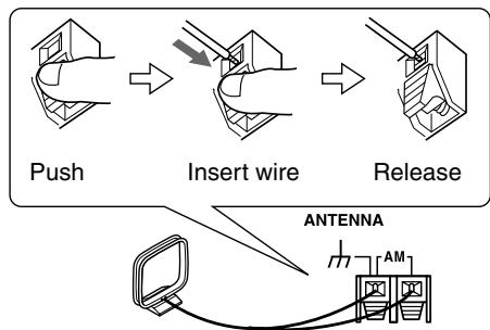
AM ANTENNA
These push terminals are for connecting an AM antenna.
⑦ AC INLET
The supplied power cord is connected here. The other end of the power cord should be connected to a suitable wall outlet.
18 GND screw
This screw is for connecting a turntable's ground wire.
19 PHONO IN
These analog audio inputs are for connecting a turntable.
BALANCE L/R INPUT
This balanced XLR input is for connecting a component with a stereo balanced XLR output. For a mono source, connect to the BALANCE L XLR.
③ CD IN
These analog audio inputs are for connecting a CD player's analog audio output.
12V TRIGGER OUT (A/B/C)
These outputs can be connected to the 12-volt trigger inputs on other components.
② TV/TAPE IN/OUT
These analog audio inputs and outputs are for connecting a TV or recorder with an analog audio input and output (cassette, Mini Disc, etc.).
24AUX 2 IN
This analog audio input is for connecting an analog audio output, such as an audio device, etc.
25 GAME IN
Here you can connect a game console, etc. Input jacks include S-Video, composite video, and analog audio.
CBL/SAT IN
Here you can connect a cable/satellite receiver, settop box, etc. Input jacks include S-Video, composite video, and analog audio.
VCR/DVR IN/OUT
Here you can connect a VCR or DVR (digital video recorder). Input and output jacks include S-Video, composite video, and analog audio.
DVD/BD IN
Here you can connect a DVD/BD player. Input jacks include S-Video, composite video, and analog audio. You can connect a DVD/BD player's 2-channel analog audio output.
29 MULTI CH input: FRONT L/R, CENTER, SUBWOOFER, SURR L/R, and SURR BACK L/R
This analog multichannel input is for connecting a component with a 5.1/7.1-channel analog audio output, such as a DVD player, DVD-Audio or Super Audio CD-capable player, or an MPEG decoder.
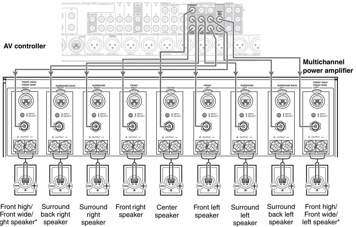
PRE OUT: FRONT L/R, CENTER, SURR L/R, SURR BACK L/R, and FRONT HIGH/WIDE L/R
These multichannel analog audio outputs can be connected to the analog audio input on a multichannel power amplifier.
PRE OUT: SW1, SW2
These analog audio outputs can be connected to a powered subwoofer. You can connect the powered subwoofer with each jacks respectively. Level and distance can be set individually for each output.
PRE OUT: ZONE 2, ZONE 3
These analog audio outputs can be connected to the line inputs on amplifiers in Zone 2 and Zone 3. The SW jacks can be connected to the inputs on powered subwoofoers in Zone 2 and Zone 3.
PRE OUT: FRONT L/R, CENTER, SUBWOOFER 1/2, SURR L/R, SURR BACK L/R, and FRONT HIGH/WIDE L/R
These balanced XLR outputs are for connecting a multichannel power amplifier and powered subwoofer.
The FRONT L/R and SURR BACK L/R outputs can be used with front speakers and surround back speakers, respectively, or used to bi-amp the front speakers. See "Bi-amping the Front Speakers" on page 21.
SIRIUS antenna
(North American models)
This jack is for connecting a SIRIUS Satellite Radio antenna, sold separately (see the separate SIRIUS instructions).
See pages 18 to 42 for connection information.
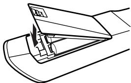
Installing the Batteries
1 To open the battery compartment, press the small lever and remove the cover.
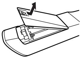
2 Insert the two supplied batteries (AA/R6) in accordance with the polarity diagram inside the battery compartment.

3 Replace the cover and push it shut.
Notes:
- If the remote controller doesn't work reliably, try replacing the batteries.
- Don't mix new and old batteries or different types of batteries.
- If you intend not to use the remote controller for a long time, remove the batteries to prevent damage from leakage or corrosion.
- Expired batteries should be removed as soon as possible to prevent damage from leakage or corrosion.
Aiming the Remote Controller
To use the remote controller, point it at the AV controller's remote control sensor, as shown below.
Transmission
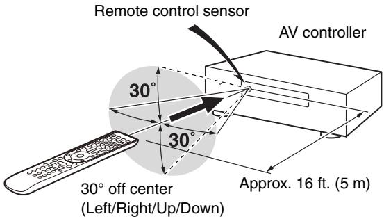
Received
Notes:
- The remote controller may not work reliably if the AV controller is subjected to bright light, such as direct sunlight or inverter-type fluorescent lights. Keep this in mind when installing.
- If another remote controller of the same type is used in the same room, or the AV controller is installed close to equipment that uses infrared rays, the remote controller may not work reliably.
- Don't put anything, such as a book, on the remote controller, because the buttons may be pressed inadvertently, thereby draining the batteries.
- The remote controller may not work reliably if the AV controller is installed in a rack behind colored glass doors. Keep this in mind when installing.
- The remote controller will not work if there's an obstacle between it and the AV controller's remote control sensor.
- When the remote control codes have been registered and you want to operate another component (page 135), or when you want to operate an Onkyo component without RI connection, point the remote controller at the other component to use it.
- When you want to operate an Onkyo component with RI connection or an R1HD-compatible component connected via HDMI (pages 137 and 138), point the remote controller at the AV controller's remote control sensor.
Controlling the AV Controller
To control the AV controller, press the [RECEIVER] button to select Receiver mode.
You can also use the remote controller to control your DVD/BD player, CD player, and other components.
See pages 133 to 147 for more details.
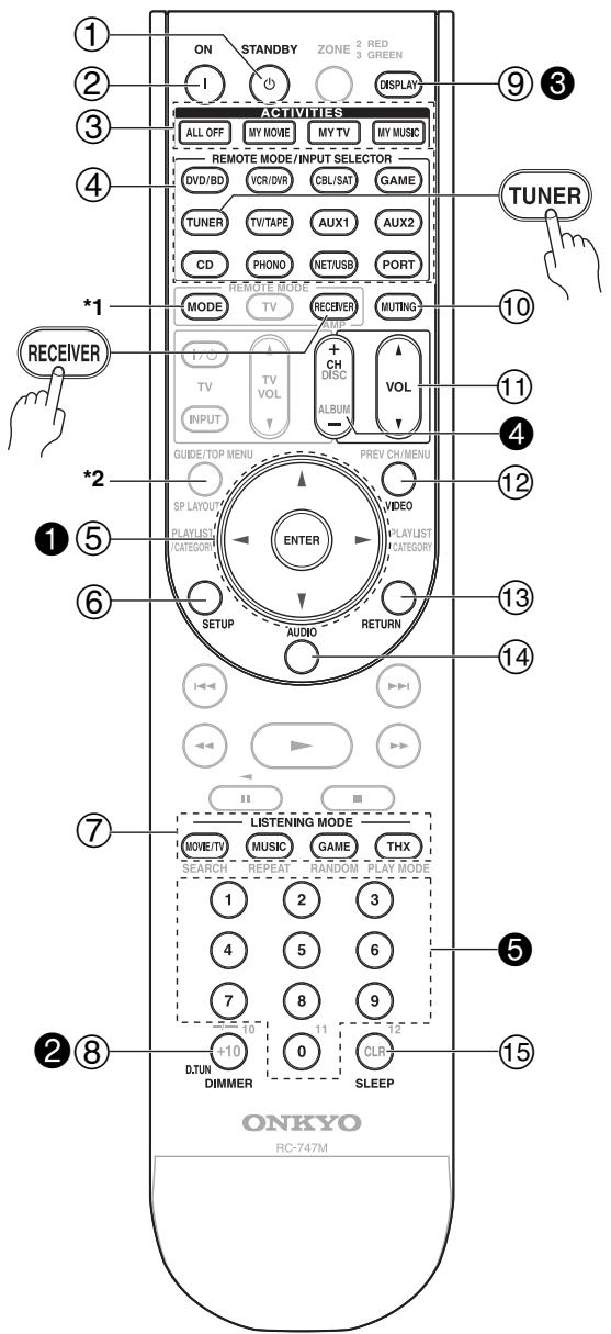
1 When you want to change the remote controller mode without changing the current input source, press the [MODE] button and within about eight seconds, press the REMOTE MODE button. Then, with the AV controller's remote controller, you can control the component corresponding to the button you pressed.
2 SP Layout button is not used for this model.
For detailed information, see the pages in parentheses.
① STANDBY button (43)
Sets the AV controller to Standby.
② ON button (43)
Turns on the AV controller.
③ ACTIVITIES buttons (65, 147)
Used with the MACRO function.
④ REMOTE MODE/INPUT SELECTOR buttons (62, 137 to 143)
Selects the remote controller modes and the input sources.
⑤ Arrow [▲]/[▼]/[▲]/[▶] and ENTER buttons
Used to select and adjust settings.
⑥ SETUP button
Used to change settings.
⑦ LISTENING MODE buttons (75)
Used to select the listening modes.
⑧ DIMMER button (64)
Adjusts the display brightness.
⑨ DISPLAY button (63)
Displays information about the current input source.
⑩ MUTING button (64)
Mutes or unmutes the AV controller.
① VOL [▲]/[▼] button (62)
Adjusts the volume of the AV controller regardless of the currently selected remote controller mode.
⑫VIDEO button (44, 48, 99)
Used to change video settings.
13 RETURN button
Returns to the previous display when changing settings.
⑭ AUDIO button (112)
Used to change audio settings.
When the "Audio TV Out" setting is set to "On" (page 108), this button is disabled.
⑮ SLEEP button (64)
Used with the Sleep function.
Controlling the tuner
To control the AV controller's tune, press the [TUNER] (or [RECEIVER]) button.
You can select AM or FM by pressing the [TUNER] button repeatedly.
Arrow [ ] / [ ] buttons
Used to tune into radio stations.
D.TUN button (67)
(TUNER remote mode only)
Selects the Direct tuning mode.
3 DISPLAY button
Displays information about the band, frequency, preset number, and so on.
CH + / - button (68)
Used to select radio presets.
Number buttons (67, 68)
Used to select radio stations directly in the Direct tuning mode. Also you can select a preset directly.
Note:
An Onkyo cassette recorder connected via RI can also be controlled in Receiver mode (see page 143).
Enjoying Home Theater
Thanks to the AV controller's superb capabilities, you can enjoy surround sound with a real sense of movement in your own home—just like being in a movie theater or concert hall. With DVDs you can enjoy DTS and Dolby Digital. With analog or digital TV, you can enjoy Dolby Pro Logic IIx, DTS Neo:6, or Onkyo's original DSP listening modes. You can also enjoy THX Surround EX (THX-certified THX speaker system recommended).
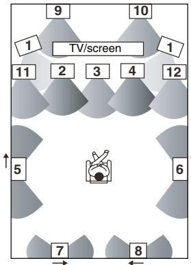
Front left and right speakers
These output the overall sound. Their role in a home theater is to provide a solid anchor for the sound image. They should be positioned facing the listener at about ear level, and equidistant from the TV. Angle them inward so as to create a triangle, with the listener at the apex.
Front high left and right speakers
These speakers are necessary to enjoy Dolby Pro Logic IIz Height, and Audyssey Dynamic Surround Expansion™. They significantly enhance the spatial experience. Position them at least 3.3 feet (100 cm) above the front left and right speakers (preferably as high as possible) and at an angle slightly wider than the front left and right speakers.
Front wide left and right speakers
These speakers are necessary to enjoy Audyssey Dynamic Surround Expansion™ (DSX). They significantly enhance the spatial experience. Position them well outside of the front left and right speakers. See also http://www.audyssey.com/technology/dsx.html about optimum speaker placement for Audyssey Dynamic Surround Expansion™.
Center speaker
This speaker enhances the front left and right speakers, making sound movements distinct and providing a full sound image. In movies it's used mainly for dialog. Position it close to your TV facing forward at about ear level, or at the same height as the front left and right speakers.
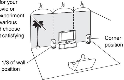
Subwoofer
The subwoofer handles the bass sounds of the LFE (Low-Frequency Effects) channel. The volume and quality of the bass output from your subwoofer will depend on its position, the shape of your listening room, and your listening position. In general, a good bass sound can be obtained by installing the subwoofer in a front corner, or at one-third the width of the wall, as shown.
Tip: To find the best position for your subwoofer, while playing a movie or some music with good bass, experiment by placing your subwoofer at various positions within the room, and choose the one that provides the most satisfying results.
Surround back left and right speakers
These speakers are necessary to enjoy Dolby Digital EX, DTS-ES Matrix, DTS-ES Discrete, THX Surround EX, etc. They enhance the realism of surround sound and improve sound localization behind the listener. Position them behind the listener about 2 to 3 feet (60 to 100cm ) above ear level.
Surround left and right speakers
These speakers are used for precise sound positioning and to add realistic ambience.
Position them at the sides of the listener, or slightly behind, about 2 to 3 feet (60 to 100cm ) above ear level. Ideally they should be equidistant from the listener.
Connecting Your Speakers
The AV controller is designed to be used with a separate multichannel power amplifier. You connect the AV controller's PRE OUT jacks to the amplifier's inputs, and connect your speakers to the amplifier's speakers terminals. Speaker settings such as crossover frequency and distance are set on the AV controller.
Speaker Configuration
For 9.2-channel surround-sound playback, you need nine speakers and two powered subwoofer.
The following table indicates the channels you should use depending on the number of speakers that you have.
| Number of speakers: | 2 | 3 | 4 | 5 | 6 | 7 | 7 | 7 | 8 | 8 | 9 | 9 |
| Front left | ✓ | ✓ | ✓ | ✓ | ✓ | ✓ | ✓ | ✓ | ✓ | ✓ | ✓ | ✓ |
| Front right | ✓ | ✓ | ✓ | ✓ | ✓ | ✓ | ✓ | ✓ | ✓ | ✓ | ✓ | ✓ |
| Center | ✓ | ✓ | ✓ | ✓ | ✓ | ✓ | ✓ | ✓ | ✓ | ✓ | ||
| Surround left | ✓ | ✓ | ✓ | ✓ | ✓ | ✓ | ✓ | ✓ | ✓ | ✓ | ||
| Surround right | ✓ | ✓ | ✓ | ✓ | ✓ | ✓ | ✓ | ✓ | ✓ | ✓ | ||
| Surround back* | ✓ | ✓ | ✓ | |||||||||
| Surround back left | ✓ | ✓ | ✓ | |||||||||
| Surround back right | ✓ | ✓ | ✓ | |||||||||
| Front high left | ✓ | ✓ | ✓ | |||||||||
| Front high right | ✓ | ✓ | ✓ | |||||||||
| Front wide left | ✓ | ✓ | ✓ | |||||||||
| Front wide right | ✓ | ✓ | ✓ |
- If you're using only one surround back speaker, connect it to the SURR BACK L output.
No matter how many speakers you use, two powered subwooers are recommended for a really powerful and solid bass. To get the best from your surround sound system, you need to set the speaker settings. You can do this automatically (see page 56) or manually (see page 90).
Note:
Front high and front wide speakers produce no sound at the same time.
Connecting Powered Subwoofer
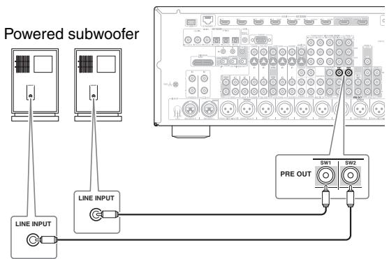
Using a suitable cable, connect the AV controller's PRE OUT: SW1, SW2 to an input on your powered subwoofer, as shown. If your subwoofer is unpowered and you're using an external amplifier, connect the PRE OUT: SW1, SW2 to an input on the amp.
You can connect the powered subwoofer with each jacks respectively. Level and distance can be set individually for each output. If you use one subwoofer, connect it to PRE OUT: SW1.
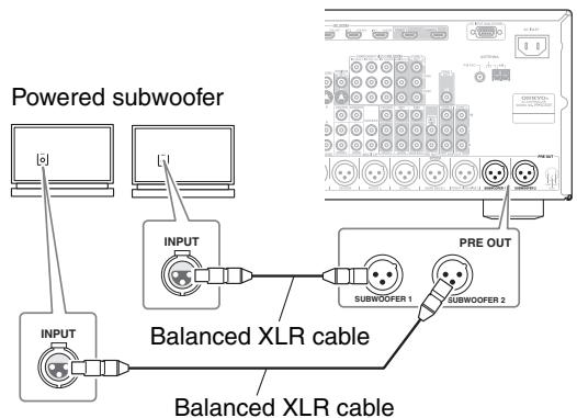
You can also connect a powered subwoofer to the AV controller's balanced SUBWOOFER 1 PRE OUT XLR, SUBWOOFER 2 PRE OUT XLR jack by using a balanced XLR cable.
You can connect the powered subwoofer with each jacks respectively. Level and distance can be set individually for each output. If you use one subwoofer, connect it to SUBWOOFER 1 PRE OUT XLR.
Using Dipole Speakers
You can use dipole speakers for the surround left and right, surround back left and right speakers. Dipole speakers output the same sound in two directions.
Dipole speakers typically have an arrow printed on them to indicate how they should be positioned. The surround left and right dipole speakers should be positioned so that their arrows point toward the TV/screen, while the surround back left and right and front high left and right and front wide left and right dipole speakers should be positioned so that their arrows point toward each other, as shown.
Dipole speakers
- Subwoofoers
- Front left speaker
- Center speaker
- Front right speaker
- Surround left speaker
- Surround right speaker
- Surround back left speaker
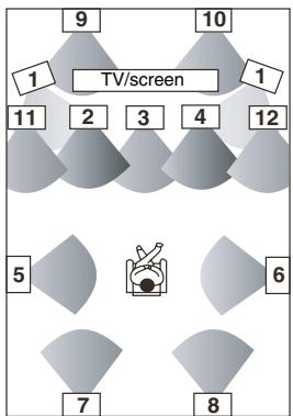
Normal speakers
- Surround back right speaker
- Front high left speaker
- Front high right speaker
11.Front wide left speaker
12.Front wide right speaker
Connecting a Power Amplifier with RCA Inputs
You can connect the AV controller to a multichannel power amplifier with RCA input jacks by using a multichannel RCA audio cable or several stereo RCA audio cables.
See your multichannel power amplifier's instruction manual for more information on connecting speakers.
Note:
- Specify crossover frequency for the channel that you want to output in "Speaker Configuration" (see page 90).
Connecting a Power Amplifier with XLR Inputs
You can connect the AV controller to a multichannel power amplifier with balanced XLR input jacks by using several XLR audio cables.
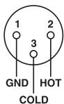
The AV controller's balanced PRE OUT XLR jacks are wired as shown.
See your multichannel power amplifier's instruction manual for more information on connecting speakers.
AV controller
Note:
- Specify crossover frequency for the channel that you want to output in "Speaker Configuration" (see page 90).
Bi-amping the Front Speakers
The FRONT L/R and SURR BACK L/R outputs can be used with front speakers and surround back speakers, respectively, or bi-amped to provide separate tweeter and woofer feeds for a pair of front speakers that support bi-amping, providing improved bass and treble performance.
- When bi-amping is used, the AV controller is able to feed up to 7.2 speakers in the main room.
- For bi-amping, the FRONT L/R outputs feed the front speakers' woofer terminals. And the SURR BACK L/R outputs feed the front speakers' tweeter terminals.
- Once you've completed the bi-amping connections shown below and turned on the AV controller, you must set the "Speakers Type(Front)" setting to "Bi-Amp" to enable bi-amping (see page 53).
Important:
- When making the bi-amping connections, be sure to remove the jumper bars that link the speakers' tweeter (high) and woofer (low) terminals.
- Bi-amping can only be used with speakers that support bi-amping. Refer to your speaker manual.
See your multichannel power amplifier's instruction manual for more information on connecting speakers.
Connecting Antenna
This section explains how to connect the supplied indoor FM antenna and AM loop antenna, and how to connect commercially available outdoor FM and AM antennas. The AV controller won't pick up any radio signals without any antenna connected, so you must connect the antenna to use the tuner.
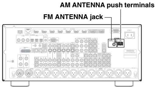
Connecting the Indoor FM Antenna
The supplied indoor FM antenna is for indoor use only.
1 Attach the FM antenna, as shown. (North American models)
(European and Asian models)
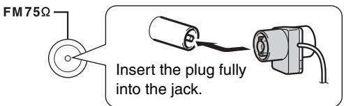
Once your AV controller is ready for use, you'll need to tune into an FM radio station and adjust the position of the FM antenna to achieve the best possible reception.
2 Use thumbtacks or something similar to fix the FM antenna into position.
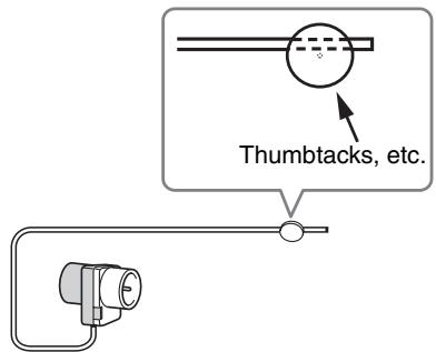
Caution: Be careful that you don't injure yourself when using thumbtacks.
If you cannot achieve good reception with the supplied indoor FM antenna, try a commercially available outdoor FM antenna instead (see page 23).
Connecting the AM Loop Antenna
The supplied indoor AM loop antenna is for indoor use only.
1 Assemble the AM loop antenna, inserting the tabs into the base, as shown.
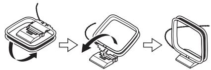
2 Connect both wires of the AM loop antenna to the AM antenna push terminals, as shown.
(The antenna's wires are not polarity sensitive, so they can be connected either way around.)
Make sure that the wires are attached securely and that the push terminals are gripping the bare wires, not the insulation.
Once your AV controller is ready for use, you'll need to tune into an AM radio station and adjust the position of the AM antenna to achieve the best possible reception.
Keep the antenna as far away as possible from your AV controller, TV, speaker cables, and power cords.
If you cannot achieve good reception with the supplied indoor AM loop antenna, try using it with a commercially available outdoor AM antenna (see page 23).
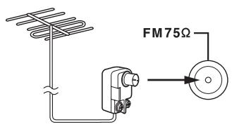
Connecting an Outdoor FM Antenna
If you cannot achieve good reception with the supplied indoor FM antenna, try a commercially available outdoor FM antenna instead.
Notes:
- Outdoor FM antennas work best outside, but usable results can sometimes be obtained when installed in an attic or loft.
- For best results, install the outdoor FM antenna well away from tall buildings, preferably with a clear line of sight to your local FM transmitter.
- Outdoor antenna should be located away from possible noise sources, such as neon signs, busy roads, etc.
- For safety reasons, outdoor antenna should be situated well away from power lines and other high-voltage equipment.
- Outdoor antenna must be grounded in accordance with local regulations to prevent electrical shock hazards.
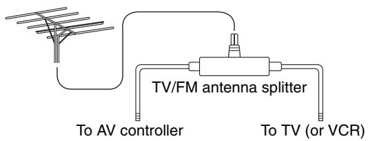
Using a TV/FM Antenna Splitter
It's best not to use the same antenna for both FM and TV reception, as this can cause interference problems. If circumstances demand it, use a TV/FM antenna splitter, as shown.
Connecting an Outdoor AM Antenna
If good reception cannot be achieved using the supplied AM loop antenna, an outdoor AM antenna can be used in addition to the loop antenna, as shown.
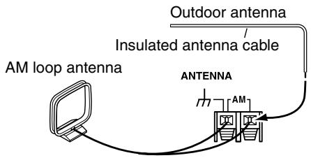
Outdoor AM antennas work best when installed outside horizontally, but good results can sometimes be obtained indoors by mounting horizontally above a window. Note that the outdoor antenna should be right connected.
Outdoor antenna must be grounded in accordance with local regulations to prevent electrical shock hazards.
About AV Connections
- Before making any AV connections, read the manuals supplied with your other AV components.
- Don't connect the power cord until you've completed and double-checked all AV connections.
Optical Digital Jacks
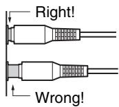
The AV controller's optical digital jacks have shutter-type covers that open when an optical plug is inserted and close when it's removed. Push plugs in all the way.
Caution:
To prevent shutter damage, hold the optical plug straight when inserting and removing.
AV Connection Color Coding
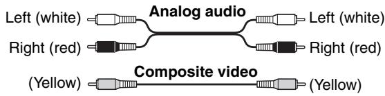
RCA-type AV connections are usually color-coded: red, white, and yellow. Use red plugs to connect right-channel audio inputs and outputs (typically labeled "R"). Use white plugs to connect left-channel audio inputs and outputs (typically labeled "L"). And use yellow plugs to connect composite video inputs and outputs.
- Push plugs in all the way to make good connections (loose connections can cause noise or malfunctions).
- To prevent interference, keep audio and video cables away from power cords and speaker cables.
AV Cables & Jacks
Video / Audio
| Cable | Jack | Description | |
| HDMI | HDMI | HDMI connections can carry uncompressed standard- or high-definition digital video and audio and offer the best picture and sound quality. | |
Video
| Component video cable | Y PB/CB PR/CR | Y CB/PB CR/PR | Component video separates the luminance (Y) and color difference signals (PR, PB), providing the best picture quality (some TV manufacturers label their component video sockets slightly differently). |
| S-Video cable | s | S-Video separates the luminance and color signals and provides better picture quality than composite video. | |
| Composite video cable | v | Composite video is commonly used on TVs, VCRs, and other video equipment. |
Audio
| Optical digital audio cable | OPTICAL | Offers the best sound quality and allows you to enjoy surround sound (e.g., Dolby Digital, DTS). The audio quality is the same as for coaxial. | |
| Coaxial digital audio cable | COAXIAL | Offers the best sound quality and allows you to enjoy surround sound (e.g., Dolby Digital, DTS). The audio quality is the same as for optical. | |
| Balanced XLR cable | INPUT PREOUT | This cable carries analog audio. Balanced XLR cables are used for better noise immunity and longer cable runs. | |
| Analog audio cable (RCA) | L R | This cable carries analog audio. It's the most common connection format for analog audio, and can be found on virtually all AV components. | |
| Multichannel analog audio cable (RCA) | CENTER SURBACK | This cable carries multichannel analog audio and is typically used to connect DVD players with a 7.1-channel analog audio output. Several standard analog audio cables can be used instead of a multichannel cable. |
The AV controller does not support SCART plugs.
Connecting Components with HDMI
About HDMI
Designed to meet the increased demands of digital TV, HDMI (High Definition Multimedia Interface) is a new digital interface standard for connecting TVs, projectors, DVD/BD players, set-top boxes, and other video components. Until now, several separate video and audio cables have been required to connect AV components. With HDMI, a single cable can carry control signals, digital video, and up to eight channels of digital audio (2-channel PCM, multichannel digital audio, and multichannel PCM).
The HDMI video stream (i.e., video signal) is compatible with DVI (Digital Visual Interface) ^1 , so TVs and displays with a DVI input can be connected by using an HDMI-to-DVI adapter cable. (This may not work with some TVs and displays, resulting in no picture.)
The AV controller uses HDCP (High-bandwidth Digital Content Protection) ^2 , so only HDCP-compatible components can display the picture.
The AV controller's HDMI interface is based on the following standard:
x.v.Color, Deep Color, Lip Sync, DTS-HD Master Audio, DTS-HD High Resolution Audio, Dolby TrueHD, Dolby Digital Plus, DSD, and Multichannel PCM
Supported Audio Formats
2-channel linear PCM (32-192 kHz, 16/20/24 bit)
- Multichannel linear PCM (up to 7.1 ch, 32–192 kHz, 16/20/24 bit)
- Bitstream (DSD, Dolby Digital, Dolby Digital Plus, Dolby TrueHD, DTS, DTS Express, DTS-HD High Resolution Audio, DTS-HD Master Audio)
Your DVD/BD players must also support HDMI output of the above audio formats.
Onkyo RHD for System Control
RIHD, which stands for Remote Interactive over HDMI, is the name of the system control function found on Onkyo components. The AV controller can be used with CEC (Consumer Electronics Control), which allows system control over HDMI and is part of the HDMI standard. CEC provides interoperability between various components, however, operation with components other than RIHD -compatible components cannot be guaranteed.
- Set "HDMI Control (RIHD)" to "On" (page 109).
- See "Controlling a TV" (page 137) and "Controlling a DVD Player or DVD Recorder" (page 138) for operation.
Notes:
- Do not connect the R1HD-compatible component more than the following number to the HDMI input terminal so that the linked operations work properly.
a. DVD/BD player is up to three.
b. DVD/BD recorder is up to three.
c. Cable/Satellite Set-top box is up to four.
- Do not connect the AV controller to the other AV controller /AV amplifier via HDMI.
- When the R1HD-compatible component more than the above-mentioned is connected, the linked operations are not guaranteed.
- The R1HD control does not support HDMI OUT SUB. Use HDMI OUT MAIN instead.
About Copyright Protection
The AV controller supports HDCP (High-bandwidth Digital Content Protection) ^2 , a copy-protection system for digital video signals. Other devices connected to the AV controller via HDMI must also support HDCP.
1 DVI (Digital Visual Interface): The digital display interface standard set by the DDWG3 in 1999.
2 HDCP (High-bandwidth Digital Content Protection): The video encryption technology developed by Intel for HDMI/DVI. It's designed to protect video content and requires a HDCP-compatible device to display the encrypted video.
3 DDWG (Digital Display Working Group): Lead by Intel, Compaq, Fujitsu, Hewlett Packard, IBM, NEC, and Silicon Image, this open industry group's objective is to address the industry's requirements for a digital connectivity specification for high-performance PCs and digital displays.
Making HDMI Connections
Step 1:
Use HDMI cables to connect the AV controller's HDMI jacks to your HDMI-compatible DVD/BD player, TV, projector, and so on.
Step 2:
Assign each HDMI IN to an input selector in the HDMI Input Setup (see page 49).
Video Signals
Digital video signals received by the HDMI IN jacks are normally output by the HDMI MAIN OUT and SUB OUT for display on your TV. Composite video, S-Video, and component video sources can be upconverted for the HDMI output. See "Video Connection Formats" on page 28 for more information.
Audio Signals
Digital audio signals received by the HDMI IN jacks are output by the speakers and headphones connected to the AV controller. Normally, they are not output by the HDMI outputs, unless the "Audio TV Out" setting is set to "On" (see page 108).

To listen to audio received by the HDMI IN jacks through your TV's speakers:
- Set the "TV Control" setting to "On" (see page 109) for an RUHD-compatible TV.
- Set the "Audio TV Out" setting to "On" (see page 108) when the TV is not compatible with R1HD or the "TV Control" setting to "Off".
- Set your DVD/BD player's HDMI audio output setting to PCM.
Notes:
- The HDMI video stream is compatible with DVI (Digital Visual Interface), so TVs and displays with a DVI input can be connected by using an HDMI-to-DVI adapter cable. (Note that DVI connections only carry video, so you'll need to make a separate connection for audio.) However, reliable operation with such an adapter is not guaranteed. In addition, video signals from a PC are not guaranteed.
- When listening to an HDMI component through the AV controller, set the HDMI component so that its video can be seen on the TV screen (on the TV, select the input of the HDMI component connected to the AV controller). If the TV power is off or the TV is set to another input source, this may result in no sound from the AV controller or the sound may be cut off.
- When the "Audio TV Out" setting is set to "On" (see page 108) to hear from your TV's speakers, by controlling the AV controller's volume, the sound will be output from the AV controller's speakers, too. When the "TV Control" setting is set to "On" to hear from speakers of R1HD-compatible TV, by controlling the AV controller's volume, the AV controller's speakers will produce sound while the TV's speakers are muted. To stop the AV controller's speakers producing sound, change the settings, change your TV's settings, or turn down the AV controller's volume.
- The HDMI audio signal (sampling rate, bit length, etc.) may be restricted by the connected source component. If the picture is poor or there's no sound from a component connected via HDMI, check its setup. Refer to the connected component's instruction manual for details.
Connecting Both Audio & Video
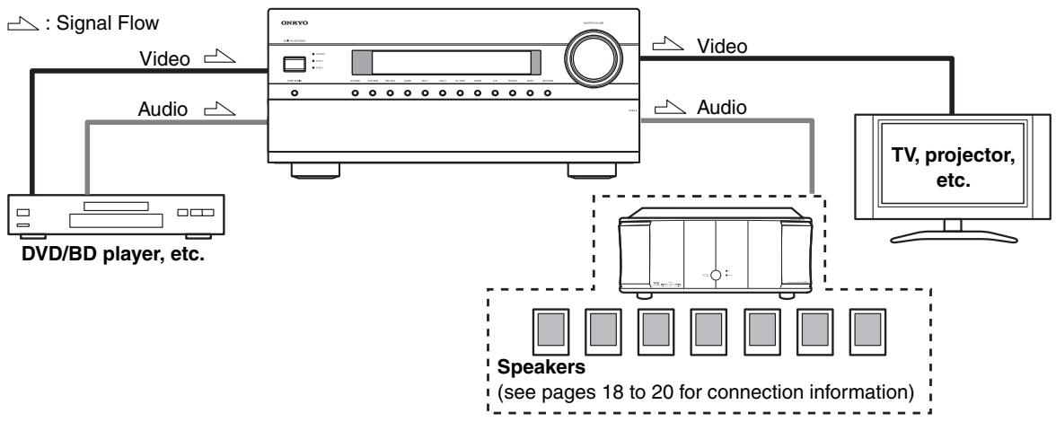
By connecting both the audio and video outputs of your DVD/BD player and other AV components to the AV controller, you can select both the audio and video simultaneously simply by selecting the appropriate input source on the AV controller.
Which Connections Should I Use?
The AV controller supports several connection formats for compatibility with a wide range of AV equipment. The format you choose will depend on the formats supported by your other components. Use the following sections as a guide.
Video Connection Formats
Video equipment can be connected to the AV controller by using any one of the following video connection formats: composite video, S-Video, component video, or HDMI, the latter offering the best picture quality.
The AV controller can upconvert and downconvert between video formats, depending on the "Monitor Out" setting, which generally determines whether video signals are upconverted for the component video output or the HDMI output.
For optimal video performance, THX recommends that video signals pass through the system without upconversion (e.g., component video input through to component video output).
It is also recommended that you press the [VCR/DVR] and [RETURN] buttons on the AV controller at the same time. Select "Skip" in the "VideoProcessor" setting by pressing the [RETURN] button repeatedly on the display. To reset back to the original setting, press the same button at the same time.
■ "Monitor Out" Setting Set to "HDMI Main" or "HDMI Sub"
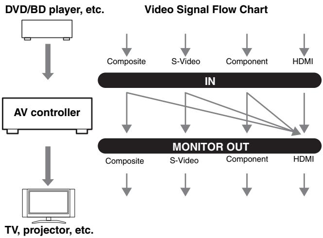
With the "Monitor Out" setting set to "HDMI Main" or "HDMI Sub" (see page 47), video input signals flow through the AV controller as shown, with composite video, S-Video, and component video sources all being upconverted for the HDMI output. Use the "HDMI Main" or "HDMI Sub" setting if you connect the AV controller's HDMI OUT MAIN or HDMI OUT SUB, respectively, to your TV.
The composite video, S-Video, and component video outputs pass through their respective input signals as they are.
Note:
If not connected to the same output you have selected in the "Monitor Out" setting, the "Monitor Out" setting will be automatically switched to "Analog" (see page 47). In this case, the set
ting of the output resolution will be that for HDMI output (see page 47). However, it will be switched to "1080i" when "1080p" is selected, and to "Through" when "Auto" is selected.
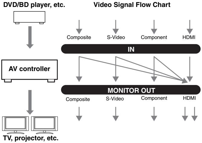
■ "Monitor Out" Setting Set to "Both", "Both(Main)" or "Both(Sub)"
With the "Monitor Out" setting set to "Both", "Both(Main)" or "Both(Sub)" (see page 47), video input signals flow through the AV controller as shown, with composite video, S-Video, and component video sources all being upconverted for both HDMI outputs. Use the "Both", "Both(Main)" or "Both(Sub)" setting if you connect the AV controller's HDMI OUT MAIN and HDMI OUT SUB to your TVs.
The composite video, S-Video, and component video outputs pass through their respective input signals as they are.
Both: Video signals are output from both HDMI outputs at the resolution supported by both TVs. You cannot select "Resolution" setting. The picture adjust setting will be that for "HDMI Main".
Both (Main): Video signals are output from both
HDMI outputs but HDMI OUT MAIN will become a priority; depending on the resolution, video signals may not be output from HDMI OUT SUB.
Both (Sub): Video signals are output from both HDMI outputs but HDMI OUT SUB will become a priority; depending on the resolution, video signals may not be output from HDMI OUT MAIN.
Note:
The "Monitor Out" setting will be automatically switched to "Analog" (see page 47) if not connected to both outputs when "Both" is selected or if not connected to a priority output when "Both(Main)" or "Both(Sub)" is selected.
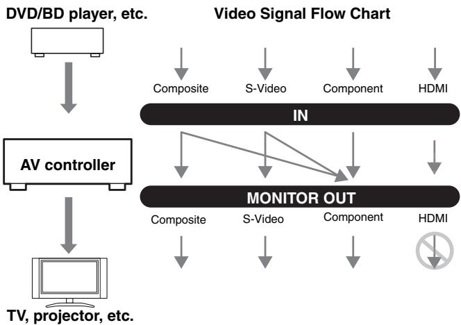
“Monitor Out” Setting Set to “Analog”
With the "Monitor Out" setting set to "Analog" (see page 47), video input signals flow through the AV controller as shown, with composite video and S-Video sources being upconverted for the component video output. Use this setting if you connect the AV controller's COMPO-NENT VIDEO MONITOR OUT to your TV.
Composite video is upconverted to S-Video and S-Video is downconverted to composite video. Note that these conversions only apply to the MONITOR OUT V and S outputs, not the VCR/DVR OUT V and S outputs.
The composite video, S-Video, and component video outputs pass through their respective input signals as they are.
This signal flow also applies when the "Resolution" setting is set to "Through" (see page 47).
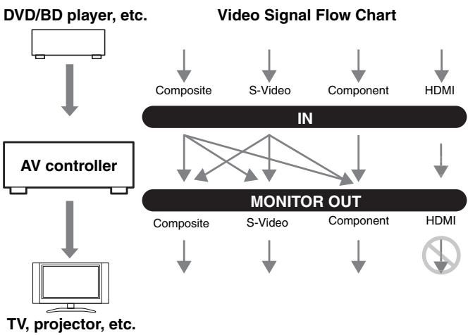
Video Signal Flow and the Resolution Setting
When the "Monitor Out" setting is set to "Analog" (see page 47), if the "Resolution" setting is set to anything other than "Through" (see page 47), the video signal flow will be as shown here, with composite video and S-Video sources being upconverted for the component video output.
The composite video, S-Video, and component video outputs pass through their respective analog input signals as they are. HDMI input signals are not output.
Audio Connection Formats
Audio equipment can be connected to the AV controller by using any of the following audio connection formats: analog, optical, coaxial, analog multichannel, or HDMI.
When choosing a connection format, bear in mind that the AV controller does not convert digital input signals for analog line outputs and vice versa. For example, audio signals connected to an optical or coaxial digital input are not output by the analog TV/TAPE OUT.
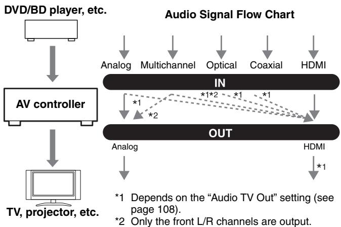
If signals are present at more than one input, the inputs will be selected automatically in the following order of priority: HDMI, digital, analog.
Connecting a TV or Projector
See "Connecting Components with HDMI" on page 25 for HDMI connection information.
Step 1: Video Connection
Choose a video connection that matches your TV (A, B, or C), and then make the connection.
Step 2: Audio Connection
Choose an audio connection that matches your TV (a, b, or c), and then make the connection.
- With connection a, you can listen to and record audio from your TV or listen in Zone 2 or Zone 3.
- To enjoy Dolby Digital and DTS, use connection b or c. (To record or listen in Zone 2 or Zone 3 as well, use a and b, or a and c.)
| Connection | AV controller | Signal flow | TV, projector, etc. |
| A | COMPONENT Video MONITOR OUT | ⇒ | Component video input |
| B | MONITOR OUT S | ⇒ | S-Video input |
| C | MONITOR OUT V | ⇒ | Composite video input |
| a | TV/TAPE IN L/R | ← | Analog audio L/R output |
| b | DIGITAL COAXIAL IN 2 (VCR/DVR) | ← | Digital coaxial output |
| c | DIGITAL OPTICAL IN 2 (TV/TAPE) | ← | Digital optical output |
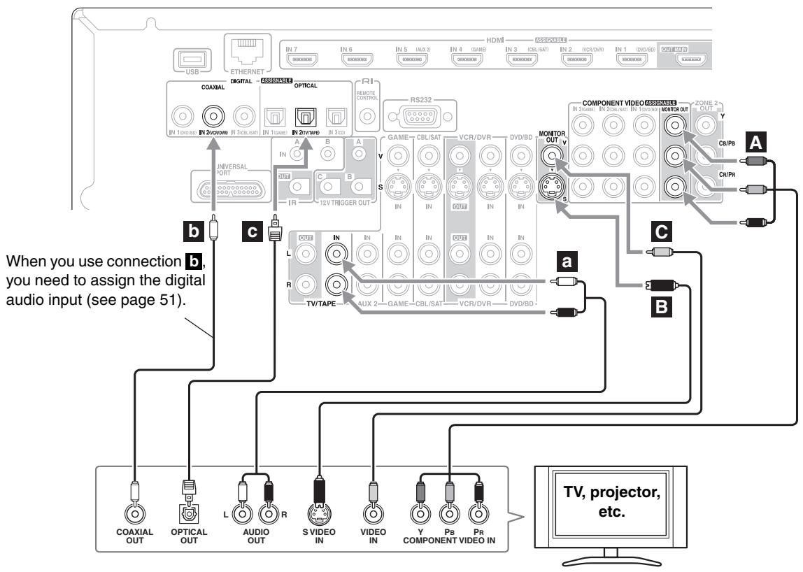

If your TV has no audio outputs, connect an audio output from your VCR or cable or satellite receiver to the AV controller and use its tuner to listen to TV programs through the AV controller (see pages 34 and 36).
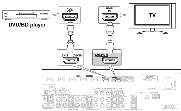
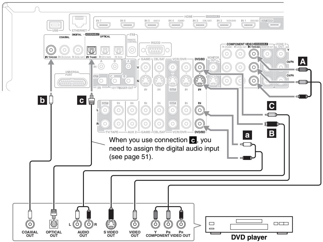
Connecting a DVD Player
See "Connecting Components with HDMI" on page 25 for HDMI connection information.
Step 1: Video Connection
Choose a video connection that matches your DVD player (A, B, or C), and then make the connection.
You must connect the AV controller to your TV via the same type of connection.
Step 2: Audio Connection
Choose an audio connection that matches your DVD player (a, b, or c), and then make the connection.
- With connection a, you can listen to and record audio from your DVD player or listen in Zone 2 or Zone 3.
- To enjoy Dolby Digital and DTS, use connection b or c. (To record or listen in Zone 2 or Zone 3 as well, use a and b, or a and c.)
- If your DVD player has main left and right outputs and multichannel left and right outputs, be sure to use the main left and right outputs for connection a.
| Connection | AV controller | Signal flow | DVD player |
| A | COMPONENT Video IN 1 (DVD/BD) | ← | Component video output |
| B | DVD/BD IN S | ← | S-Video output |
| C | DVD/BD IN V | ← | Composite video output |
| a | DVD/BD IN L/R | ← | Analog audio L/R output |
| b | DIGITAL COAXIAL IN 1 (DVD/BD) | ← | Digital coaxial output |
| c | DIGITAL OPTICAL IN 1 (GAME) | ← | Digital optical output |
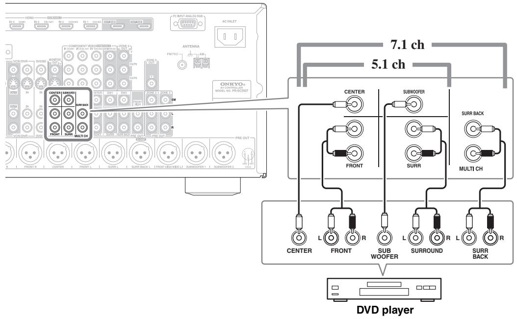
Hooking Up the Multichannel Input
If your DVD player supports multichannel audio formats such as DVD-Audio and Super Audio CD, and it has a multichannel analog audio output, you can connect it to the AV controller's multichannel input.
Use a multichannel analog audio cable, or several normal audio cables, to connect the AV controller's MULTI CH: FRONT L/R, CENTER, SURR L/R, SURR BACK L/R, and SUBWOOFER jacks to the 7.1-channel analog audio output on your DVD player. If your DVD player has a 5.1-channel analog audio output, don't connect anything to the AV controller's SURR BACK L/R jacks.
Before using the multichannel input, you must assign it to an input selector. See "Analog Audio Input Setup" on page 52. To select the multichannel input, see "Audio Selector" on page 114. To adjust the subwoofer sensitivity for the multichannel input, see "Subwoofer Input Sensitivity" on page 88.
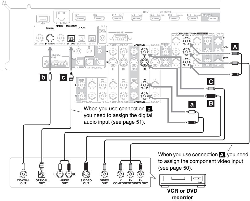
Connecting a VCR or DVD Recorder for Playback

With this hookup, you can use your VCR's tuner to listen to your favorite TV programs via the AV controller, useful if your TV has no audio outputs.
Step 1: Video Connection
Choose a video connection that matches your VCR or DVD recorder (A, B, or C), and then make the connection. You must connect the AV controller to your TV via the same type of connection.
Step 2: Audio Connection
Choose an audio connection that matches your VCR or DVD recorder (a, b, or c), and then make the connection.
- With connection a, you can listen to the VCR or DVD recorder in Zone 2 or Zone 3.
- To enjoy Dolby Digital and DTS, use connection b or c. (To listen in Zone 2 or Zone 3 as well, use a and b, or a and c.)
| Connection | AV controller | Signal flow | VCR or DVD recorder |
| A | COMPONENT Video IN 2 (CBL/SAT) | ← | Component video output |
| B | VCR/DVR IN S | ← | S-Video output |
| C | VCR/DVR IN V | ← | Composite video output |
| a | VCR/DVR IN L/R | ← | Analog audio L/R output |
| b | DIGITAL COAXIAL IN 2 (VCR/DVR) | ← | Digital coaxial output |
| c | DIGITAL OPTICAL IN 1 (GAME) | ← | Digital optical output |
Connecting a VCR or DVD Recorder for Recording
Step 1: Video Connection
Choose a video connection that matches your VCR or DVD recorder (A or B), and then make the connection. The video source to be recorded must be connected to the AV controller via the same type of connection.
Step 2: Audio Connection
Make the audio connection a.
| Connection | AV controller | Signal flow | VCR or DVD recorder |
| A | VCR/DVR OUT S | ⇒ | S-Video input |
| B | VCR/DVR OUT V | ⇒ | Composite video input |
| a | VCR/DVR OUT L/R | ⇒ | Analog audio L/R input |
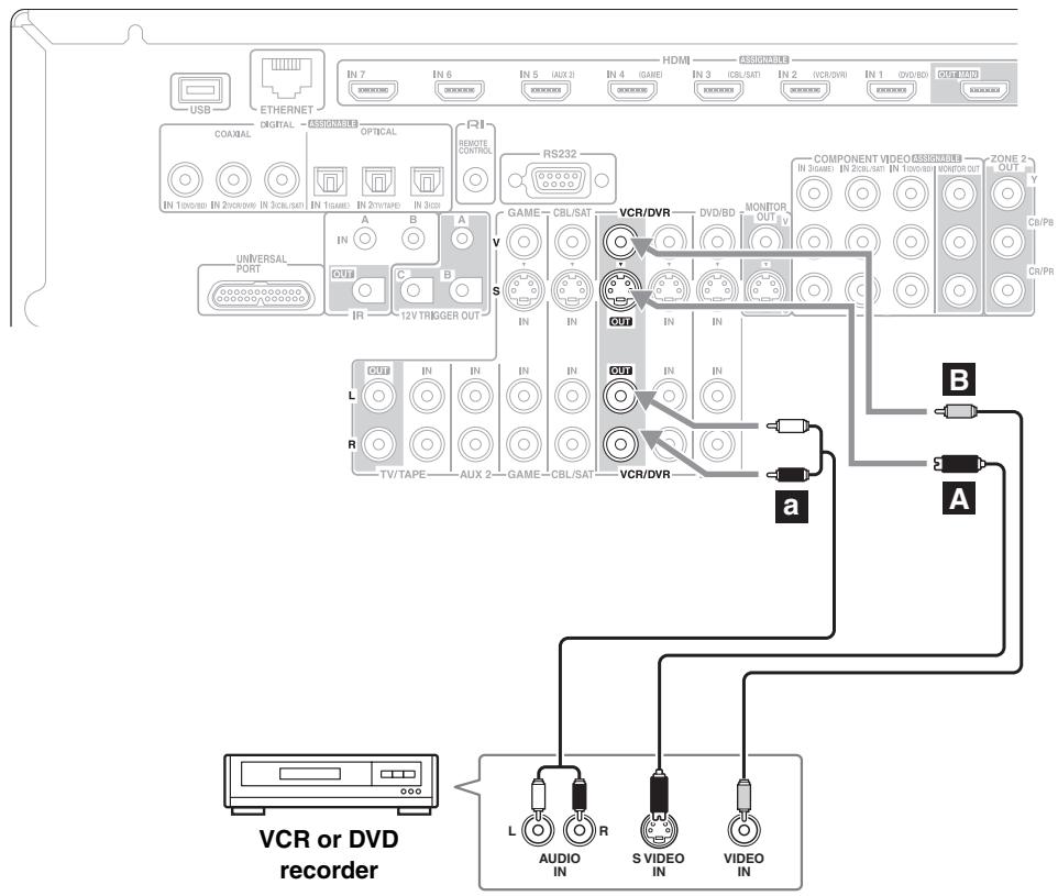
Notes:
- The AV controller must be turned on for recording. Recording is not possible while it's in Standby mode.
- If you want to record directly from your TV or playback VCR to the recording VCR without going through the AV controller, connect the TV/VCR's audio and video outputs directly to the recording VCR's audio and video inputs. See the manuals supplied with your TV and VCR for details.
- Video signals connected to composite video inputs can only be recorded via composite video outputs. If your TV/VCR is connected to a composite video input, the recording VCR must be connected to a composite video output. Similarly, video signals connected to S-Video inputs can only be recorded via S-Video outputs. If your TV/VCR is connected to an S-Video input, the recording VCR must be connected to an S-Video output.
- Sources connected to a digital input cannot be recorded. Only analog inputs can be recorded.
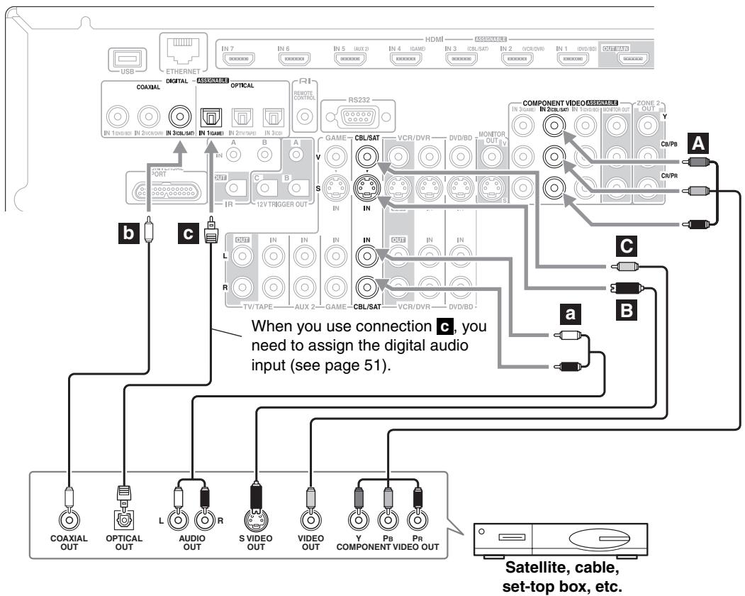
Connecting a Satellite, Cable, Terrestrial Set-top box, or Other Video Source

With this hookup, you can use your satellite or cable receiver to listen to your favorite TV programs via the AV controller, useful if your TV has no audio outputs.
Step 1: Video Connection
Choose a video connection that matches the video source (A, B, or C), and then make the connection. You must connect the AV controller to your TV via the same type of connection.
Step 2: Audio Connection
Choose an audio connection that matches the video source (a, b, or c), and then make the connection.
- With connection a, you can listen to and record audio from the video source or listen in Zone 2 or Zone 3.
- To enjoy Dolby Digital and DTS, use connection b or c. (To record or listen in Zone 2 or Zone 3 as well, use a and b, or a and c.)
| Connection | AV controller | Signal flow | Video source |
| A | COMPONENT Video IN 2 (CBL/SAT) | ← | Component video output |
| B | CBL/SAT IN S | ← | S-Video output |
| C | CBL/SAT IN V | ← | Composite video output |
| a | CBL/SAT IN L/R | ← | Analog audio L/R output |
| b | DIGITAL COAXIAL IN 3 (CBL/SAT) | ← | Digital coaxial output |
| c | DIGITAL OPTICAL IN 1 (GAME) | ← | Digital optical output |
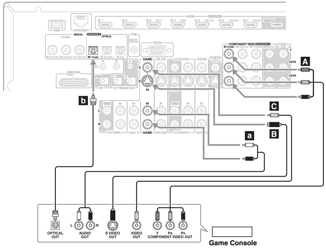
Connecting a Game Console
Step 1: Video Connection
Choose a video connection that matches your game console (A, B, or C), and then make the connection. You must connect the AV controller to your TV with the same type of connection.
Step 2: Audio Connection
Choose an audio connection that matches your game console (a or b), and then make the connection.
- With connection a, you can listen to and record audio from your game console or listen in Zone 2 or Zone 3.
- To enjoy Dolby Digital and DTS, use connection b. (To record or listen in Zone 2 or Zone 3 as well, use a and b.)
| Connection | AV controller | Signal flow | Game console |
| A | COMPONENT Video IN 3 (GAME) | ← | Component video output |
| B | GAME IN S | ← | S-Video output |
| C | GAME IN V | ← | Composite video output |
| a | GAME IN L/R | ← | Analog audio L/R output |
| b | DIGITAL OPTICAL IN 1 (GAME) | ← | Digital optical output |
Connecting a Camcorder or Other Device
Step 1: Video Connection
Make the connection A.
Step 2: Audio Connection
Choose an audio connection that matches your camcorder (a or b), and then make the connection.
| Connection | AV controller | Signal flow | Camcorder etc. |
| A | AUX1 INPUT VIDEO | ← | Composite video output |
| a | AUX1 INPUT L-AUDIO-R | ← | Analog audio L/R output |
| b | AUX1 INPUT DIGITAL | ← | Digital optical output |
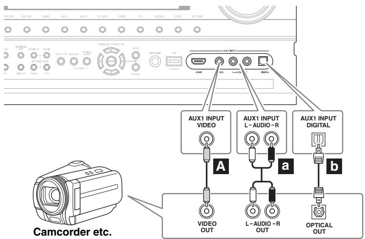
Connecting a CD Player or Turntable
CD Player or Turntable (MM) with Built-in Phono Preamp
Step 1:
Choose a connection that matches your CD player (a, b, or c). Use connection a for a turntable with a built-in phono preamp.
- With connection a, you can listen to and record audio from your CD player or listen in Zone 2 or Zone 3.
- To connect the CD player digitally, use connection b or c. (To record or listen in Zone 2 or Zone 3 as well, use a and b, or a and c.)
| Connection | AV controller | Signal flow | CD or turntable |
| a | CD IN L/R | ← | Analog audio L/R output |
| b | DIGITAL COAXIAL IN 2 (VCR/DVR) | ← | Digital coaxial output |
| c | DIGITAL OPTICAL IN 3 (CD) | ← | Digital optical output |
When you use connection b, you need to assign the digital audio input (see page 51).
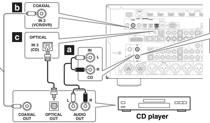
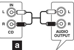
Turntable (MM) with built-in phono preamp
Turntable (MM) with no Phono Preamp Built-in
The AV controller's PHONO IN is designed for use with a moving magnet (MM) type cartridge.
Use an analog audio cable to connect the AV controller's PHONO IN L/R jacks to the audio output on your turntable.
Notes:
- If your turntable has a ground wire, connect it to the AV controller's GND screw. With some turntables, connecting the ground wire may produce an audible hum.
If this happens, disconnect it. - If your turntable has a moving coil (MC) type cartridge, you'll need a commercially available MC head amp or MC transformer. Connect your turntable to the head amp or transformer, and connect that to the AV controller's PHONO IN L/R jacks.
- You can also use a phono equalizer to connect a turntable with an MC-type cartridge. See your phono equalizer's manual for details.
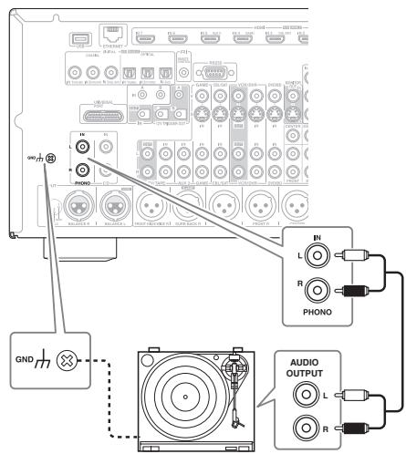
Turntable (MM) with no phono preamp built-in
Connecting a Cassette, CDR, MiniDisc, or DAT Recorder
Step 1:
Choose a connection that matches the recorder (a, b or c), and then make the connection.
- With connection a, you can play and record or listen in Zone 2 or Zone 3.
- To connect the recorder digitally for playback, use connections a and b, or a and c.
| Connection | AV controller | Signal flow | Cassette, CDR, MD, or DAT recorder |
| a | TV/TAPE IN L/R | ← | Analog audio L/R output |
| TV/TAPE OUT L/R | → | Analog audio L/R input | |
| b | DIGITAL COAXIAL IN 3 (CBL/SAT) | ← | Digital coaxial output |
| c | DIGITAL OPTICAL IN 2 (TV/TAPE) | ← | Digital optical output |
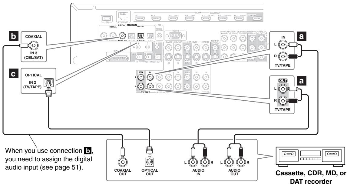
Connecting a Balanced Audio Source
You can connect a balanced audio source to the AV controller's BALANCE L/R XLR jacks by using two XLR audio cables. To use the balanced input, you must assign it to an input selector (see page 52). If you connect a mono source, use the BALANCE L XLR jack and set the "Input Channel" setting to "Mono(L)" (see page 52). The AV controller's balanced INPUT XLR jacks are wired as shown.
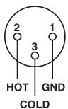
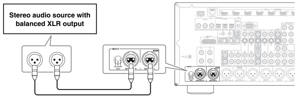
Connecting an RI Dock
Not all iPod models output video. For information about which iPod models are supported by the RI Dock, see the RI Dock's instruction manual.
If Your iPod Supports Video:
Connect your RI Dock's audio output jacks to the AV controller's GAME IN or VCR/DVR IN L/R jacks, and connect its video output jack to the AV controller's GAME IN V or VCR/DVR IN V jack. (Onkyo DS-A2 hookup shown below.)
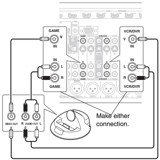
If you have an Onkyo DS-A1 RI Dock
Connect its video output jack to the AV controller's GAME IN S or VCR/DVR IN S jack.
If Your iPod Doesn't Support Video:
Connect your RI Dock's audio output jacks to the AV controller's TV/TAPE IN L/R jacks. (Onkyo DS-A2 hookup shown below.)
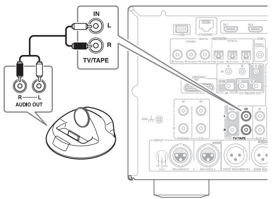
Notes:
- Enter the appropriate remote control code before using the AV controller's remote controller for the first time (see page 135).
- Connect the RI Dock to the AV controller with an RI cable (see page 42).
- Set the RI Dock's RI MODE switch to "HDD" or "HDD/DOCK".
- Set the AV controller's Input Display to "DOCK" (see page 55).
- See the RI Dock's instruction manual for more information.
Connecting a Universal Port Option Series
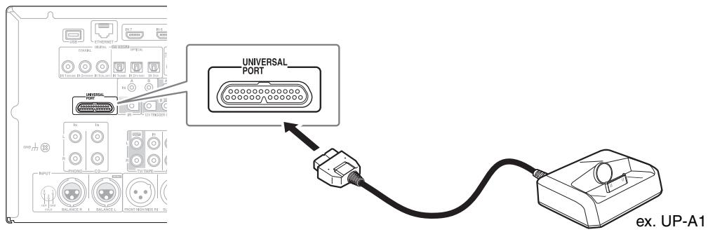
Note:
When UP-A1 Dock that seated iPod is connected, the power consumption on standby mode slightly increases.
Connecting Onkyo RI Components
Step 1:
Make sure that each Onkyo component is connected to the AV controller with an analog audio cable (connection in the hookup examples) (see pages 31 to 40, 41).
Step 2:
Make the RI connection (see illustration right).
Step 3:
If you're using an MD, CDR, or RI Dock, change the Input Display (see page 55).
With RI (Remote Interactive), you can use the following special functions:
Auto Power On/Standby
When you start playback on a component connected via RI, if the AV controller is on Standby, it will automatically turn on and select that component as the input source. Similarly, when the AV controller is set to Standby, all components connected via RI will also go on Standby.
Direct Change
When playback is started on a component connected via RI, the AV controller automatically selects that component as the input source.
Remote Control
You can use the AV controller's remote controller to control your other RI-capable Onkyo components, pointing the remote controller at the AV controller's remote control sensor instead of the component. You must enter the appropriate remote control code first (see page 136).
Notes:
- Use only RI cables for RI connections. RI cables are supplied with Onkyo players (DVD, CD, etc.).
- Some components have two RI jacks. You can connect either one to the AV controller. The other jack is for connecting additional RI-capable components.
- Connect only Onkyo components to RI jacks. Connecting other manufacturer's components may cause a malfunction.
- Some components may not support all R functions. Refer to the manuals supplied with your other Onkyo components.
- While Zone 2 or Zone 3 is on, the Auto Power On/Standby and Direct Change RI functions do not work.
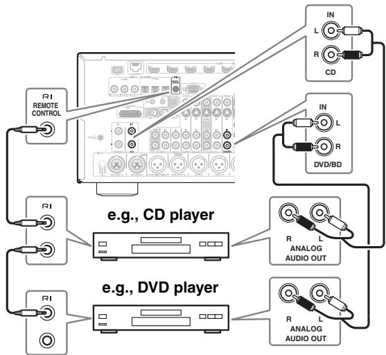
Connecting the Power Cord
Notes:
- Before connecting the power cord, connect all of your speakers and AV components.
- Turning on the AV controller may cause a momentary power surge that might interfere with other electrical equipment on the same circuit. If this is a problem, plug the AV controller into a different branch circuit.
- Do not use a power cord other than the one supplied with the AV controller. The supplied power cord is designed exclusively for use with the AV controller and should not be used with any other equipment.
- Never disconnect the power cord from the AV controller while the other end is still plugged into a wall outlet. Doing so may cause an electric shock. Always disconnect the power cord from the wall outlet first, and then the AV controller.
Step 1:
Connect the supplied power cord to the AV controller's AC INLET.
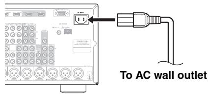
Step 2:
Plug the power cord into an AC wall outlet.
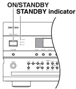
(North American models)
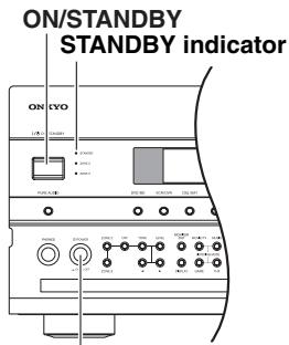
(European and Asian models)
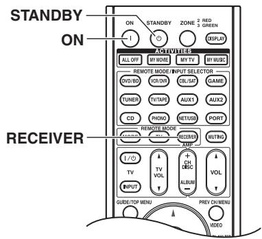
POWER
Turning On and Standby
1
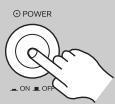
(European and Asian models)
Set the [POWER] switch to the ON position (■).
2
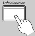
AV controller
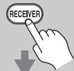
Remote controller
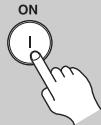
On the AV controller, press the [ON/STANDBY] button.
On the remote controller, press the [RECEIVER] button, followed by the [ON] button.
The AV controller comes on, the display lights up, and the STANDBY indicator goes off.
Pressing the remote controller's [ON] button again will turn on any components connected via R1.
To turn the AV controller off, press the [ON/STANDBY] button, or press the remote controller's [STANDBY] button. The AV controller will enter Standby mode. To prevent any loud surprises when you turn on the AV controller, always turn down the volume before you turn it off.
European and Asian models: To completely shut down the AV controller, set the [POWER] switch to the OFF position (■).
Smooth Operation in a Few Easy Steps
To ensure smooth operation, here's a few easy steps to help you configure the AV controller before you use it for the very first time. These settings only need to be made once.
■ Did you connect your TV to an HDMI output or COMPONENT VIDEO MONITOR OUT?
If you did, "Monitor Setup" on page 44.
■ Run MultEQ XT Room Correction and Speaker Setup—this is essential!
See "Audyssey MultEQ® XT Room Correction and Speaker Setup" on page 56.
Have you connected a component to an HDMI input, component video input, or digital audio input?
If you have, see "HDMI Input Setup" on page 49, "Component Video Input Setup" on page 50, or "Digital Audio Input Setup" on page 51 respectively.
Have you connected an Onkyo MD recorder, CD recorder, or RI Dock?
If you have, see "Changing the Input Display" on page 55.
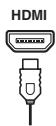
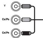


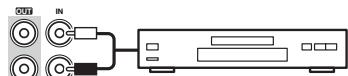
MD recorder, CD recorder, RI Dock
This section explains the settings that you need to make before using the AV controller for the very first time.
Monitor Setup
If you connect your TV to HDMI OUT MAIN, "Monitor Out" setting is automatically set so that the onscreen setup menus are displayed and composite video, S-Video, and component video sources are upconverted* and output.
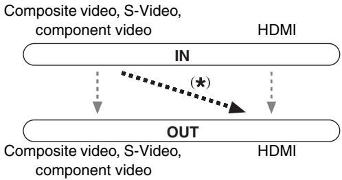
On the "Monitor Out" settings, you can select whether or not to have the video sources' images output through the HDMI output, as well as whether to have the onscreen setup menu output through the HDMI output or through an analog output.
If you connect your TV to the COMPONENT VIDEO MONITOR OUT (not the HDMI output), "Monitor Out" setting is automatically set so that the onscreen setup menus are displayed and composite video and S-Video sources are upconverted* and output.
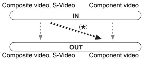
Change "Monitor Out" setting manually
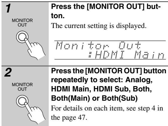
Tips:
- The "Monitor Out" setting can also be set using the [VIDEO] button on the remote controller.
- This setting can also be performed by using Onscreen Setup Menu (see page 47).
Notes:
- See page 28 for charts showing how the "Monitor Out" and "Resolution" (see page 47) settings affect the video signal flow through the AV controller.
- You can specify the output resolution for the HDMI outputs and COMPONENTVIDEOMONITOR OUT and have the AV controller upconvert the picture resolution as necessary to match the resolution supported by your TV (see page 47).
In this Instruction Manual, illustrations from the onscreen menu or explanations referring to the menu will be in the same language as the Instruction Manual. The default Language setting for the onscreen menu is English. If your Instruction Manual is in a language other than English, first follow the instructions below to change the Language.
Selecting the Language used for the onscreen setup menus
This setting determines the language used for the onscreen setup menus. You can select: English, German, French, Spanish, Italian, Dutch, Swedish, or Chinese.
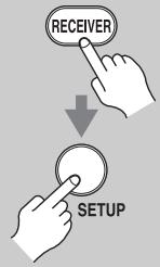
1
Press the [RECEIVER] button, followed by the [SETUP] button.
The main menu appears onscreen. If the main menu doesn't appear, make sure the appropriate external input is selected on your TV.
Menu
- Input/Output Assign
- Speaker Setup
- Audio Adjust
- Source Setup
- Listening Mode Preset
- Miscellaneous
- Hardware Setup
- Remote Controller Setup
- Lock Setup
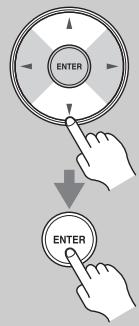
2
Use the Up and Down [A]/[V] buttons to select "6. Miscellaneous", and then press [ENTER].
The "Miscellaneous" menu appears.
6. Miscellaneous
- Volume Setup
- QSD Setup
- 12V Trigger A Setup
- 12V Trigger B Setup
- 12V Trigger C Setup
Use the Up and Down [A]/[V] buttons to select "2. OSD Setup", and then press [ENTER].
The "OSD Setup" menu appears.
![ONKYO PR-SC5507 - Use the Up and Down [A]/[V] buttons to select "2. OSD Setup", and then press [ENTER]. - 1](/content/2025/01/151815/images/88e40f7959e5e338ec8dac1580e89810ab1695fcb20fc31bba332af9293c602e.jpg)
(European and Asian models)
![ONKYO PR-SC5507 - Use the Up and Down [A]/[V] buttons to select "2. OSD Setup", and then press [ENTER]. - 2](/content/2025/01/151815/images/a93ddb8baeec5320e0df05a2c8e0b0ce9a71a3cadef60c2b09b139cbab07c291.jpg)
4
Use the Up and Down [▲]/[▼] buttons to select "Language", and then use the Left and Right [▲]/[▶] buttons to select:
English, Deutsch, Français, Espanol, Italiano, Nederlands, Svenska,中文
![ONKYO PR-SC5507 - Use the Up and Down [▲]/[▼] buttons to select "Language", and then use the Left and Right [▲]/[▶] buttons to select: - 1](/content/2025/01/151815/images/d0ad370102ee3cfa14a7bffe5deb7cfa42f9887abb0119b6776cc5f1ca1a236f.jpg)
5
Press the [SETUP] button.
The setup menu closes.
Note:
This procedure can also be performed on the AV controller by using its [SETUP] button, arrow buttons, and [ENTER] button.
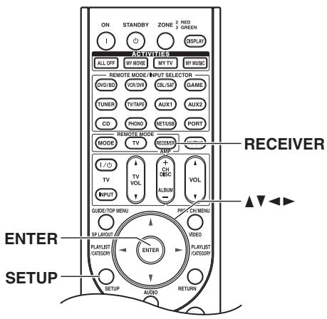
Using the Onscreen Setup Menus
Carry out the settings for the AV controller by using the Onscreen Setup Menu.
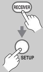
1
Press the [RECEIVER] button followed by the [SETUP] button.
The main menu appears onscreen. If the main menu doesn't appear, make sure the appropriate external input is selected on your TV.
Menu
1. Input/Output Assign
2. Speaker Setup
3. Audio Adjust
4. Source Setup
5. Listening Mode Preset
6. Miscellaneous
7. Hardware Setup
8. Remote Controller Setup
9. Lock Setup
Tip:
On several functions, the explanation will be displayed under the screen.

2
Use the Up and Down [A]/[V] buttons to select item and then press [ENTER].
The submenu appears.
Press the [SETUP] button to close the menu.
Press the [RETURN] button to return to the previous menu.
Using the Display to change the settings
The settings of the AV controller can be changed using the Display.
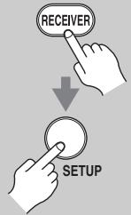
1
Press the [RECEIVER] button followed by the [SETUP] button.
The main menu item appears on the display.
- Input/Output
Hessian
![ONKYO PR-SC5507 - Press the [RECEIVER] button followed by the [SETUP] button. - 1](/content/2025/01/151815/images/47bf513218f6180aeaf1895398bd586c69fc6688cdf18b186a85e0c66c58207a.jpg)
2
Use the Up and Down [A]/[V] buttons to select item and then press [ENTER].
The submenu item appears on the display.
Press the [SETUP] button to close the menu.
Press the [RETURN] button to return to the previous menu.
Onscreen Setup Menus and Display
As each item in the Onscreen Setup Menus is selected, the selected items will be displayed one by one.
Onscreen Setup Menus
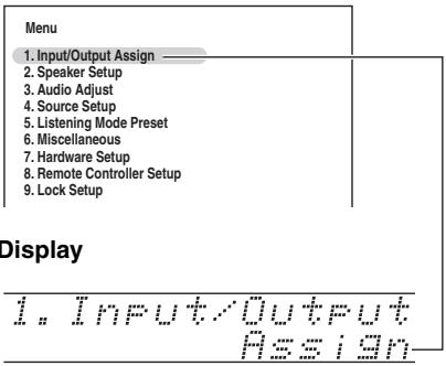
Note:
During Audyssey MultEQ® XT Room Correction and Speaker Setup, messages, etc., that are displayed on the TV screen will appear in the Display.
Monitor Out Setup
If you connect your TV to the HDMI output, set the "Monitor Out" setting so that the onscreen setup menus are displayed and composite video, S-Video, and component video sources are upconverted and output. If you connect your TV to the COMPONENT VIDEO MONITOR OUT, set the "Monitor Out" setting so that the onscreen setup menus are displayed and composite video and S-Video sources are upconverted and output. You can specify the output resolution for the HDMI outputs and COMPONENT Video MONITOR OUT and have the AV controller upconvert the picture resolution as necessary to match the resolution supported by your TV.

1
Press the [RECEIVER] button, followed by the [SETUP] button.
The main menu appears onscreen. If the main menu doesn't appear, make sure the appropriate external input is selected on your TV.
![ONKYO PR-SC5507 - Press the [RECEIVER] button, followed by the [SETUP] button. - 1](/content/2025/01/151815/images/a89e3abd8044aff5be57c037cb1c0718fa6011d37ecbdbae878d950673cd0e5a.jpg)
2
Use the Up and Down [A]/[V] buttons to select "1. Input/Output Assign", and then press [ENTER].
The "Input/Output Assign" menu appears.
1. Input/Output Assign
- Monitor Out
- HDMI Input
- Component Video Input
4 Digital Audio Input - Analog Audio Input
- Gamma Curve

3
Use the Up and Down [A]/[V] buttons to select "1. Monitor Out", and then press [ENTER].
The "Monitor Out" menu appears.
![ONKYO PR-SC5507 - Use the Up and Down [A]/[V] buttons to select "1. Monitor Out", and then press [ENTER]. - 1](/content/2025/01/151815/images/238205065238c59f08bb024f1411fa98a9d19f65acd450d53b5a9292ea37dfb7.jpg)
![ONKYO PR-SC5507 - Use the Up and Down [A]/[V] buttons to select "1. Monitor Out", and then press [ENTER]. - 2](/content/2025/01/151815/images/a3cc38ed72cf86a3d4bff0ee27aa306554e0200931ddbe21df5876132b4d0fd0.jpg)
4
Use the Up and Down [▲]/[▼] buttons to select "Monitor Out", and use the Left and Right [▲]/[▶] buttons to select:
Analog:
Select this if your TV is connected to the COMPONENTVIDEO MONITOR OUT, S MONITOR OUT, or V MONITOR OUT.
HDMI Main:
Select this if your TV is connected to the HDMI OUT MAIN.
HDMI Sub:
Select this if your TV is connected to the HDMI OUT SUB.
Both:
Select this if your TVs are connected to the HDMI OUT MAIN and HDMI OUT SUB. Video signals are output from both HDMI outputs at the resolution supported by both TVs.
Both (Main):
Select this if your TVs are connected to the HDMI OUT MAIN and HDMI OUT SUB. Video signals are output from both HDMI outputs but HDMI OUT MAIN will become a priority; depending on the resolution, video signals may not be output from HDMI OUT SUB.
Both (Sub):
Select this if your TVs are connected to the HDMI OUT MAIN and HDMI OUT SUB. Video signals are output from both HDMI outputs but HDMI OUT SUB will become a priority; depending on the resolution, video signals may not be output from HDMI OUT MAIN.
Notes:
- If not connected to the same output you have selected in the "Monitor Out" setting, the "Monitor Out" setting will be automatically switched to "Analog".
- When you select other than "Analog", the onscreen setup menus are output by only the HDMI outputs. If you're not using the HDMI output and select settings by mistake and the menus disappear, press the [MONITOR OUT] button to select "Analog".
- For Deep Color output, if the "Monitor Out" setting is set to "Both (Main)" or "Both (Sub)", the number of bit may be limited due to the capability of your TV connected to a priority output.
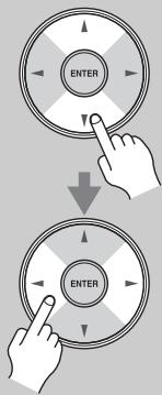
5
Use the Up and Down [A]/[▼] buttons to select "Resolution", and use the Left and Right [▲]/[▶] buttons to select:
Through:
Select this to pass video through the AV controller at the same resolution and with no conversion.
Auto*:
Select this to have the AV controller automatically convert video at resolutions not supported by your TV.
480p (480p/576p):
Select this for 480p or 576p output and video conversion as necessary.
720p:
Select this for 720p output and video conversion as necessary.
1080i:
Select this for 1080i output and video conversion as necessary.
1080p*:
Select this for 1080p output and video conversion as necessary.
1080p/24*:
Select this for 1080p output at 24 frames per second and video conversion as necessary.
Source:
Output will be according to the resolution level which was set in the "Picture Adjust" setting (see page 99).
Tips:
- The "Resolution" setting can also be set using the [VIDEO] button on the remote controller.
- The "Resolution" setting is set respectively of main, sub, and analog.
Notes:
- Settings marked with an asterisk (*) are not available when the "Monitor Out" setting is set to "Analog".
- If the "Monitor Out" setting is set to "Both", this setting is fixed at "Auto".
Depending on the incoming video signal, video playback may not be smooth or the vertical resolution may be lowered. In this case select other than "1080p/24".
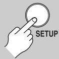
6
Press the [SETUP] button.
The setup menu closes.
Notes:
- See page 28 for charts showing how the "Monitor Out" and "Resolution" settings affect the video signal flow through the AV controller.
- This procedure can also be performed on the AV controller by using its [SETUP] button, arrow buttons, and [ENTER] button.
Video Input Setup
HDMI Input Setup
If you connect a video component to HDMI IN, you must assign that input to an input selector. For example, if you connect your DVD/BD player to HDMI IN 1, you must assign HDMI IN 1 to the DVD/BD input selector. If you've connected your TV to the AV controller with an HDMI cable, you can set the AV controller so that composite video, S-Video, and component video sources are upconverted* and output by the HDMI output. You can set this for each input selector by selecting the "- - - - - " option.
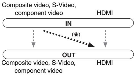
Press the [RECEIVER] button followed by the [SETUP] button.
The main menu appears onscreen. If the main menu doesn't appear, make sure the appropriate external input is selected on your TV.
![ONKYO PR-SC5507 - Press the [RECEIVER] button followed by the [SETUP] button. - 1](/content/2025/01/151815/images/be11e2502f27ea54fd0471a94c487803d6423544c28020d187201d07b1cb1477.jpg)
Use the Up and Down [A]/[V] buttons to select "1. Input/Output Assign", and then press [ENTER].
The "Input/Output Assign" menu appears.
![ONKYO PR-SC5507 - Use the Up and Down [A]/[V] buttons to select "1. Input/Output Assign", and then press [ENTER]. - 1](/content/2025/01/151815/images/13b2045abca62c51784815f0a63b479f53fca8fbb6094cce316d710011ee1d8a.jpg)
![ONKYO PR-SC5507 - Use the Up and Down [A]/[V] buttons to select "1. Input/Output Assign", and then press [ENTER]. - 2](/content/2025/01/151815/images/7253b5577df57c28e49ea68ec2ae103fbd8871bd172be5afdf94ddc0921ffbe9.jpg)
Use the Up and Down [A]/[V] buttons to select "2. HDMI Input", and then press [ENTER].
The "HDMI Input" menu appears.
![ONKYO PR-SC5507 - Use the Up and Down [A]/[V] buttons to select "2. HDMI Input", and then press [ENTER]. - 1](/content/2025/01/151815/images/fe93c68179152a2913995e31b5176f8e86baa9faebe8535dbbb99f47b7dbe419.jpg)
![ONKYO PR-SC5507 - Use the Up and Down [A]/[V] buttons to select "2. HDMI Input", and then press [ENTER]. - 2](/content/2025/01/151815/images/19b50ffff83bf53973ab871d336448cf37ed68598f3827eb31954ea9ed825cb7.jpg)
4
Use the Up and Down [▲]/[▼] buttons to select an input selector, and use the Left and Right [▲]/[▶] buttons to select:
HDMI1, HDMI2, HDMI3, HDMI4, HDMI5, HDMI6, HDMI7:
Select the HDMI IN to which the video component has been connected.
-
-
-
- : Output composite video, S-Video, and component video sources from the HDMI outputs. The video output signal from the HDMI outputs is the one configured in "Component Video Input Setup" (see page 50).
-
-
Each HDMI IN cannot be assigned to more than one input selector. When HDMI IN have already been assigned, you must set first any unused input selectors to "---" or you will be unable to assign HDMI IN to input selector.
"AUX 1" is used only for digital input from the front panel terminals.
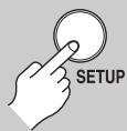
5
Press the [SETUP] button.
The setup menu closes.
Notes:
- For composite video, S-Video, and component video upconversion for the HDMI output, the "Monitor Out" setting must be set to other than "Analog" (see page 47), and the "HDMI Input" setting must be set to "- - - -". See page 28 for more information on video signal flow and upconversion.
- If no video component is connected to HDMI output (even if the HDMI input is assigned), the AV controller selects the video source based on the setting of Component Video Input.
- When an HDMI IN is assigned to an input selector, the AV controller will select audio from HDMI IN as a priority. See "Digital Audio Input Setup" on page 51.
- The TUNER input selector cannot be assigned and is fixed at the “-- --” option.
- If you connect an input component (such as UP-A1 Dock that seated iPod) to the UNIVERSAL PORT jack, you cannot assign any input to PORT selector.
- Do not assign the component connected with the HDMI input to the TV/TAPE selector when you set "TV Control" setting to "On" (see page 109). Otherwise, appropriate CEC (Consumer Electronics Control) operation is not guaranteed.
- This procedure can also be performed on the AV controller by using its [SETUP] button, arrow buttons, and [ENTER] button.
Component Video Input Setup
If you connect to a COMPONENT Video IN or PC INPUT ANALOG RGB, you must assign it to an input selector. For example, if you connect your DVD/BD player to COMPONENT Video IN 2, you should assign it to the DVD/BD input selector.
If you've connected your TV to the AV controller with a component video cable, you can set the AV controller so that composite video and S-Video sources are upconverted and output by the COMPONENT VIDEO MONITOR OUT ^1 . You can set this for each input selector by selecting the "---" option.

*1 Only when "Monitor Out" setting is set to "Analog".
Press the [RECEIVER] button followed by the [SETUP] button.
The main menu appears onscreen. If the main menu doesn't appear, make sure the appropriate external input is selected on your TV.
![ONKYO PR-SC5507 - Press the [RECEIVER] button followed by the [SETUP] button. - 1](/content/2025/01/151815/images/89df966db20815423d1fb5ddd1af55768db38faa870e5ae517661aa63b33cab5.jpg)
2
Use the Up and Down [A]/[V] buttons to select "1. Input/Output Assign", and then press [ENTER].
The "Input/Output Assign" menu appears.
![ONKYO PR-SC5507 - Use the Up and Down [A]/[V] buttons to select "1. Input/Output Assign", and then press [ENTER]. - 1](/content/2025/01/151815/images/27d145515e576544c51517b82a62b049eaa42e7d6240c360e6b2460e7f2d3aa0.jpg)
![ONKYO PR-SC5507 - Use the Up and Down [A]/[V] buttons to select "1. Input/Output Assign", and then press [ENTER]. - 2](/content/2025/01/151815/images/024d4d1dec551e2533d15e339d7d42558fab5e767a59697aca9c6bf630c304b9.jpg)
3
Use the Up and Down [A]/[V] buttons to select "3. Component Video Input", and then press [ENTER].
The "Component Video Input" menu appears.
![ONKYO PR-SC5507 - Use the Up and Down [A]/[V] buttons to select "3. Component Video Input", and then press [ENTER]. - 1](/content/2025/01/151815/images/78495ad92372dd1be174e1e6f3ac7e072bdf53f3f316a2d40e999682e8126a73.jpg)
![ONKYO PR-SC5507 - Use the Up and Down [A]/[V] buttons to select "3. Component Video Input", and then press [ENTER]. - 2](/content/2025/01/151815/images/f336817af9e697feaf3788c2a347f31e9670d99ef5724d029d43165e5dac9e91.jpg)
4
Use the Up and Down [▲]/[▼] buttons to select an input selector, and then use the Left and Right [▲]/[▶] buttons to select:
IN1: Select if the video component is connected to COMPO-NENTVIDEO IN 1.
IN2: Select if the video component is connected to COMPO-NENTVIDEO IN 2.
IN3: Select if the video component is connected to COMPO- NENTVIDEO IN 3.
PCIN: Select if the personal computer is connected to PC INPUT ANALOG RGB.
- Select if you are using the HDMI outputs, rather than the COMPONENT VIDEO OUT, for the output from composite video, S-Video, and component video sources.
![ONKYO PR-SC5507 - Use the Up and Down [▲]/[▼] buttons to select an input selector, and then use the Left and Right [▲]/[▶] buttons to select: - 1](/content/2025/01/151815/images/11802466ea9b38906813e53341978fbe9c4803cea1b50a338bc2746b2414e166.jpg)
5
Press the [SETUP] button.
The setup menu closes.
Notes:
- For composite video and S-Video upconversion for the COMPONENT VIDEO MONITOR OUT, the "Monitor Out" setting must be set to "Analog" (see page 47), and the "Component Video Input" setting must be set to "----". See page 28 for more information on video signal flow and upconversion.
- If not connected to the same output you have selected in the "Monitor Out" setting, the "Monitor Out" setting will be automatically switched to "Analog" (see page 47).
- If you connect an input component (such as UP-A1 Dock that seated iPod) to the UNIVERSAL PORT jack, you cannot assign any input to PORT selector.
- This procedure can also be performed on the AV controller by using its [SETUP] button, arrow buttons, and [ENTER] button.
About PC Input
Signals from PC INPUT ANALOG RGB are output from the HDMI output without the resolution conversion.
Supported Resolution:
VGA (640× 480) 60 / 72 / 75 / 85Hz
- SVGA (800 × 600) 56/60/72/75/85 Hz
XGA (1024× 768) 60 / 70 / 75 / 85Hz
- SXGA (1280 × 1024) 60 / 75Hz
Note:
The picture adjust setting is effective for only 60Hz
Digital Audio Input Setup
If you connect a component to a digital input jack, you must assign that jack to an input selector. For example, if you connect your CD player to the OPTICAL IN1 jack, you should assign that jack to the CD input selector. By default, the COAXIAL IN1 jack is assigned to the DVD/ BD input selector, although this can be changed. Here are the default assignments.
| Input selector | Default assignment |
| DVD/BD | COAX1 |
| VCR/DVR | COAX2 |
| CBL/SAT | COAX3 |
| GAME | OPT1 |
| AUX 1 | FRONT (Fixed) |
| AUX 2 | -------- |
| TV/TAPE | OPT2 |
| TUNER | -------- (Fixed) |
| CD | OPT3 |
| PHONO | -------- |
| PORT | -------- |
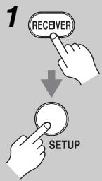
Press the [RECEIVER] button followed by the [SETUP] button.
The main menu appears onscreen. If the main menu doesn't appear, make sure the appropriate external input is selected on your TV.
![ONKYO PR-SC5507 - Press the [RECEIVER] button followed by the [SETUP] button. - 1](/content/2025/01/151815/images/3375fb5f66bc6fd1fe6589e6ce82d095ef7708e0ce6d6e5a3ba89a433e11510a.jpg)
Use the Up and Down [A]/[V] buttons to select "1. Input/Output Assign", and then press [ENTER].
The "Input/Output Assign" menu appears.
![ONKYO PR-SC5507 - Use the Up and Down [A]/[V] buttons to select "1. Input/Output Assign", and then press [ENTER]. - 1](/content/2025/01/151815/images/2fbd94cfa6ec60397e141291898abcfe773120e99beeace0f6a41ba658576f6d.jpg)
![ONKYO PR-SC5507 - Use the Up and Down [A]/[V] buttons to select "1. Input/Output Assign", and then press [ENTER]. - 2](/content/2025/01/151815/images/3835db03af88b446223d6c6a14a09cc41905d0ce8d0a4804add64705986d5295.jpg)
Use the Up and Down [A]/[V] buttons to select "4. Digital Audio Input", and then press [ENTER].
The "Digital Audio Input" menu appears.
![ONKYO PR-SC5507 - Use the Up and Down [A]/[V] buttons to select "4. Digital Audio Input", and then press [ENTER]. - 1](/content/2025/01/151815/images/a6fb95431a9553798247ee5a1b7c0bb04dad10eb2ab2ec7836f6da1d629e5264.jpg)
![ONKYO PR-SC5507 - Use the Up and Down [A]/[V] buttons to select "4. Digital Audio Input", and then press [ENTER]. - 2](/content/2025/01/151815/images/79835c47b952d62248e8c512992299d9849bc7651dc183d66f497832981bbbd9.jpg)
4
Use the Up and Down [A]/[V] buttons to select an input selector, and use the Left and Right [<] /[>] buttons to select "COAX1", "COAX2", "COAX3", "OPT1", "OPT2", "OPT3", or "-----(analog)".
- When an HDMI IN is assigned to an input selector in "HDMI Input Setup" on page 49, the AV controller will select audio from HDMI IN as a priority.
- Press the [ENTER] button when you do not use the signal of audio from the HDMI IN. The “” mark is displayed like “COAX1”.
"AUX 1" is used only for digital input from the front panel terminals.
Examples:
If you connect your DVD player to the OPTICAL IN 1 jack, set "DVD/BD" to "OPT1".
If you want to listen to audio from the component connected to the OPTICAL IN 2 jack when the VCR/DVR input selector is selected, set "VCR/DVR" to "OPT2".
If you want to listen to audio from the component connected to the COAXIAL IN 1 jack when the CBL/ SAT input selector is selected, set "CBL/SAT" to "COAX1".
For input selectors that you don't want to assign a digital input jack, set to "---(analog)".
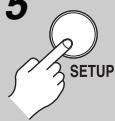
5
Press the [SETUP] button.
The setup menu closes.
Notes:
- Available sampling rate for PCM signals from a digital input (optical and coaxial) is 32/44.1/48/88.2/96 kHz/16, 20, 24 bit.
- If you connect an input component (such as UP-A1 Dock that seated iPod) to the UNIVERSAL PORT jack, you cannot assign any input to PORT selector.
- This procedure can also be performed on the AV controller by using its [SETUP] button, arrow buttons, and [ENTER] button.
Analog Audio Input Setup
If you connect a component to the AV controller's analog multichannel input, you must assign that input to an input selector. For example, if you connect your DVD/ BD player to the multichannel input, you must assign it to the DVD/BD input selector.
If you connect a component to the AV controller's balanced input, you must assign that input to an input selector. For example, if you connect your CD player to the balanced input, you must assign it to the CD input selector.
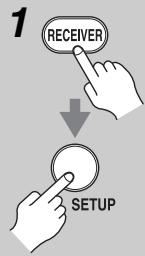
Press the [RECEIVER] button, followed by the [SETUP] button.
The main menu appears onscreen. If the main menu doesn't appear, make sure the appropriate external input is selected on your TV.
![ONKYO PR-SC5507 - Press the [RECEIVER] button, followed by the [SETUP] button. - 1](/content/2025/01/151815/images/c8f475120ecf771aede98d730a82a313131d3cf41db5bf7765a339630dede1ef.jpg)
2
Use the Up and Down [A]/[V] buttons to select "1. Input/Output Assign", and then press [ENTER].
The "Input/Output Assign" menu appears.
1. Input/Output Assign
- Monitor Out
- HDMI Input
- Component Video Input
- Digital Audio Input
- Analog Audio Input
- Gamma Curve

3
Use the Up and Down [A]/[V] buttons to select "5. Analog Audio Input", and then press [ENTER].
The "Analog Audio Input" menu appears.
![ONKYO PR-SC5507 - Use the Up and Down [A]/[V] buttons to select "5. Analog Audio Input", and then press [ENTER]. - 1](/content/2025/01/151815/images/4341807c33312afa9dfdf27e093d3a25c7d47dc0952fe78a0d9222c4443f4e1b.jpg)
![ONKYO PR-SC5507 - Use the Up and Down [A]/[V] buttons to select "5. Analog Audio Input", and then press [ENTER]. - 2](/content/2025/01/151815/images/007ee95d2b60bb76ee5c400a32fe7b41a2cb16f821f7c9ce8df5a5be6f3a9e62.jpg)
4
Use the Left and Right []/[] buttons to select an input selector.
You can assign the multichannel input to the following input selectors: "DVD/ BD", "VCR/DVR", "CBL/SAT", "GAME", "AUX1", "AUX2", "TV/ TAPE", "CD", or "PHONO". If you don't want to assign the multichannel input, set to ^- - - - -
![ONKYO PR-SC5507 - Use the Left and Right []/[] buttons to select an input selector. - 1](/content/2025/01/151815/images/434c2e7169897a66d433e40a769a26a63e7fdc332cb1a821b531546cb24566ef.jpg)
5
Use the Up and Down [▲]/[▼] buttons to select "Balance", and use the Left and Right [▲]/[▶] buttons to select an input selector:
You can assign the balanced input to the following input selectors: "DVD/ BD", "VCR/DVR", "CBL/SAT", "GAME", "AUX1", "AUX2", "TV/ TAPE", "CD", or "PHONO". If you don't want to assign the balanced input, set to "- - - - -".
![ONKYO PR-SC5507 - Use the Up and Down [▲]/[▼] buttons to select "Balance", and use the Left and Right [▲]/[▶] buttons to select an input selector: - 1](/content/2025/01/151815/images/132034b318034d5c3ecbd7ee9c0174076eb40fe82e4f62e707fd37b51182b2b0.jpg)
6
Use the Up and Down [ ] / [ ] buttons to select "Input Channel", and use the Left and Right [ ]/ [▶] buttons to select:
Stereo:
Select if the source is stereo and you've connected it to the INPUT:BALANCE L/R jacks.
Mono(L):
Select if the source is mono and you've connected it to the INPUT:BALANCE L jack.
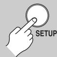
7
Press the [SETUP] button.
The setup menu closes.
Notes:
- To listen to the component connected to the multi-channel input or balanced input, press the [AUDIO] button and select the "Audio selector" (see page 114).
- This procedure can also be performed on the AV controller by using its [SETUP] button, arrow buttons, and [ENTER] button.
Speaker Settings
If you change these settings, you must run Audyssey MultEQXT Room Correction and Speaker Setup again (see page 56).
If you've fed your front speakers from the FRONT L/R and SURR BACK L/R outputs for bi-amping, you must change the "Speakers Type(Front)" setting. For hookup information, see "Bi-amping the Front Speakers" on page 21.
Notes:
- When bi-amping is used, the AV controller is able to feed up to 7.2 speakers in the main room.
- Before you change these settings, turn down the volume.
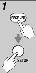
Press the [RECEIVER] button, followed by the [SETUP] button.
The main menu appears onscreen. If the main menu doesn't appear, make sure the appropriate external input is selected on your TV.
![ONKYO PR-SC5507 - Press the [RECEIVER] button, followed by the [SETUP] button. - 1](/content/2025/01/151815/images/87178be8d9150de4e770dfe5c2aa4fc9273740f66fa07121a0719b65472086f6.jpg)
Use the Up and Down [A]/[V] buttons to select "2. Speaker Setup", and then press [ENTER].
The "Speaker Setup" menu appears.
2. Speaker Setup
- Speaker Settings
- Speaker Configuration
- Speaker Distance
- Level Calibration
- Equalizer Settings
- THX Audio Setup
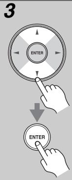
Use the Up and Down [A]/[V] buttons to select "1. Speaker Settings", and then press [ENTER].
The "Speaker Settings" menu appears.
2-1. Speaker Settings
Speakers Type(Front)
Normal
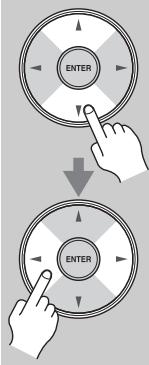
4
Use the Up and Down [A]/[V] buttons to select "Speakers
Type(Front)”, and then use the Left and Right [] / [] buttons to select:
Normal: Select this if you've connected your front speakers normally.
Bi-Amp: Select this if you've connected your front speakers for bi-amped operation.
Note:
Surround back speakers cannot be used if you select "Bi-Amp".

5
Press the [SETUP] button.
The setup menu closes.
Note:
This procedure can also be performed on the AV controller by using its [SETUP] button, arrow buttons, and [ENTER] button.
TV Format Setup (European and Asian models)
For the onscreen setup menus to display properly, you must specify the TV system used in your area.
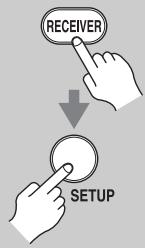
1
Press the [RECEIVER] button followed by the [SETUP] button.
The main menu appears onscreen. If the main menu doesn't appear, make sure the appropriate external input is selected on your TV.
![ONKYO PR-SC5507 - Press the [RECEIVER] button followed by the [SETUP] button. - 1](/content/2025/01/151815/images/de0e87d2e2d85bc44ed0ffa7474be17d60d7809bf97ee3635314e117a951f725.jpg)
2
Use the Up and Down [A]/[V] buttons to select "6. Miscellaneous", and then press [ENTER].
The "Miscellaneous" menu appears.
![ONKYO PR-SC5507 - Use the Up and Down [A]/[V] buttons to select "6. Miscellaneous", and then press [ENTER]. - 1](/content/2025/01/151815/images/59898933a1a2d7ff617d649e7c1304fb5cd5b9f652212cc6b6d1a5fb42602eef.jpg)
6. Miscellaneous
![ONKYO PR-SC5507 - Use the Up and Down [A]/[V] buttons to select "6. Miscellaneous", and then press [ENTER]. - 2](/content/2025/01/151815/images/c4cb37010520e21f4c58fa6f02c2c1899926d2479f6a120efdbf2867952f469c.jpg)
3
Use the Up and Down [A]/[V] buttons to select "2. OSD Setup", and then press [ENTER].
The "OSD Setup" menu appears.
![ONKYO PR-SC5507 - Use the Up and Down [A]/[V] buttons to select "2. OSD Setup", and then press [ENTER]. - 1](/content/2025/01/151815/images/17e302d47b83561b0ad8cf32826b29348ebca29f80704f23106f0fdc2fa63c08.jpg)
6-2. OSD Setup
![ONKYO PR-SC5507 - Use the Up and Down [A]/[V] buttons to select "2. OSD Setup", and then press [ENTER]. - 2](/content/2025/01/151815/images/487019a4b8a32ff21733c2bae62712860181548c8b8f26c6283d553c559b99d7.jpg)
4
Use the Up and Down [A]/[V] buttons to select "TV Format", and then use the Left and Right
[] / [] buttons to select:
Auto: Select this to automatically detect the TV system from the video input signals.
NTSC: Select if the TV system in your area is NTSC.
PAL: Select if the TV system in your area is PAL.
![ONKYO PR-SC5507 - [] / [] buttons to select: - 1](/content/2025/01/151815/images/e4ea69b51014db243efc72eb078d62b1d51ce3c5c73db2ee36065c569157a9fb.jpg)
5
When you've finished, press the [SETUP] button.
The setup menu closes.
Note:
This procedure can also be performed on the AV controller by using its [SETUP] button, arrow buttons, and [ENTER] button.
FM/AM Frequency Step Setup
For FM/AM tuning to work properly, you must specify the FM/AM frequency step used in your area. Note that when this setting is changed, all radio presets are deleted.
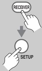
1
Press the [RECEIVER] button, followed by the [SETUP] button.
The main menu appears onscreen. If the main menu doesn't appear, make sure the appropriate external input is selected on your TV.
![ONKYO PR-SC5507 - Press the [RECEIVER] button, followed by the [SETUP] button. - 1](/content/2025/01/151815/images/5df5d83dc84d16448db828ba8cecdf71a665f13be207ff8dd8da3e6ba14edd77.jpg)
2
Use the Up and Down [A]/[▼] buttons to select "7. Hardware Setup", and then press [ENTER].
The "Hardware Setup" menu appears.
![ONKYO PR-SC5507 - Use the Up and Down [A]/[▼] buttons to select "7. Hardware Setup", and then press [ENTER]. - 1](/content/2025/01/151815/images/a0e8612a39603996e4ff590d88c1b041ce108effe8bf15dbe75d7bcab7867ba3.jpg)
7. Hardware Setup
![ONKYO PR-SC5507 - Use the Up and Down [A]/[▼] buttons to select "7. Hardware Setup", and then press [ENTER]. - 2](/content/2025/01/151815/images/41c39e4aa1795f94a56ca42d46e4b43fdd46374adfc132df71a8428a06cec02a.jpg)
3
Use the Up and Down [] / [] buttons to select "3. Tuner", and then press [ENTER].
The "Tuner" menu appears.
(North American models)
![ONKYO PR-SC5507 - Use the Up and Down [A]/[▼] buttons to select "7. Hardware Setup", and then press [ENTER]. - 3](/content/2025/01/151815/images/6be66721c7765f4e167eb8aff262e745fa6c491d7ca0a9a934250bb96e58f420.jpg)
(European and Asian models)
![ONKYO PR-SC5507 - Use the Up and Down [A]/[▼] buttons to select "7. Hardware Setup", and then press [ENTER]. - 4](/content/2025/01/151815/images/abff9bbc3d9c5aa8eec80cee6b9db6f891a28d5332cb2589fc18ab9569d74dd3.jpg)
![ONKYO PR-SC5507 - Use the Up and Down [A]/[▼] buttons to select "7. Hardware Setup", and then press [ENTER]. - 5](/content/2025/01/151815/images/f79818f258f05567e21542bdb81ed95e4e5bdbadd9a18abca8efced9e28a484d.jpg)
4
Use the Left and Right [] / [] buttons to select:
(North American models)
200kHz/10kHz:
Select if 200kHz / 10kHz steps are used in your area.
50kHz/9kHz:
Select if 50kHz / 9kHz steps are used in your area.
(European and Asian models)
10kHz: Select if 10kHz steps are used in your area.
9kHz: Select if 9 kHz steps are used in your area.
![ONKYO PR-SC5507 - Use the Up and Down [A]/[▼] buttons to select "7. Hardware Setup", and then press [ENTER]. - 6](/content/2025/01/151815/images/4d5c2748b75312aa64e41a2d8ada18c9c7d4e1f991ee08a89325ae8dd7dc487e.jpg)
5
Press the [SETUP] button.
The setup menu closes.
Note:
This procedure can also be performed on the AV controller by using its [SETUP] button, arrow buttons, and [ENTER] button.
Changing the Input Display
If you connect an RI-capable Onkyo MiniDisc
recorder, CD recorder, or RI Dock to the TV/TAPE IN/OUT jacks, or connect an RI Dock to the GAME IN or VCR/DVR IN jacks, for to work properly, you must change this setting.
This setting can only be changed on the AV controller.
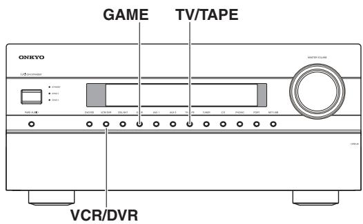

1
TV/TAPE
or

GAME
or

VCR/DVR
Press the [TV/TAPE], [GAME] or [VCR/DVR] input selector button so that "TV/TAPE", "GAME" or "VCR/DVR" appears on the display.
TUTape
1 1 1 1 1 1 1 1 1 1 1 1 1 1 1 1
UCF.DUR

2
TV/TAPE
or

GAME
or

VCR/DVR
(3 seconds)
Press and hold down the [TV/ TAPE], [GAME] or [VCR/DVR] input selector button (about 3 seconds) to change the setting.
Repeat this step to select MD, CDR, or DOCK.
For the TV/TAPE input selector, the setting changes in this order:
TV/TAPE MD CDR
—DOCK
For the GAME input selector, the setting changes in this order:
GAME DOCK
For the VCR/DVR input selector, the setting changes in this order:
VCR/DVR DOCK
Notes:
- DOCK can be selected for the TV/TAPE or GAME or VCR/DVR input selector, but not at the same time.
- Enter the appropriate remote control code before using the AV controller's remote controller for the first time (see page 135).
Audyssey MultEQ® XT Room Correction and Speaker Setup
With the supplied calibrated microphone,
Audyssey MultEQ XT automatically determines the number of speakers connected, their size for purposes of bass management, optimum crossover frequencies to the subwoofer (if present), and distances from the primary listening position.
Audyssey MultEQ XT then removes the distortion caused by room acoustics by capturing room acoustical problems over the listening area in both the frequency and time domain. The result is clear, well-balanced sound for everyone. Enabling Audyssey MultEQ XT allows you to also use Audyssey Dynamic EQ^TM , which maintains the proper octave-to-octave balance at any volume level (see page 96).
Before using this function, connect and position all of your speakers.
If Audyssey Dynamic EQ is set to "On",
Audyssey Dynamic Volume™ becomes available.
About Audyssey Dynamic EQ
Audyssey Dynamic EQ solves the problem of deteriorating sound quality as volume is decreased by taking into account human perception and room acoustics. Dynamic EQ selects the correct frequency response and surround levels moment-by-moment at any user-selected volume setting. The result is bass response, tonal balance, and surround impression that remain constant despite changes in volume. Dynamic EQ combines information from incoming source levels with actual output sound levels in the room, a prerequisite for delivering a loudness correction solution. Audyssey Dynamic EQ works in tandem with Audyssey MultEQ XT to provide well-balanced sound for every listener at any volume level.
About Audyssey Dynamic Volume
Audyssey Dynamic Volume solves the problem of large variations in volume level between television programs, commercials, and between the soft and loud passages of movies. Dynamic Volume looks at the preferred volume setting by the user and then monitors how the volume of program material is being perceived by listeners in real time to decide whether an adjustment is needed. Whenever necessary, Dynamic Volume makes the necessary rapid or gradual adjustments to maintain the desired playback volume level while optimizing the dynamic range.
Audyssey Dynamic EQ is integrated into Dynamic Volume so that as the playback volume is adjusted automatically, the perceived bass response, tonal balance, surround impression, and dialog clarity remain the same whether watching movies, flipping between television channels, or changing from stereo to surround sound content.
Measurement Positions
To create a listening environment in your home theater that all listeners will enjoy, Audyssey MultEQ XT takes measurements at up to eight positions within the listening area.
First measurement point
Also referred to as the Main Listening Position this refers to the most central position where one would normally sit within the listening environment.
MultEQ XT uses the measurements from this position to calculate speaker distance, level, polarity, and the optimum crossover value for the subwoofer.
Second-eighth measurement positions
These are the other listening positions (i.e., the places where the other listeners will sit). You can measure up to eight positions.
The following examples show some typical home theater seating arrangements. Choose the one that best matches yours, and position the microphone accordingly when prompted.
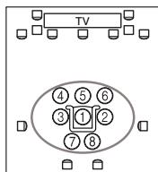
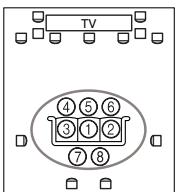
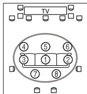
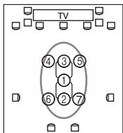
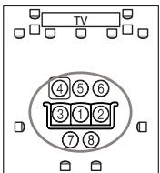
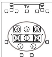
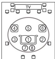
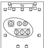
:listening area
①-⑧ :listening position
Using Audyssey MultEQ XT

ON/STANDBY
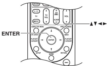
Notes:
- If the AV controller is muted, it will be unmuted automatically when Audyssey MultEQ XT Room Correction and Speaker Setup starts.
- Room correction and speaker setup cannot be performed while a pair of headphones is connected.
- It takes about 30 minutes to complete the room correction and speaker setup for eight positions. Total measurement time varies depending on the number of speakers.
- Do not disconnect the speaker setup microphone during the room correction and speaker setup, unless you want to cancel the setup.
- Do not connect or disconnect any speakers during the room correction and speaker setup.
1
Turn on the AV controller and the connected TV.
On the TV, select the input to which the AV controller is connected.
2

SETUP MIC
Set the speaker setup microphone at the Main Listening Position (page 56), and connect it to the SETUP MIC jack.
The speaker setting menu appears.
If you change "Speakers Type" settings, refer to step 4 on "Speaker Settings" (page 53).
In accordance with the connected speakers, set the "Front High/Front Wide Preout" setting to "Front High" or "Front Wide".
3

When you've finished, press the [ENTER] button.
![ONKYO PR-SC5507 - When you've finished, press the [ENTER] button. - 1](/content/2025/01/151815/images/06ade4bdd52061087a595ce83fe03d0bb270fa9df0859932e3543085a7410105.jpg)
Notes:
- Before starting Audyssey MultEQ XT Room Correction and Speaker Setup, arrange the room and connect the speakers as you would for enjoying movies. Changes to the room after auto setup requires you run the auto setup again, as room EQ characteristics may have changed.
- When starting the room correction and speaker setup, do not stand between the speakers and microphone, and avoid obstacles blocking the path between speakers and microphone. This will produce inaccurate results.
-
Position the microphone at ear height of a seated listener with the microphone tip pointed directly at the ceiling using a tripod. Do not hold the microphone in your hand during measurements as this will produce inaccurate results.
-
Make the room as quiet as possible. Background noise can disrupt the room measurements. Close windows, silence cell phones, televisions, radios, air conditioners, fluorescent lights, home appliances, light dimmers, or other devices.
- Cell phones should be turned off or placed away from all audio electronics during the measurement process as Radio Frequency Interference (RFI) may cause measurement disruptions (even if the cell phone is not in use).
Press [ENTER].
The room correction and speaker setup starts.
MultEQ XT: Auto Setup
Do not unplug setup microphone.
Please keep quiet.
Now measuring...
Test tones are played through each speaker as Audyssey MultEQ® XT Room Correction and Speaker Setup runs. This process takes a few minutes. Please refrain from talking during measurements and do not stand between speakers and the microphone.
The following screen appears.
MultEQ XT: Auto Setup
AUDY8SEY
Please place setup microphone at 2nd position at ear height.
Next
Place the setup microphone at the next position (page 56), and then press [ENTER].
Audyssey MultEQ XT performs more measurements. This takes a few minutes.
MultEQ XT: Auto Setup
Do not unplug setup microphone.
Please keep quiet.
Now measuring...
When prompted, place the setup microphone at the next position, and repeat step 5.
After the 3rd to the 8th measurement, the following screen appears.
MultEQ XT: Auto Setup
AUDYSSEY
Please select [Next], when measuring next position, and select [Finish], when ending.
Next
Finish(Calculate)
Use the Up and Down [A]/[V] buttons to select an option, and then press [ENTER].
Next:
Select "Next" to begin measuring the next measurement position. After the 8th measurement has been taken, the procedure automatically proceeds to step 8.
Finish(Calculate):
Select this if you don't want to measure any more listening positions and are ready to calculate the results, then go to step 8.
When the measurements are complete, the following screen appears.
MultEQ XT: Auto Setup
AUDYSSEY
Calculating...
□□□□□□□□□
9
When the calculations are complete, the following screen appears.

Use the Up and Down [A]/[V] buttons to select an option, and then press [ENTER].
The options are:
Save:
Save the calculated settings and exit the room correction and speaker setup.
Cancel:
Cancel the room correction and speaker setup.
Note:
You can view the calculated settings for the speaker configuration, speaker distances, and speaker levels by using the Left and Right [] / [] buttons.
10
If you selected "Save", the results are saved, and the following screen appears.
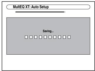
11
Disconnect the speaker setup microphone.
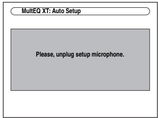
Notes:
- When the room correction and speaker setup is complete, the "Equalizer Settings" (page 92) will be set to "Audyssey" and "Dynamic EQ" (page 96) will be set to "On".
- You can cancel the Room Correction and Speaker Setup at any point in this procedure simply by disconnecting the setup microphone.
Error Messages
While the room correction and speaker setup is in progress, one of the following error messages may appear:
Ambient noise is too high.

This message appears if the background noise is too loud and the measurements cannot be performed properly.
Remove the source of the noise and try again.
Retry: Return to the measured point immediately before and start set up again.
Cancel: Cancel the room correction and speaker setup.
Speaker Detect Error
This message appears if a speaker is not detected. "Yes" means that a speaker was detected. "No" means that no speaker was detected.
Tip:
See "Speaker Configuration" (page 18) for appropriate settings.
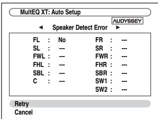
The front speaker has not been detected.
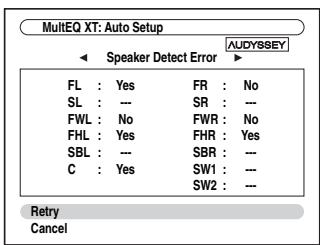
One of the front speakers has not been detected.
One of the front wide speakers has not been detected.
One of the front high speakers has not been detected.
One of the surround speakers has not been detected.
The surround back speakers have been detected but the surround speakers haven't.
The front high speakers have been detected but the surround speakers haven't.
The front wide speakers have been detected but the surround speakers haven't.
The right surround back speaker has been detected but the left surround back speaker hasn't.
The left surround back speaker has been detected but the surround speaker hasn't.
Subwoofer 2 has been detected but Subwoofer 1 has not.
The speaker type detected does not match what was expected. The speaker may be incorrect type or broken. Please check that it is the correct speaker type.
Speaker Matching Error!
The number of speakers detected on the second measurement and later was different to the number detected on the first measurement.
Make sure speakers that could not be detected are connected properly.
Retry: Return to step 2 and try again.
Cancel: Cancel the room correction and speaker setup.
Writing Error!
This message appears if saving fails.
Try saving again. If this message appears after 2 or 3 attempts, the AV controller is probably malfunctioning. Contact your Onkyo dealer.
Retry: Return to step 2 and try again.
Cancel: Cancel the room correction and speaker setup.
Changing the Speaker Settings Manually
If you wish to make changes to the settings found during the room correction and speaker setup, follow the directions on pages 90 to 93.
Notes:
- Please note that THX recommends any THX main speakers be set to "80Hz(THX)". If you set up your speakers using Audyssey MultEQ XT Room Correction and Speaker Setup, please make sure manually that any THX speakers are set to 80 Hz (THX) crossover (see page 90).
- Sometimes due to the electrical complexities of subwoofoers and the interaction with the room, THX recommends setting the level and the distance of the subwoofer manually.
- Sometimes due to interaction with the room, you may notice irregular results when setting the level and/or distance of the main speakers. If this happens, THX recommends setting them manually.
Using Powered Subwoofer
If you're using powered subwoofoers that output very low-frequency sound at a low volume level, it may not be detected by Audyssey MultEQ XT Room Correction and Speaker Setup.
If the "Subwoofer" appears on the "Review SP Configuration" screen as "No", increase the subwoofer's volume to the half-way point, set it to its highest crossover frequency, and then try running Audyssey MultEQ XT Room Correction and Speaker Setup again. Note that if the volume is set too high and the sound distorts, detection issues may occur, so use an appropriate volume level. If the subwoofer has a low-pass filter switch, set it to Off or Direct. Refer to your subwoofer's instruction manual for details.
Selecting the Input Source
This section explains how to select the input source (i.e., the AV component that you want to listen to or watch).
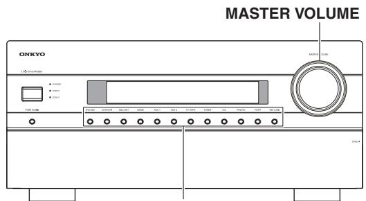
Input selector buttons
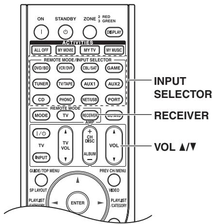
1
AV controller
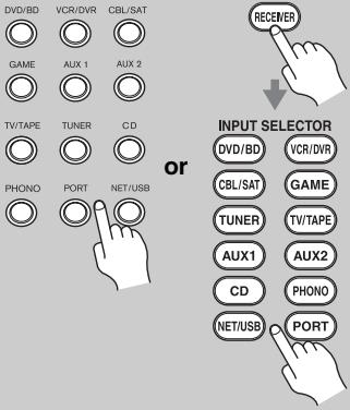
2
Use the AV controller's input selector buttons to select the input source.
To select the input source with the remote controller, press the [RECEIVER] button, and then press the INPUT SELECTOR buttons.
Start playback on the source component.
When you select DVD or another video component, on your TV, you'll need to select the video input that's connected to the AV controller's HDMI outputs, COMPONENT VIDEO MONITOR OUT or MONITOR OUT.
On some DVD players, you may need to turn on the digital audio output.
3
AV controller
or
Remote controller
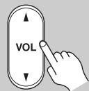
4
To adjust the volume, use the MASTER VOLUME control, or the remote controller's VOL [] / [] button.
The volume can be set to - dB, -81.5 dB through +18.0 dB (relative display).
The AV controller is designed for home theater enjoyment. It has a wide volume range, allowing precise adjustment.
The volume level can also be displayed as an absolute value. See "Volume Setup" on page 105.
Select a listening mode and enjoy!
See "Using the Listening Modes" on page 75.
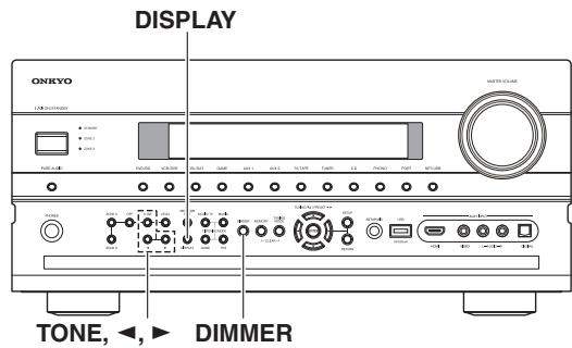
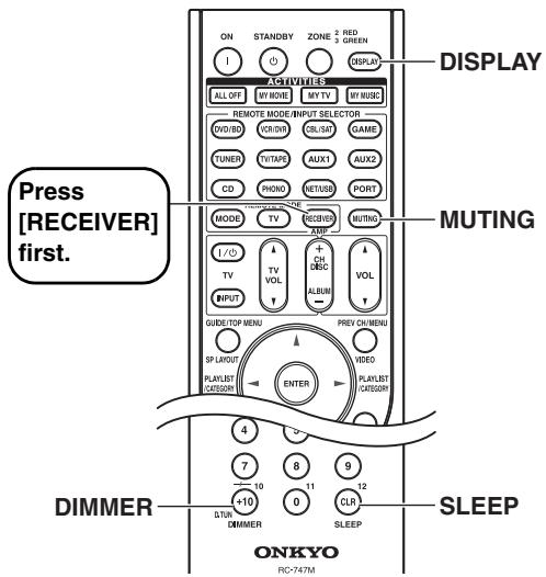
Adjusting the Bass & Treble
You can adjust the bass and treble for the front speakers, except when the Direct, Pure Audio or THX listening mode is selected.
| 1 AV controller TONE | Press the [TONE] button repeat- edly to select either “Bass” or “Treble” for each speaker or sub- woofer. |
| 2 AV controller | Use the Up [▶] and Down [▲] buttons to adjust. |
| Tip: This procedure can also be performed on the remote controller by using [AUDIO] button (see page 112). |
Bass
You can boost or cut low-frequency sounds output by the front speakers from -10dB to +10dB in 2 dB steps.
Treble
You can boost or cut high-frequency sounds output by the front speakers from -10dB to +10dB in 2 dB steps.
Notes:
- This setting is not available when the multichannel Analog input is selected.
- To bypass the bass and treble tone circuits, select the Direct, Pure Audio or THX listening mode.
Displaying Source Information
You can display various information about the current input source as follows.
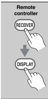
Press the [RECEIVER] button, and then press the [DISPLAY] button repeatedly to cycle through the available information.
Note:
This procedure can also be performed on the AV controller by using its [DISPLAY] button.
The following information can typically be displayed for input sources.
- If the input signal is analog, no format information is displayed. If the input signal is PCM, the sampling frequency is displayed. If the input signal is digital but not PCM, the signal format and the number of channels is displayed. For some digital input signals, including multichannel PCM, the signal format, number of channels, and sampling frequency is displayed. Information is displayed for about three seconds, then the previously displayed information reappears.
Setting the Display Brightness
You can adjust the brightness of the AV controller's display.
Remote controller
Press the [RECEIVER] button, and then press the [DIMMER] button repeatedly to select:
Normal + VOLUME light on.
Normal + VOLUME light off.
- Dim + VOLUME light off.
- Dimmer + VOLUME light off.
Alternatively, you can use the AV controller's [DIMMER] button (North American models).
Muting the AV Controller
You can temporarily mute the output of the AV controller.
Remote controller
Press the [RECEIVER] button, and then press the [MUTING] button.
The output is muted and the MUTING indicator flashes on the display, as shown.
![ONKYO PR-SC5507 - Press the [RECEIVER] button, and then press the [MUTING] button. - 1](/content/2025/01/151815/images/e9bde51e60e085f9be932f77252e6aac385fb83fdaa0c529420adc8a1ccbbf93.jpg)
To unmute the AV controller, press the [MUTING] button again, or adjust the volume.
The Mute function is cancelled when the AV controller is set to Standby.
Tip:
You can specify how much the output is muted with the "Muting Level" setting (page 105).
Using the Sleep Timer
With the sleep timer, you can set the AV controller to turn off automatically after a specified period.
Remote controller
Press the [RECEIVER] button, and then press the [SLEEP] button repeatedly to select the required sleep time.
The sleep time can be set from 90 to 10 minutes in 10 minute steps.
The SLEEP indicator appears on the display when the sleep timer has been set. The specified sleep time appears on the display for about five seconds, then the previous display reappears.
If you need to cancel the sleep timer, press the [SLEEP] button repeatedly until the SLEEP indicator disappears.
To check the time remaining until the AV controller sleeps, press the [SLEEP] button. Note that if you press the [SLEEP] button while the sleep time is being displayed, you'll shorten the sleep time by 10 minutes.
Using Headphones
You can connect a pair of stereo headphones (1/4-inch phone plug) to the AV controller's PHONES jack for private listening, as shown.
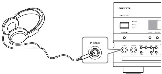
Notes:
- Always turn down the volume before connecting your headphones.
- While the headphones plug is inserted in the PHONES jack, the Headphone indicator, speaker/channel indicator FL and FR light up.
- When you connect a pair of headphones, the listening mode is set to Stereo, unless it's already set to Stereo, Mono, Direct, Pure Audio or DTS Surround Sensation.
- Listening mode automatically changes into DTS surround sensation when you connect a pair of headphones while DTS surround sensation mode is currently selected.
- The following listening modes can be used with headphones (the listening modes available also depend on the currently selected input source): Stereo, Direct, Pure Audio, Mono and DTS Surround Sensation.
Using Easy Macros
Using the Easy macro command in the Easy macro mode, you can sequentially operate Onkyo components with simple commands by simply pressing one button. These commands are user-specifiable (see page 144) and the default actions are described below. Press the ACTIVITIES buttons to start the Easy macro command. Once the AV controller has entered the normal macro mode, all of the ACTIVITIES buttons will automatically switch to the normal macro mode. In this case, pressing the [ALL OFF] button will set only the AV controller to Standby mode.
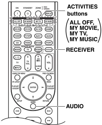
1
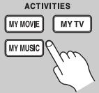
Press the [MY MOVIE], [MY TV], or [MY MUSIC] button.
MY MOVIE (default):
- The TV connected to the AV controller is turned on.
- The Onkyo DVD player connected to the AV controller is turned on.
- The AV controller is turned on.
- The input selector of the AV controller is set to "DVD/BD".
- The player starts playback. *1
MY TV (default):
- The TV connected to the AV controller is turned on.
- The cable set-top box connected to the AV controller is turned on.
- The AV controller is turned on.
- The input selector of the AV controller is set to "CBL/SAT". You can enjoy cable TV.
MY MUSIC (default):
- The Onkyo CD player connected to the AV controller is turned on.
- The AV controller is turned on.
- The input selector of the AV controller is set to "CD".
- The player starts playback.
Note:
Once you start the Easy macro command, you cannot use other ACTIVITIES buttons during the execution. If you want to operate other components halfway, press the [ALL OFF] to stop and press desired ACTIVITIES button.
2
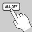
Press the [ALL OFF] button.
- The connected component stops and turns off.
- The AV controller turns off.
- The TV connected to the AV controller turns off (Standby).
1. Depending on the start-up time of the DVD/BD player, the AV controller may not activate this playback command. In this case, press the Play [▶] button on the remote controller.
2. When [MY MUSIC] is selected, with the default settings, this will not be performed.
*3. With some televisions, the power may not be turned off (or enter standby).
Changing Source Component
When you want to operate the component that is not assigned as the source component, you can assign it as the source component. For the default assignment, see page 145.
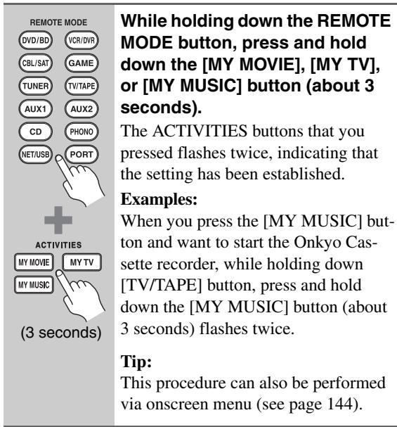
Restoring Default
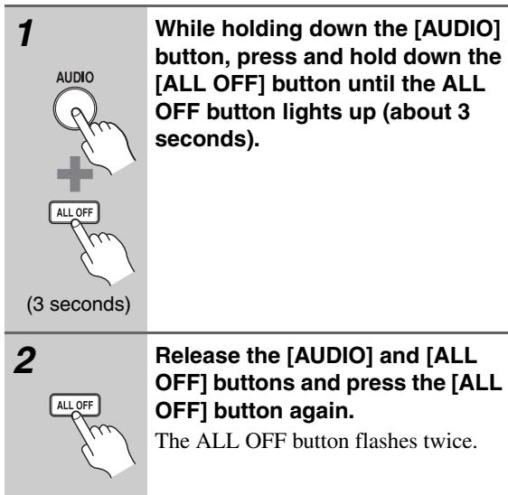
Using the Tuner
With the built-in tuner you can enjoy AM and FM radio stations. You can store your favorite stations as presets for quick selection.
Listening to the Radio

Use the [TUNER] input selector button to select either AM or FM.
In this example, FM has been selected. Each time you press the [TUNER] button, the input source changes between AM and FM.
![ONKYO PR-SC5507 - Use the [TUNER] input selector button to select either AM or FM. - 1](/content/2025/01/151815/images/2be55338663753e60989966cc5eed9610d5db06438182bbe9d4b5adf799242fb.jpg)
(Actual display depends on country.)
Tuning into Radio Stations
Auto Tuning Mode
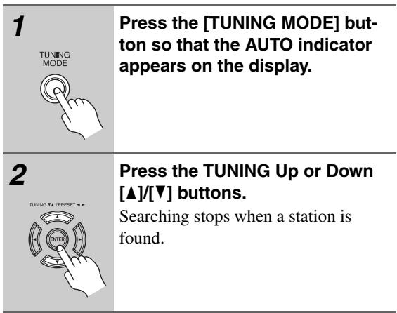
When tuned into a station, the TUNED indicator appears. When tuned into a stereo FM station, the FM STEREO indicator appears on the display, as shown.
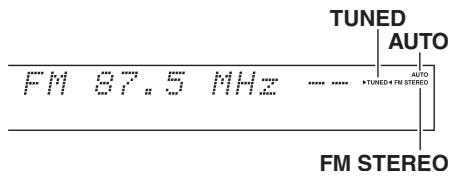
Manual Tuning Mode
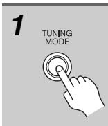
Press the [TUNING MODE] button so that the AUTO indicator disappears from the display.
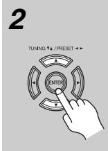
Press and hold the TUNING Up or Down [] / [] buttons.
The frequency stops changing when you release the button.
Press the buttons repeatedly to change the frequency one step at a time.
This model changes FM/AM frequency in 200k / 10k (or 50k / 9k) Hz steps.
In Manual Tuning mode, FM stations will be in mono.
Tuning into weak FM stereo stations
If the signal from a stereo FM station is weak, it may be impossible to get good reception. In this case, switch to Manual Tuning mode and listen to the station in mono.
Tuning into Stations by Frequency
You can tune into AM and FM stations directly by entering the appropriate frequency.
Press the [TUNER] button repeatedly to select AM or FM, followed by the [D.TUN] button.
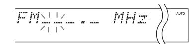
(Actual display depends on country.)
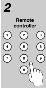
Within 8 seconds, use the number buttons to enter the frequency of the radio station.
For example, to tune to 87.5 (FM), press 8, 7, 5.
Presetting AM/FM Stations
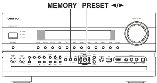
You can store a combination of up to 40 of your favorite AM/FM radio stations as presets.
1
Tune into the AM/FM station that you want to store as a preset.
2
Press the [MEMORY] button.
The preset number flashes.
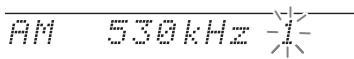
3
While the preset number is flashing (about 8 seconds), use the PRESET [] / [] buttons to select a preset from 1 through 40.
4
Press the [MEMORY] button again to store the station or channel.
The station or channel is stored and the preset number stops flashing.
Repeat this procedure for all of your favorite AM/FM radio stations.
Note:
You can name your radio presets for easy identification (see page 99). Its name is displayed instead of the band and frequency.
Selecting Presets
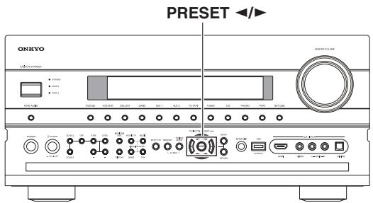
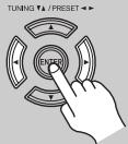
AV controller
or

Remote controller
or
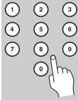
Remote controller
To select a preset, use the PRESET [] / [] buttons, or the remote controller's CH [+/-] button.
You can also use the remote controller's number buttons to select a preset directly.
Deleting Presets

MEMORY, TUNING MODE
1
Select the preset that you want to delete.
See the previous section.
2
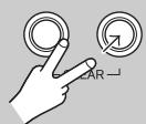
MEMORY
TUNING MODE
While holding down the [MEM-ORY] button, press the [TUNING MODE] button.
The preset is deleted and its number disappears from the display.
Using RDS (European models)
RDS only works in areas where RDS broadcasts are available.
When tuned into an RDS station, the RDS indicator appears.
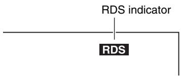
What is RDS?
RDS stands for Radio Data System and is a method of transmitting data in FM radio signals. It was developed by the European Broadcasting Union (EBU) and is available in most European countries. Many FM stations use it these days. In addition to displaying text information, RDS can also help you find radio stations by type (e.g., news, sport, rock, etc.).
The AV controller supports four types of RDS information:
PS (Program Service)
When tuned to an RDS station that's broadcasting PS information, the station's name will be displayed. Pressing the [DISPLAY] button will display the frequency for 3 seconds.
RT (Radio Text)
When tuned to an RDS station that's broadcasting text information, the text will be shown on the display (see page 70).
PTY (Program Type)
This allows you to search for RDS radio stations by type (see page 70).
TP (Traffic Program)
This allows you to search for RDS radio stations that broadcast traffic information (see page 70).
Notes:
-
In some cases, the text characters displayed on the AV controller may not be identical to those broadcast by the radio station. Also, unexpected characters may be displayed when unsupported characters are received. This is not a malfunction.
-
If the signal from an RDS station is weak, RDS data may be displayed intermittently or not at all.
RDS Program Types (PTY)
| Type | Display |
| None | None |
| News reports | News |
| Current affairs | Affairs |
| Information | Info |
| Sport | Sport |
| Education | Educate |
| Drama | Drama |
| Culture | Culture |
| Science and technology | Science |
| Varied | Varied |
| Pop music | Pop M |
| Rock music | Rock M |
| Middle of the road music | Easy M |
| Light classics | Light M |
| Serious classics | Classics |
| Other music | Other M |
| Weather | Weather |
| Finance | Finance |
| Children's programmes | Children |
| Social affairs | Social |
| Religion | Religion |
| Phone in | Phone In |
| Travel | Travel |
| Leisure | Leisure |
| Jazz music | Jazz |
| Country music | Country |
| National music | Nation M |
| Oldies music | Oldies |
| Folk music | Folk M |
| Documentary | Document |
| Alarm test | TEST |
| Alarm | Alarm! |
When tuned to an RDS station that's broadcasting text information, the text can be displayed.
Displaying Radio Text (RT)
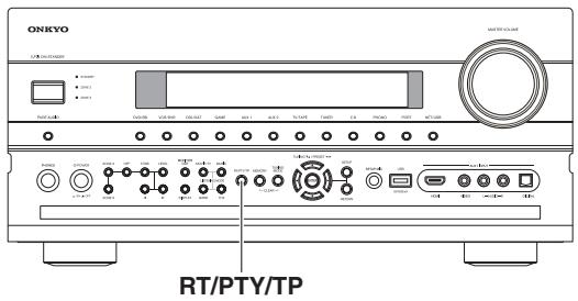
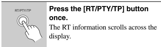
Notes:
- The message "Waiting" may appear while the AV controller waits for the RT information.
- If the message "No Text Data" appears on the display, no RT information is available.
Finding Stations by Type (PTY)
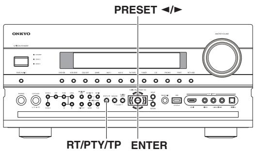
You can search for radio stations by type.
Listening to Traffic News (TP)
You can search for stations that broadcast traffic news.
About the UP-A1 Dock
With the UP-A1 Dock (sold separately), you can easily play the music, photo, or movie stored on your Apple iPod through the AV controller and enjoy great sound. You can use the AV controller's remote controller to operate your iPod.
For the latest information on the Dock, see the Onkyo Web site at: http://www.onkyo.com
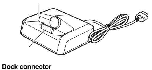
iPod adapter
Compatible iPod models
For information about which iPod models are supported by the UP-A1 Dock, see the UP-A1 Dock instruction manual.
Note:
Before using the UP-A1 Dock, update your iPod with the latest software, available from the Apple Web site.
Function Overview
Basic Operation
Note:
The AV controller may take several seconds to startup, so you might not hear the first few seconds of the first song.
- Auto Power On Function
If you start iPod playback while the AV controller is on Standby, the AV controller will automatically turn on and select your iPod as the input source.
- Direct Change Function
If you start iPod playback while listening to another input source, the AV controller will automatically select your iPod as the input source.
- Using the AV controller's Remote Controller
You can use the AV controller's remote controller to control basic iPod functions.
Operating Notes:
- Functionality depends on your iPod model and generation.
- Before selecting a different input source, stop iPod playback to prevent the AV controller from selecting the iPod input source by mistake.
- If any accessories are connected to your iPod, the AV controller may not be able to select the input source properly.
- While your iPod is in the UP-A1 Dock, its volume control has no effect. If you adjust your iPod models volume control while it's in the UP-A1 Dock, make sure it's not set too high before you reconnect your headphones.
- The Auto Power On function will not work if you set your iPod in the UP-A1 Dock while it is playing.
- When Zone 2 or 3 is turned on, you can't use Auto Power On and Direct Change functions.
Using Your iPod models Alarm Clock
You can use your iPod models Alarm Clock function to automatically turn on your iPod and the AV controller at a specified time. The AV controller's input source will automatically be set to the [PORT] selector.
Notes:
- To use this function, your iPod must be in the UP-A1 Dock, and the UP-A1 Dock must be connected to the AV controller.
- When you use this function, be sure to set the AV controller's volume control to a suitable level.
- The AV controller may take several seconds to startup, so you might not hear the first few seconds of the first song.
- When Zone 2 or 3 is turned on, you can't use this function.
- You cannot use this function for sound effects on your iPod.
Charging Your iPod models Battery
The UP-A1 Dock charges your iPod models battery while your iPod is in the UP-A1 Dock and connected to the UNIVERSAL PORT jacks on the AV controller.
While your iPod is seated in the UP-A1 Dock, its battery will be charged when the AV controller is set to "On" or "Standby".
Note:
When UP-A1 Dock that seated iPod is connected, the power consumption on standby mode slightly increases.
Controlling iPod
By pressing the REMOTE MODE button that's been programmed with the remote control code for your Dock, you can control your iPod in the Dock with the following buttons.
The [PORT] button is preprogrammed with the remote control code for controlling a Dock with Universal Port connector.
For details on entering a remote control code, see page 135.
When Using a Dock with Universal Port connector:
- Connect the Dock to the UNIVERSAL PORT jack.
- See the Dock's instruction manual for more information.
You can control your iPod when "PORT" is selected as the input source.
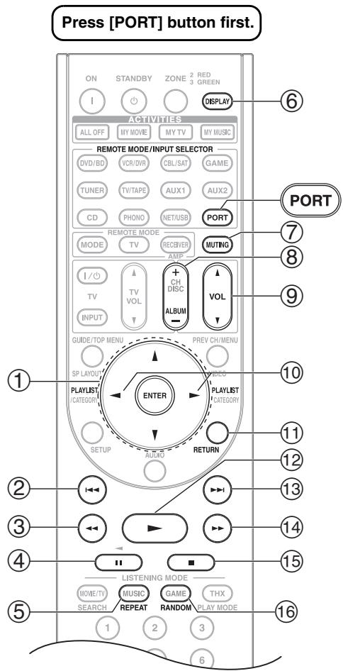
Notes:
- With some iPod models and generations, certain buttons may not work as expected.
- For detailed operation of the iPod, please refer to the instruction manual.
① Arrow [] / [] and ENTER buttons
Used to navigate menus and select items.
② Previous [1-4] button
Restarts the current song. Press it again to select the previous song.
③ Fast Reverse [< ] button
Press and hold to fast reverse.
④ Pause [I] button
Pauses playback. Press it again to start playback.
⑤ REPEAT button
Used with the repeat function.
⑥ DISPLAY button
Select Standard or Extended mode*1.
⑦ MUTING button (64)
Mutes or unmutes the AV controller.
⑧ ALBUM +/- button
Selects the next or previous album.
⑨ VOL [▲]/[▼] button (62)
Adjusts the volume of the AV controller.
10 PLAYLIST[/<]buttons
Selects the previous or next playlist on the iPod.
① RETURN button
Exits the menu or returns to the previous menu.
12 Play [▶] button
Starts playback. If the component is off, it will turn on automatically.
⑬ Next [▶i] button
Selects the next song.
Fast Forward [▶▶] button
Press and hold to fast forward.
15 Stop [■] button
Stops playback and displays a menu.
16 RANDOM button
Used with the shuffle function.
*1
Standard mode
Nothing is displayed on your TV and you navigate and select your contents by using your iPod's display.
Only this mode can playback the video.
Extended mode
Playlists (artists, albums, songs, and so on) are displayed on your TV, and you can navigate and select your music while looking at your TV.
Notes:
- In Extended mode, the playback will be continued even if the AV controller is turned off.
- In Extended mode, you cannot operate your iPod directly.
- In Extended mode, it may take some time to acquire the contents.
- In Extended mode, video contents can not display on your TV.
Status messages
PORT Reading
The AV controller is checking the connection with the dock.
PORT Not Support
The AV controller do not support the connected dock.
PORT UP-A1
UP-A1 Dock is connected.
Notes:
- The AV controller displays the message "UP-A1" for several seconds after recognizing the UP-A1.
- When the status message is not displayed on the AV controller's display, check the connection to your iPod.
This section explains how to record the selected input source to a component with recording capability, and how to record audio and video from different sources.
Notes:
- The surround sound and DSP listening modes cannot be recorded.
- Copy-protected DVDs cannot be recorded.
- Sources connected to a digital input cannot be recorded. Only analog inputs can be recorded.
- DTS signals will be recorded as noise, so don't attempt analog recording of DTS CDs or LDs.
- While the listening mode is set to Pure Audio, no image is provided because the power is turned off for the video circuit. If you want to make recordings, select other listening mode.
AV Recording
Audio sources can be recorded to a recorder (e.g., cassette deck, CDR, MD) connected to the TV/TAPE OUT jack. Video sources can be recorded to a video recorder (e.g., VCR, DVD recorder) connected to the VCR/DVR OUT jack. See pages 28 to 42 for hookup information.
| 1 DVD/BD GAME TV/TAPE PHONE ON your recorder, start recording. | Use the input selector buttons to select the source that you want to record. You can watch the source while recording. The AV controller's MASTER VOLUME control has no effect on recording. |
| 3 | On the source component, start playback. If you select another input source during recording, that input source will be recorded. |
Recording Separate AV Sources
Here you can record audio and video from completely separate sources, allowing you to overdub audio onto your video recordings. This function takes advantage of the fact that when an audio-only input source (i.e., TV/ TAPE, TUNER, CD or PHONO) is selected, the video input source remains unchanged.
In the following example, audio from the CD player connected to the CD IN, and video from the camcorder connected to the AUX1 INPUT VIDEO jack are recorded by the VCR connected to the VCR/DVR OUT jacks.
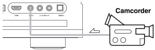
: video signal
:audio signal
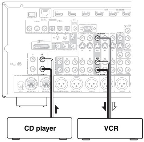
| 1 | Prepare the camcorder and CD player for playback. |
| 2 | Prepare the VCR for recording. |
| 3 | Press the [AUX 1] input selector button. |
| 4 | Press the [CD] input selector button. This selects the CD player as the audio source, but leaves the camcorder as the video source. |
| 5 | Start recording on the VCR and start play-back on the camcorder and CD player. The video from the camcorder and the audio from the CD player are recorded by the VCR. |
Selecting Listening Modes
See "About the Listening Modes" on page 83 for detailed information about the listening modes.
- The Dolby Digital and DTS listening modes can only be selected if your DVD player is connected to the AV controller with a digital audio connection (coaxial, optical, or HDMI).
- The listening modes you can select depend on the format of the input signal. To check the format, see "Displaying Source Information" on page 63.
- While a pair of headphones is connected, you can only select the Pure Audio, Mono, Direct, DTS Surround Sensation, or Stereo listening mode.

Selecting on the AV controller
LISTENING MODE
[PURE AUDIO] button
This button selects the Pure Audio listening mode. When this mode is selected, the AV controller's display is turned off and only video signals input through HDMI IN can be output. Pressing this button again will select the previous listening mode. This listening mode is not available while you are using Zone 2 ("Not Available" will appear on the display). If you turn Zone 2 on during the Pure Audio listening mode, the listening mode will change to Direct.
LISTENING MODE buttons
[MOVIE/TV] button
This button selects the listening modes intended for use with movies and TV.
[MUSIC] button
This button selects the listening modes intended for use with music.
[GAME] button
This button selects the listening modes intended for use with video games.
[THX] button
This button selects the THX listening modes.
![ONKYO PR-SC5507 - [THX] button - 1](/content/2025/01/151815/images/bd60627438a06e7bab18543739a8eb098e310eca2ba3b84394fb713c8317a092.jpg)
Selecting with the Remote Controller
![ONKYO PR-SC5507 - [THX] button - 2](/content/2025/01/151815/images/357446f2ee96480d09e5dce6649c12f1fcd997e159fd66824e3392ce6f7632f4.jpg)
Press the [RECEIVER] button, and then press the LISTENING MODE button repeatedly to select the listening mode.
LISTENING MODE buttons
[MOVIE/TV] button
This button selects the listening modes intended for use with movies and TV.
[MUSIC] button
This button selects the listening modes intended for use with music.
[GAME] button
This button selects the listening modes intended for use with video games.
[THX] button
This button selects the THX listening modes.
Listening Modes Available for Each Source Format
The Speaker layout illustration shows which speakers are set to active in the "Speaker Configuration" setting (see page 90).
The LISTENING MODE button illustration shows that listening modes can be selected.


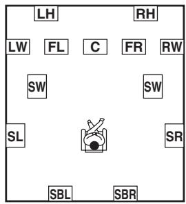
FL:Front left speaker
LW : Front wide left speaker
LH : Front high left speaker
C : Center speaker
RH : Front high right speaker
RW : Front wide right speaker
FR:Front right speaker
: Surround right speaker
SBR : Surround back right speaker
SBL : Surround back left speaker
SL : Surround left speaker
SW : Subwoofer
C:active in the speaker settings
C:non-active in the speaker settings
Mono/Multiplex Sources
: Available Listening Modes
| Listening Mode | Button | Speaker layout | |||||||||
| LH RW LW FL C FR RW SW SW SL SR SBL SBR | LH RW LW FL C FR RW SW SW SL SW SBL SBR | LH RW LW FL C FR RW SW SW SL SW SBL SBR | LH RW LW FL C FR RW SW SW SL SW SBL SBR | LH RW LW FL C FR RW SW SW SL SW SBL SBR | LH RW LW FL C FR RW SW SW SL SW SBL SBR | LH RW LH LW FL C FR RW SW SW SL SW SBL SBR | |||||
| Pure Audio*1 | PURE AUDIO | ✓ | ✓ | ✓ | ✓ | ✓ | ✓ | ||||
| Direct | MUSIC | ✓ | ✓ | ✓ | ✓ | ✓ | ✓ | ||||
| Stereo | MUSIC | ✓ | ✓ | ✓ | ✓ | ✓ | ✓ | ||||
| Mono | MUSIC | ✓ | ✓ | ✓ | ✓ | ✓ | ✓ | ||||
| Orchestra | MUSIC | ✓ | ✓ | ✓ | |||||||
| Unplugged | MUSIC | ✓ | ✓ | ✓ | |||||||
| Studio-Mix | MUSIC | ✓ | ✓ | ✓ | |||||||
| TV Logic | MUSIC | ✓ | ✓ | ✓ | |||||||
| Game-RPG | GAME | ✓ | ✓ | ✓ | |||||||
| Game-Action | GAME | ✓ | ✓ | ✓ | |||||||
| Game-Rock | GAME | ✓ | ✓ | ✓ | |||||||
| Game-Sports | GAME | ✓ | ✓ | ✓ | |||||||
| All Ch Stereo | MUSIC GAME | ✓ | ✓ | ✓ | ✓ | ✓ | |||||
| Full Mono | MUSIC GAME | ✓ | ✓ | ✓ | ✓ | ✓ | |||||
| T-D (Theater-Dimensional) | MUSIC GAME | ✓ | ✓ | ✓ | ✓ | ✓ | ✓ | ||||
| DTS Surround Sensation | MUSIC GAME | ✓ | ✓ | ✓ | ✓ | ✓ | ✓ | ||||
Notes:
*1 This listening mode is not available while you are using Zone 2 ("Not Available" will appear on the display). If you turn Zone 2 on during the Pure Audio listening mode, the listening mode will change to Direct.
- Available sampling rate for PCM input signal is 32/44.1/48/88.2/96/176.4/192kHz.
- The listening modes cannot be selected with some source formats.
Stereo Source (1/2)
: Available Listening Modes
| Listening Mode | Button | Speaker layout | |||||
| LH IRH LW FL C FR RW SW SW SL SR SBL SBR | LH IRH LW FL C FR RW SW SW SL SR SBL SBR | LH IRH LW FL C FR RW SW SW SL SR SBL SBR | LH IRH LW FL C FR RW SW SW SL SR SBL SBR | ||||
| Pure Audio*3 | PURE AUDIO | ✓ | ✓ | ✓ | ✓ | ||
| Direct | MUSIC | ✓ | ✓ | ✓ | ✓ | ||
| Stereo | MUSIC | ✓ | ✓ | ✓ | ✓ | ||
| Mono | MUSIC | ✓ | ✓ | ✓ | ✓ | ||
| PLII/PLIIx Movie*1 | MUSIC | ✓ | ✓ | ✓ | |||
| PLII/PLIIx Music*1 | MUSIC | ✓ | ✓ | ✓ | |||
| PLII/PLIIx Game*1 | GAME | ✓ | ✓ | ✓ | |||
| PLIIz Height | MUSIC | ✓ | |||||
| Neo:6 Cinema | MUSIC | ✓ | ✓ | ✓ | |||
| Neo:6 Music | MUSIC | ✓ | ✓ | ✓ | |||
| Neural Surround | MUSIC | ✓ | ✓ | ✓ | |||
| Neural Digital Music | MUSIC | ✓ | ✓ | ✓ | |||
| PLII/PLIIx Movie*1 THX Cinema | MUSIC | ✓ | ✓ | ||||
| PLII/PLIIx Movie Audyssey DSX*2 | MUSIC | ✓ | |||||
| PLIIz Height THX Cinema | MUSIC | ✓ | |||||
| Neo:6 Cinema THX Cinema | MUSIC | ✓ | ✓ | ||||
| Neo:6 Cinema Audyssey DSX*2 | MUSIC | ✓ | |||||
| Neural THX Cinema | MUSIC | ✓ | ✓ | ||||
| PLII/PLIIx Music*1 THX Music | MUSIC | ✓ | ✓ | ||||
| PLII/PLIIx Music Audyssey DSX*2 | MUSIC | ✓ | |||||
| PLIIz Height THX Music | MUSIC | ✓ | |||||
| Neo:6 Music THX Music | MUSIC | ✓ | ✓ | ||||
| Neo:6 Music Audyssey DSX*2 | MUSIC | ✓ | |||||
| Neural Digital Music THX Music | MUSIC | ✓ | ✓ | ||||
Stereo Source (2/2)
: Available Listening Modes
| Listening Mode | Button | Speaker layout | ||||||||
| LH | RH | LH | RH | LH | ||||||
| LW | FL | C | FR | RW | LW | FL | C | FR | ||
| SW | SW | SW | SW | SW | ||||||
| SL | SR | SL | SR | SL | ||||||
| SBL | SBR | SBR | SBL | SBR | SBL | |||||
| PLII/PLIIx Game*1THX Games | GAME THX | ✓ | ✓ | |||||||
| PLII/PLIIx Game Audyssey DSX*2 | GAME | ✓ | ||||||||
| PLIIz HeightTHX Games | GAME THX | ✓ | ||||||||
| Neural THX Games | GAME THX | ✓ | ✓ | |||||||
| PLII Game THX Ultra2 Games | GAME THX | ✓ | ||||||||
| PLIIz HeightTHX Ultra2 Games | GAME THX | ✓ | ||||||||
| Orchestra | MUSIC | ✓ | ✓ | |||||||
| Unplugged | MUSIC | ✓ | ✓ | |||||||
| Studio-Mix | MUSIC | ✓ | ✓ | |||||||
| TV Logic | MOVE/TV | ✓ | ✓ | |||||||
| Game-RPG | GAME | ✓ | ✓ | |||||||
| Game-Action | GAME | ✓ | ✓ | |||||||
| Game-Rock | GAME | ✓ | ✓ | |||||||
| Game-Sports | GAME | ✓ | ✓ | |||||||
| All Ch Stereo | MOVE/TV MUSIC GAME | ✓ | ✓ | ✓ | ||||||
| Full Mono | MOVE/TV MUSIC GAME | ✓ | ✓ | ✓ | ||||||
| T-D (Theater-Dimensional) | MOVE/TV GAME | ✓ | ✓ | ✓ | ✓ | |||||
| Neo:6 Cinema DTS Surround Sensation | MOVE/TV GAME | ✓ | ✓ | ✓ | ✓ | |||||
| Neo:6 Music DTS Surround Sensation | MUSIC | ✓ | ✓ | ✓ | ✓ | |||||
Notes:
1 If there are no surround back speakers, Dolby Pro Logic II is used.
2 This listening mode can be selected only when all the following conditions are satisfied:
a. Center speaker is connected to the power amplifier.
b. Either of Front High speakers or Front Wide speakers is connected to the power amplifier.
*3 This listening mode is not available while you are using Zone 2 ("Not Available" will appear on the display). If you turn Zone 2 on during the Pure Audio listening mode, the listening mode will change to Direct.
Available sampling rate for PCM input signal is 32/44.1/48/88.2/96/176.4/192kHz.
- The listening modes cannot be selected with some source formats.
5.1 channel Sources (1/3)
: Available Listening Modes
| Listening Mode | Button | Speaker layout | ||||
| LH IRH LW FL C FR RW SW SW SL SR SBL SBR | LH IRH LW FL C FR RW SW SW SL SR SBL SBR | LH IRH LW FL C FR RW SW SW SL SR SBL SBR | LH IRH LW FL C FR RW SW SW SL SR SBL SBR | |||
| Pure Audio*3 | PURE AUDIO MUSIC | ✓ | ✓ | ✓ | ✓ | |
| Direct | MOVETV MUSIC GAME | ✓ | ✓ | ✓ | ✓ | |
| Stereo | MUSIC | ✓ | ✓ | ✓ | ✓ | |
| Mono | MOVETV | ✓ | ✓ | ✓ | ✓ | |
| DolbyDigital/DolbyDigital Plus/TrueHD/ Multichannel/ DTS/ DTS 96/24*4/ DTS Express/ DTS-HD High Resolution Audio/DTS-HD Master Audio/ DSD*1 | MOVETV MUSIC GAME | ✓ | ✓ | ✓ | ||
| PLIIx Movie | MOVETV | ✓ | ||||
| PLIIx Music | MUSIC | ✓ | ||||
| PLIIz Height | MOVETV MUSIC GAME | ✓ | ||||
| DolbyEX | MOVETV MUSIC GAME | ✓ | ||||
| DolbyEX Audyssey DSX | MUSIC | ✓ | ||||
| Neo:6 | MOVETV MUSIC GAME | ✓ | ||||
| Neo:6 Audyssey DSX | MOVETV MUSIC GAME | ✓ | ||||
| Neural Surround | MOVETV | ✓ | ||||
| Audyssey DSX*2 | MOVETV MUSIC GAME | ✓ | ||||
| THX Cinema | MOVETV THX | ✓ | ✓ | |||
| PLIIx Movie THX Cinema | MOVETV THX | ✓ | ||||
| PLIIx Movie Audyssey DSX | MOVETV | ✓ | ||||
| PLIIz Height THX Cinema | MOVETV THX | ✓ | ||||
| Neo:6 THX Cinema | MOVETV THX | ✓ | ||||
| Neural THX Cinema | MOVETV THX | ✓ | ||||
| THX Music | MUSIC THX | ✓ | ✓ | |||
5.1 channel Sources (2/3)
: Available Listening Modes
| Listening Mode | Button | Speaker layout | |||||||||
| LH | RH | LH | RH | LH | RH | ||||||
| LW | FL | C | FR | RW | LW | FL | C | FR | RW | ||
| SW | SW | SW | SW | SW | |||||||
| SL | SR | SR | SL | SR | |||||||
| SBL | SBR | SBR | SBL | SBR | SBL | SBR | |||||
| PLIIx Music THX Music | MUSIC | THX | ✓ | ||||||||
| PLIIx Music Audyssey DSX | MUSIC | ✓ | |||||||||
| PLIIz Height THX Music | MUSIC | THX | ✓ | ||||||||
| Neo:6 THX Music | MUSIC | THX | ✓ | ||||||||
| Neural THX Music | MUSIC | THX | ✓ | ||||||||
| THX Games | GAME | THX | ✓ | ✓ | |||||||
| PLIIx Height THX Games | GAME | THX | ✓ | ||||||||
| Neo:6 THX Games | GAME | THX | ✓ | ||||||||
| Neural THX Games | GAME | THX | ✓ | ||||||||
| THX Surround EX | MOE/TV | THX | ✓ | ||||||||
| THX Ultra2 Cinema | MOE/TV | THX | ✓ | ||||||||
| PLIIz THX Ultra2 Cinema | MOE/TV | THX | ✓ | ||||||||
| THX Ultra2 Music | MUSIC | THX | ✓ | ||||||||
| PLIIz THX Ultra2 Music | MUSIC | THX | ✓ | ||||||||
| THX Ultra2 Games | GAME | THX | ✓ | ||||||||
| PLIIz THX Ultra2 Games | GAME | THX | ✓ | ||||||||
| Orchestra | MUSIC | ✓ | ✓ | ||||||||
| Unplugged | MUSIC | ✓ | ✓ | ||||||||
| Studio-Mix | MUSIC | ✓ | ✓ | ||||||||
| TV Logic | MOE/TV | ✓ | ✓ | ||||||||
| Game-RPG | GAME | ✓ | ✓ | ||||||||
| Game-Action | GAME | ✓ | ✓ | ||||||||
| Game-Rock | GAME | ✓ | ✓ | ||||||||
| Game-Sports | GAME | ✓ | ✓ | ||||||||
| All Ch Stereo | MOE/TV | MUSIC | GAME | ✓ | ✓ | ✓ | |||||
| Full Mono | MOE/TV | MUSIC | GAME | ✓ | ✓ | ✓ | |||||
5.1 channel Sources (3/3)
: Available Listening Modes
| Listening Mode | Button | Speaker layout | |||||||||||||||||||||
| LH | RH | LH | RH | LH | RH | LH | RH | ||||||||||||||||
| LW | FL | C | FR | RW | LW | FL | C | FR | RW | LW | FL | C | FR | RW | LW | FL | C | FR | RW | ||||
| SW | SW | SW | SW | SW | SW | SW | SW | ||||||||||||||||
| SL | SR | SL | SR | SL | SR | SL | SR | ||||||||||||||||
| SBL | SBR | SBL | SBR | SBL | SBR | SBL | SBR | ||||||||||||||||
| T-D (Theater-Dimensional) | MOE(TY) GAME | ✓ | ✓ | ✓ | ✓ | ||||||||||||||||||
| DTS Surround Sensation | MOE(TY) MUSIC GAME | ✓ | ✓ | ✓ | ✓ | ||||||||||||||||||
Notes:
1 AV controller can input the DSD signal from HDMI IN. Setting the output setting on the player side to PCM might obtain a better sound according to the player. In that case, set the output setting on the player side to PCM.
2 This listening mode can be selected only when all the following conditions are satisfied: a. Center speaker is connected to the power amplifier. b. Either of Front High speakers or Front Wide speakers is connected to the power amplifier.
3 This listening mode is not available while you are using Zone 2 ("Not Available" will appear on the display). If you turn Zone 2 on during the Pure Audio listening mode, the listening mode will change to Direct.
4 Depending on the input source, DTS is used.
Available sampling rate for PCM input signal is 32/44.1/48/88.2/96/176.4/192kHz.
- The listening modes cannot be selected with some source formats.
7.1 channel Sources
: Available Listening Modes
| Listening Mode | Button | Speaker layout | ||||||||
| LH | RH | LH | RH | LH | ||||||
| LW | FL | C | FR | RW | LW | FL | C | FR RW | ||
| SW | SW | SW | SW | SW | ||||||
| SL | SR | SL | SR | SL | ||||||
| SBL | SBR | SBL | SBR | SBL | ||||||
| Pure Audio*3 | PURE AUDIO | ✔ | ✔ | ✔ | ||||||
| Direct | MUSIC | ✔ | ✔ | ✔ | ||||||
| Stereo | MUSIC | ✔ | ✔ | ✔ | ||||||
| Mono | MUSIC | ✔ | ✔ | ✔ | ||||||
| Multichannel/DolbyDigitalPlus/TrueHD/DTS-HD HighResolutionAudio/DTS-HDMaster Audio/DTS-ESDiscrete*4/DTS-ES Matrix*4 | MUSIC | ✔ | ✔ | ✔*1 | ||||||
| PLlZ Height | MUSIC | ✔ | ✔ | |||||||
| Audyssey DSX*2 | MUSIC | ✔ | ✔ | |||||||
| THX Cinema | MUSIC | THX | ✔ | |||||||
| PLlZ HeightTHX Cinema | MUSIC | THX | ✔ | |||||||
| THX Music | MUSIC | THX | ✔ | |||||||
| PLlZ HeightTHX Music | MUSIC | THX | ✔ | |||||||
| THX Games | GAME | THX | ✔ | |||||||
| PLlZ HeightTHX Games | GAME | THX | ✔ | |||||||
| Orchestra | MUSIC | ✔ | ||||||||
| Unplugged | MUSIC | ✔ | ||||||||
| Studio-Mix | MUSIC | ✔ | ||||||||
| TV Logic | MUSIC | ✔ | ||||||||
| Game-RPG | GAME | ✔ | ||||||||
| Game-Action | GAME | ✔ | ||||||||
| Game-Rock | GAME | ✔ | ||||||||
| Game-Sports | GAME | ✔ | ||||||||
| All Ch Stereo | MUSIC | ✔ | ✔ | ✔ | ||||||
| Full Mono | MUSIC | ✔ | ✔ | ✔ | ||||||
| T-D (Theater-Dimensional) | MUSIC | ✔ | ✔ | ✔ | ||||||
| DTS SurroundSensation | MUSIC | ✔ | ✔ | ✔ | ||||||
Notes:
1 Based on the audio channels contained in the source, the corresponding speakers will output the sound.
2 This listening mode can be selected only when all the following conditions are satisfied: a. Center speaker is connected to the power amplifier. b. Either of Front High speakers or Front Wide speakers is connected to the power amplifier.
3 This listening mode is not available while you are using Zone 2 ("Not Available" will appear on the display). If you turn Zone 2 on during the Pure Audio listening mode, the listening mode will change to Direct.
4 If there are no surround back speakers, DTS is used.
Available sampling rate for PCM input signal is 32/44.1/48/88.2/96/176.4/192kHz.
- The listening modes cannot be selected with some source formats.
About the Listening Modes
The AV controller's listening modes can transform your listening room into a movie theater or concert hall, with high fidelity and stunning surround sound.
Pure Audio
In this mode, the display and video circuitry are turned off, minimizing possible noise sources for the ultimate in high-fidelity reproduction. (As the video circuitry is turned off, only video signals input through HDMI IN can be output.)
Direct
In this mode, audio from the input source is output directly with minimal processing, providing high-fidelity reproduction. All of the source's audio channels are output as they are.
Stereo
Sound is output by the front left and right speakers and subwoofer.
Mono
Use this mode when watching an old movie with a mono soundtrack, or use it with the foreign language soundtracks recorded in the left and right channels of some movies. It can also be used with DVDs or other sources containing multiplexed audio, such as karaoke DVDs.
Multichannel
This mode is for use with PCM multichannel sources.
Dolby Pro Logic IIx
Dolby Pro Logic II
Dolby Pro Logic IIx expands any 2-channel source for 7.1-channel playback. It provides a very natural and seamless surround-sound experience that fully envelops the listener. As well as music and movies, video games can also benefit from the dramatic spatial effects and vivid imaging. If you're not using any surround back speakers, Dolby Pro Logic II will be used instead of Dolby Pro Logic IIx.
- Dolby PLIIx Movie
Use this mode with any stereo or Dolby Surround (Pro Logic) movie (e.g., TV, DVD, VHS).
- Dolby PLIIx Music
Use this mode with any stereo or Dolby Surround (Pro Logic) music source (e.g., CD, radio, cassette, TV, VHS, DVD).
- Dolby PLIIx Game
Use this mode with video games, especially those that bear the Dolby Pro Logic II logo.
Dolby Pro Logic IIz Height
Dolby Pro Logic IIz Height is designed to more effectively use existing program material when height channel speaker outputs are present. Dolby Pro Logic IIz
Height can be used to upmix a variety of sources from movies and music, but are particularly well-suited to upmix game content.
Dolby Digital
Use this mode with DVDs that bear the Dolby Digital logo, and Dolby Digital TV broadcasts. This is the most common digital surround-sound format, and it'll put you right in the middle of the action, just like being in a movie theater or concert hall.
Audyssey Dynamic Surround Expansion™
Audyssey Dynamic Surround Expansion™ is a scalable system that adds new speakers to improve surround impression. Starting with a 5.1 system Dynamic Surround Expansion first adds Wide channels for the biggest impact on envelopment. Research in human hearing has proven that information from the Wide channels is much more critical in the presentation of a realistic soundstage than then Back Surround channels found in traditional 7.1 systems. Dynamic Surround Expansion then creates a pair of Height channels to reproduce the next most important acoustical and perceptual cues. In addition to these new Wide and Height channels, Dynamic Surround Expansion applies Surround Envelopment Processing to enhance the blend between the front and surround channels.
5.1-channel source + Dolby EX
These modes expand 5.1-channel sources for 6.1/7.1-channel playback. They're especially suited to Dolby EX soundtracks that include a matrix-encoded surround back channel. The additional channel adds an extra dimension and provides an enveloping surround sound experience, perfect for rotating and fly-by sound effects.
Dolby Digital Plus
Developed for use with HDTV, including the new video disc formats Blu-ray and HD DVD, this is the latest multichannel audio format from Dolby. It supports up to 7.1 channels with 48kHz sampling rate.
Dolby TrueHD
Designed to take full advantage of the additional storage space offered by the new Blu-ray and HD DVD disc formats, this new Dolby format offers up to 7.1 discrete channels of digital audio with 48/96kHz , up to 5.1-channels with 192kHz sampling rate.
5.1-channel source + Dolby PLIIx Music
These modes use the Dolby Pro Logic IIx Music mode to expand 5.1-channel sources for 6.1/7.1-channel playback.
5.1-channel source + Dolby PLIIx Movie
These modes use the Dolby Pro Logic IIx Movie mode to expand 5.1-channel sources for 7.1-channel playback.
DTS
The DTS digital surround-sound format supports up to 5.1 discrete channels and uses less compression for high-fidelity reproduction. Use it with DVDs and CDs that bear the DTS logo.
DTS 96/24
This mode is for use with DTS 96/24 sources. This is high-resolution DTS with a 96kHz sampling rate and 24-bit resolution, providing superior fidelity. Use it with DVDs that bear the DTS 96/24 logo.
DTS-ES Discrete
This mode is for use with DTS-ES Discrete soundtracks, which use a discrete surround back channel for true 6.1/7.1-channel playback. The seven totally separate audio channels provide better spatial imaging and 360-degree sound localization, perfect for sounds that pan across the surround channels. Use it with DVDs that bear the DTS-ES logo, especially those with a DTS-ES Discrete soundtrack.
DTS-ES Matrix
This mode is for use with DTS-ES Matrix soundtracks, which use a matrix-encoded back-channel for 6.1/7.1-channel playback. Use it with DVDs that bear the DTS-ES logo, especially those with a DTS-ES Matrix soundtrack.
DTS Neo:6
This mode expands any 2-channel source for up to 7.1-channel playback. It uses seven full-bandwidth channels of matrix decoding for matrix-encoded material, providing a very natural and seamless surround sound experience that fully envelops the listener.
Neo:6 Cinema
Use this mode with any stereo movie (e.g., TV, DVD, VHS).
Neo:6 Music
Use this mode with any stereo music source (e.g., CD, radio, cassette, TV, VHS, DVD).
5.1-channel source + Neo:6
This mode uses Neo:6 to expand 5.1-channel sources for 6.1/7.1-channel playback.
DTS-HD High Resolution Audio
Developed for use with HDTV, including the new video disc formats Blu-ray and HD DVD, this is the latest multichannel audio format from DTS. It supports up to 7.1 channels with 96kHz sampling rate.
DTS-HD Master Audio
Designed to take full advantage of the additional storage space offered by the new Blu-ray and HD DVD disc formats, this new DTS format offers up to 7.1 discrete channels of digital audio with 48/96kHz , up to 5.1-channels with 192kHz sampling rate.
DTS Express
This format supports up to 5.1 channels and a lower sampling rate of 48kHz . Applications include interactive audio and commentary encoding for HD DVD Sub Audio and Blu-ray Secondary Audio. Also broadcast and media servers.
Neural Digital Music
Neural Digital Music is a new surround mode specifically designed to enhance the playback of compressed digital music content. It provides listeners with an expanded sound stage and clean surround experience, even with compressed audio sources such as MP3s and Internet streams.
DSD
DSD stands for Direct Stream Digital and is the format used to store digital audio on Super Audio CDs (SACD). This mode can be used with Super Audio CDs that feature multichannel audio.
DTS Surround Sensation Speaker
With this mode you can enjoy a virtual 5.1 surround sound even with only two speakers.
- Neo:6 Cinema + DTS Surround Sensation
Neo:6 Music + DTS Surround Sensation
These modes use Neo:6 to expand stereo sources for virtual surround playback.
DTS Surround Sensation Headphone
DTS Surround Sensation Headphone delivers simulated virtual multi-channel surround sound through any stereo headphones.
THX
Founded by George Lucas, THX develops stringent standards that ensure movies are reproduced in movie theaters and home theaters just as the director intended. THX Modes carefully optimize the tonal and spatial characteristics of the soundtrack for reproduction in the home-theater environment. They can be used with 2-channel matrixed and multichannel sources.
Surround back speaker output depends on the source material and the selected listening mode.
THX Cinema
THX Cinema mode corrects theatrical soundtracks for playback in a home theater environment. In this mode, THX Loudness Plus is configured for cinema levels and Re-EQ, Timbre Matching, and Adaptive Decorrelation are active.
THX Music
THX Music mode is tailored for listening to music, which is typically mastered at significantly higher levels than movies. In this mode, THX Loudness Plus is configured for music playback and only Timbre Matching is active.
- THX Games
THX Games mode is meant for spatially accurate playback of game audio, which is often mixed similarly to movies but in a smaller environment. THX Loudness Plus is configured for game audio levels, with Timbre Matching active.
THX Ultra2 Cinema
This mode expands 5.1-channel sources for 7.1-channel playback. It does this by analyzing the composition of the surround source, optimizing the ambient and directional sounds to produce the surround back channel output.
- THX Ultra2 Music
This mode is designed for use with music. It expands 5.1-channel sources for 7.1-channel playback.
- THX Ultra2 Games
This mode is designed for use with video games. It can expand 5.1-channel sources for 6.1/7.1-channel playback.
THX Surround EX
This mode expands 5.1-channel sources for 6.1/7.1-channel playback. It's especially suited to Dolby Digital EX sources. THX Surround EX, also known as Dolby Digital Surround EX, is a joint development between Dolby Laboratories and THX Ltd.
Neural Surround
Neural Surround employs psychoacoustic frequency domain processing, which allows delivery of a more detailed sound stage, with superior channel separation and localization of audio elements. The Neural Surround modes can expand any 2-channel stereo source for 5.1- or 7.1-channel playback, respectively. Use them with CD, radio, cassette, TV, VHS, DVD, and other 2-channel
stereo sources, including video games. Neural Surround can also be used by broadcasters to encode and transmit surround-sound content over a stereo signal, which listeners can enjoy as either surround sound or normal stereo.
Onkyo Original DSP Modes
Orchestra
Suitable for classical or operatic music, this mode emphasizes the surround channels in order to widen the stereo image, and simulates the natural reverberation of a large hall.
Unplugged
Suitable for acoustic instruments, vocals, and jazz, this mode emphasizes the front stereo image, giving the impression of being right in front of the stage.
Studio-Mix
Suitable for rock or pop music, listening to music in this mode creates a lively sound field with a powerful acoustic image, like being at a club or rock concert.
TV Logic
This mode adds realistic acoustics to TV shows produced in a TV studio, surround effects to the entire sound, and clarity to voices.
Game-RPG
Use this mode when playing role playing game discs.
Game-Action
Use this mode when playing action game discs.
Game-Rock
Use this mode when playing rock game discs.
Game-Sports
Use this mode when playing sports game discs.
All Ch Stereo
Ideal for background music, this mode fills the entire listening area with stereo sound from the front, surround, and surround back speakers.
Full Mono
In this mode, all speakers output the same sound in mono, so the sound you hear is the same regardless of where you are within the listening room.
T-D (Theater-Dimensional)
With this mode you can enjoy a virtual surround sound even with only two or three speakers. This works by controlling how sounds reach the listener's left and right ears. Good results may not be possible if there's too much reverb, so we recommend that you use this mode in an environment with little or no natural reverb.
Onscreen Setup Menus
The onscreen setup menus appear on the connected TV and provide a convenient way to change the AV controller's various settings. Settings are organized into nine categories on the main menu, most containing a submenu.
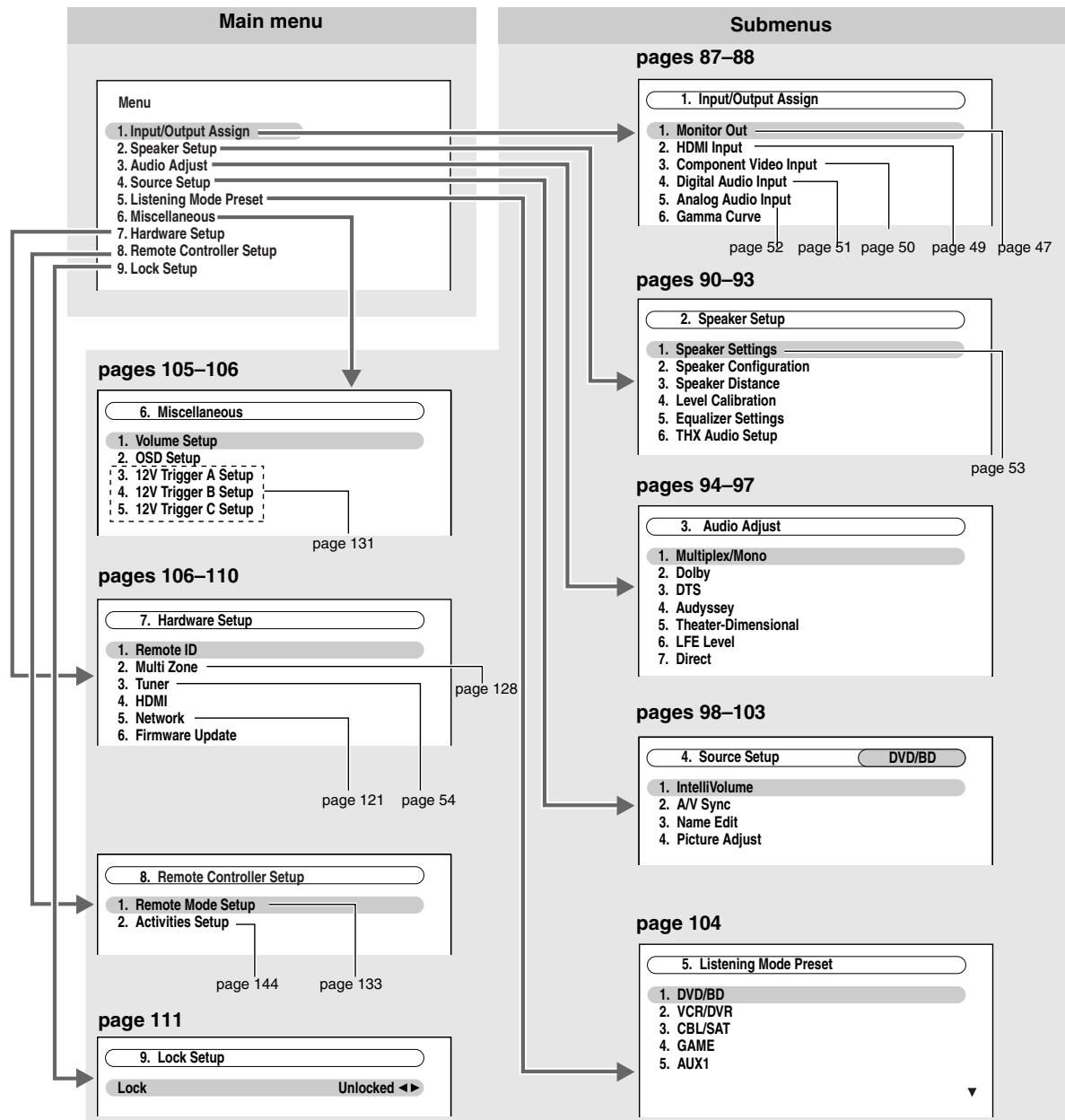
Input/Output Assign
This section explains items on the "Input/Output Assign" menu.
Press the [RECEIVER] button followed by the [SETUP] button.
The main menu appears onscreen.
If the main menu doesn't appear, make sure the appropriate external input is selected on your TV.
2 Use the Up and Down [] / [] buttons to select "1. Input/Output Assign", and then press [ENTER].
3 Use the Up and Down [ ] / [ ] buttons to select the submenu, and then press [ENTER].
4 Use the Up and Down [A]/[▼] buttons to select setting, and then use the Left and Right [▲]/[▶] buttons to set them.
5 When you've finished, press the [SETUP] button.
The setup menu closes.
Note:
This procedure can also be performed on the AV controller by using its [SETUP] button, arrow buttons, and [ENTER] button.
Monitor Out
| Monitor Out Resolution | See “Monitor Out Setup” on page 47. |
| Brightness | -50 to +50 (default: 0) |
| With this setting you can adjust the picture brightness. “-50” is the darkest. “+50” is the brightest. | |
| Contrast | -50 to +50 (default: 0) |
| With this setting you can adjust contrast. “-50” is the least. “+50” is the greatest. | |
| Hue | -20 to +20 (default: 0) |
| With this setting you can adjust the red/green balance. “-20” is the strongest green. “+20” is the strongest red. | |
| Saturation | -50 to +50 (default: 0) |
| With this setting you can adjust saturation. “-50” is the weakest color. “+50” is the strongest color. | |
| Red Brightness | -50 to +50 (default: 0) |
| With this setting you can adjust the picture red brightness. “-50” is the darkest. “+50” is the brightest. | |
| Red Contrast | -50 to +50 (default: 0) |
| With this setting you can adjust red contrast. “-50” is the least. “+50” is the greatest. | |
| Green Brightness | -50 to +50 (default: 0) |
| With this setting you can adjust the picture green brightness. “-50” is the darkest. “+50” is the brightest. | |
| Green Contrast | -50 to +50 (default: 0) |
| With this setting you can adjust green contrast. “-50” is the least. “+50” is the greatest. | |
| Blue Brightness | -50 to +50 (default: 0) |
| With this setting you can adjust the picture blue brightness. “-50” is the darkest. “+50” is the brightest. | |
| Blue Contrast | -50 to +50 (default: 0) |
| With this setting you can adjust blue contrast. “-50” is the least. “+50” is the greatest. | |
HDMI Input
See "HDMI Input Setup" on page 49.
Component Video Input
See "Component Video Input Setup" on page 50.
Digital Audio Input
See "Digital Audio Input Setup" on page 51.
Analog Audio Input
| Multich | See “Analog Audio Input Setup” on page 52. |
| Subwoofer Input Sensitivity 0 dB (default), 5 dB, 10 dB, 15 dB | |
| Some DVD players output the LFE channel from their analog subwoofer output at 15 dB higher than normal. With this setting, you can change the AV controller's subwoofer sensitivity to match your DVD player. Note that this setting only affects signals connected to the AV controller's MULTI CH: SUBWOOFER jack. If you find that your subwoofer is too loud, try the 10 dB or 15 dB setting. | |
| Balance | See “Analog Audio Input Setup” on page 52. |
| Input Channel | See “Analog Audio Input Setup” on page 52. |
Gamma Curve
The color range and the brightness characteristic of a reproduced image depend on the TV or projector. With this setting, you can adjust the balance of the color signals (R, G, and B).
To view the TV picture while setting, press the [ENTER] button. To return to the default, press the [CLR] button. The "Gamma Curve" setting is set respectively of HDMI main, HDMI sub, and analog.
Red Gamma 0 to Red Gamma 9
Green Gamma 0 to Green Gamma 9
Blue Gamma 0 to Blue Gamma 9
The following graph shows the default settings.
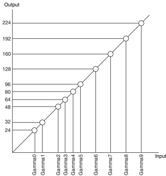
Speaker Setup
Some of the settings in this section are set automatically by Audyssey MultEQ® XT Room Correction and Speaker Setup (see page 56).
Here you can check the settings made by Audyssey MultEQ® XT Room Correction and Speaker Setup, or set them manually, which is useful if you change one of the connected speakers after using Audyssey MultEQ® XT Room Correction and Speaker Setup.
Note:
The Speaker Setup cannot be carried out while headphones are connected to the AV controller.
| 1 | Press the [RECEIVER] button followed by the [SETUP] button. |
| The main menu appears onscreen. | |
| If the main menu doesn’t appear, make sure the appropriate external input is selected on your TV. |
| 2 | Use the Up and Down [▲]/[▼] buttons to select “2. Speaker Setup”, and then press [ENTER]. |
| 3 | Use the Up and Down [▲]/[▼] buttons to select the submenu, and then press [ENTER]. |
| 4 | Use the Up and Down [▲]/[▼] buttons to select setting, and then use the Left and Right [▲]/[▼] buttons to set them. |
| 5 | When you've finished, press the [SETUP] button. |
| The setup menu closes. |
Note:
This procedure can also be performed on the AV controller by using its [SETUP] button, arrow buttons, and [ENTER] button.
Speaker Settings
See "Speaker Settings" on page 53.
Speaker Configuration
With these settings, you can specify which speakers are connected and a crossover frequency for each speaker. Specify "Full Band" for speakers that can output low frequency bass sounds adequately, for example, speakers with a good sized woofer. For smaller speakers, specify a crossover frequency. Sounds below the crossover frequency will be output by the subwoofer instead of the speaker. Refer to your speaker's manuals to determine the optimum crossover frequencies.
If you set up your speakers using Audyssey MultEQ® XT Room Correction and Speaker Setup, please make sure manually that any THX speakers are set to "80Hz(THX)" crossover.
| Subwoofer | 1ch: Audio signal is outputted from SW1 jack only. 2ch: Audio signal is outputted from SW1 and SW2 jacks (default). No: Select if no subwoofer is connected. |
| Front*1 | Full Band, 40Hz, 50Hz, 60Hz, 70Hz, 80Hz(THX) (default), 90Hz, 100Hz, 120Hz, 150Hz, 200Hz |
| Center*2 | Full Band, 40Hz, 50Hz, 60Hz, 70Hz, 80Hz(THX), 90Hz, 100Hz, 120Hz, 150Hz, 200Hz |
| Surround*2 | None: Select if no speaker is connected. |
| Front Wide*2*3 | |
| Front High*2*3 | |
| Surr Back*3*4*5 | |
| Surr Back Ch*6 | 1ch: Select if only one surround back L speaker is connected. 2ch: Select if two (left and right) surround back speakers are connected (default). |
LPF of LFE (Low-Pass Filter for the LFE Channel)
80Hz(THX)(default), 90Hz, 100Hz, 120Hz
This setting is not set automatically by Audyssey MultEQ® XT Room Correction and Speaker Setup (see page 56).
With this setting, you can specify the cutoff frequency of the LFE channel's low-pass filter (LPF), which can be used to filter out unwanted hum. The LPF only applies to sources that use the LFE channel.
- If you're using THX-certified speakers, select "80Hz(THX)".
DoubleBass*7
On: Double Bass function on (default).
Off(THX): Double Bass function off.
This setting is not set automatically by Audyssey MultEQ® XT Room Correction and Speaker Setup (see page 56).
With the Double Bass function, you can boost bass output by feeding bass sounds from the front left and right, center channels to the subwoofer.
- If you're using THX-certified speakers, select "Off(THX)".
Notes:
The "Front Wide" and "Front High" settings are cannot be set at the same time.
1 If the "Subwoofer" setting is set to "No", the "Front" setting is fixed at "Full Band".
2 If the "Front" setting is set to anything other than "Full Band", "Full Band" cannot be selected here.
3 If the "Surround" setting is set to "None", this setting cannot be selected.
4 If the "Surround" setting is set to anything other than "Full Band", "Full Band" cannot be selected here.
5 If the "Speakers Type(Front)" setting is set to "Bi-Amp" (page 53), this setting cannot be selected.
6 If the "Surr Back" setting is set to "None", this setting cannot be selected.
*7 This function can be set only if the "Subwoofer" setting is set to "1ch" or "2ch", and the "Front" setting is set to "Full Band".
Speaker Distance
This setting is set automatically by Audyssey MultEQ® XT Room Correction and Speaker Setup (see page 56). Here you can specify the distance from each speaker to the listening position so that the sound from each speaker arrives at the listener's ears as the sound designer intended.
Unit
feet: Distances can be set in feet. Range: 0.5 to 30 feet in 0.5-foot steps.
(North American models: default)
meters: Distances can be set in meters. Range: 0.15 to 9 meters in 0.15-meter steps.
(European and Asian models: default)
Left, Front Wide Left, Front High Left, Center, Front High Right, Front Wide Right, Right, Surr Right, Surr Back Right, Surr Back Left, Surr Left, Subwoofer 1, Subwoofer 2^*1
Specify the distance from the each speaker to your listening position.
Note:
You cannot select speakers that you set to "No" or "None" in the "Speaker Configuration" (page 90).
*1 If the "Subwoofer" setting is set to "lch", this setting cannot be selected.
Level Calibration
Level Calibration can be set automatically by Audyssey MultEQ® XT Room Correction and Speaker Setup (see page 56).
If you prefer, you can adjust the level of each speaker with the built-in test tone so that the volume of each speaker is the same at the listening position.
Left, Front Wide Left, Front High Left, Center, Front High Right, Front Wide Right, Right, Surr Right, Surr Back Right, Surr Back Left, Surr Left, Subwoofer 1, Subwoofer 2^*1
The levels can be adjusted from -12.0 to +12.0dB in 0.5dB steps (-15.0 to +12.0dB for the subwoofer).
Notes:
- The speakers cannot be calibrated while the output of the AV controller is muted.
- The test tone is output at the standard level for THX, which is 0 dB (absolute volume setting 82). If you normally listen at volume settings below this, be careful because the test tone will be much louder.
- You cannot get the test tone from speakers that you set to "No" or "None" in the "Speaker Configuration" (page 90).
*1 If the "Subwoofer" setting is set to "1ch", this setting cannot be selected.
Tip:
If you're using a handheld sound level meter, adjust the level of each speaker so that it reads 75 dB SPL at the listening position, measured with C-weighting and slow reading.
Equalizer Settings
This setting is set automatically by Audyssey MultEQ® XT Room Correction and Speaker Setup (see page 56).
With the Equalizer settings, you can adjust the tone of speakers individually with a 7-band equalizer. The volume of each speaker can be set on this page.
Notes:
- You can select: "63Hz", "160Hz", "400Hz", "1000Hz", "2500Hz", "6300Hz", or "16000Hz". And for the subwoofer, "25Hz", "40Hz", "63Hz", "100Hz", or "160Hz".
- While the Direct or Pure Audio listening mode is selected, the equalizer settings have no effect.
Equalizer
Manual: You can adjust the equalizer for each speaker manually. If you selected "Manual", continue with this procedure.
1 Press the Down [▼] button to select "Channel", and then use the Left and Right [▲]/[▶] buttons to select a speaker.
2 Use the Up and Down [] / [] buttons to select a frequency, and then use the Left and Right [] / [] buttons to adjust the level at that frequency.
The volume at each frequency can be adjusted from -6 to +6 dB in 1 dB steps.
Tip:
Low frequencies (e.g., 63Hz ) affect bass sounds; high frequencies (e.g., 16000Hz ) affect treble sounds.
3 Use the Up [▲] button to select "Channel", and then use the Left and Right []/[] buttons to select another speaker.
Repeat steps 1 and 2 for each speaker.
You cannot select speakers that you set to "No" or "None" in the "Speaker Configuration" (see page 90).
Audyssey: The tone for each speaker is set automatically by Audyssey MultEQ® XT Room Correction and Speaker Setup. Be sure to select this setting after having performed Room Correction and Speaker Setup. "Audyssey" is automatically selected when "Dynamic EQ" and "Dynamic Volume" are set to "On" (see page 96). When "Audyssey" is selected, "Dolby Volume" becomes "Off" automatically (see page 113).
Off: Tone off, response flat (default).
THX Audio Setup
This setting is not set automatically by Audyssey MultEQ® XT Room Correction and Speaker Setup (see page 56). With the "SurrBack Sp Spacing" setting, you can specify the distance between your surround back speakers.
If you're using a THX-certified subwoofer, set the "THX Ultra2/Select2 Subwoofer" setting to "Yes". You can then apply THX's Boundary Gain Compensation (BGC) to compensate the perceived exaggeration of low frequencies for listeners sitting very close to a room boundary (i.e., wall).
You can also set the THX Loudness Plus. When the "Loudness Plus" is set to "On", it is possible to enjoy even subtle nuances of audio expression at low volume.
This result is only available when the THX listening mode is selected.
SurrBack Sp Spacing
<1ft (<0.3m):
Select this if your surround back speakers are between 0 and 1 foot (0 - 30cm) apart.
1 ft - 4 ft (0.3 m - 1.2 m):
Select this if your surround back speakers are between 1 and 4 feet (0.3 - 1.2m) apart.
4ft (>1.2m) (default):
Select this if your surround back speakers are more than 4 feet (1.2m) apart.
Note:
Cannot be set if "Surr Back Ch" is set to "1ch" (page 90) or "Surr Back" is set to "None" (page 90).
THX Ultra2/Select2 Subwoofer
No: Select this if you do not have a THX-certified subwoofer.
Yes: Select this if you have a THX-certified subwoofer.
Note:
If the "Subwoofer" setting is set to "No", this setting cannot be selected (page 90).
BGC
Off: Select this to turn off BGC.
On: Select this to turn on BGC.
Note:
This setting is only available if "THX Ultra2/Select2 Subwoofer" is set to "Yes".
Loudness Plus
Off: Select this to turn off Loudness Plus.
On: Select this to turn on Loudness Plus (default).
Preserve THX Settings
Yes: Audyssey Dynamic EQTM/Audyssey Dynamic VolumeTM will not be active in THX listening mode.
No: Audyssey Dynamic EQ/Audyssey Dynamic Volume will be active in THX listening mode depending on the setting.
Note:
This setting is fixed at "Yes" if "Loudness Plus" is set to "On".
THX Loudness Plus
THX Loudness Plus is a new volume control technology featured in THX Ultra2 Plus™ and THX Select2 Plus™ Certified receivers. With THX Loudness Plus, home theater audiences can now experience the rich details in a surround mix at any volume level. A consequence of turning the volume below Reference Level is that certain sound elements can be lost or perceived differently by the listener. THX Loudness Plus compensates for the tonal and spatial shifts that occur when the volume is reduced by intelligently adjusting ambient surround channel levels and frequency response. This enables users experience the true impact of soundtracks regardless of the volume setting. THX Loudness Plus is automatically applied when listening in any THX listening mode. The new THX Cinema, THX Music, and THX Games modes are tailored to apply the proper THX Loudness Plus settings for each type of content.
Audio Adjust
With the Audio Adjust functions and settings, you can adjust the sound and listening modes as you like.
| 1 | Press the [RECEIVER] button followed by the [SETUP] button. The main menu appears onscreen. If the main menu doesn’t appear, make sure the appropriate external input is selected on your TV. |
| 2 | Use the Up and Down [▲]/[▼] buttons to select “3. Audio Adjust”, and then press [ENTER]. |
| 3 | Use the Up and Down [▲]/[▼] buttons to select the submenu, and then press [ENTER]. |
| 4 | Use the Up and Down [▲]/[▼] buttons to select setting, and then use the Left and Right [▲]/[▼] buttons to set them. |
| 5 | When you've finished, press the [SETUP] button. The setup menu closes. |
Note: This procedure can also be performed on the AV controller by using its [SETUP] button, arrow buttons, and [ENTER] button.
Multiplex/Mono
Multiplex
Input Channel
Main: The main channel is output (default).
Sub: The sub channel is output.
Main/Sub: Both the main and sub channels are output.
This setting determines which channel of a stereo multiplex source is output. Use it to select audio channels or languages with multiplex sources, multilingual TV broadcasts, and so on.
Mono
Input Channel
Left + Right: Both the left and right channels are output (default).
Left: Only the left channel is output.
Right: Only the right channel is output.
This setting specifies the channel to be used for playing any 2-channel digital source such as Dolby Digital, or 2-channel analog/PCM source in the Mono listening mode.
Output Speaker
Center: Mono audio is output by the center speaker (default).
Left / Right: Mono audio is output by the front left and right speakers.
This setting determines which speakers output mono audio when the Mono listening mode is selected.
Note:
If the "Center" setting is set to "None" (page 90), this setting is fixed at "Left / Right".
Dolby
PLlIx Music (2ch Input)
These settings apply to only 2-channel stereo sources.
If you're not using any surround back speakers, these settings apply to Dolby Pro Logic II, instead of Dolby Pro Logic IIx.
Panorama
On: Panorama function on.
Off: Panorama function off (default).
With this setting, you can broaden the width of the front stereo image when using the Dolby Pro Logic IIx Music listening mode.
Dimension
-3 to +3 (default: 0)
With this setting, you can move the sound field forward or backward when using the Dolby Pro Logic IIx Music listening mode. Higher settings move the sound field backward. Lower settings move it forward.
If the stereo image feels too wide, or there's too much surround sound, move the sound field forward to improve the balance. Conversely, if the stereo image feels like it's in mono, or there's not enough surround sound, move it backward.
Center Width 0 to 7 (default: 3)
With this setting, you can adjust the width of the sound from the center speaker when using the Dolby Pro Logic IIx Music listening mode. Normally, if you're using a center speaker, the center channel sound is output by only the center speaker. (If you're not using a center speaker, the center channel sound will be distributed to the front left and right speakers to create a phantom center). This setting controls the front left, right, and center mix, allowing you to adjust the weight of the center channel sound.
PLlIz Height Gain Low: Low PLIIz Height Gain becomes active.
Mid: Medium PLIIz Height Gain becomes active (default).
High: High PLIIz Height Gain becomes active.
The Height Gain Control in Dolby Pro Logic IIz enables the listener to select how much gain is applied to the front high speakers. There are three settings, "Low", "Mid" and "High", and the front high speakers are accentuated in that order. While "Mid" is the default listening setting, the listener may adjust the Height Gain Control to their personal preference.
Dolby EX Auto: If the source signal contains a Dolby EX flag, the Dolby EX or THX Surround EX listening mode is used.
Manual: You can select any available listening mode (default).
This setting determines how Dolby EX encoded signals are handled. This setting is unavailable if no surround back speaker is connected. This setting is effective with Dolby Digital, Dolby Digital Plus and Dolby TrueHD only.
Note:
If the "Front High" and "Front Wide" settings are set to other than "None" (page 90), this setting is fixed at "Manual".
Dolby Volume Off: Dolby Volume off (default).
Low: Low Compression Mode becomes active.
Mid: Medium Compression Mode becomes active.
High: High Compression Mode becomes active. This setting affects volume the most, causing all sounds to be of equal loudness.
Dolby Volume is an intelligent volume control system that resolves and improves audio frequency response and volume inconsistencies in playback applications.
Notes:
- When the "Dolby Volume" is set to effective, "Equalizer" setting is set to "Off" or "Manual", and "Dynamic EQ" is set to "Off".
- When the "Dolby Volume" is set to effective, the Late Night function cannot be set.
Half Mode Off: Half Mode off.
On: Half Mode on (default).
The Half Mode parameter turns Dolby Volume Half Mode processing ON and OFF.
In OFF mode, Dolby Volume applies a bass and treble attenuation to the audio when the system gain exceeds reference level. This enables a more perceptually flat listening experience as human ears are more sensitive to bass and treble at higher levels. Some listeners however, prefer to have more bass and treble performance at higher gain levels.
Notes:
- If the "Dolby Volume" setting is set to "Off", this setting cannot be selected.
- During Half Mode ON playback, Dolby Volume does not apply a bass and treble attenuation when the system volume exceeds reference level thereby boosting perception of high and low frequencies.
DTS
Neo:6 Music
Center Image 0 to 5 (default: 2)
The DTS Neo:6 Music listening mode creates 6-channel surround sound from 2-channel stereo sources. With this setting, you can specify by how much the front left and right channel output is attenuated in order to create the center channel.
Setting a value "0" in the middle is set to hear a sound. Sound is spread in left and right (the outside) so that the set value is made big. Please adjust by liking.
Audyssey
For "Dynamic EQ", "Reference Level" and "Dynamic Volume", you cannot change the settings before completing Audyssey MultEQ® XT Room Correction and Speaker Setup.
Dynamic EQ
Off: Audyssey Dynamic EQTM off (default).
On: Audyssey Dynamic EQTM on.
With Audyssey Dynamic EQ™, you can enjoy great sound even when listening at low volume levels.
Audyssey Dynamic EQ solves the problem of deteriorating sound quality as volume is decreased by taking into account human perception and room acoustics. It does so by selecting the correct frequency response and surround volume levels moment-by-moment so that the content sounds the way it was created at any volume level—not just at reference level.
Reference Level
Movies are mixed in rooms calibrated for film reference. To achieve the same reference level in a home theater system each speaker level must be adjusted so that -30 dBFS band-limited (500 Hz to 2000 Hz) pink noise produces 75 dB sound pressure level at the listening position. A home theater system automatically calibrated by Audyssey MultEQ® will play at reference level when the master volume control is set to the 0 dB position. At that level you can hear the mix as the mixers heard it.
Audyssey Dynamic EQ™ is referenced to the standard film mix level. It makes adjustments to maintain the reference response and surround envelopment when the volume is turned down from 0 dB. However, film reference level is not always used in music or other non-film content. The Dynamic EQ Reference Level Offset provides three offsets from the film level reference (5 dB, 10 dB, and 15 dB) that can be selected when the mix level of the content is not within the standard.
Dynamic EQ Reference Level Offset
0 dB: This is the default setting and should be used when listening to movies.
5 dB: Select this setting for content that has a very wide dynamic range, such as classical music.
10 dB: Select this setting for jazz or other music that has a wider dynamic range. This setting should also be selected for TV content as that is usually mixed at 10 dB below film reference.
15 dB: Select this setting for pop/rock music or other program material that is mixed at very high listening levels and has a compressed dynamic range.
Note:
If "Dynamic EQ" setting is set to "Off", this setting cannot be selected.
Dynamic Volume (see page 56)
Off: Audyssey Dynamic VolumeTM off (default).
Light: Light Compression Mode becomes active.
Medium: Medium Compression Mode becomes active.
Heavy: Heavy Compression Mode becomes active. This setting affects volume the most, causing all sounds to be of equal loudness.
Note:
After Audyssey MultEQ® XT Room Correction and Speaker Setup is completed, even if "Equalizer" setting is not set to "Audyssey", when "Dynamic EQ" setting is set to "On", "Equalizer" settings is set to "Audyssey". When "Dynamic Volume" is set to effective, "Equalizer" setting is set to "Audyssey" and "Dynamic EQ" is set to "On". When "Dynamic EQ" is set to "Off", "Dynamic Volume" becomes "Off" automatically.
Soundstage -3dB, -2dB, -1dB, Reference (default), +1dB, +2dB, +3dB
Adjusts the soundstage when using Audyssey Dynamic Surround Expansion™.
Note:
If the "Center" setting is set to "None", or both "Front High" and "Front Wide" settings are set to "None" (page 90), this setting cannot be selected.
Theater-Dimensional
Listening Angle
Wide: Select if the listening angle is greater than 30 degrees (default).
Narrow: Select if the listening angle is less than 30 degrees.
With this setting, you can optimize the Theater-Dimensional listening mode by specifying the angle of the front left and right speakers relative to the listening position.
Front left speaker
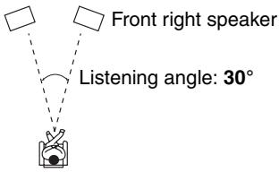
LFE Level
With these settings, you can set the level of the LFE (Low Frequency Effects) channel individually for Dolby Digital, DTS, multichannel PCM, Dolby TrueHD, DTS-HD Master Audio, and DSD sources.
If you find that low-frequency effects are too loud when using one of these sources, change the setting to -20dB or - dB.
Dolby Digital ^1 , DTS ^2,2 , Multich PCM ^3 , Dolby TrueHD ^4 , DTS-HD Master Audio ^5 , DSD ^6
The level can be set to - dB, -20 dB, -10 dB, or 0 dB (default).
Notes:
1 Sets the level of the LFE channel for Dolby Digital and Dolby Digital Plus sources.
2 Sets the level of the LFE channel for DTS and DTS-HD High Resolution sources.
3 Sets the level of the LFE channel for multichannel PCM sources. (Multichannel PCM is input via HDMI.)
4 Sets the level of the LFE channel for Dolby TrueHD sources.
5 Sets the level of the LFE channel for DTS-HD Master Audio sources.
6 Sets the level of the LFE channel for DSD (Super Audio CD) sources.
Direct
Analog
Subwoofer
This setting determines whether or not analog audio signals (bass signals) are output from front speakers when the Pure Audio or Direct listening mode is selected.
Off: Analog audio signals (bass signals) are not output (default).
On: Analog audio signals (bass signals) are output.
DSD
DAC Direct
This setting determines whether or not DSD (Super Audio CD) audio signals are passed through the DSP processing when the Pure Audio or Direct listening mode is selected.
Off: DSD signals are processed by the DSP (default).
On: DSD signals are not processed by the DSP.
Note:
Once you have selected "Yes", only DAC Direct will be available for selection. "DSD Direct" will appear on the display.
Source Setup
This section explains items on the "Source Setup" menu. Items can be set individually for each input selector.
1 Press the input selector buttons to select an input source.
2 Press the [RECEIVER] button followed by the [SETUP] button.
The main menu appears onscreen.
If the main menu doesn't appear, make sure the appropriate external input is selected on your TV.
3 Use the Up and Down [ ] / [ ] buttons to select "4. Source Setup", and then press [ENTER].
The "Source Setup" menu appears. The name of the currently selected input selector is displayed.
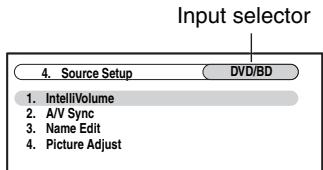
For NET/USB input source only "IntelliVolume" will be available.
4 Use the Up and Down [] / [] buttons to select an item, and then press [ENTER].
5 Use the Left and Right [] / [] buttons to change it.
The "Source Setup" menu items are explained below.
6 When you've finished, press the [SETUP] button.
The setup menu closes.
Note:
This procedure can also be performed on the AV controller by using its input selector buttons, [SETUP] button, arrow buttons, and [ENTER] button.
IntelliVolume
With IntelliVolume, you can set the input level for each input selector individually. This is useful if one of your source components is louder or quieter than the others.
If a component is noticeably louder than the others, use the Left [<] button to reduce its input level. If it's noticeably quieter, use the Right [▶] button to increase its input level.
IntelliVolume -12 dB to +12 dB (default: 0 dB)
A/V Sync
When using your DVD player's progressive scanning function, you may find that the picture and sound are out of sync. With the A/V Sync setting, you can correct this by applying a delay to the audio signal.
To view the TV picture while setting the delay, press [ENTER]. To return to the previous screen, press the [RETURN] button.
A/V Sync 0 ms to 250 ms in 5 ms steps (default: 0 ms)
If HDMI Lip Sync is enabled (see page 108), and your TV or display supports HDMI Lip Sync, the displayed delay time will be the summation of the A/V Sync delay time and the HDMI Lip Sync delay time. The HDMI Lip Sync delay time is displayed underneath in parentheses.
Note:
A/V Sync is disabled when the Pure Audio listening mode is selected, or when the Direct listening mode is used with an analog input source.
Name Edit
You can enter a custom name for each individual input selector (excluding TUNER) and radio preset for easy identification. When entered, the custom name will appear on the display.
Notes:
- To name a radio preset, use the [TUNER] button to select AM or FM, and then select the preset (see page 68).
- (North American models) You cannot enter a custom name for SIRIUS radio presets.
To restore a custom name to the default, erase the custom name by entering an empty white space for each letter.
1 Use the arrow [] / [] / [] / [] buttons to select a character, and then press [ENTER].
Repeat this step to enter up to 10 characters.
2 When you've finished, to store a name, be sure to use the arrow [] / [] / [] / [] buttons to select "OK", and then press [ENTER].
Otherwise it will not be saved.
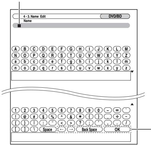
Name input area
(Left) (Right):
Selected when the cursor is moved within the Name input area.
Back Space:
"Back Space" deletes one character to the left of the cursor.
OK:
Selects when the entry is complete.
To correct a character:
- Use the arrow [] / [] / [] / [] buttons to select “ ”(Left) or “ ”(Right) and then press [ENTER].
- Press [ENTER] several times to select the incorrect character (The cursor moves one letter each time [ENTER] is pressed).
- Use the arrow [] / [] / [] / [] buttons to select the correct character, and then press [ENTER].
Picture Adjust
Using Picture Adjust, you can adjust the picture quality and reduce any noise appearing on the screen.
To view the TV picture while setting, press [ENTER]. To return to the previous screen, press the [RETURN] button. "Picture Adjust" is not operable when the input selector is set to "NET/USB".
Tip:
The "Picture Adjust" menus (excluding "Red Brightness" to "Blue Contrast") can also be set using the [VIDEO] button on the remote controller.
- Press the [RECEIVER] button, followed by the [VIDEO] button.
- Use the Up and Down [] / [] buttons to select item, and then use the Left and Right [] / [] buttons to change the setting.
Game Mode
Off: Game Mode off (default).
On: Game Mode on.
If video signal delay occurs during playback on a video component (i.e. game console), select the corresponding input source and set the "Game Mode" setting to "On". The delay will decrease but in return the picture quality will become poor.
Zoom Mode
This setting determines the aspect ratio.
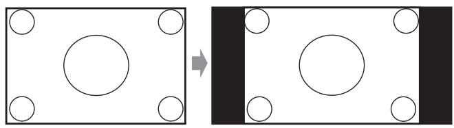
Normal:
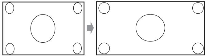
Full: (default)
Zoom:

Wide Zoom:
| ISF Mode | Custom: User setting (All items can be freely set.) |
| Day: Setting when a room is bright. | |
| Night: Setting when a room is dark. | |
| The receiver has been designed to incorporate setup and calibration standards established by the Imaging Science Foundation (ISF). The ISF has developed carefully crafted, industry-recognized standards for optimal video performance and has implemented a training program for technicians and installers to use these standards to obtain optimal picture quality from the receiver. Accordingly, Onkyo recommends that setup and calibration be performed by an ISF Certified installation technician. | |
| Picture Mode*1*2 | Auto: The type of content is detected automatically and processed accordingly (default). |
| Video: Select when playing a DVD-Video disc whose content originates from video. | |
| Film: Select when playing a DVD-Video disc whose content originates from film. | |
| DVD-Video disc content originates from either film (recorded at 24 frames per second) or video intended for TV (recorded at 30 frames per second). With the default Picture Mode setting of Auto, the AV controller automatically detects the type of content and processes it accordingly to achieve the best picture quality. If the AV controller detects the type of content incorrectly due to characteristics of the disc, you can select Video or Film manually. | |
| Edge Enhancement*2 | Off: Edge enhancement off (default). |
| Low: Low edge enhancement. | |
| Mid: Medium edge enhancement. | |
| High: High edge enhancement. | |
| With Edge Enhancement, you can make the picture appear sharper. | |
| Mosquito NR*1*2 | Off: Mosquito noise reduction off (default). |
| Low: Low mosquitonoise reduction. | |
| Mid: Medium mosquitonoise reduction. | |
| High: High mosquitonoise reduction. | |
| With Mosquito Noise Reduction, you can remove the shimmering or haziness that sometimes appears around objects in the picture. Mosquito noise can be an issue with overly compressed MPEG content. | |
| Random NR*1*2 | Off: Random noise reduction off (default). |
| Low: Low random noise reduction. | |
| Mid: Medium random noise reduction. | |
| High: High random noise reduction. | |
| With Random Noise Reduction, you can remove indiscriminate picture noise, such as film grain. | |
| Block NR*1*2 | Off: Block noise reduction off (default). |
| On: Block noise reduction on. | |
| With Block Noise Reduction, you can remove the block distortion that sometimes appears in the picture. Block noise can be an issue with overly compressed MPEG content. | |
Notes:
1 When the "Game Mode" setting is set to "On", this setting cannot be selected.
2 When the "ISF Mode" setting is set to "Day" or "Night", this setting cannot be selected.
| Resolution*2 | Through: Select this to pass video through the AV controller at the same resolution and with no conversion (default). Auto: Select this to have the AV controller automatically convert video at resolutions not supported by your TV. When the “Monitor Out” is set to “Analog”, this setting will be changed to “Through”. |
| 480p (480/576p): Select this for 480p or 576p output and video conversion as necessary. 720p: Select this for 720p output and video conversion as necessary. 1080i: Select this for 1080i output and video conversion as necessary. 1080p: Select this for 1080p output and video conversion as necessary. When the “Monitor Out” is set to “Analog”, this setting will be changed to “1080i”. 1080p/24: Select this for 1080p output at 24 frames per second and video conversion as necessary. When the “Monitor Out” is set to “Analog”, this setting will be changed to “1080i”. | |
| You can specify the output resolution for the HDMI outputs and have the AV controller upconvert the picture resolution as necessary to match the resolution supported by your TV. Available only when “Source” has been selected in the “Resolution” of the “Monitor Out” setting (page 48). | |
| Brightness*2 | -50 to +50 (default: 0) |
| With this setting you can adjust the picture brightness. “-50” is the darkest. “+50” is the brightest. | |
| Contrast*2 | -50 to +50 (default: 0) |
| With this setting you can adjust contrast. “-50” is the least. “+50” is the greatest. | |
| Hue*2 | -20 to +20 (default: 0) |
| With this setting you can adjust the red/green balance. “-20” is the strongest green. “+20” is the strongest red. | |
| Saturation*2 | -50 to +50 (default: 0) |
| With this setting you can adjust saturation. “-50” is the weakest color. “+50” is the strongest color. | |
| Gamma*2 | -3 to +3 (default: 0) |
| Adjust the balance of color data signal R (red), G (green), and B (blue) of incoming picture. | |
Red Brightness*2 -50 to +50 (default: 0)
With this setting you can adjust the picture red brightness. “-50” is the darkest. “+50” is the brightest.
Red Contrast*2 -50 to +50 (default: 0)
With this setting you can adjust red contrast. “-50” is the least. “+50” is the greatest.
Green Brightness*2 -50 to +50 (default: 0)
With this setting you can adjust the picture green brightness. “-50” is the darkest. “+50” is the brightest.
Green Contrast*2 -50 to +50 (default: 0)
With this setting you can adjust green contrast. “-50” is the least. “+50” is the greatest.
Blue Brightness*2 -50 to +50 (default: 0)
With this setting you can adjust the picture blue brightness. “-50” is the darkest. “+50” is the brightest.
Blue Contrast*2 -50 to +50 (default: 0)
With this setting you can adjust blue contrast. “-50” is the least. “+50” is the greatest.
Note:
*2 When the "ISF Mode" setting is set to "Day" or "Night", this setting cannot be selected.
Assigning Listening Modes to Input Sources
You can assign a default listening mode to each input source that will be selected automatically when you select each input source. For example, you can set the default listening mode to be used with Dolby Digital input signals. You can select other listening modes during playback, but the mode specified here will be resumed once the AV controller has been set to Standby.
1 Press the [RECEIVER] button followed by the [SETUP] button.
The main menu appears onscreen.
If the main menu doesn't appear, make sure the appropriate external input is selected on your TV.
2 Use the Up and Down [ ] / [ ] buttons to select "5. Listening Mode Preset", and then press [ENTER].
The "Listening Mode Preset" menu appears.
3 Use the Up and Down [] / [] buttons to select the input source that you want to set, and then press [ENTER].
The signal format selection menu appears.
![ONKYO PR-SC5507 - Use the Up and Down [] / [] buttons to select the input source that you want to set, and then press [ENTER]. - 1](/content/2025/01/151815/images/0c658084a4615b15c0b7188ca7da5378432b86df83ed59712241695ed0b5d2ae.jpg)
For TUNER input source only "Analog" will be available. For NET/USB input source only "Digital" will be available.
4 Use the Up and Down [▲]/[▼] buttons to select the signal format that you want to set, and then use the Left and Right [▲]/[▼] buttons to select a listening mode.
5 When you've finished, press the [SETUP] button.
The setup menu closes.
Notes:
- If you connect an input component (such as UP-A1 Dock that seated iPod) to the UNIVERSAL PORT jack, you can assign only "Analog" to PORT input source.
- This procedure can also be performed on the AV controller by using its [SETUP] button, arrow buttons, and [ENTER] button.
Listening Mode Preset
Analog/PCM: With this setting, you can specify the listening mode to be used when an analog (CD, TV, LD, VHS, MD, turntable, radio, cassette, cable, satellite, etc.) or PCM digital (CD, DVD, etc.) audio signal is played.
Dolby Digital: With this setting, you can specify the listening mode to be used when a Dolby Digital or Dolby Digital Plus format digital audio signal is played (DVD, etc.).
DTS: With this setting, you can specify the listening mode to be used when a DTS or DTS-HD High Resolution format digital audio signal is played (DVD, LD, CD, etc.).104
D.F. 2ch: Specifies the default listening mode for 2-channel (2/0) stereo sources in a digital format, such as Dolby Digital or DTS.
D.F. Mono: With this setting, you can specify the listening mode to be used when a mono digital audio signal is played (DVD, etc.).
Multich PCM: Specifies the default listening mode for multichannel PCM sources input via a HDMI IN, such as DVD-Audio.
Dolby TrueHD: Specifies the default listening mode for Dolby TrueHD sources, such as Blu-ray or HD DVD (input via HDMI).
DTS-HD Master Audio: Specifies the default listening mode for DTS-HD Master Audio sources, such as Bluray or HD DVD (input via HDMI).
DSD: Specifies the default listening mode for DSD multichannel sources, such as Super Audio CD.
Only listening modes that can be used with each input signal format can be selected (see pages 76 to 82).
The Last Valid option means that the listening mode selected last will be used.
Miscellaneous (Volume/OSD) Setup
This section explains the items on the "Miscellaneous" menu.
Press the [RECEIVER] button followed by the [SETUP] button.
The main menu appears onscreen.
If the main menu doesn't appear, make sure the appropriate external input is selected on your TV.
2 Use the Up and Down [] / [] buttons to select "6. Miscellaneous", and then press [ENTER].
The "Miscellaneous" menu appears.
6. Miscellaneous
- Volume Setup
- OSD Setup
- 12V Trigger A Setup
- 12V Trigger B Setup
- 12V Trigger C Setup
- 12V Trigger C Setup
3 Use the Up and Down [] / [] buttons to select an item, and then press [ENTER].
The screen for that item appears.
4 Use the Up and Down [] / [] buttons to select an item, and use the Left and Right [] / [] buttons to change it.
The items are explained below.
5 When you've finished, press the [SETUP] button.
The setup menu closes.
Note:
This procedure can also be performed on the AV controller by using its [SETUP] button, arrow buttons, and [ENTER] button.
Volume Setup
| Volume Display | Absolute: Display range is “Min”, 0.5 through 99.5, “Max”. Relative: Display range is -∞ dB, -81.5 dB through +18.0 dB. |
| With this setting, you can choose how the volume level is displayed. | |
| The absolute value 82 is equivalent to the relative value 0 dB. | |
| Muting Level | -∞ dB (fully muted), -50 dB to -10 dB in 10 dB steps |
| This setting determines how much the output is muted when the muted function is used (page 64). | |
| Maximum Volume | Off, 50 to 99 (Absolute display) Off, -32 dB to +17 dB (Relative display) |
| With this setting, you can limit the maximum volume. | |
| To disable this setting, select “Off”. | |
| Power On Volume | Last, Min, 1 to 99 or Max (Absolute display) Last, -∞ dB, -81 dB to +18 dB (Relative display) |
| With this preference, you can specify the volume setting to be used each time the AV controller is turned on. | |
| To use the same volume level that was used when the AV controller was turned off, select “Last”. | |
| The “Power On Volume” cannot be set higher than the “Maximum Volume” setting. | |
| Headphone Level | -12 dB to +12 dB |
With this preference, you can specify the headphone volume relative to the main volume. This is useful if there's a volume difference between your speakers and your headphones.
OSD Setup
| Immediate Display | On: Displayed (default). Off: Not displayed. |
| This preference determines whether operation details are displayed onscreen when an AV controller function is adjusted. Even when “On” is selected, operation details may not be output if the input source is connected to an HDMI IN. | |
| Display Position | Bottom: Bottom of the screen (default). Top: Top of the screen. |
| This preference determines where on the screen operation details are displayed. | |
| TV Format (European and Asian models) | |
| See “TV Format Setup (European and Asian models)” on page 54. | |
| Language | |
| See “Selecting the Language used for the onscreen setup menus” on page 45. | |
12V Trigger A/B/C Setup
See "Using the 12V Triggers" on page 131.
Hardware Setup
This section explains items on the "Hardware Setup" menu.
Press the [RECEIVER] button followed by the [SETUP] button.
The main menu appears onscreen.
If the main menu doesn't appear, make sure the appropriate external input is selected on your TV.
2 Use the Up and Down [] / [] buttons to select "7. Hardware Setup", and then press [ENTER].
The "Hardware Setup" menu appears.
| 7. Hardware Setup |
| 1. Remote ID |
| 2. Multi Zone |
| 3. Tuner |
| 4. HDMI |
| 5. Network |
| 6. Firmware Update |
3 Use the Up and Down [▲]/[▼] buttons to select an item, and then press [ENTER].
The screen for that item appears.
4 Use the Up and Down [] / [] buttons to select an item, and use the Left and Right [] / [] buttons to change it.
The items are explained below.
5 When you've finished, press the [SETUP] button.
The setup menu closes.
Note:
This procedure can also be performed on the AV controller by using its [SETUP] button, arrow buttons, and [ENTER] button.
Remote ID
Remote ID 1,2,3
When several Onkyo components are used in the same room, their remote ID codes may overlap. To differentiate the AV controller from the other components, you can change its remote ID from 1, the default, to 2 or 3.
Changing the Remote Controller's ID
1 While holding down the [RECEIVER] button, press and hold down the [SETUP] button until the RECEIVER button lights up (about 3 seconds).
2 Use the number buttons to enter ID 1, 2, or 3. The RECEIVER button flashes twice.
Note:
If you do change the AV controller's remote ID, be sure to change the remote controller to the same ID, otherwise, you won't be able to control it with the remote controller.
Multi Zone
See "Setting the Multi Zone" on page 128.
Tuner
FM/AM Frequency Step (North American models)
AM Frequency Step (European and Asian models)
See "FM/AM Frequency Step Setup" on page 54.
SAT Radio Mode (North American models)
If you connect a SIRIUS Satellite Radio antenna to the AV controller (sold separately), set this setting to "SIRIUS". See the separate Satellite Radio Guide for more information.
Antenna Aiming (North American models)
The ID of the Sirius Connect Home Tuner is displayed here. You must sign up to obtain a SIRIUS ID. See the separate Satellite Radio Guide for more information.
SIRIUS Parental Lock (North American models)
This item is for use with SIRIUS Satellite Radio. It's not available if "SAT Radio Mode" is set to "None". See the separate Satellite Radio Guide for more information.
HDMI
Audio TV Out
Off: HDMI audio is not output to TV (default).
On: HDMI audio is output to TV and the sound will be heard from the TV speakers.
This preference determines whether audio received at the HDMI input is output from the HDMI outputs. You may want to turn this preference on if your TV is connected to the HDMI output and you want to listen to the audio from a component that's connected to an HDMI input, through your TV's speakers. Normally, this should be set to "Off".
Notes:
- If "On" is selected and the signal can be output by the TV, the AV controller will output no sound through its speakers.
- If "On" is selected, "TV Speaker On" appears on the Display by pressing the [DISPLAY] button.
- When "TV Control" is set to "On", this setting is fixed at "Auto".
- With some TVs and input signals, no sound may be output even when this setting is set to "On". When you try to get audio from your TV, signals from the source component may be converted to the format supported by your TV.
- When the "Audio TV Out" setting is set to "On" or "TV Control" is set to "On" to hear from speakers of R1HD-compatible TV (page 27), by controlling the AV controller's volume, the AV controller's speakers will produce sound while the TV's speakers are muted. If your TV is not compatible with R1HD, the volume level will not change. To stop the AV controller's speakers producing sound, change the settings, change your TV's settings, or turn down the AV controller's volume.
- When the "Audio TV Out" setting is set to "On", the remote controller's [AUDIO] button is disabled.
- If the "Monitor Out" setting is set to "Both (Main)" or "Both (Sub)" (page 47) and if your TV connected to a priority output cannot output the audio, the sound will be heard from AV controller's speakers.
Lip Sync
Disable: HDMI Lip Sync disabled (default).
Enable: HDMI Lip Sync enabled.
The AV controller can be set to automatically correct any delay between the video and the audio, based on the data from the connected monitor.
Notes:
- This function works only if your HDMI-compatible TV supports HDMI Lip Sync.
- You can check the amount of delay being applied by the HDMI Lip Sync function on the A/V Sync screen (page 98).
- If the "Monitor Out" setting is set to "HDMI Main", "Both (Main)" or "Both" (page 47), the delay will be corrected in accordance with the monitor connected to HDMI OUT MAIN. On the other hand, if "HDMI Sub" or "Both (Sub)" is selected, the delay will be corrected in accordance with the monitor connected to HDMI OUT SUB.
x.v.Color
Disable: "x.v.Color" disabled (default).
Enable: "x.v.Color" enabled.
If your HDMI source and HDMI-compatible TV both support the "x.v.Color", you can enable "x.v.Color" on the AV controller with this setting.
Notes:
- If the color is unnatural when "x.v.Color" is set to "Enable", change the setting to "Disable".
- Refer to the connected component's instruction manual for details.
- If the "Monitor Out" setting is set to "Both (Main)" or "Both (Sub)" (page 47) and if your TV connected to a priority output does not support x.v.Color, output will be without x.v.Color control.
HDMI Control (RIHD)
On: R1HD enabled.
Off: RHD disabled (default).
This function allows RHD-compatible components connected via HDMI to be controlled with the AV controller.
Notes:
- RiHD, which stands for Remote Interactive over HDMI, is the name of the system control function found on Onkyo components. The AV controller can be used with CEC (Consumer Electronics Control), which allows system control over HDMI and is part of the HDMI standard. CEC provides interoperability between various components, however, operation with components other than RiHD -compatible components cannot be guaranteed.
When set to "On" and close the menu, the name of connected RIHD-compatible components and "RIHD On" are displayed on the AV controller.
"Search..." "(name)" "RIHD On"
When the AV controller cannot receive the name of the component, it is displayed as "Player*" or
"Recorder*, etc ("*" means the number of two or more component).
When set to "Off" and close the menu, "RIHD Off" are displayed on the AV controller.
"Disconnect" "RIHD Off"
- Set it to "Off" when a connected piece of equipment is not compatible or it is unclear whether the equipment is compatible or not.
- Set it to "Off" if the operation is not successful.
- Refer to the connected component's instruction manual for details.
- The R1HD control does not support HDMI OUT SUB. Use HDMI OUT MAIN instead.
Power Control
On: Power Control enabled.
Off: Power Control disabled.
To link the power functions of R1HD-compatible components connected via HDMI, select "On".
This setting is set to "On" automatically when the above "HDMI Control (RIHD)" is set to "On" for the first time.
Notes:
- The "Power Control" setting can be set only when the above "HDMI Control (RIHD)" setting is set to "On".
- HDMI power control only works with R1HD-compatible components that support it and may not work properly with some components due to their settings or compatibility.
- When set to "On", the power consumption on standby mode increases.
- When set to "On", regardless of whether the AV controller is On or on Standby, both audio and video received by an HDMI input will be output from the HDMI output for playback on the TV or other component that's connected to the HDMI output.
Refer to the connected component's instruction manual for details.
TV Control
On: TV Control enabled.
Off: TV Control disabled.
Set to "On" when you want to control the AV controller from an RHD-compatible TV that is connected to HDMI.
Notes:
- Do not assign the component connected with the HDMI input to the TV/TAPE selector when you set "TV Control" setting to "On". Otherwise, appropriate CEC (Consumer Electronics Control) operation is not guaranteed.
- Set to "Off" when the TV is not compatible or when it is unclear whether the TV is compatible or not.
- The "TV Control" setting can be set only when the above "HDMI Control (RIHD)" and "Power Control" settings are both set to "On".
Refer to the connected component's instruction manual for details.
Note:
After changing the settings of the "HDMI Control (RIHD)", "Power Control", or "TV Control", set all connected pieces of equipment to Standby and then turn them on again. Refer to the User's Manuals for all connected pieces of equipment.
Network
See "Network Settings" on page 121.
Firmware Update
Notes:
- Perform the firmware update only when an announcement is posted on the Onkyo Web site.
- It takes about 60 minutes to complete the firmware update.
- When updating a firmware from a USB mass storage device, the AV controller searches the device which is connected earlier during power on. If two devices have been connected at the time of power on, the AV controller will search the device on the front panel.
| Version The current version of the firmware is displayed. The version is made up of the versions of the AV controller and Onkyo dock (if connected). | |
| Receiver | via NET: You can update the firmware via Internet. Check the network connection before update. via USB: You can update the firmware from a USB mass storage device. |
| You can update the AV controller's firmware. Do not shutdown the power of the AV controller while update. | |
| Universal Port | via NET: You can update the firmware via Internet. Check the network connection before update. via USB: You can update the firmware from a USB mass storage device. |
| You can update the Onkyo dock's firmware. Do not shutdown the power of the AV controller while update. | |
| Note: This update shall not be performed when no dock is connected to UNIVERSAL PORT jack. | |
Lock Setup
With this preference, you can protect your settings by locking the setup menus.
Press the [RECEIVER] button followed by the [SETUP] button.
The main menu appears onscreen.
If the main menu doesn't appear, make sure the appropriate external input is selected on your TV.
2 Use the Up and Down [ ] / [ ] buttons to select "9. Lock Setup", and then press [ENTER].
The "Lock Setup" menu appears.
![ONKYO PR-SC5507 - Use the Up and Down [ ] / [ ] buttons to select "9. Lock Setup", and then press [ENTER]. - 1](/content/2025/01/151815/images/36218a391188cc317f30b48ad0ef8a799bf5dfcc70898bbc21bf263f5e9f68a7.jpg)
3 Use the Left and Right [] / [] buttons to select:
When the setup menus are locked, you cannot change any setting.
Locked:
Setup menus locked.
Unlocked:
Setup menus not locked.
4 Press the [SETUP] button.
The setup menu closes.
Note:
This procedure can also be performed on the AV controller by using its [SETUP] button, arrow buttons, and [ENTER] button.
Digital Input Signal Formats
The digital input signal formats are available only for the input sources that you have assigned a digital input jack (see page 51).
Normally, the AV controller detects the signal format automatically. However, if you experience either of the following issues when playing PCM or DTS material, you can manually set the signal format to PCM or DTS:
- If the beginnings of tracks from a PCM source are cut off, try setting the format to PCM.
- If noise is produced when fast forwarding or reversing a DTS CD, try setting the format to DTS.
- The setting is stored individually for each input selector.
Press the [RECEIVER] button, and then press and hold [AUDIO] button for about 8 seconds.
2 While "Auto" is displayed (about 3 seconds), press the Left and Right [<]/[▶] buttons to select: PCM, DTS or Auto.
PCM:
Only 2-channel PCM format input signals will be heard. If the input signal is not PCM, the PCM indicator will flash and noise may also be produced.
DTS:
Only DTS (but not DTS-HD) format input signals will be heard. If the input signal is not DTS, the DTS indicator will flash and there will be no sound.
Auto (default):
The format is detected automatically. If no digital input signal is present, the corresponding analog input is used instead.
Using the Audio Settings
You can change various audio settings by pressing the [AUDIO] button.
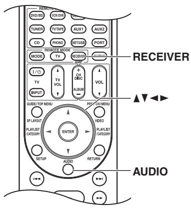
Press the [RECEIVER] button followed by the [AUDIO] button. The audio setting items appear on the display.
2 Use the Up and Down [] / [] buttons to select an item.
3 Use the Left and Right []/[] buttons to change the setting. Repeat steps 2 and 3 for the other settings.
Note: When the "Audio TV Out" setting is set to "On" (page 108), the [AUDIO] button is disabled.
Tone Control Settings
You can adjust the bass for the front, front wide, front high, center, surround, surround back and subwoofer speakers and treble for the front, front wide, front high, center, surround and surround back speakers, except when the Direct, Pure Audio or THX listening mode is selected.
Bass -10 dB to +10 dB in 2 dB steps (default: 0 dB)
You can boost or cut low-frequency sounds output by the speakers.
Treble -10 dB to +10 dB in 2 dB steps (default: 0 dB)
You can boost or cut high-frequency sounds output by the speakers.
Notes:
- To bypass the bass and treble tone circuits, select the Direct, Pure Audio or THX listening mode.
- This procedure can also be performed on the AV controller by using its [TONE], Up[ ] and Down[ ] buttons (see page 63).
Late Night Function
With the Late Night function, you can reduce the dynamic range of Dolby Digital material so that you can still hear quiet parts even when listening at low volume levels—ideal for watching movies late at night when you don't want to disturb anyone.
Late Night For Dolby Digital and Dolby Digital Plus sources, the options are:
Off: Late Night function off (default).
Low: Small reduction in dynamic range.
High: Large reduction in dynamic range.
For Dolby TrueHD sources, the options are:
Auto: The Late Night function is set to "On" or "Off" automatically (default).
Off: Late Night function off.
On: Late Night function on.
Notes:
- The effect of the Late Night function depends on the material that you are playing and the intention of the original sound designer, and with some material there will be little or no effect when you select the different options.
- The Late Night function can be used only when the input source is Dolby Digital, Dolby Digital Plus, or Dolby TrueHD.
- The Late Night function is set to "Off" when the AV controller is set to Standby. For Dolby TrueHD sources, it will be set to "Auto".
Re-EQ Function
With the Re-EQ function, you can compensate a soundtrack whose high-frequency content is too harsh, making it more suitable for home theater viewing.
Re-EQ
Off: Re-EQ Function off (default).
On: Re-EQ Function on.
This function can be used with the following listening modes: Dolby Digital, Dolby Digital Plus, Dolby TrueHD, Multichannel, DTS, DTS-HD High Resolution Audio, DTS-HD Master Audio, DTS Express, DSD, Dolby EX, Dolby Pro Logic IIz Height, Dolby PLIIx Movie, Neo:6 Cinema, 5.1-channel source + Neo:6, and Neural Surround.
Re-EQ(THX)
Off: Re-EQ (THX) Function off.
On: Re-EQ (THX) Function on (default).
This function can be used with the following listening modes: THX Cinema, THX Surround EX, and THX Ultra2 Cinema. When the AV controller is turned off, this setting is set to "On".
Audyssey Dynamic VolumeTM
Dynamic Volume See "Dynamic Volume" of "Audio Adjust" on page 96.
Note:
If you would like to use Audyssey Dynamic Volume™ in THX listening modes, set "Loudness Plus" setting to "Off" and set "Preserve THX Settings" setting to "No".
Dolby Volume
Dolby Volume
Off: Dolby Volume off (default).
Low: Low Compression Mode becomes active.
Mid: Medium Compression Mode becomes active.
High: High Compression Mode becomes active. This setting affects volume the most, causing all sounds to be of equal loudness.
Notes:
- When the "Dolby Volume" setting is set to effective, Audyssey Dynamic EQ™ and Audyssey Dynamic Volume™ will be set to "Off" from "Audyssey" and "Equalizer" setting will be set to "Off" or remain set to "Manual".
- If you would like to use Dolby Volume in THX listening modes, set "Loudness Plus" setting to "Off" and set "Preserve THX Settings" setting to "No".
Music Optimizer
The Music Optimizer function enhances the sound quality of compressed music files. Use it with music files that use "lossy" compression, such as MP3. The setting is stored individually for each input selector.
Music Optimizer
Off: Music Optimizer off (default).
On: Music Optimizer on.
Note:
The Music Optimizer function only works with PCM digital audio input signals with a sampling rate below 48kHz and analog audio input signals. The Music Optimizer is disabled when the Direct or Pure Audio listening mode is selected.
Speaker Levels
You can adjust the volume of each speaker while listening to an input source.
These temporary adjustments are cancelled when the AV controller is set to Standby. To save the setting you made here, go to "Level Calibration" on page 92 before setting the AV controller to Standby.
| Subwoofer 1 | -15.0 dB to +12.0 dB (default: 0.0 dB) |
| Subwoofer 2 | -15.0 dB to +12.0 dB (default: 0.0 dB) |
| Center | -12.0 dB to +12.0 dB (default: 0.0 dB) |
| Notes: • You cannot use this function while the AV controller is muted. • Speakers that are set to “No” or “None” in the “Speaker Configuration” cannot be adjusted (see page 90). • This function will not work when the Pure Audio or Direct listening mode is selected to play analog audio. | |
Audio Selector
You can set priorities of audio output when there are both digital and analog inputs.
Audio Selector
Auto: The AV controller gives priority to analog signals when there is no digital input (default).
Multich: The AV controller always outputs analog signals from multichannel analog input.
Balance: The AV controller always outputs analog signals from balanced input.
Analog: The AV controller always outputs analog signals.
Note:
This setting can be made only for the input source that is assigned as HDMI IN, COAXIAL IN, OPTICAL IN, multichannel input, or balanced input. If both HDMI (HDMI IN) and digital audio inputs (COAXIAL IN or OPTICAL IN) are assigned, HDMI input will be selected as a priority by setting to "Auto". To select the digital audio input, see "Digital Audio Input Setup" on page 51.
A/V Sync
See "A/V Sync" of "Source Setup" on page 98.
About NET
The AV controller is network-ready, which means you can hook it up to your home network with a standard Ethernet cable and enjoy the music files stored on your computer or media server. If your network is connected to the Internet, you can also enjoy Internet radio.
Network Requirements
■ Ethernet Network
The AV controller's Ethernet port supports 10Base-T. For best results, a 100Base-TX switched Ethernet network is recommended. Although it's possible to play music on a computer that's connected to the network wirelessly, playback may be unreliable, so wired connections are recommended.
Ethernet Router
A router manages the network, routing data and supplying IP addresses. Your router must support the following:
- NAT (Network Address Translation). NAT allows several networked computers to access the Internet simultaneously via a single Internet connection. The AV controller needs Internet access for Internet radio.
- DHCP (Dynamic Host Configuration Protocol). DHCP supplies IP addresses to network devices, allowing them to configure themselves automatically.
- A router with a 100Base-TX switch built-in is recommended.
Some routers have a modem built-in, and some ISPs require you to use specific routers. Please consult your ISP or computer dealer if you're unsure.
CAT5 Ethernet cable
Use a shielded CAT5 Ethernet cable (straight-type) to connect the AV controller to your home network.
Internet Access (for Internet radio)
To receive Internet radio, your Ethernet network must have Internet access. A narrowband Internet connection (e.g., 56K modem, ISDN) will not provide satisfactory results, so a broadband connection is strongly recommended (e.g., cable modem, xDSL modem, etc). Please consult your ISP or computer dealer if you're unsure.
Notes:
- To receive Internet radio with the AV controller, your broadband Internet connection must be working and able to access the Web. Consult your ISP if you have any problems with your Internet connection.
- The AV controller uses DHCP to configure its network settings automatically. If you want to configure these settings manually, see page 121.
-
The AV controller does not support PPPoE settings, so if you have a PPPoE-type Internet connection, you must use a PPPoE-compatible router.
-
Depending on your ISP, you may need to specify a proxy server to use Internet radio. If your computer is configured to use a proxy server, use the same settings for the AV controller (see page 121).
Connecting the AV Controller
To connect the AV controller to your home network, plug one end of a shielded CAT5 Ethernet cable into the AV controller's ETHERNET port, and plug the other end into a LAN port on your router or switch.
The following diagram shows how you can connect the AV controller to your home network. In this example, it's connected to a LAN port on a router, which has a 4-port 100Base-TX switch built-in.
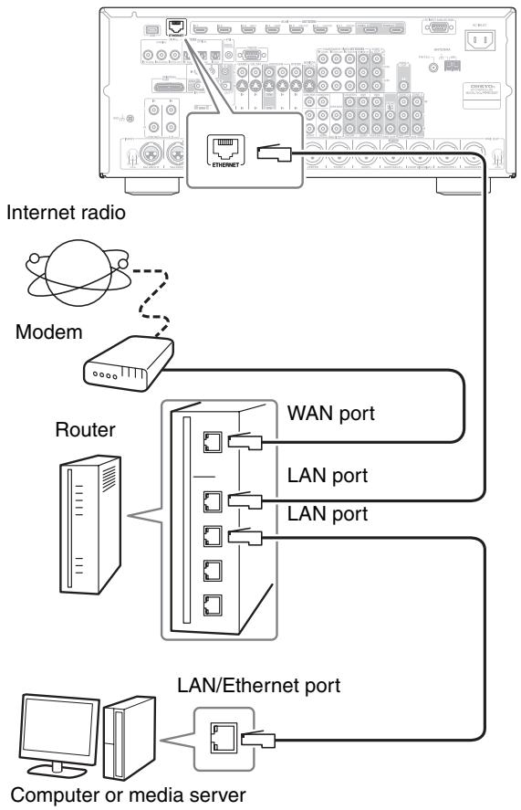
Listening to Internet Radio
To receive Internet radio, you must connect the AV controller to a network with Internet access (page 115).
You can select Internet radio stations by connecting to the AV controller from your computer and selecting stations in your Web browser. Preset up to 40 Internet radio stations.
Internet radio URLs in the following formats are supported: PLS, M3U, and podcast (RSS). However, depending on the type of data or audio format used by the Internet radio station, you may not be able to listen to some stations.
vTuner Internet Radio
- This unit includes the full vTuner Internet Radio Service at no additional charge. Once you have connected your unit to the Internet you can select vTuner Internet Radio to search for and play Internet radio stations and podcasts at any time. To enhance your Internet radio experience, the http://onkyo.vtuner.com/ portal is available to you as an easy way to browse to find stations, set up/organize your favorites, add your own stations, get help, etc. After the first time you try Internet radio/vTuner on your unit you can use the MAC Address of your unit to create a member login account (email address and password) on the http://onkyo.vtuner.com/ portal. To verify your MAC Address, please see Network Settings (page 121).
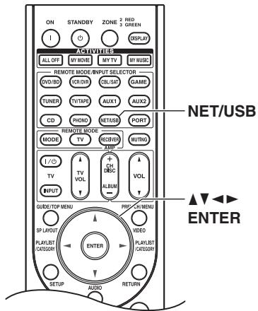

1
Press the [NET/USB] button repeatedly to select the Internet Radio screen.
![ONKYO PR-SC5507 - Press the [NET/USB] button repeatedly to select the Internet Radio screen. - 1](/content/2025/01/151815/images/087f6fd51933ffe8bf60212d38d4d83abdb0592748a47c622d051b37cbaefcba.jpg)
2
The NETWORK indicator lights up. When the program setting is finished, go to step 3.
Notes:
- When it flashes, confirm the network connection.
- Services available may vary depending on the region. See the separate instructions for more information.
On your computer, start your Web browser and enter the AV controller's IP address in the browser's Internet address (URL) field.
The browser connects to the AV controller and displays the same screen as the AV controller.
Select the Internet radio station with your browser.
Notes:
- The AV controller's IP address is shown on the "Network" screen (see page 121).
- If you're using DHCP, your router may not always allocate the same IP address to the AV controller, so if you find that you can't connect to the AV controller, recheck the AV controller's IP address on "Network" screen.

3
Use the Up and Down [▲]/[▼] buttons to select a program, and then press [ENTER].
Playback starts and the following screen appears.
All Stations
![ONKYO PR-SC5507 - Use the Up and Down [▲]/[▼] buttons to select a program, and then press [ENTER]. - 1](/content/2025/01/151815/images/954dd837ceb573516304c82884fdc2546d7ca7b4dbd24117113f75d80f4e28ef.jpg)
.
![ONKYO PR-SC5507 - Use the Up and Down [▲]/[▼] buttons to select a program, and then press [ENTER]. - 2](/content/2025/01/151815/images/926b788b3f3ea1a9da2ff16343c1ff2c2d3d3cd6d6e6861c39eefe325da9ffc4.jpg)
1.fm indieie 104
![ONKYO PR-SC5507 - Use the Up and Down [▲]/[▼] buttons to select a program, and then press [ENTER]. - 3](/content/2025/01/151815/images/9a1e3cba16ddcc8371814aa44f30f7bb706609de531d42b8cb9a9c0e93395c09.jpg)
The internet's best source for i
0:00:00
Once you've added a station to the list, simply select it on the Internet Radio screen, and then press [ENTER] to start playback.
Note:
If you're using a narrowband Internet connection (e.g., 56K modem or ISDN), depending on the station, Internet radio may not work satisfactorily. For best results, use a broadband connection (e.g., cable modem, xDSL modem, etc).
Playing Music Files on a Server
This section explains how to play music files on a computer or media server through the AV controller. See pages 119 to 120 for details on supported music servers and music file formats.
For Windows Media Player 11, see "Windows Media Player 11 Setup" on page 118.
1
Start your computer or media server.
2

Press the [NET/USB] button to select the Server screen.
![ONKYO PR-SC5507 - Press the [NET/USB] button to select the Server screen. - 1](/content/2025/01/151815/images/4368af81f418bab640944ecc9fe6edefd6f71a34adb145e0b8bb01ed6332c3cc.jpg)
The NETWORK indicator lights up.
Notes:
- When it flashes, confirm the network connection.
- To update the screen, press the [RETURN] button.
3

Use the Up and Down [▲]/[▼] buttons to select a server, and then press [ENTER].
A list of items on the server appears.
![ONKYO PR-SC5507 - Use the Up and Down [▲]/[▼] buttons to select a server, and then press [ENTER]. - 1](/content/2025/01/151815/images/e4f9e5250aefa763008e518c0a4f8297e6f2ea1d39179bebcf191a03a6857f40.jpg)
Search
You can search for music by Artist, Album, or Track.
Notes:
- The search function does not work with media servers which do not support this function.
Depending on the sharing settings in the media server, the AV controller may not be able to access the content. Refer to the instruction manual of the media server.
4

Use the Up and Down [▲]/[▼] buttons to select an item, and then press [ENTER].
A list of music files appears.
![ONKYO PR-SC5507 - Use the Up and Down [▲]/[▼] buttons to select an item, and then press [ENTER]. - 1](/content/2025/01/151815/images/f8ee4c1eb24a4a7412113811c50b8e9054bc5245d2070e94f48389f8a3a32a88.jpg)
5
![ONKYO PR-SC5507 - Use the Up and Down [▲]/[▼] buttons to select an item, and then press [ENTER]. - 2](/content/2025/01/151815/images/25327403fc33c524741c90bb685bd2acb15a0cd5740608989fd83576473ebea5.jpg)
Use the Up and Down [] / [] buttons to select a music file, and press the [ENTER] or Play [▶] button to start playback.
Playback starts and the following screen appears.
My favorite song 1
4/10
My favorite song 1
Artist name
My favorite album
0:00:00
MP3 0kbps 0kHz

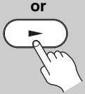
To return to the previous menu during playback, press the [RETURN] button. To stop playback, press the Stop [■] button.
To select the next song, press the Next [▶▶I] button. To select the beginning of the current song, press the Previous [I←] button. To select the previous song, press the Previous [I<▶] button twice.
To pause playback, press the [■] button. To fast forward the current song, press the [▶▶] button. To fast reverse the current song, press the [▲▼] button.
Note:
For some sort of media server, Fast Forward/Fast Reverse/Pause operations do not work.
Random Playback
The Random function can only be set while the PLAY screen is displayed.
To play songs in random order, during playback (or while playback is paused or stopped), press the [RAN-DOM] button. All of the songs in the current folder will be played in random order. When all of the songs in the folder have been played once, they'll all be played again in a different random order. To cancel random playback, press the [RANDOM] button again.
Random playback supports up to 20,000 songs per folder. If a folder contains more than this, songs over 20,000 are not included in random playback.
Repeat Playback
The Repeat function can only be set while the PLAY screen is displayed.
To play songs repeatedly, during playback (or while playback is paused or stopped), press the [REPEAT] button repeatedly to select: Repeat1, Repeat Folder, Repeat All, or Off.
In Repeat1 mode, the current song is played repeatedly. In Repeat Folder mode, all of the songs in the current folder are played repeatedly.
In Repeat All mode, all of the songs on the current server are played repeatedly.
To cancel repeat playback, press the [REPEAT] button repeatedly to select Off.
Note:
If the message "No Item." appears, this means that no information can be retrieved from the server. In this case, check your server, network, and AV controller connections.
This section explains how to configure Windows Media Player 11 so that the AV controller can play the music files stored on your computer.
Windows Media Player 11 Setup
| 1 | Start Windows Media Player 11. |
| 2 | On the Library menu, select Media Sharing. The Media Sharing dialog box appears. |
| 3 | Select the Share my media check box, and then click OK. |
| 4 | Select the AV controller in the list, and then click Allow. |
| 5 | Click OK to close the dialog box. This completes the Windows Media Player 11 configuration. You can now play the music files in your Windows Media Player 11 library through the AV controller (see page 117). |
Note:
Windows Media Player 11 can be downloaded for free from the Microsoft Web site.
Supported Audio File Formats
For server playback, the AV controller supports the following music file formats: MP3, WMA, WAV, FLAC, Ogg Vorbis, AAC and LPCM.
MP3
- MP3 files must be MPEG-1/MPEG-2 Audio Layer 3 format with a sampling rate of 8kHz , 11.025kHz , 12kHz , 16kHz , 22.05kHz , 24kHz , 32kHz , 44.1kHz , 48kHz and a bit-rate of between 8 kbps and 320 kbps. Incompatible files cannot be played.
Number of channels: 2 - Variable bit-rate (VBR) MP3 files are supported. (Playing times may not display correctly.)
- MP3 files must have a“.mp3” or“.MP3” filename extension.
WMA
WMA stands for Windows Media Audio and is an audio compression technology developed by Microsoft Corporation. Audio can be encoded in WMA format by using Windows Media Player.
- WMA files must have the copyright option turned off.
- Sampling rates of 8kHz , 11.025kHz , 12kHz , 16kHz , 22.05kHz , 24kHz , 32kHz , 44.1kHz , 48kHz and bitrates of between 5 kbps and 320 kbps, and WMA DRM are supported. Incompatible files cannot be played.
Number of channels: 2 - Variable bit-rates (VBR) are supported. (Playing times may display incorrectly with VBR.)
- WMA Pro/Voice formats are not supported.
- WMA files must have a“.wma” or“.WMA” filename extension.
WMA Lossless
- Sampling rates of 44.1kHz , 48kHz , 88.2kHz , 96kHz and bitrates of between 5 kbps and 320 kbps are supported. Incompatible files cannot be played.
- Quantization bit: 16 bit, 24 bit
Number of channels: 2 - Variable bit-rates (VBR) are supported. (Playing times may display incorrectly with VBR.)
- WMA files must have a“.wma” or“.WMA” filename extension.
WAV
WAV files contain uncompressed PCM digital audio.
- Sampling rates of 8kHz , 11.025kHz , 12kHz , 16kHz , 22.05kHz , 24kHz , 32kHz , 44.1kHz , 48kHz , 64kHz , 88.2kHz , and 96kHz are supported. Incompatible files cannot be played.
- Quantization bit: 8 bit, 16 bit, 24 bit
Number of channels: 2 - WAV files must have a“.wav” or“.WAV” filename extension.
AAC
AAC stands for MPEG-2/MPEG-4 Audio.
- Sampling rates of 8kHz , 11.025kHz , 12kHz , 16kHz , 22.05kHz , 24kHz , 32kHz , 44.1kHz , 48kHz , 64kHz , 88.2kHz , 96kHz and bitrates of between 8 and 320 kbps, are supported. Incompatible files cannot be played.
Number of channels: 2 - Variable bit-rate (VBR) files are supported. (Playing times may not display correctly.)
AAC files must have a“.aac”,“.m4a”,“.mp4”,“.3gp”,“.3g2”,“.AAC”,“.M4A”,“.MP4”,“.3GP” or“.3G2” filename extension.
FLAC
FLAC is a file format for lossless audio data compression.
- Sampling rates of 8kHz , 11.025kHz , 12kHz , 16kHz , 22.05kHz , 24kHz , 32kHz , 44.1kHz , 48kHz , 64kHz , 88.2kHz , and 96kHz are supported. Incompatible files cannot be played.
- Quantization bit: 8 bit, 16 bit, 24 bit
Number of channels: 2 - Variable bit-rates (VBR) are supported. (Playing times may display incorrectly with VBR.)
- FLAC files must have a“.flac” or“.FLAC” filename extension.
Ogg Vorbis
- Sampling rates of 8kHz , 11.025kHz , 12kHz , 16kHz , 22.05kHz , 24kHz , 32kHz , 44.1kHz , 48kHz and bitrates of between 48 kbps and 500 kbps are supported. Incompatible files cannot be played.
Number of channels: 2 - Variable bit-rates (VBR) are supported. (Playing times may display incorrectly with VBR.)
- Ogg Vorbis files must have a ".ogg" or ".OGG" filename extension.
LPCM (Linear PCM)
- Sampling rates of 8kHz , 11.025kHz , 12kHz , 16kHz , 22.05kHz , 24kHz , 32kHz , 44.1kHz , 48kHz , 64kHz , 88.2kHz , and 96kHz are supported.
- Quantization bit: 8 bit, 16 bit, 24 bit
Number of channels: 2
Server Requirements
The AV controller can play digital music files stored on a computer or media server and supports the following technologies:
- Windows Media Player 11
- Windows Media Connect 2.0
- DLNA-certified media server
If the operating system of your computer is Windows Vista, Windows Media Player 11 is already installed. Windows Media Player 11 for Windows XP can be downloaded for free from the Microsoft Web site.
- The computer or media server must be on the same network as the AV controller.
Each folder may contain up to 20,000 music files, and folders may be nested up to 16 levels deep.
Note:
For some sort of media server, the AV controller may not be able to recognize it, or may not be able to play stored music files.
Minimum system requirements for Windows Media Player 11 for Windows XP
Operating system
Windows XP Home Edition (SP2), Windows XP Professional (SP2), Windows XP Tablet PC Edition (SP2), Update Rollup 2 for Windows XP Media Center Edition 2005 (KB900325), October 2006 Update Rollup for Windows XP Media Center Edition (KB925766)
Processor: 233 MHz Intel Pentium II, Advanced Micro Devices (AMD), etc.
Memory: 64 MB
Hard disk: 200 MB of free space
Drive: CD or DVD drive
Modem: 28.8 kbps
Sound card: 16-bit sound card
Monitor: Super VGA (800× 600)
Video card: 64 MB VRAM, DirectX 9.0b
Software: Microsoft ActiveSync (only when using a Windows Mobile-based Pocket PC or smartphone)
Web browser: Microsoft Internet Explorer 6 or Netscape 7.1
About DLNA
The Digital Living Network Alliance is an international, cross-industry collaboration. Members of DLNA develop a concept of wired and wireless interoperable networks where digital content such as photos, music, and videos can be shared through consumer electronics, personal computers, and mobile devices in and beyond the home. The AV controller certificate the DLNA Interoperability Guidelines version 1.5.
Network Settings
Note:
When modifying network settings, after modifying it is necessary to execute "Save".
This section explains how to configure the AV controller's network settings manually.
If your router's DHCP server is enabled, you don't need to change any of these settings, as the AV controller is set use DHCP to configure itself automatically by default (i.e., DHCP is set to Enable). If, however, your router's DHCP server is disabled, for example, you're using static IP addresses, you'll need to configure these settings yourself, in which case, a knowledge of Ethernet networking is essential.
What's DHCP?
DHCP (Dynamic Host Configuration Protocol) is used by routers, computers, the AV controller, and other devices to automatically configure themselves on a network.
What's DNS?
The DNS (Domain Name System) translates domain names into IP addresses. For example, when you enter a domain name such as www.onkyousa.com in your Web browser, before accessing the site, your browser uses DNS to translate this into an IP address, in this case 63.148.251.142.
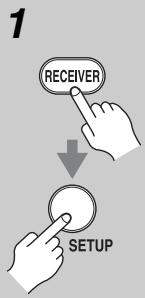
Press the [RECEIVER] button, followed by the [SETUP] button.
The main menu appears onscreen. If the main menu doesn't appear, make sure the appropriate external input is selected on your TV.
![ONKYO PR-SC5507 - Press the [RECEIVER] button, followed by the [SETUP] button. - 1](/content/2025/01/151815/images/31d07ce507b8e82dc9b8284fc7e75a5b097da036e1e6058124bf205e239f0e07.jpg)
Use the Up and Down [] / [] buttons to select "7. Hardware Setup", and then press [ENTER].
The "Hardware Setup" menu appears.
7.Hardware Setup
1Remote ID
1. Remote ID 2. Multi Zone
2. Multi Zone
3. Tuner
4.HDMI
5Network
6. Firmware Update

3
Use the Up and Down [] / [] buttons to select "5. Network", and then press [ENTER].
The "Network" screen appears.
7-5. Network
MAC Address xx:xx:xx-yy:yy:yy DHCOP Enable
IP Address:
Subnet Mask
Cabinet mask
Gateway
DNS Server
aaaabbccc 1
aaa.bbb.ccc.dda
aaa.bbb.ccc.ddd
aaa.bbb.ccc.ddd
Proxy URL http://www-proxy.xxx.com
Proxy Port

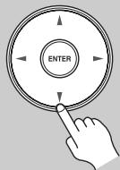
4
Use the Up and Down [ ] / [ ] buttons to select the setting, and use the Left and Right [ ] / [ ] buttons to set them.
To enter an IP address, select the setting, and then press [ENTER]. The arrow [] / [] / [] / [] buttons can then be used to enter numbers. Press [ENTER] again to set the number.
The settings are explained below.

5
When you've finished, press the [RETURN] button.
The save confirmation screen appears.
7-5. Network
Save
Cancel

6
Use the Up and Down [▲]/[▼] buttons to select "Save", and then press [ENTER].
When modifying network settings, after modifying it is necessary to execute "Save".
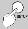
7
When you've finished, press the [SETUP] button.
The setup menu closes.
Note:
This procedure can also be performed on the AV controller by using its [SETUP] button, arrow buttons, and [ENTER] button.
Mac Address
This is the AV controller's MAC (Media Access Control) address. This address cannot be changed.
DHCP
This setting determines whether or not the AV controller uses DHCP to automatically configure its IP Address, Subnet Mask, Gateway, and DNS Server settings.
Enable: DHCP enabled.
Disable: DHCP disabled.
If you select "Disable", you must configure the "IP Address", "Subnet Mask", "Gateway", and "DNS Server" settings yourself.
IP Address
If you set the "DHCP" setting to "Disable", you must specify an IP address. Enter a static IP address provided by your ISP.
The IP address must be within the following ranges.
Class A: 10.0.0.0 to 10.255.255.255
Class B: 172.16.0.0 to 172.31.255.255
Class C: 192.168.0.0 to 192.168.255.255
Most routers use Class C IP addresses.
Subnet Mask
If you set the "DHCP" setting to "Disable", you must specify a subnet mask address.
Enter the subnet mask address provided by your ISP (typically: 255.255.255.0).
Gateway
If you set the "DHCP" setting to "Disable", you must specify a gateway address.
Enter the gateway address provided by your ISP.
DNS Server
If you set the "DHCP" setting to "Disable", you must specify a DNS server.
Enter the DNS server addresses provided by your ISP.
Proxy URL
To use a Web proxy, enter its URL here.
Proxy Port
If you're using a Web proxy, enter a proxy port number here.
Control
This setting enables or disables control over the network.
Enable: Control over the network enabled.
Disable: Control over the network disabled.
Note:
When set to "Enable", power consumption on standby mode slightly increases.
Port Number
This is the network port used for control over the network.
Note:
Set the port number between from "49152" to "65535".
About USB
USB can be used to play music files stored on USB mass storage devices (e.g., USB flash drives and MP3 players), which can be plugged into the AV controller's USB port.
Supported Audio File Formats
For USB mass storage device playback, the AV controller supports music file formats.
See "Supported Audio File Formats" on page 119.
USB Mass Storage Device Requirements
- The AV controller supports USB devices that support the USB mass storage device class.
- Playback may not be possible with some USB devices even if they conform to the USB mass storage device class.
- USB devices formatted with the FAT16 or FAT32 file system are supported.
- If the storage device has been partitioned, each section will be treated as an independent device.
Each folder may contain up to 20,000 music files and folders, and folders may be nested up to 16 levels deep. - USB hubs and USB devices with hub functions are not supported.
Playing Music Files on a USB Device
This section explains how to play music files on a USB mass storage device.
| 1 | Plug your USB mass storage device into the AV controller's USB port. |
| 2 | Press the [NET/USB] button repeatedly to select the USB(Front) or USB(Rear) screen. |
| USB(Front) | |
| USB Storage | |
| 1/1 | |
| The USB indicator lights up if the AV controller is able to read the USB mass storage device. The USB indicator flashes if the AV controller cannot read the USB mass storage device. |

3
Use the Up and Down [▲]/[▼] buttons to select a USB mass storage device, and then press [ENTER].
A list of the device's contents appears.

To open a folder, use the Up and Down [] / [] buttons to select it, and then press [ENTER].
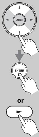
4
Use the Up and Down [ ] / [ ] buttons to select a music file, and press the [ENTER] or Play [▶] button to start playback.
Playback starts and the following screen appears.
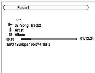
To return to the previous menu during playback, press the [RETURN] button.
To stop or pause playback, press the Stop [■] or Pause [■] button, respectively.
To select the next song, press the Next [▶▶] button. To select the beginning of the current song, press the Previous [I▶] button. To select the previous song, press the Previous [I▶] button twice.
To fast forward the current song, press the [ ] button. To fast reverse the current song, press the [ ] button.
Random Playback
The Random function can only be set while the PLAY screen is displayed.
To play songs in random order, while the list of songs is displayed, press the [RANDOM] button. All of the songs in the current folder will be played in random order.
When all of the songs in the folder have been played once, they'll all be played again in a different random order. To cancel random playback, press the [RAN-DOM] button again.
Random playback supports up to 20,000 songs per folder. If a folder contains more than this, songs over 20,000 are not included in random playback.
RepeatPlayback
The Repeat function can only be set while the PLAY screen is displayed.
To play songs repeatedly, during playback (or while playback is paused or stopped), press the [REPEAT] button repeatedly to select: Repeat1, Repeat Folder, Repeat All, or Off.
In Repeat1 mode, the current song is played repeatedly. In Repeat Folder mode, all of the songs in the current folder are played repeatedly.
In Repeat All mode, all of the songs on the USB mass storage device (in the same partition) are played repeatedly.
To cancel repeat playback, press the [REPEAT] button repeatedly to select Off.
Notes:
- If you connect a USB hard disk drive to the AV controller's USB port, we recommend that you use its AC adapter to power it.
- Do not connect the AV controller's USB port to a USB port on your computer. Music on your computer cannot be played through the AV controller in this way.
- The AV controller supports USB MP3 players that support the USB Mass Storage Class standard, which allows USB storage devices to be connected to computers without the need for special drivers or software. Note that not all USB MP3 players support the USB Mass Storage Class standard. Refer your USB MP3 player's instruction manual for details.
- Protected WMA music files on an MP3 player cannot be played.
- Onkyo accepts no responsibility whatsoever for the loss or damage to data stored on a USB mass storage device when that device is used with the AV controller. We recommend that you back up your important music files beforehand.
- MP3 players containing music files that are managed with special music software, and the iPod containing music files managed with iTunes are not supported.
- Operation with all USB mass storage devices including the ability to power them is not guaranteed.
-
Do not connect your USB mass storage device via a USB hub. The USB mass storage device must be connected directly to the AV controller's USB port.
-
If the USB mass storage device contains a lot of data, the AV controller make take a while to read it.
- USB memory devices with security functions cannot be played.
Multiroom Capability
You can use three speaker systems with this AV controller—a surround-sound speaker system (up to 9.2 channels) in your main listening room, Zone 2: a stereo speaker system in a second room, Zone 3: a stereo speaker system in a third room. And, you can select a different audio source for each room.
Main room: Enjoy up to 9.2-channel surround-sound playback (see page 18).
You can enjoy the various listening modes, such as Dolby, DTS, and THX (see pages 75 to 85).
Zone 2: In your Zone 2 room, you can enjoy 2-channel stereo playback and video playback (see page 126).
Zone 3: In your Zone 3 room, you can enjoy 2-channel stereo playback (see page 127).
- The listening modes cannot be used with Zone 2/3.
- External power amplifier required.
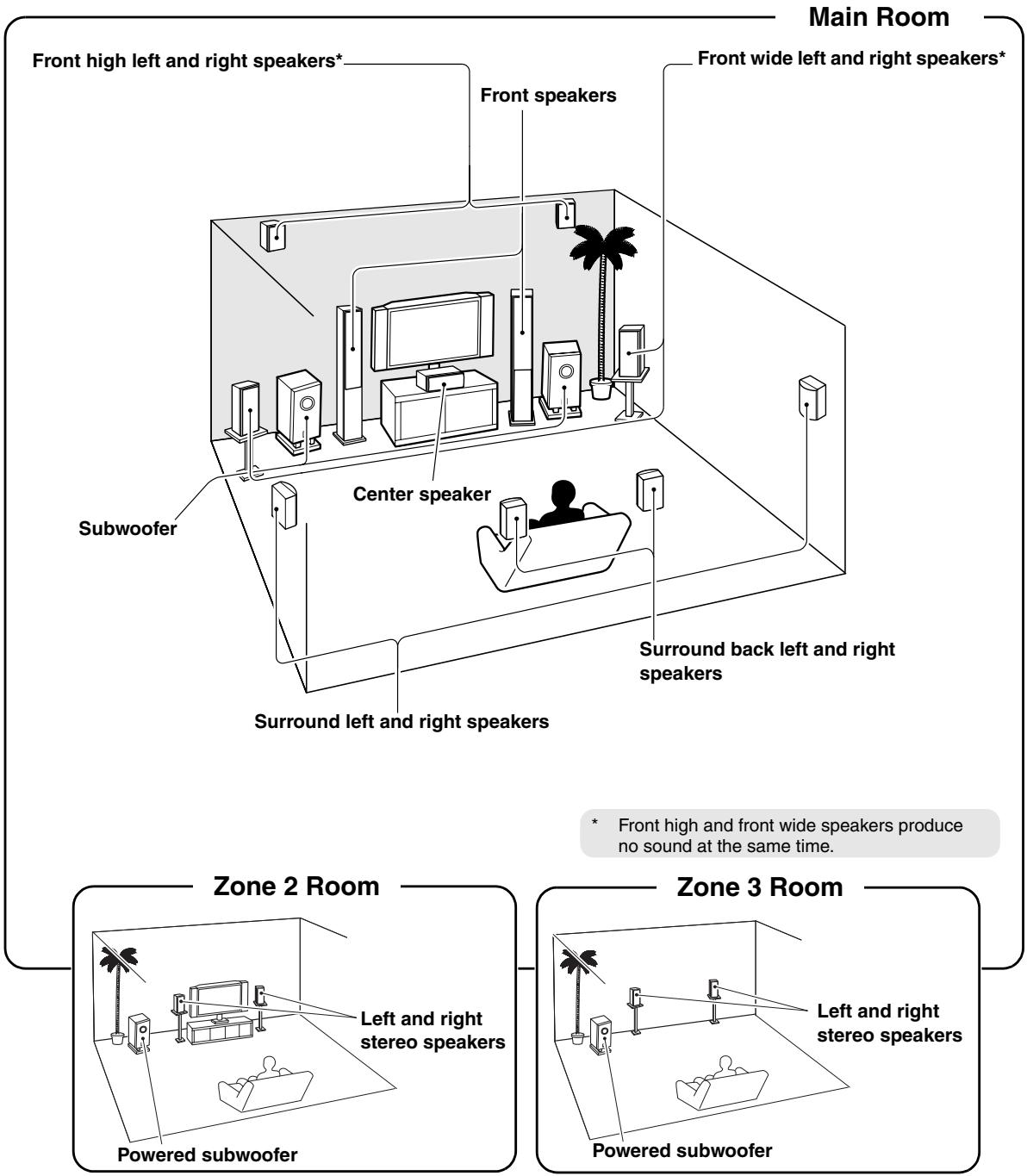
In addition to your main listening room, you can also enjoy playback in the other room, or as we call Multi Zone. And, you can select a different source for each room.
Connecting Zone 2
Zone 2 speakers must be connected to an amp in Zone 2.
Connecting Your Zone 2 Speakers
You can enjoy 2-channel stereo playback in Zone 2 and a different source to those selected for your main room and Zone 3.
Hookup
- Use an RCA audio cable to connect the AV controller's ZONE 2 PRE OUT L/R jacks to an analog audio input on your Zone 2 amp.
- Use an RCA audio cable to connect the AV controller's ZONE 2 PRE OUT SW jack to the line input on a powered subwoofer in Zone 2.
- Connect your Zone 2 speakers to the speaker terminals on your Zone 2 amp.
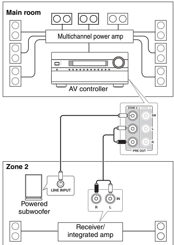
Note:
With the default settings, the Zone 2 volume must be set on the Zone 2 amp. If your Zone 2 amp has no volume control, set the "Zone2 Out" setting to "Variable" so that you can set the Zone 2 volume on the AV controller (see page 128).
Zone 2 Video Outputs
The AV controller features a composite video output and component video output for connection to a TV in Zone 2, so you can enjoy both audio and video in that zone.
Hookup
- Use a composite video cable to connect the AV controller's ZONE 2 OUT V jack to a composite video input on your Zone 2 TV.
- Alternatively, use a component video cable to connect the AV controller's COMPONENT VIDEO ZONE 2 OUT jacks to a component video input on your Zone 2 TV.
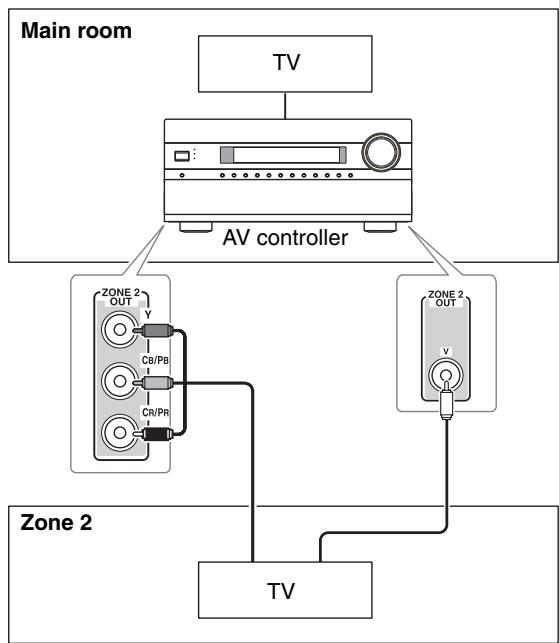
- If you use the COMPONENT Video ZONE 2 OUT, you must set the "Zone2 Component Out" setting to "Use" (page 128).
Notes:
- The ZONE 2 OUT V jack outputs video from components connected to composite video inputs.
- If you use the ZONE 2 OUT, you must set the "Zone2 Component Out" setting to "Use" (page 128). The ZONE 2 OUT outputs video only from components connected to component video inputs.
Connecting Zone 3
Zone 3 speakers must be connected to an amp in Zone 3.
Connecting Your Zone 3 Speakers
You can enjoy 2-channel stereo playback in Zone 3 and a different source to those selected for your main room and Zone 2.
Hookup
- Use an RCA audio cable to connect the AV controller's ZONE 3 PRE OUT L/R jacks to an analog audio input on your Zone 3 amp.
- Use an RCA audio cable to connect the AV controller's ZONE 3 PRE OUT SW jack to the line input on a powered subwoofer in Zone 3.
- Connect your Zone 3 speakers to the speaker terminals on your Zone 3 amp.
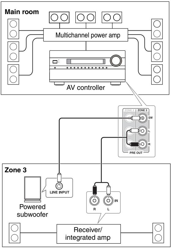
Note:
With the default settings, the Zone 3 volume must be set on the Zone 3 amp. If your Zone 3 amp has no volume control, set the "Zone3 Out" setting to "Variable" so that you can set the Zone 3 volume on the AV controller (see page 128).
Setting the Multi Zone
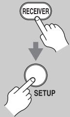
1
Press the [RECEIVER] button followed by the [SETUP] button.
The main menu appears onscreen.
If the main menu doesn't appear, make sure the appropriate external input is selected on your TV.
![ONKYO PR-SC5507 - Press the [RECEIVER] button followed by the [SETUP] button. - 1](/content/2025/01/151815/images/2a5f929cbedb0ab8ac5d29cebae0ab720ea28e57eed738c3b3ef84b20f346866.jpg)
2
Use the Up and Down [ ] / [ ] buttons to select "7. Hardware Setup", and then press [ENTER].
The "Hardware Setup" menu appears.
7. Hardware Setup
1 Remote ID
2. Multi Zone
2. Taus
3. Luner
4. HUJAN
4.HDMI 1.
5. Network
6. Firmware Update
Use the Up and Down [ ] / [ ] buttons to select "2. Multi Zone", and then press [ENTER].
The "Multi Zone" menu appears.
7-2. Multi Zone
Zone2 Out
Zone2 Maximum Volume
Zone2 Maximum Volume Zone2 Power On Volume
Zone2 Power On Volume Zone2 Component Out
Zone2 Component Out Zone3 Out
Zone Out
Zone3 Maximum volume
Zone3 Power On Volume
Fixed
Off
on Last
East Use
Use Fixed
Fixed
Off
Last
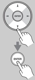
3
Use the Up and Down [ ] / [ ] buttons to select an item, and use the Left and Right [ ] / [ ] buttons to change it.
The items are explained below.
![ONKYO PR-SC5507 - Use the Up and Down [ ] / [ ] buttons to select an item, and use the Left and Right [ ] / [ ] buttons to change it. - 1](/content/2025/01/151815/images/ec9c27957bb26b658af1216e7bcd568476027a7b9ef192f4e0edf155607f6183.jpg)
4
![ONKYO PR-SC5507 - Use the Up and Down [ ] / [ ] buttons to select an item, and use the Left and Right [ ] / [ ] buttons to change it. - 2](/content/2025/01/151815/images/dd82199ea231358b4fbe3e52ddd5d75a19b3ac4de435364d198b8beeb190752c.jpg)
5
When you've finished, press the [SETUP] button.
The setup menu closes.
Note:
This procedure can also be performed on the AV controller by using its [SETUP] button, arrow buttons, and [ENTER] button.
Zone2/3 Out
If you've connected your Zone 2/3 speakers to an amp with no volume control, set the "Zone2 Out" and "Zone3 Out" setting, respectively, to "Variable" so that you can set the volume, balance, and tone of zone 2/3 on the AV controller.
Fixed: The Zone 2/3 volume must be set on the amp in that zone (default).
Variable: The Zone 2/3 volume can be set on the AV controller.
Zone2/3 Maximum Volume
With this setting, you can limit the maximum volume for Zone 2/3. When the "Volume Display" setting is set to "Absolute", the "Maximum Volume" range is 50 to 99. When it's set to "Relative", the range is -32 dB to +17 dB. To disable this setting, select "Off".
Zone2/3 Power On Volume
This setting determines what the volume will be for Zone 2/3 each time the AV controller is turned on.
When the "Volume Display" preference is set to "Absolute", the range is "Last", "Min", 1 to 99, or "Max".
When it's set to "Relative", the range is "Last", - dB, -81 dB to +18 dB.
To use the same volume level as when the AV controller was last turned off, select "Last".
The "Zone2/3 Power On Volume" cannot be set higher than the "Zone2/3 Maximum Volume" setting.
Zone2 Component Out
If you've connected the COMPONENT VIDEO ZONE 2 OUT to a TV in Zone 2, this setting is set to "Use".
Use: Select if a TV in Zone 2 is connected the COMPONENTVIDEOZONE2OUT.
Not Use: Select if no TV in Zone 2 is connected the COMPONENTVIDEO ZONE 2 OUT.
Note:
If the "Zone2 Component Out" setting is set to "Not Use", the same video signal as COMPONENT VIDEO MONITOR OUT is output from ZONE2 OUT (component).
Using Zone 2/3
This section explains how to turn Zone 2/3 on and off, how to select an input source for Zone 2/3, and how to adjust the volume for Zone 2/3.
Controlling Zone 2/3 from the AV controller
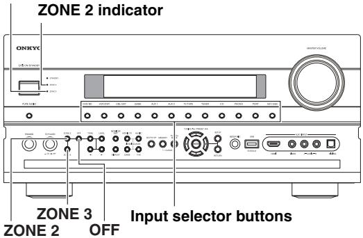
ZONE 3 indicator
1
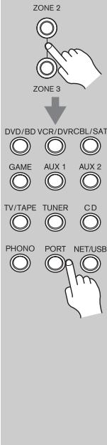
To turn on Zone 2/3 and select an input source, press the [ZONE 2] or [ZONE 3] button followed by an input selector button within 8 seconds.
Zone 2/3 turns on, the ZONE 2/3 indicator lights up.
Tip:
The 12V TRIGGER OUT ZONE 2/3 goes high (+12V)
To select AM or FM press the [TUNER] input selector and the [ZONE 2] or [ZONE 3] button repeatedly. You can also select SIRIUS (North American models).
To select the same source as that of the main room, press the [ZONE 2] or [ZONE 3] button twice. "Zone 2 Selector: Source" or "Zone 3 Selector: Source" appears on the display.
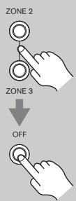
2
To turn off Zone 2/3, press the [ZONE 2] or [ZONE 3] button.
The ZONE 2 or ZONE 3 indicator flashes.
Press the [OFF] button.
The zone is turned off, and the ZONE 2 or ZONE 3 indicator goes off.
Note:
When Zone 2/3 is turned off, the output from the 12V TRIGGER OUT ZONE 2/3 goes low (0 volts).
Controlling Zone 2/3 with the Remote Controller
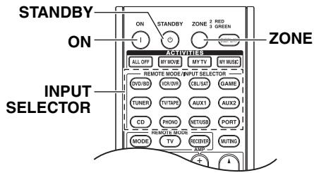
Note:
To control Zone 2/3, you must press the remote controller's [ZONE] button first.
The ZONE button turns red while Zone 2 is on, and green while Zone 3 is on.

1
ZONE
Press the [ZONE] button repeatedly, then point the remote controller at the AV controller and press the [ON] button.
Tip:
The 12V TRIGGER OUT ZONE 2/3 goes high (+12V)

2
ZONE
To select an input source for Zone 2/3, press the [ZONE] button repeatedly, followed by an INPUT SELECTOR button.
To select AM or FM press the [TUNER] INPUT SELECTOR and the [ZONE] button repeatedly. You can also select SIRIUS (North American models).

INPUT SELECTOR
DVD/BD (VCR/DVR)
CBL/SAT) GAME
TUNER TV/TAPE
AUX1 AUX2
PORT CD
PHONO (NET/USB)

3
ZONE
To turn off Zone 2/3, press the [ZONE] button repeatedly, followed by the [STANDBY] button.
Notes:
- Only analog input sources are output by the ZONE 2 PRE OUT and ZONE 3 PRE OUT. Digital input sources are not output. If no sound is heard when an input source is selected, check if it's connected to an analog input.
- You cannot select different AM or FM radio stations for your main room and Zone 2/3. The same AM/FM radio station will be heard in each room. For example, if you have an FM station for the main room, that station will also be used in Zone 2.
- When the input selector of Zone 2/3 is selected, power consumption on standby mode slightly increases.
While Zone 2/3 is on, R functions will not work.
Adjusting the Volume for Zones
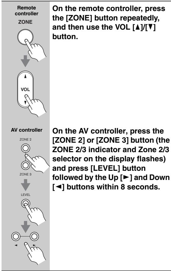
Muting Zones
| Remote controller ZONE | On the remote controller, press the [ZONE] button repeatedly, and then press the [MUTING] button. To unmute a zone, on the remote controller, press the [ZONE] button, and then press the [MUTING] button again. |
Adjusting the Tone and Balance of Zones
| 1 AV controller | On the AV controller, press the [ZONE 2] or [ZONE 3] button. |
| 2 TONE | Press the AV controller's [TONE] button repeatedly to select "Bass", "Treble" or "Balance". |
| 3 | Use the Up [▶] and Down [▲] buttons to adjust the bass, treble or balance. • You can boost or cut the bass or treble from -10 dB to +10 dB in 2 dB steps. • You can adjust the balance from 0 in the center to +10 dB to the right or +10 dB to the left in 2 dB steps. |
Notes:
- Zones can also be unmuted by adjusting the volume.
- The volume, tone and balance functions cannot be set when the "Zone2 Out" or "Zone3 Out" setting is set to "Fixed" (page 128).
- Even if you repeatedly press the remote controller's [ZONE] button to select zones, the last zone selection will be retained once you have switched to other components by pressing other REMOTE MODE buttons after pressing the [ZONE] button.
Using the 12V Triggers
The 12V triggers A, B, and C can be used to turn on 12V trigger-capable components automatically when they are selected as the input source. The triggers can be set so that they activate when a connected component is selected as the input source for the main room, Zone 2, Zone 3, or any combination of rooms.
When triggered, the output from a 12V TRIGGER OUT goes high (+12 volts and 150 milliamperes max. at TRIGGER OUT A; +12 volts and 25 milliamperes max. at TRIGGER OUT B and C).
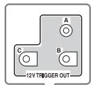
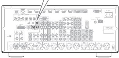
Hookup
- Use a miniplug cable to connect the AV controller's 12V TRIGGER OUT A, B, or C jack to the 12~V trigger input on a connected component.
When several components are turned on simultaneously by using triggers A, B, and C, depending on the type of components, a large amount of current may be drawn momentarily. To prevent this, you can delay trigger signals A, B, and C individually. Another application for trigger delay is eliminating the "thump" noise that's sometimes heard when a source component is turned on. Delaying the trigger signal for your power amplifier so that it's the last component to be turned on will accomplish this.
1
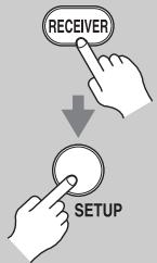
Remote controller
Press the [RECEIVER] Remote Mode button, followed by the [SETUP] button.
The main menu appears onscreen. If the main menu doesn't appear, make sure the appropriate external input is selected on your TV.
![ONKYO PR-SC5507 - Press the [RECEIVER] Remote Mode button, followed by the [SETUP] button. - 1](/content/2025/01/151815/images/ff9ff956a1e834e1526dae6d0c3a1d8581e99a0c969d59ea6ce398a71ee76dd1.jpg)
Use the Up and Down [] / [] buttons to select
"6. Miscellaneous", and then press [ENTER].
The "Miscellaneous" menu appears.
3

Use the Up and Down [ ] / [ ] buttons to select "12V Trigger A, B, or C Setup", and then press [ENTER].
The "12V Trigger A/B/C Setup" screen appears.
| 6-3. 12V Trigger A Setup | |
| Delay | 0sec → |
| DVD/BD | Main |
| VCR/DVR | Main |
| CBL/SAT | Main |
| GAME | Main |
| AUX 1 | Main |
4
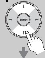
Use the Up and Down [ ] / [ ] buttons to select "Delay", and use the Left and Right [] / [] buttons to select:
0sec(TriggerA:default),
1sec (Trigger B: default),
2sec (Trigger C: default),
or 3sec.
When 0 sec is selected, the trigger signal is output as soon as the input source is changed.
![ONKYO PR-SC5507 - Use the Up and Down [ ] / [ ] buttons to select "Delay", and use the Left and Right [] / [] buttons to select: - 1](/content/2025/01/151815/images/ce79f5643d96196b0f6e99e73e7e10b2b8a8e3495cc0f57ca6bfa05f75cc8f2a.jpg)
5
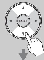
Use the Up and Down [ ] / [ ] buttons to select an input source, and use the Left and Right [ ]/ [▶] buttons to select an option. Off:
No trigger signal is output.
A 12-volt trigger signal is output when the connected component is selected as the source for:
Main (Trigger A: default):
Main room.
Zone2 (Trigger C: default): Zone 2.
Main/Zone2:
Main room or Zone 2.
Zone3:
Zone 3.
Main/Zone3:
Main room or Zone 3.
Zone2/Zone3:
Zone 2 or Zone 3.
Main/Zone2/Zone3 (Trigger B: default):
Main room, Zone 2, or Zone 3.
6
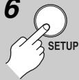
When you've finished, press the [SETUP] button.
The setup menu closes.
Using the Remote Controller in Zone 2/3 and Multiroom Control Kits
To control the AV controller with the remote controller while you're in Zone 2 or Zone 3, you'll need a commercially available multiroom remote control kit for each zone.
- Multiroom kits are made by Niles and Xantech.
These kits can also be used when there isn't a clear line of sight to the AV controller's remote sensor, such as when it's installed inside a cabinet.
Using a Multiroom Kit with Zone 2/3
In this setup, the IR receiver in Zone 2/3 picks up the infrared signals from the remote controller and feeds them through to the AV controller in the main room via the connecting block.
The miniplug cable from the connecting block should be connected to the AV controller's IR IN A or B jack, as shown below. The IR IN A and B jacks are identical. Up to two IR receivers can be connected.
Using a Multiroom Kit with a Cabinet
In this setup, the IR receiver picks up the infrared signals from the remote controller and feeds them to the AV controller located in the cabinet via the connecting block.
Using a Multiroom Kit with Other Components
In this setup, an IR emitter is connected to the AV controller's IR OUT jack and placed in front of the other component's remote control sensor. Infrared signals received at the AV controller's IR IN A or B jack are fed through to the other component via the IR emitter. Signals picked up by the AV controller's remote control sensor are not output.
The IR emitter should be connected to the AV controller's IR OUT jack, as shown below.
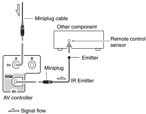
You can use the AV controller's remote controller (RC-747M) to control your other AV components, including those made by other manufacturers. This section explains how to enter the remote control code for a component that you want to control: DVD, TV, VCR, etc.
- Learn commands directly from another component's remote controller (see page 146).
- Program the ACTIVITIES buttons to perform a sequence of up to 32 remote control actions (see page 147).
Preprogrammed Remote Control Codes
The following REMOTE MODE buttons are preprogrammed with remote control codes for controlling the components listed. You do not need to enter a remote control code to control these components.
For details on controlling these components, see the pages indicated.

Onkyo DVD player (page 138)

Onkyo CD player (page 141)

Onkyo cassette recorder with RI (page 143)
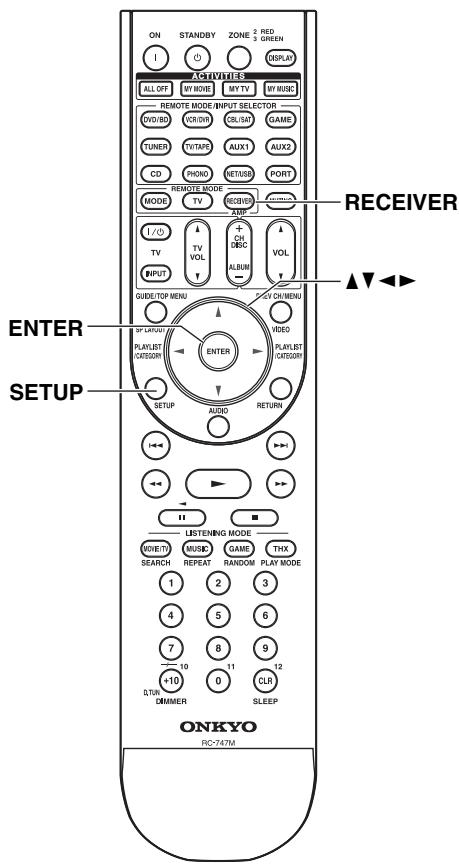
Looking up for Remote Control Code
You can look up for appropriate remote control code from onscreen setup menu.
Note:
This setting can be carried out by using Onscreen Setup Menu only.
Press the [RECEIVER] button followed by the [SETUP] button.
The main menu appears onscreen. If the main menu doesn't appear, make sure the appropriate external input is selected on your TV.
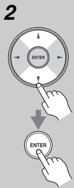
Use the Up and Down [A]/[V] buttons to select "8. Remote Controller Setup", and then press [ENTER].
-
Remote Controller Setup
-
Remote Mode Setup
- Activities Setup
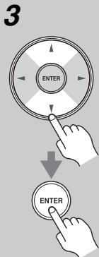
Use the Up and Down [A]/[V] buttons to select "1. Remote Mode Setup", and then press [ENTER].
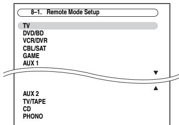
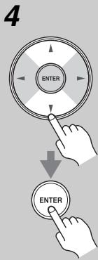
Use the Up and Down [A]/[V] buttons to select remote mode, and then press [ENTER].
The category selection menu appears.
8-1. Remote Mode Setup
TV
TV
TV/BVD
TV/VCR
5
Use the Up and Down [A]/[V] buttons to select category, and then press [ENTER].
The brand name input panel appears.

6
Use the arrow [ ] / [ ] / [ ] / [ ] buttons to select a character, and then press [ENTER].
Repeat this step from the 1st character to the 3rd character of the brand name.
When you have entered the 3rd character, select "Search" and press [ENTER].
After searching, a list of the brand name appears.
If the brand name is not found:
Use the Right [▶] button to select "Not Listed", and then press [ENTER].
The brand name input panel appears.
7
Use the Up and Down [A]/[V] buttons to select brand, and then press [ENTER].
After searching is completed, a message for remote control code transfer will appear.
To use the remote controller, point it at the AV controller's remote control sensor, as shown below.
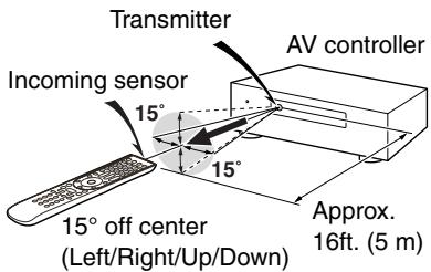
On the remote controller press the [ENTER] button.
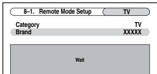
When the transfer is successful, the following screen appears. Try it.
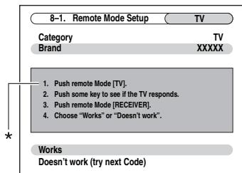
- When category other than TV have been selected, the content is different.
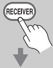
8
If you can control component, press the [RECEIVER] button, use the Up and Down [A]/[V] buttons to select "Works", and then press [ENTER].
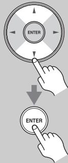
The "Remote Mode Setup" menu appears.
If you cannot control component, use the Up and Down [A]/[V] buttons to select "Doesn't work (try next Code)" and press [ENTER].
The next code is appear.

9
When you've finished, press the [SETUP] button.
The setup menu closes.
Entering Remote Control Codes
You'll need to enter a code for each component that you want to control.
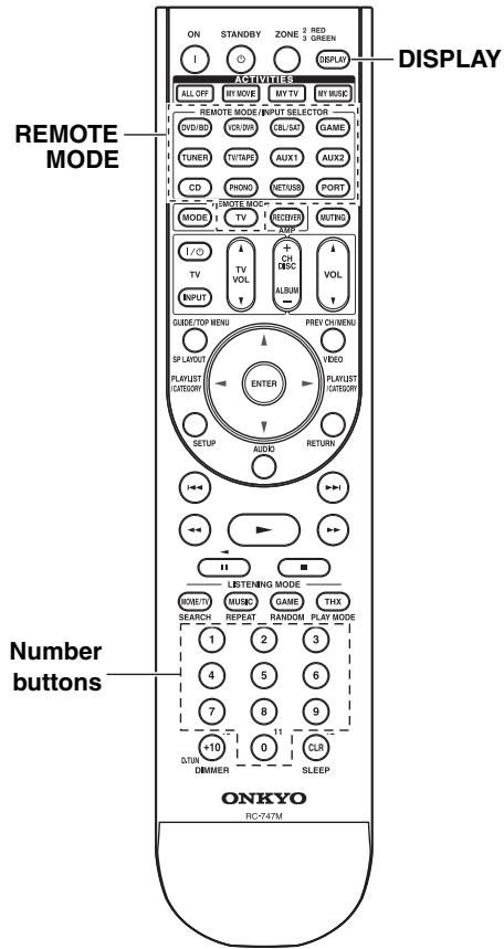
1
Look up the appropriate remote control code in the separate Remote Control Codes list.
The codes are organized by category (e.g., DVD player, TV, etc.).
2
REMOTE MODE
DVD/BD VCR/DVR
(CBL/SAT) (GAME)
TUNER TV/TAPES
TANAL
AUX1 AUX2
PORT CD
PHONO NET/USB
PANO
IV
(3 seconds)
While holding down the REMOTE MODE button to which you want to enter a code, press and hold down the [DISPLAY] button (about 3 seconds).
The REMOTE MODE button lights up.
Notes:
- Remote control codes cannot be entered for the [RECEIVER] and [ZONE] buttons.
- Only TV remote control codes can be entered for the [TV] button.
Except for the [RECEIVER], [TV], and [ZONE] buttons, remote control codes from any category can be entered for the REMOTE MODE buttons. However, these buttons also work as input selector buttons (page 62), so choose a REMOTE MODE button that corresponds with the input to which you connect your component. For example, if you connect your CD player to the CD input, choose the [CD] button when entering its remote control code.
3
①
4 5 6
7 8 9

Within 30 seconds, use the number buttons to enter the 5-digit remote control code.
The REMOTE MODE button flashes twice.
If the remote control code is not entered successfully, the REMOTE MODE button will flash once slowly.
Note:
The remote control codes provided are correct at the time of printing, but are subject to change.
Remote Control Codes for Onkyo Components Connected via RI
Onkyo components that are connected via RI are controlled by pointing the remote controller at the AV controller, not the component. This allows you to control components that are out of view, in a rack, for example.
1 Make sure the Onkyo component is connected with an R1 cable and an analog audio cable (RCA).
See page 42 for details.
2 Enter the appropriate remote control code for the REMOTE MODE button.
- [DVD/BD] button
31612: Onkyo DVD player with Rl
- [CD] button
71327: Onkyo CD player with Rl
- [TV/TAPE] button
42157: Onkyo cassette recorder with RI (default)
- [PORT] button
82351: Onkyo Dock (default)
See the previous page for how to enter remote control codes.
3 Press the REMOTE MODE button, point the remote controller at the AV controller, and operate the component.
If you want to control an Onkyo component by pointing the remote controller directly at it, or you want to control an Onkyo component that's not connected via RI, use the following remote control codes:
- [DVD/BD] button
30627: Onkyo DVD player without Rl (default)
- [CD] button
71817: Onkyo CD player without RI (default)
- [TV] button
11807: TV with R1HD (default)
If you want to control an Onkyo component by pointing the remote controller directly at it, use the following remote control codes:
32900: Onkyo BD player
32901: Onkyo HD DVD player
70868: Onkyo MD recorder
71323: Onkyo CD recorder
81993: Onkyo RI Dock with RI
Note:
If you connect an RI-capable Onkyo RI Dock to the TV/TAPE, VCR/DVR, or GAME jacks, for RI to work properly, you must set the Input Display accordingly (see page 55).
Resetting REMOTE MODE Buttons
You can reset a REMOTE MODE button to its default remote control code.
1 While holding down the REMOTE MODE button that you want to reset, press and hold down the [AUDIO] button until the REMOTE MODE button lights up (about 3 seconds).
2 Within 30 seconds, press the REMOTE MODE button again. REMOTE MODE DVD/BD VCR/DVR CBL/SAT GAME TUNER TV/TAPE AUX1 AUX2 PORT CD PHONO NET/USB TV Note: The learning command is also reset.
Resetting the Remote Controller
You can reset the remote controller to its default settings.
1 While holding down the [RECEIVER] button, press and hold down the [AUDIO] button until the [RECEIVER] button lights up (about 3 seconds).
(3 seconds)
2 Within 30 seconds, press the [RECEIVER] button again. The [RECEIVER] button flashes twice, indicating that the remote controller has been reset.
Controlling a TV
By pressing the [TV] button that's been programmed with the remote control code for TV, you can control your TV with the following buttons.
For details on entering a remote control code for a different component, see page 135.
The [TV] button is preprogrammed with the remote control code for controlling a TV that supports the
RIHD ^*1 (limited to some models). The TV must be able to receive remote control commands via RIHD and be connected to the AV controller via HDMI. If controlling your TV via RIHD doesn't work very well, program your TV's remote control code into the [TV] button and use the TV remote mode to control your TV.
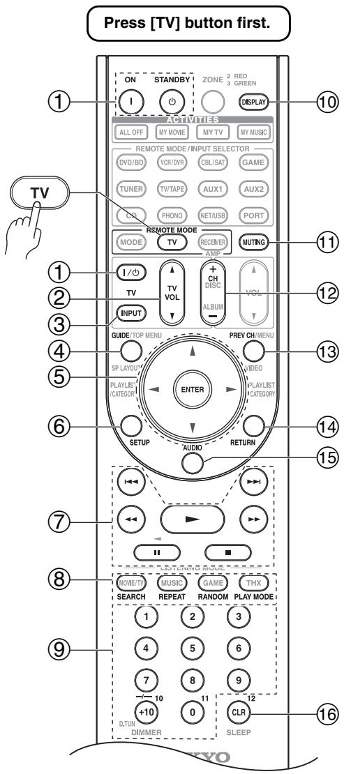
*1 The RiHD supported by the AV controller is the CEC system control function of the HDMI standard.
① ON, STANDBY, TV [I/0] buttons Set the TV to On or Standby.
② TV VOL [▲]/[▼] button Adjust the TV's volume.
③ TV [INPUT] button
Selects the TV's external inputs.
④ GUIDE button Displays the program guide.
^⑤ Arrow [ ] / [ ] / [< ] / [> and ENTER buttons Used to navigate menus and select items.
⑥ SETUP button Displays a menu.
⑦ [▶], [■], [■], [▲], [▶], [■▲], [▶]
buttons
Play, Pause, Stop, Fast reverse, Fast forward, Previous, and Next.
These buttons work for combination devices.
SEARCH, REPEAT, RANDOM, and PLAY MODE buttons Function as colored buttons or A, B, C, D buttons.
⑨ Number buttons Enter numbers. 0 button enters 11 on some components. +10 button works as “--/---” button or +10.
10 DISPLAY button Displays information.
⑪ MUTING button Mutes the TV.
CH +/- button Select channels on the TV.
PREV CH button Selects the previous or last channel.
14 RETURN button Exits the TV's setup menu.
15 AUDIO button* Selects foreign language soundtracks and audio formats (e.g., Dolby Digital or DTS).
16 CLR button Cancels functions and clears entered numbers, or enters 12.
Notes:
- With some components, certain buttons may not work as expected, and some may not work at all.
- Buttons marked with an asterisk (*) are not supported by the R1HD function.
Controlling a DVD Player or DVD Recorder
By pressing the REMOTE MODE button that's been programmed with the remote control code for your DVD player (HD DVD, Blu-ray, or TV/DVD combination), you can control your player with the following buttons. The [DVD/BD] button is preprogrammed with the remote control code for controlling an Onkyo DVD player.
For details on entering a remote control code for a different component, see page 135.
The [DVD/BD] button is preprogrammed with the remote control code for controlling a component that supports the RIHD ^1 . The component must be able to receive remote control commands via RIHD and be connected to the AV controller via HDMI. If controlling your component via RIHD doesn't work very well, program your component's remote control code into the [DVD/BD] button and use the DVD/BD remote mode to control your component.
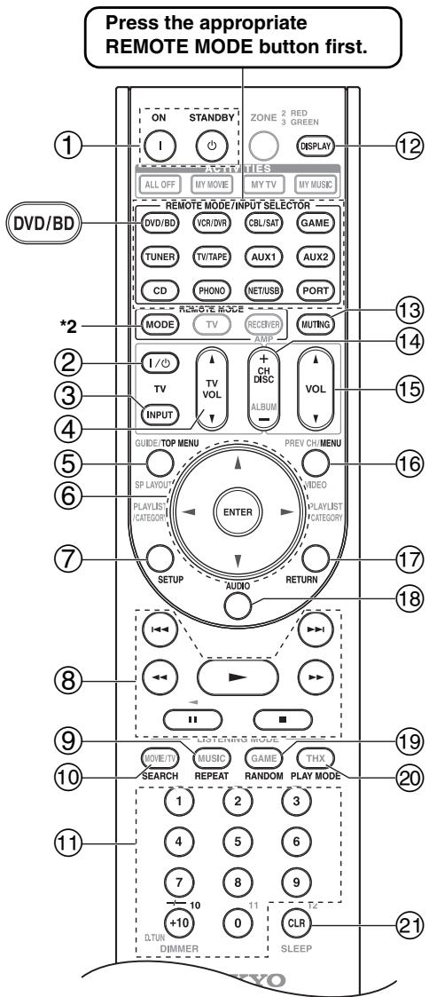
*1 The RUIHD supported by the AV controller is the CEC system control function of the HDMI standard.
*2 When you want to change the remote controller mode without changing the current input source, press the [MODE] button and within about eight seconds, press the REMOTE MODE button. Then, with the AV controller's remote controller, you can control the component corresponding to the button you pressed.
① ON, STANDBY buttons
Sets the DVD player to On or Standby.
② TV [I/O] button
Set the TV to On or Standby.
③ TV [INPUT] button
Selects the TV's external inputs.
④ TV VOL [▲]/[▼] button
Adjust the TV's volume.
⑤ TOP MENU button
Displays a DVD's top menu or a DVD's title.
⑥ Arrow [] / [] / [] / [] and ENTER buttons
Used to navigate menus and select items.
⑦ SETUP button
Used to access the DVD player's settings.
8 [▶], [■], [■], [▲], [▶], [i], [▶] buttons
Play, Pause, Stop, Fast reverse, Fast forward, Previous, and Next.
⑨ REPEAT button
Used with the repeat playback functions.
SEARCH button*
Used to search title, chapter, and track numbers, and to search times for locating specific points.
1 Number buttons
Used to enter title, chapter, and track numbers, and to enter times for locating specific points. The [+10] button* works as a +10 button or - - / - - ^ 一 button.
12 DISPLAY button
Displays information about the current disc, title, chapter, or track, including elapsed time, remaining time, total time, and so on.
⑬ MUTING button (64)
Mutes or unmutes the AV controller.
CH +/-, DISC +/- button
Selects discs on a DVD changer. Selects TV channels on a component with a built-in tuner.
⑤ VOL [▲]/[▼] button (62)
Adjusts the volume of the AV controller.
16 MENU button
Displays a DVD's menu.
RETURN button
Expires the DVD player's setup menu or returns to the previous menu.
18 AUDIO button*
Selects foreign language soundtracks and audio formats (e.g., Dolby Digital or DTS).
19 RANDOM button*
Used with the random playback function.
20 PLAY MODE button\*
Selects play modes on components with selectable play modes.
② CLR button
Cancels functions and clears entered numbers.
Notes:
- With some components, certain buttons may not work as expected, and some may not work at all.
Controlling a VCR or PVR
By pressing the REMOTE MODE button that's been programmed with the remote control code for your VCR (TV/VCR, PVR, DBS/PVR combination or cable/PVR combination), you can control your video recorder with the following buttons.
For details on entering a remote control code for a different component, see page 135.
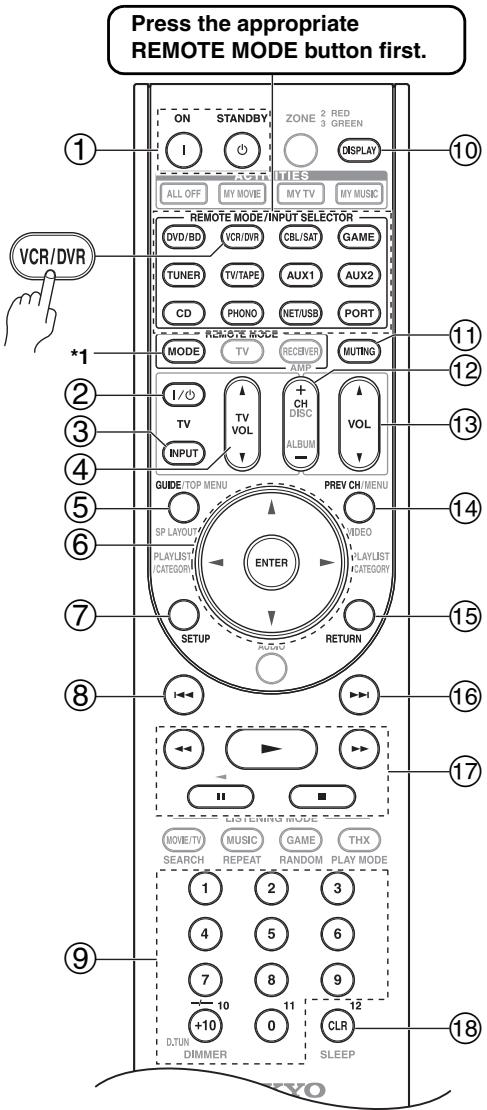
*1 When you want to change the remote controller mode without changing the current input source, press the [MODE] button and within about eight seconds, press the REMOTE MODE button. Then, with the AV controller's remote controller, you can control the component corresponding to the button you pressed.
- If you enter the remote control code for a HD DVD or Blu-ray player that has A, B, C, and D or colored buttons, the [SEARCH], [REPEAT], [RANDOM], and [PLAY MODE] buttons will work as colored or A, B, C, D buttons. In this case, these buttons cannot be used to set repeat playback, random playback, or select play modes.
- Buttons marked with an asterisk (*) are not supported by the R1HD function.
① ON, STANDBY buttons
Set the video recorder to On or Standby.
② TV [I/O] button
Set the TV to On or Standby.
③ TV [INPUT] button
Selects the TV's external inputs.
④ TV VOL [▲]/[▼] button
Adjust the TV's volume.
⑤ GUIDE button
Displays the program guide or navigation list.
⑥ Arrow [▲]/[▼]/[▲]/[▶] and ENTER buttons
Used to navigate menus and select items.
⑦ SETUP button
Displays the video recorders setup menu.
⑧ Previous [↓←] button
Previous or instant replay function.
Number buttons
Enter numbers. The [0] button enters 11 on some components. The [+10] button works as a +10 button or - - / - - ^ button.
10 DISPLAY button
Displays information.
① MUTING button (64)
Mutes or unmutes the AV controller.
CH+/-button
Selects TV channels on the video recorder.
⑬ VOL [▲]/[▼] button (62)
Adjusts the volume of the AV controller.
14 PREV CH button
Selects the previous channel.
15 RETURN button
Exits the menu or returns to the previous menu.
16 Next [▶i] button
Next or advance function.
⑦ [▶], [■], [■], [▲], [▲▶] buttons
Play, Pause, Stop, Fast reverse, and Fast forward.
18 CLR button
Cancels functions or enters the number 12.
Note:
With some components, certain buttons may not work as expected, and some may not work at all.
Controlling a Satellite Receiver or Cable Receiver
By pressing the REMOTE MODE button that's been programmed with the remote control code for your satellite receiver, cable receiver, or DVD recorder (DBS/PVR combination or cable/PVR combination), you can control your player with the following buttons.
For details on entering a remote control code for a different component, see page 135.
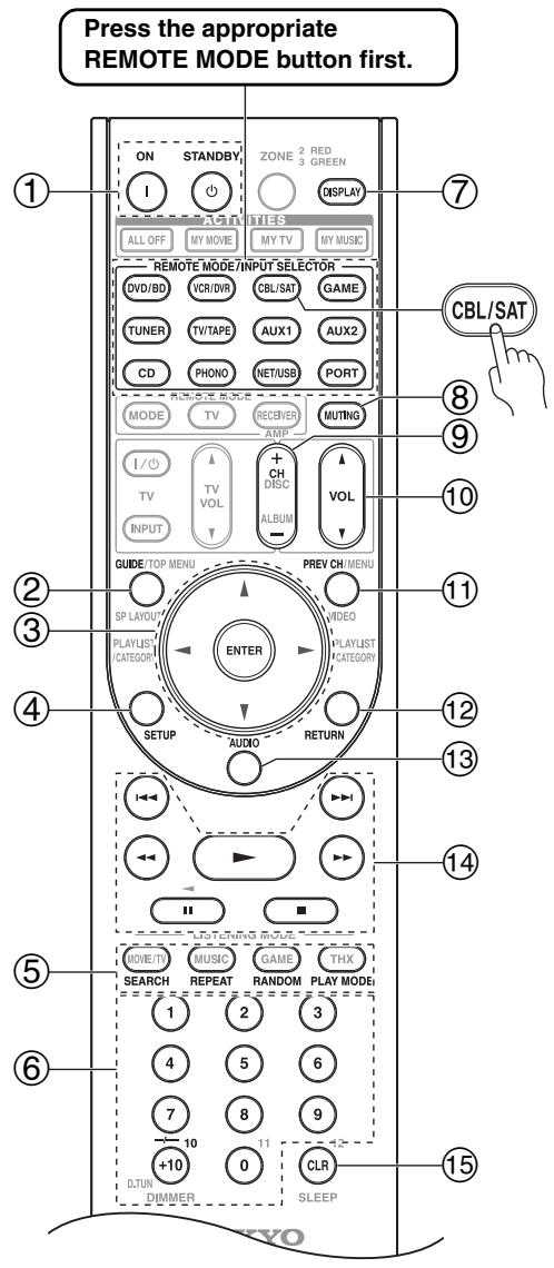
① ON, STANDBY buttons
Set the component to On or Standby.
② GUIDE button
Displays the onscreen program guide.
③ Arrow [▲]/[▼]/[▲]/[▶] and ENTER buttons
Used to navigate menus and select items.
④ SETUP button
Displays the setup menu.
⑤ SEARCH, REPEAT, RANDOM, and PLAY MODE buttons
Function as colored buttons or A, B, C, D buttons.
⑥ Number buttons
Enter numbers. The [+10] button works as a +10 button or "--/----" button.
⑦ DISPLAY button
Displays information.
⑧ MUTING button (64)
Mutes or unmutes the AV controller.
CH +/- button
Selects satellite/cable channels.
10 VOL [ ] / [ ] button (62)
Adjusts the volume of the AV controller.
PREV CH button
Selects the previous channel.
12 RETURN button
Exits the menu.
⑬ AUDIO button
Selects foreign language soundtracks and audio formats (e.g., Dolby Digital or DTS).
14 [▶], [■], [■], [▲], [▶], [i←], [▶→] buttons
Play, Pause, Stop, Fast reverse, Fast forward, Previous, and Next.
15 CLR button
Cancels functions and clears entered numbers.
Note:
With some components, certain buttons may not work as expected, and some may not work at all.
Controlling a CD Player, CD Recorder or MD Recorder
By pressing the REMOTE MODE button that's been programmed with the remote control code for your CD player, CD recorder, or MD recorder, you can control your player with the following buttons.
The [CD] button is preprogrammed with the remote control code for controlling an Onkyo CD player.
For details on entering a remote control code for a different component, see page 135.
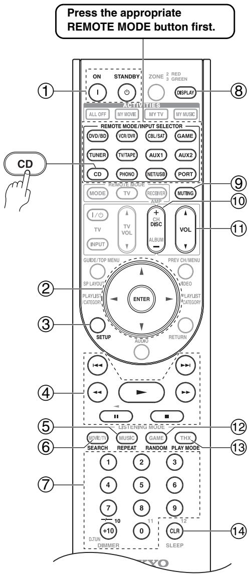
① ON, STANDBY buttons
Set the component to On or Standby.
② Arrow []/[]/[]/[] and ENTER buttons
Used to navigate menus and select items.
③ SETUP button
Used to access the Onkyo CD player's settings.
④ [▶], [■], [■], [▲▼], [▶▼], [i←▼], [▶→i] buttons
Play, Pause, Stop, Fast reverse, Fast forward, Previous, and Next.
⑤ REPEAT button
Used with the repeat playback function.
⑥ SEARCH button
Used to locate specific points.
⑦ Number buttons
Used to enter track numbers and times for locating specific points. The [+10] button works as a +10 button or "--/---" button.
⑧ DISPLAY button
Displays information about the current disc or track, including elapsed time, remaining time, total time, and so on.
(9) MUTING button (64)
Mutes or unmutes the AV controller.
10 DISC + / - button
Selects discs on a CD changer.
① VOL [] / [] button (62)
Adjusts the volume of the AV controller.
12 RANDOM button
Used with the random playback function.
13 PLAY MODE button
Selects play modes on components with selectable play modes.
⑭ CLR button
Cancels functions and clears entered numbers.
Note:
With some components, certain buttons may not work as expected, and some may not work at all.
Controlling an RI Dock
By pressing the REMOTE MODE button that's been programmed with the remote control code for your Dock, you can control your iPod in the Dock with the following buttons.
For some RI docks, the [ON], [STANDBY] button may not work with a remote control code 82990 (without RI).
In this case, make an RI connection and enter a remote control code 81993 (with RI).
For details on entering a remote control code, see page 135.
When Using an RI Dock:
- When using the Onkyo DS-A3 RI Dock, make an RI connection and enter a remote control code 81993 (with RI ).
- Connect the RI Dock to the TV/TAPE IN, VCR/DVR IN, or GAME IN L/R jacks.
- Set the RI Dock's RI MODE switch to HDD or HDD/ DOCK.
- Set the AV controller's Input Display to DOCK (see page 55).
- See to the Dock's instruction manual for more information.
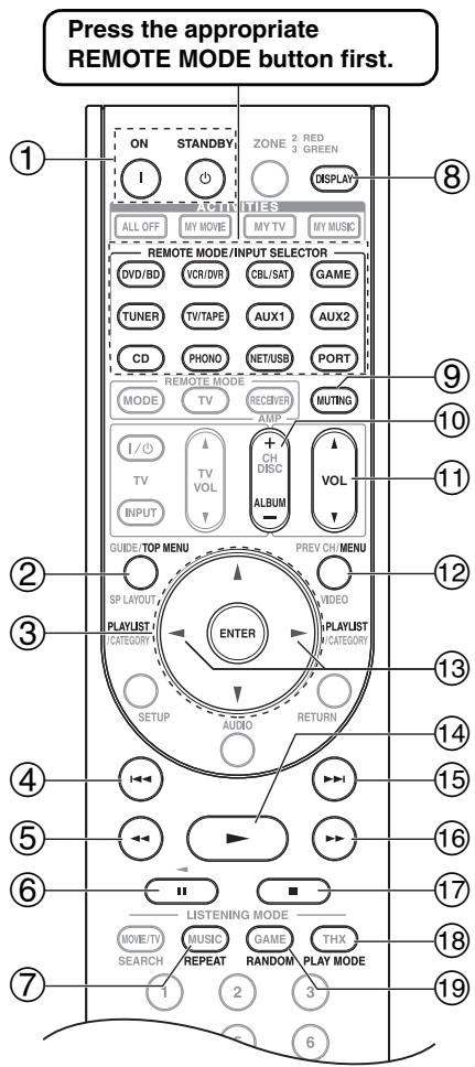
① ON, STANDBY buttons
Turns the iPod on or off.
Notes:
- This button does not turn the Onkyo DS-A2 or DS-A2X RI Dock on or off.
- Your iPod may not respond the first time you press this button, in which case you should press it again. This is because the remote controller transmits the On and Standby commands alternately, so if your iPod is already on, it will remain on when the remote controller transmits an On command. Similarly, if your iPod is already off, it will remain off when the remote controller transmits an Off command.
② TOP MENU button
Works as a Mode button when used with a DS-A2 RI Dock.
③ Arrow [] / [] and ENTER buttons
Used to navigate menus and select items.
④ Previous [←] button
Restarts the current song. Press it twice to select the previous song.
⑤ Fast Reverse [←] button
Press and hold to fast reverse.
⑥ Pause [I] button
Pauses playback.
⑦ REPEAT button
Used with the repeat function.
⑧ DISPLAY button
Turns on the backlight for 30 seconds.
⑨ MUTING button (64)
Mutes or unmutes the AV controller.
10 ALBUM + / - button
Selects the next or previous album.
⑪ VOL [▲]/[▼] button (62)
Adjusts the volume of the AV controller.
12 MENU button
Exits the menu.
⑬ PLAYLIST [<]/[▶] button
Selects the previous or next playlist on the iPod.
⑭ Play [▶] button
Starts playback. If the component is off, it will turn on automatically.
15 Next [▶▶i] button
Selects the next song.
16 Fast Forward [▶▶] button
Press and hold to fast forward.
17 Stop [■] button
Stops playback and displays a menu.
18 PLAY MODE button
Selects play modes on components with selectable play modes.
Works as a Resume button when used with a DS-A2 RI Dock.
19 RANDOM button
Used with the shuffle function.
Note:
With some components, certain buttons may not work as expected, and some may not work at all.
Controlling a Cassette Recorder
By pressing the REMOTE MODE button that's been programmed with the remote control code for your cassette recorder, you can control your cassette recorder with the following buttons.
The [TV/TAPE] button is preprogrammed with the remote control code for controlling an Onkyo cassette recorder when used with an RI connection.
For details on entering a remote control code for a different component, see page 135.
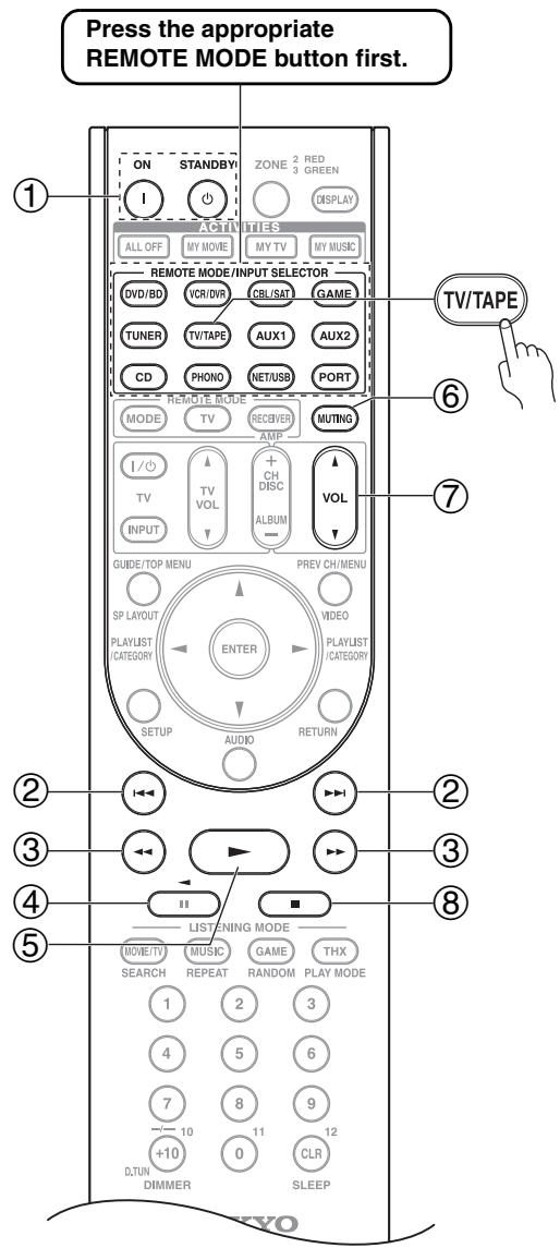
On twin cassette decks, only Deck B can be controlled.
① ON, STANDBY buttons
Turns the cassette recorder on or off.
② Previous and Next [I▲]/[▶▶] buttons
The Previous [1] button selects the previous track. During playback it selects the beginning of the current track. The Next [▶▶1] button selects the next track.
Depending on how they were recorded, the Previous and Next [1 1] / [1 1] buttons may not work properly with some cassette tapes.
③ Fast Reverse and Fast Forward [←/][▶] buttons
The Fast Reverse [<] button starts fast reverse.
The Fast Forward [▶▶] button starts fast forward.
Starts reverse playback.
⑤ Play [▶] button
Starts playback.
⑥ MUTING button (64)
Mutes or unmutes the AV controller.
⑦ VOL [] / [] button (62)
Adjusts the volume of the AV controller.
⑧ Stop [■] button
Stops playback.
Notes:
- An Onkyo cassette recorder connected via R1 can also be controlled in Receiver mode.
- With some components, certain buttons may not work as expected, and some may not work at all.
Activities Setup
Via onscreen menu, you can specify what actions will be taken by the Easy macro command in the Easy macro mode.
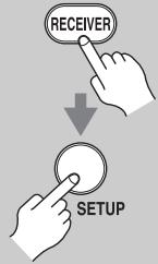
1
Press the [RECEIVER] button followed by the [SETUP] button.
The main menu appears onscreen. If the main menu doesn't appear, make sure the appropriate external input is selected on your TV.
![ONKYO PR-SC5507 - Press the [RECEIVER] button followed by the [SETUP] button. - 1](/content/2025/01/151815/images/1a13e191846eb2c9941b33b37b08a31b1253f184950c57d54b1e9b9cfd6683ec.jpg)
2
Use the Up and Down [A]/[V] buttons to select "8. Remote Controller Setup", and then press [ENTER].
The "Remote Controller Setup" menu appears.
-
Remote Controller Setup
-
Remote Mode Setup
-
Activities Setup
![ONKYO PR-SC5507 - Use the Up and Down [A]/[V] buttons to select "8. Remote Controller Setup", and then press [ENTER]. - 1](/content/2025/01/151815/images/92f0291c6e9b6cc0b1fbe75e8f2a0ee1c29b82f3fde3830dde06db597bd4cd43.jpg)
3
Use the Up and Down [A]/[V] buttons to select "2. Activities Setup", and then press [ENTER].
The "Activities Setup" menu appears.
8-2. Activities Setup
My Movie
My TV.
My Music
![ONKYO PR-SC5507 - Use the Up and Down [A]/[V] buttons to select "2. Activities Setup", and then press [ENTER]. - 1](/content/2025/01/151815/images/bd7bd075b58439916864375a6a43fd96d0477727c6742cf0ea20a679294c01ce.jpg)
4
Use the Up and Down [A]/[V] buttons to select "My Movie", "My TV", or "My Music", and then press [ENTER].
My Movie: Actions for the MY MOVIE button is changed.
My TV: Actions for the MY TV button is changed.
MyMusic: Actions for the MY MUSIC button is changed.
![ONKYO PR-SC5507 - Use the Up and Down [A]/[V] buttons to select "My Movie", "My TV", or "My Music", and then press [ENTER]. - 1](/content/2025/01/151815/images/93baff698270bb1d3fb2a4286afc17c93156bcb2d86ba452487c1bddc26ad8ff.jpg)
5
Use the Up and Down [] / [] buttons to select an item, and use the Left and Right [] / [] buttons to change the settings.
The items are explained below.
![ONKYO PR-SC5507 - Use the Up and Down [] / [] buttons to select an item, and use the Left and Right [] / [] buttons to change the settings. - 1](/content/2025/01/151815/images/c52966666f47543154d4545221589c4dec0cdc944b5b85b55bd055ac10ffc6a3.jpg)
Source
DVD/BD, VCR/DVR, CBL/SAT, GAME, AUX 1, AUX 2, TV/ TAPE, TUNER, CD, PHONO, PORT, NET/USB
With this setting, you can choose the input source.
TV Power On
Enable: TV to turn on "Enable".
Disable: TV to turn on "Disable". This option enables the TV to turn on when the ACTIVITIES button is pressed.
Source Power On
Enable: Source to turn on "Enable".
Disable: Source to turn on "Disable".
This option enables the Source to turn on when the ACTIVITIES button is pressed.
Receiver Power On
Enable: AV controller to turn on "Enable".
Disable: AV controller to turn on "Disable".
This option enables the AV controller to turn on when the ACTIVITIES button is pressed.
Receiver Source Change
Enable: AV controller input selector is change.
Disable: AV controller input selector is not change.
This option enables the AV controller input selector to change when the ACTIVITIES button is pressed.
Source Play
Enable: Start playback the source of "Enable".
Disable: Start playback the source of "Disable".
This option enables the Source to start playback when the ACTIVITIES button is pressed.
Here are the default settings.
| Items | Default Settings | ||
| My Movie | My TV | My Music | |
| Source | DVD | CBL | CD |
| TV Power On | Enable | Enable | Disable |
| Source Power On | Enable | Enable | Enable |
| Receiver Power On | Enable | Enable | Enable |
| Receiver Source Change | Enable | Enable | Enable |
| Source Play | Enable | Disable | Enable |
6

8-2. Activities Setup
My Movie
Press [ENTER].
A message for transfer will appear.
Now we are ready to transfer data to Remote
Please hold remote so that it is facing the receiver.
Use ENTER button of your remote to activate "OK".
Ready?
OK
To use the remote controller, point it at the AV controller's remote control sensor, as shown below.
![ONKYO PR-SC5507 - Press [ENTER]. - 1](/content/2025/01/151815/images/65c4ee0046a1ae8fb0d8ac870259007ef9ebc05c12f5165a2209e21862a77176.jpg)
(Left/Right/Up/Down)
![ONKYO PR-SC5507 - Press [ENTER]. - 2](/content/2025/01/151815/images/fef3f7675397d27e74a45fa4fb312d2c138f4b1d72f4df1256dae48a7ecca6aa.jpg)
7
On the remote controller press the [ENTER] button.
![ONKYO PR-SC5507 - On the remote controller press the [ENTER] button. - 1](/content/2025/01/151815/images/86333dd3fd9c83d540d8cc13bfcb95239b3eccafd091dc85ede3a120b049d47d.jpg)
When the transfer is successful, the following screen appears.
![ONKYO PR-SC5507 - On the remote controller press the [ENTER] button. - 2](/content/2025/01/151815/images/02bbb634b7cdf33d29f8540e69e8ea1ad2c3cea655554f171832c7df66268819.jpg)
![ONKYO PR-SC5507 - On the remote controller press the [ENTER] button. - 3](/content/2025/01/151815/images/0514a8513b250d855fc9a2086669f0a36b1569bdf6890b88015e54eec790def8.jpg)
8
When you've finished, press the [ENTER] button.
The "8-2. Activities Setup" menu appears onscreen.
![ONKYO PR-SC5507 - When you've finished, press the [ENTER] button. - 1](/content/2025/01/151815/images/0c2ad5de0a617ae721c60a05a64a190885495e6d4129b95cc44772dd4590b6be.jpg)
9
When you've finished, press the [SETUP] button.
The setup menu closes.
Learning Commands
The AV controller's remote controller can learn the commands of other remote controllers. By transmitting, for example, the Play command from your CD player's remote controller, the remote controller can learn it, and then transmit the exact same command when its Play [▶] button is pressed in the CD remote mode.
This is useful when you've entered the appropriate remote control code (page 135) but some buttons don't work as expected.
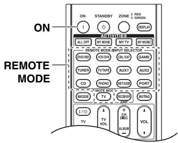
| 1 REMOTE MODE DVD/BD VCR/DVR CBL/SAT GAME TUNER TV/TAPE AUX1 AUX2 PORT CD PHONO NET/USB TV + ON I P (3 seconds) | While holding down the REMOTE MODE button for the mode in which you want to use the command, press and hold down the [ON] button until the REMOTE MODE button lights up (about 3 seconds). |
| 2 | On the supplied remote control-ler, press the button you want to learn the new command. |
| 3 | Point the remote controllers at each other, about 2 to 6 inches (5 to 15 cm) apart, and then press and hold the button whose com-mand you want to learn until the REMOTE MODE button flashes. |
| If the command is learned successfully, the REMOTE MODE button flashes twice. | |
| About 2 to 6 inches (5 to 15 cm) | |
| Supplied remote controller (RC-747M) | |
| 4 | To learn more commands, repeat steps 2 and 3. Press any REMOTE MODE button when you've finished. The REMOTE MODE button flashes twice. |
Notes:
- The following buttons cannot learn new commands: REMOTE MODE, ACTIVITIES [ALL OFF], [MY MOVIE], [MY TV], [MY MUSIC].
- The remote controller can learn approximately 70 to 90 commands, although this will be less if commands that use a lot of memory are learned.
- Remote controller buttons such as Play, Stop, Pause, and so on are preprogrammed with commands for controlling Onkyo CD players, cassette decks, and DVD players. However, they can learn new commands, and you can restore the preprogrammed commands at any time by resetting the remote controller (see page 136).
- To overwrite a previously learned command, repeat this procedure.
- Depending on the remote controller that you are using, there may be some buttons that won't work as expected, or even some remotes that cannot be learned at all.
- Only commands from infrared remote controllers can be learned.
- When the remote controller's batteries expire, all learned commands will be lost and will have to be learned all over again, so don't discard your other remote controllers.
- Deleting Learning Commands
- While holding down the REMOTE MODE button for the mode in which you want to delete the command, press and hold down the TV [1/0] button until the REMOTE MODE button lights up (about 3 seconds).
- Press the REMOTE MODE button or the button from which you want to delete the commands. The REMOTE MODE button flashes twice. When you press the REMOTE MODE button, all commands learned in that remote mode will be deleted.
Using Normal Macros
You can program the remote controller's ACTIVITIES buttons to perform a sequence of remote control actions.
Example:
To play a CD you typically need to perform the following actions:
- Press the [RECEIVER] button to select the Receiver remote controller mode.
- Press the [ON] button to turn on the AV controller.
- Press the [CD] button to select the CD input source.
- Press the Play [▶] button to start playback on the CD player.
You can program ACTIVITIES buttons so that all four actions are performed with just one button press.
Making Macros
Each ACTIVITIES button can store one macro, and each macro can contain up to 32 commands.
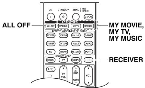
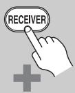
1
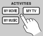
2
(3 seconds)
While holding down the [RECEIVER] button, press and hold down the [MY MOVIE], [MY TV], or [MY MUSIC] button until the MY MOVIE, MY TV, or MY MUSIC button lights up (about 3 seconds).
Press the buttons whose actions you want to program into the macro in the order you want them performed.
For the CD example above, you'd press the following buttons: [ON], [CD], Play [▶].
Note:
The [MODE] button is invalid at macro making operation.
3
When you've finished, press the ACTIVITIES button again.
The ACTIVITIES button flashes twice. If you enter 32 commands, the process will finish automatically.
Note:
Once you have taught new macro commands, the original macro will no longer work. If you want to retrieve them, you will have to teach again.
Running Macros
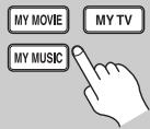
ACTIVITIES
Press the [MY MOVIE], [MY TV], or [MY MUSIC] button.
The commands in the macro are transmitted in the order in which they were programmed. Keep the remote controller pointed at the AV controller until all of the commands have been transmitted.
Macros can be run at any time, regardless of the current remote controller mode.
Deleting Macros
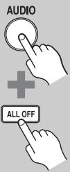
1
While holding down the [AUDIO] button, press and hold down the [ALL OFF] button until the ALL OFF button lights up (about 3 seconds).

(3 seconds)
2
Press the [ALL OFF] button again.
The ALL OFF button flashes twice.
Notes:
- All of the ACTIVITIES buttons will automatically switch to the Easy macro mode when the macro is deleted.
- When you using Normal macro mode, you cannot use the easy macro command including the change of the source component.
If you have any trouble using the AV controller, look for a solution in this section. If you can't resolve the issue yourself, contact your Onkyo dealer.
If you can't resolve the issue yourself, try resetting the AV controller before contacting your Onkyo dealer.
To reset the AV controller to its factory defaults, turn it on and, while holding down the [VCR/DVR] button, press the [ON/STANDBY] button. "Clear" will appear on the display and the AV controller will enter Standby mode.
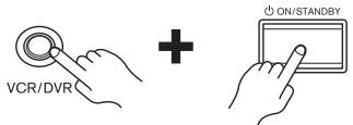
Note that resetting the AV controller will delete your radio presets and custom settings.
Power
Can't turn on the AV controller
- Make sure that the power cord is properly plugged into the wall outlet.
- Unplug the power cord from the wall outlet, wait five seconds or more, then plug it in again.
Audio
There's no sound, or it's very quiet.
- Make sure that your multichannel power amplifier is turned on and set up correctly and connected to the AV controller properly (page 17).
- Make sure that the digital input source is selected properly (page 51).
- Make sure that all audio connecting plugs are pushed in all the way (page 24).
- Make sure that the inputs and outputs of all components are connected properly (pages 27 to 41).
- Make sure that the input source is properly selected (page 62).
- Make sure that the speaker cables are not shorting.
- Check the volume. It can be set to - dB, -81.5 dB through +18.0 dB (page 62). The AV controller is designed for home theater enjoyment. It has a wide volume range, allowing precise adjustment.
- If the MUTING indicator is flashing on the display, press the remote controller's [MUTING] button to unmute the AV controller (page 64).
- While a pair of headphones is connected to the PHONES jack, no sound is output by the speakers (page 64).
-
If there's no sound from a DVD player connected to an HDMI IN, check the DVD player's output settings, and be sure to select a supported audio format.
-
Check the digital audio output setting on the connected device. On some game consoles, such as those that support DVD, the default setting is off.
- With some DVD-Video discs, you need to select an audio output format from a menu.
- If your turntable uses an MC cartridge, you must connect an MC head amp, or an MC transformer.
- Make sure that none of the connecting cables are bent, twisted, or damaged.
- Not all listening modes use all speakers (page 83).
- Specify the speaker distances (page 91) and adjust the individual speaker levels (page 92).
- Make sure that the speaker setup microphone is not still connected.
- The input signal format is set to PCM or DTS. Set it to Auto (page 111).
Only the front speakers produce sound
- When the DTS Surround Sensation, Stereo or Mono listening mode is selected, only the front speakers and subwoofer produce sound.
- In the Mono listening mode, only the front speakers output sound if the "Output Speaker" setting is set to "Left / Right" (page 94).
- Check the Speaker Configuration (page 90).
Only the center speaker produces sound
- If you use the Dolby Pro Logic IIx Movie, Dolby Pro Logic IIx Music, or Dolby Pro Logic IIx Game listening mode with a mono source, such as an AM radio station or mono TV program, the sound is concentrated in the center speaker.
- In the Mono listening mode, only the front speakers output sound if the "Output Speaker" setting is set to "Center" (page 94).
- Make sure the speakers are configured correctly (page 90).
The surround speakers produce no sound
- When the DTS Surround Sensation, T-D (Theater-Dimensional), Stereo or Mono listening mode is selected, the surround speakers produce no sound.
- Depending on the source and current listening mode, not much sound may be produced by the surround speakers. Try selecting another listening mode.
- Make sure the speakers are configured correctly (page 90).
The center speaker produces no sound
- When the DTS Surround Sensation or Stereo listening mode is selected, the center speaker produces no sound.
- In the Mono listening mode, only the front speakers output sound if the "Output Speaker" setting is set to "Left / Right" (page 94).
- Make sure the speakers are configured correctly (page 90).
The front high, front wide and surround back speakers produce no sound
- Depending on the current listening mode, no sound may be produced by the front high, front wide, and surround back speakers. Select another listening mode (page 83).
- Not much sound may be produced by the front high, front wide, and surround back speakers with some sources.
- Make sure the speakers are configured correctly (page 90).
The subwoofer produces no sound
- When you play source material that contains no information in the LFE channel, the subwoofer may produce no sound.
- Make sure the speakers are configured correctly (page 90).
There's no sound with a certain signal format
- Check the digital audio output setting on the connected device. On some game consoles, such as those that support DVD, the default setting is off.
- With some DVD-Video discs, you need to select an audio output format from a menu.
Depending on the input signal, some listening modes cannot be selected (pages 76 to 82).
Can't get 6.2/7.2 playback
- If no front high, front wide and surround back speakers are connected, or the Zone 2/3 speakers are being used, 6.2/7.2 playback is not possible.
- You can not always select all of the listening modes, depending on the number of the speakers connected (pages 76 to 82).
The speaker volume cannot be set as required (The volume cannot be set to +18.0 dB)
- Check to see if a maximum volume has been set (page 105).
- If the volume level of each individual speaker has been adjusted to high positive values (page 92), then the maximum master volume possible may be reduced. Note that the individual speaker volume levels are set automatically after Audyssey MultEQ® XT Room Correction and Speaker Setup has been completed (page 57).
Noise can be heard
- Using cable ties to bundle audio cables with power cords, speaker cables, and so on may degrade the audio performance, so don't do it.
- An audio cable may be picking up interference. Try repositioning your cables.
The Late Night function doesn't work
- Make sure the source material is Dolby Digital, Dolby Digital Plus, and Dolby TrueHD (page 112).
The analog multichannel input doesn't work
- Check the multichannel input connections (page 33).
- Make sure that the multichannel input is assigned to the input selector (page 52).
- Make sure that the multichannel input is selected (page 74).
- Check the audio output settings on your source component.
About DTS signals
- When DTS program material ends and the DTS bit-stream stops, the AV controller remains in DTS listening mode and the DTS indicator remains on. This is to prevent noise when you use the pause, fast forward, or fast reverse function on your player. If you switch your player from DTS to PCM, because the AV controller does not switch formats immediately, you may not hear any sound, in which case you should stop your player for about three seconds, and then resume playback.
- With some CD and LD players, you won't be able to playback DTS material properly even though your player is connected to a digital input on the AV controller. This is usually because the DTS bitstream has been processed (e.g., output level, sampling rate, or frequency response changed) and the AV controller doesn't recognize it as a genuine DTS signal. In such cases, you may hear noise.
- When playing DTS program material, using the pause, fast forward, or fast reverse function on your player may produce a short audible noise. This is not a malfunction.
The beginning of audio received by an HDMI IN can't be heard
- Since it takes longer to identify the format of an HDMI signal than it does for other digital audio signals, audio output may not start immediately.
Video
There's no picture
- Make sure that all video connecting plugs are pushed in all the way (page 24).
- Make sure that each video component is properly connected (pages 27 to 41).
- If your TV is connected to the HDMI output, set the "Monitor Out" setting other than "Analog" (page 47), and select "- - - - - " in the "HDMI Input Setup" on page 49 to watch composite video, S-Video, and component video sources.
- If your TV is connected to the COMPONENT VIDEO MONITOR OUT, S MONITOR OUT, or V MONITOR OUT, set the "Monitor Out" setting to "Analog" (page 47), and select "- - - - " in the "Component Video Input Setup" on page 50 to watch composite video and S-Video sources.
- If the video source is connected to a component video input, you must assign that input to an input selector (page 50), and your TV must be connected to either the HDMI OUT or COMPONENT VIDEO MONITOR OUT (pages 27 and 31).
- If the video source is connected to an HDMI input, you must assign that input to an input selector (page 49), and your TV must be connected to the HDMI outputs (page 27).
- While the Pure Audio listening mode is selected, the video circuitry is turned off and only video signals input through HDMI IN can be output.
- On your TV, make sure that the video input to which the AV controller is connected is selected.
- If you selected "Both (Main)" or "Both (Sub)" in the "Monitor Out" setting, no picture may appear on your TV that is connected to a secondary HDMI output (not a priority HDMI output). In this case, change the setting to "Both" (page 47).
There's no picture from a source connected to an HDMI IN
- Reliable operation with an HDMI-to-DVI adapter is not guaranteed. In addition, video signals from a PC are not guaranteed (page 27).
- When the "Monitor Out" setting is set to "Analog", and the "Resolution" setting is set to anything other than "Through" (page 47), no video is output by the HDMI outputs.
- When the "Resolution" (page 48) is set to any resolution not supported by the TV, no video is output by the HDMI outputs.
- If the message "Resolution Error" appears on the AV controller's display, this indicates that your TV does not support the current video resolution and you need to select another resolution on your DVD player.
The onscreen menus don't appear
- If your TV is connected to the analog outputs, set the "Monitor Out" setting to "Analog" (page 47).
- (European and Asian models) Specify the TV system used in your area in the "TV Format Setup" on page 54.
- On your TV, make sure that the video input to which the AV controller is connected is selected.
The picture is distorted
- (European and Asian models) Specify the TV system used in your area in the "TV Format Setup" on page 54.
The immediate display does not appear
- If you select other than "Analog" in the "Monitor Out" setting (page 47), the immediate display will not appear when the input signal from the COMPONENT Video IN is output to a device connected to the COMPONENT Video MONITOR OUT.
- Depending on the input signal, the immediate display may not appear when the input signal from the HDMI input is output to a device connected to the HDMI output.
Tuner
Reception is noisy, FM stereo reception is noisy, or the FM STEREO indicator doesn't appear
- Relocate your antenna.
- Move the AV controller away from your TV or computer.
- Listen to the station in mono (page 67).
- When listening to an AM station, operating the remote controller may cause noise.
Passing cars and airplanes can cause interference.
Concrete walls weaken radio signals. - If nothing improves the reception, install an outdoor antenna.
Remote Controller
The remote controller doesn't work
- Make sure that the batteries are installed with the correct polarity (page 14).
- Install new batteries. Don't mix different types of batteries, or old and new batteries (page 14).
- Make sure that the remote controller is not too far away from the AV controller, and that there's no obstruction between the remote controller and the AV controller's remote control sensor (page 14).
- Make sure that the AV controller is not subjected to direct sunshine or inverter-type fluorescent lights. Relocate if necessary.
-
If the AV controller is installed in a rack or cabinet with colored-glass doors, the remote controller may not work reliably when the doors are closed.
-
Make sure you've selected the correct remote controller mode (pages 15 and 137 to 143).
- When using the remote controller to control other manufacturers' AV components, some buttons may not work as expected.
- Make sure you've entered the correct remote control code (page 135).
- Make sure to set the same ID on both the AV controller and remote controller (page 107).
Can't control other components
- If it's an Onkyo component, make sure that the RI cable and analog audio cable are connected properly. Connecting only an RI cable won't work (page 42).
- Make sure you've selected the correct remote controller mode (pages 15 and 137 to 143).
- If you've connected an RI-capable Onkyo MD recorder, CD recorder, RI Dock to the TV/TAPE IN/OUT jacks, or an RI Dock to the GAME IN or VCR/DVR IN jacks, for the remote controller to work properly, you must set the display to MD, CDR, or DOCK (page 55).
If you cannot operate it, you will need to enter the appropriate remote control code (page 135).
- To control another manufacturer's component, point the remote controller at that component.
- If none of the codes work, use the Learning function to learn the commands of the other component's remote controller (page 146).
- With some AV components, certain buttons may not work as expected, and some may not work at all.
- To control an Onkyo component that's connected via RI, point the remote controller at the AV controller. Be sure to enter the appropriate remote control code first (page 136).
- To control an Onkyo component that's not connected via Rl, or another manufacturer's component, point the remote controller at the component. Be sure to enter the appropriate remote control code first (page 135).
- The entered remote control code may not be correct. If more than one code is listed, try each one.
Can't learn commands from another remote controller
- When learning commands, make sure that the transmitting ends of both remote controllers are pointing at each other.
- Are you trying to learn from a remote controller that cannot be used for learning? Some commands cannot be learned, especially those that contain several instructions.
Dock for iPod
There's no sound
- Make sure your iPod is actually playing.
- Make sure your iPod is inserted properly in the Dock.
- Make sure the UP-A1 Dock is connected to the UNIVERSAL PORT jack on the AV controller.
- Make sure the AV controller is turned on, the correct input source is selected, and the volume is turned up.
- Make sure the plugs are pushed in all the way.
Try resetting your iPod.
There's no video
- Make sure that your iPod's TV OUT setting is set to On.
- Make sure the correct input is selected on your TV or the AV controller.
- Some versions of the iPod do not output video.
The AV controller's remote controller doesn't control your iPod
- Make sure your iPod is properly inserted in the Dock. If your iPod is in a case, it may not connect properly to the Dock. Always remove your iPod from the case before inserting it into the Dock.
- The iPod cannot be operated while it's displaying the Apple logo.
- Make sure you've selected the right remote mode.
- When you use the AV controller's remote controller, point it toward your amp.
- If you still can't control your iPod, start playback by pressing your iPod's Play button. Remote operation should then be possible.
Try resetting your iPod. - Depending on your iPod, some buttons may not work as expected.
- You can't control your iPod if the battery is extremely low. Use the iPod after recharging for a while.
The AV controller unexpectedly selects your iPod as the input source
- Always pause iPod playback before selecting a different input source. If playback is not paused, the Direct Change function may select your iPod as the input source by mistake during the transition between tracks.
Recording
Can't record
- On your recorder, make sure the correct input is selected.
- To prevent signal loops and damage to the AV controller, input signals are not fed through to outputs with the same name (e.g., TAPE IN to TAPE OUT or VCR/DVR IN to VCR/DVR OUT).
- When the Pure Audio listening mode is selected, recording is not possible because no video signals are output. Select another listening mode.
Zone 2/3
There's no sound
- Only components connected to analog inputs can be played in Zone 2/3.
Music Server and Internet Radio
Can't access the server or Internet radio
- Check the network connection between the AV controller and your router or switch.
- Make sure that your modem and router are properly connected, and make sure they are both turned on.
- Make sure the server is up and running and compatible with the AV controller (page 120).
- Check the "Network Settings" (page 121).
Playback stops while listening to music files on the server
- Make sure your server is compatible with the AV controller (page 120).
- If you download or copy large files on your computer, playback may be interrupted. Try closing any unused programs, use a more powerful computer, or use a dedicated server.
- If the server is serving large music files to several networked devices simultaneously, the network may become overloaded and playback may be interrupted. Reduce the number of playback devices on the network, upgrade your network, or use a switch instead of a hub.
Can't connect to the AV controller from a Web browser
- If you're using DHCP, your router may not always allocate the same IP address to the AV controller, so if you find that you can't connect to a server or Internet radio station, recheck the AV controller's IP address on Network screen.
- Check the "Network settings" (page 121).
USB Mass Storage Device Playback
Can't access the music files on a USB device
- Make sure the USB device is plugged in properly.
- The AV controller supports USB devices that support the USB mass storage device class. However, playback may not be possible with some USB devices even if they conform to the USB mass storage device class.
- USB memory devices with security functions cannot be played.
Others
The sound changes when I connect my headphones
- When a pair of headphones is connected, the listening mode is set to Stereo, unless it's already set to Stereo, Mono, Direct, Pure Audio or DTS Surround Sensation.
The speaker distance cannot be set as required
- In some cases, corrected values suitable for home theater use may be set automatically.
The display doesn't work
- The display is turned off when the Pure Audio listening mode is selected.
How do I change the language of a multiplex source
- Use the "Multiplex" setting on the "Audio Adjust" menu to select "Main" or "Sub" (page 94).
The RI functions don't work
- To use RI, you must make an RI connection and an analog audio connection (RCA) between the component and AV controller, even if they are connected digitally (page 42).
- While Zone 2 or Zone 3 is selected, the RI functions don't work.
The functions Auto Power On/Standby and Direct Change don't work for components connected via RI
- These functions don't work when Zone 2/3 is turned on.
When performing "Audyssey MultEQ® XT Room Correction and Speaker Setup", the measurement fails showing the message "Ambient noise is too high."
- This can be caused by any malfunction in your speaker unit. Check if the unit produces normal sounds.
The following settings can be made for the S-Video and composite video inputs
You must use the buttons on the AV controller to make these settings.
- While holding down the input selector button for the input source that you want to set, press the [SETUP] button.
- Use the Left and Right [] / [] buttons to change the setting.
- Press the input selector button for the input source that you want to set when you've finished.
Video Attenuation
This setting can be made for the DVD/BD, VCR/
DVR, CBL/SAT, GAME or AUX1 input.
If you have a games console connected to the
S-Video and composite video input, and the picture isn't very clear, you can attenuate the gain.
Video ATT:OFF: (default).
Video ATT:ON: Gain is reduced by 2 dB.
The AV controller contains a microcomputer for signal processing and control functions. In very rare situations, severe interference, noise from an external source, or static electricity may cause it to lockup. In the unlikely event that this happens, unplug the power cord from the wall outlet, wait at least five seconds, and then plug it back in again.
Onkyo is not responsible for damages (such as CD rental fees) due to unsuccessful recordings caused by the unit's malfunction. Before you record important data, make sure that the material will be recorded correctly.
Before disconnecting the power cord from the wall outlet, set the AV controller to Standby.
Important Note Regarding Video Playback
The AV controller can upconvert component video, S-Video, and composite video sources for display on a TV connected to the HDMI outputs. However, if the picture quality of the source is poor, upconversion may make the picture worse or disappear altogether.
In this case, try the following:
1 If the video source is connected to a component video input, connect your TV to the COMPONENTVIDEOMONITOROUT.
If the video source is connected to an S-Video input, connect your TV to a MONITOR OUT S.
If the video source is connected to a composite video input, connect your TV to the MONITOR OUT V.
2 On the main menu, select "1. Input/Output Assign", and then select "2. HDMI Input".
Select the relevant input selector, and assign it to "---" (page 49).
3 On the main menu, select "1. Input/Output Assign", and then select "3. Component Video Input" (page 50).
If the video source is connected to COMPONENT Video IN1, select the relevant input selector, and assign it to "IN1".
If the video source is connected to COMPONENT Video IN2, select the relevant input selector, and assign it to "IN2".
If the video source is connected to COMPONENT Video IN3, select the relevant input selector, and assign it to "IN3".
If the video source is connected to an S-Video input or composite video input, select the relevant input selector, and assign it to "---".
If "Monitor Out" setting is set to "Analog", press [VCR/DVR] and [RETURN] buttons on the AV controller at the same time. Select "Skip" in the "VideoProcessor" setting by pressing the [RETURN] button repeatedly on the display. To reset back to the original setting, press the same button at the same time. If you select "Use", the AV controller will output video signals from the video processor.
Amplifier Section
Input Sensitivity and Impedance
200mV / 47k (LINE)
2.5 mV/47 kΩ, (PHONO MM)
Output Level and Impedance
200 mV/470 Ω (REC OUT)
Phono Overload
70mV (MM 1kHz0.5%
Frequency Response
5Hz - 100kHz / + 1 dB-3dB
(Direct mode)
Tone Control
± 10 dB, 50Hz (BASS)
± 10 dB, 20kHz (TREBLE)
Signal to Noise Ratio
110 dB (LINE, IHF-A)
80 dB (PHONO, IHF-A)
Video Section
Input Sensitivity/Output Level and Impedance
1 Vp-p/75 Ω (Component and S-Video Y)
0.7 Vp-p/75 Ω (Component PB/CB, PR/CR)
0.28 Vp-p/75 Ω (S-Video C)
1 Vp-p/75 (Composite)
Component Video Frequency Response
5Hz - 100MHz - 3dB
Tuner Section
FM Tuning Frequency Range
North American:
87.5 MHz - 107.9 MHz
Others: 87.5MHz -108.0 MHz, RDS
AM Tuning Frequency Range
North American:
530kHz - 1710kHz
Others: 522kHz -1611 kHz
Preset Channel
40
Digital Tuner (North American models only):
SIRIUS
General
Power Supply
North American:
AC 120V,60Hz
Others: AC 220 - 240 V, 50/60 Hz
Power Consumption
North American: 1.2 A
Others: 110W
Dimensions (W× H× D)
)
435× 198.5× 453.5mm
17-1/8"×7-13/16"×17-7/8"
Weight
14.0kg (30.9 lbs.)
Video Inputs
HDMI
IN1 (DVD/BD), IN2 (VCR/DVR), IN3 (CBL/SAT), IN4 (GAME),
IN5 (AUX2), IN6, IN7, AUX1 (Front)
Component
IN1 (DVD/BD), IN2 (CBL/SAT), IN3 (GAME)
S-Video
DVD/BD, VCR/DVR, CBL/SAT, GAME
Composite
DVD/BD, VCR/DVR, CBL/SAT, GAME, AUX1 (Front)
PC INPUT Analog RGB
1
Video Outputs
HDMI
OUT MAIN, OUT SUB
Component
MONITOR OUT, ZONE 2 OUT
S-Video
MONITOR OUT.
VCR/DVR (REC OUT)
Composite
MONITOR OUT,
VCR/DVR (REC OUT), ZONE 2 OUT
Audio Inputs
Digital Inputs
Optical: 3 (Rear), 1 (Front)
Coaxial: 3 (Rear)
Analog Inputs
MULTI CH, DVD/BD, VCR/DVR, CBL/SAT, GAME, AUX2, TV/TAPE, CD, PHONO, AUX1 (Front)
Balance Inputs
2
Multichannel Inputs
7.1
Audio Outputs
Analog Outputs
TV/TAPE, VCR/DVR.
ZONE 2 PRE OUT, ZONE 3 PRE OUT
Balance Pre Outputs
FL, FR, C, SL, SR, SBL, SBR,
LH/LW, RH/RW, SW1, SW2
Multichannel Pre Outputs
9
Subwoofer Pre Outputs
2
Phones
1
Control Terminal
MIC
Yes
RS232
1
Etherne
1
IR Input
2
IR Output
1
12 V Trigger Out
3
USB
2 (Front and Rear)
Specifications and features are subject to change without notice.
The following tables show how video signals at different resolutions are output by the AV controller.
:Output
NTSC
| Input\Output | HDMI | COMPONENT | S-VIDEO | COMPOSITE | |||||||||
| 1080p | 1080i | 720p | 480p | 480i | 1080p | 1080i | 720p | 480p | 480i | 480i | 480i | ||
| HDMI | 1080p | ✓ | ✓ | ✓ | ✓ | ||||||||
| 1080i | ✓ | ✓ | ✓ | ✓ | |||||||||
| 720p | ✓ | ✓ | ✓ | ✓ | |||||||||
| 480p | ✓ | ✓ | ✓ | ✓ | |||||||||
| 480i | ✓ | ✓ | ✓ | ✓ | ✓ | ||||||||
| COMPONENT | 1080p | ✓ | ✓ | ✓ | ✓ | ✓ | ✓ | ✓ | ✓ | ||||
| 1080i | ✓ | ✓ | ✓ | ✓ | ✓ | ✓ | ✓ | ||||||
| 720p | ✓ | ✓ | ✓ | ✓ | ✓ | ✓ | ✓ | ||||||
| 480p | ✓ | ✓ | ✓ | ✓ | ✓*1 | ✓*1 | ✓ | ||||||
| 480i | ✓ | ✓ | ✓ | ✓ | ✓ | ✓*1 | ✓*1 | ✓ | ✓ | ||||
| S-VIDEO | 480i | ✓ | ✓ | ✓ | ✓ | ✓ | ✓*1 | ✓*1 | ✓ | ✓ | ✓ | ✓ | |
| COMPOSITE | 480i | ✓ | ✓ | ✓ | ✓ | ✓ | ✓*1 | ✓*1 | ✓ | ✓ | ✓ | ✓ | |
*1: The output is limited to 480p for an effective signal in the effect of Macrovision.
PAL
| Input\Output | HDMI | COMPONENT | S-VIDEO | COMPOSITE | |||||||||
| 1080p | 1080i | 720p | 576p | 576i | 1080p | 1080i | 720p | 576p | 576i | 576i | 576i | ||
| HDMI | 1080p | ✓ | ✓ | ✓ | ✓ | ||||||||
| 1080i | ✓ | ✓ | ✓ | ✓ | |||||||||
| 720p | ✓ | ✓ | ✓ | ✓ | |||||||||
| 576p | ✓ | ✓ | ✓ | ✓ | |||||||||
| 576i | ✓ | ✓ | ✓ | ✓ | ✓ | ||||||||
| COMPONENT | 1080p | ✓ | ✓ | ✓ | ✓ | ✓ | ✓ | ✓ | ✓ | ||||
| 1080i | ✓ | ✓ | ✓ | ✓ | ✓ | ✓ | ✓ | ||||||
| 720p | ✓ | ✓ | ✓ | ✓ | ✓ | ✓ | ✓ | ||||||
| 576p | ✓ | ✓ | ✓ | ✓ | ✓*2 | ✓*2 | ✓ | ||||||
| 576i | ✓ | ✓ | ✓ | ✓ | ✓ | ✓*2 | ✓*2 | ✓ | ✓ | ||||
| S-VIDEO | 576i | ✓ | ✓ | ✓ | ✓ | ✓ | ✓*2 | ✓*2 | ✓ | ✓ | ✓ | ✓ | |
| COMPOSITE | 576i | ✓ | ✓ | ✓ | ✓ | ✓ | ✓*2 | ✓*2 | ✓ | ✓ | ✓ | ✓ | |
*2: The output is limited to 576p for an effective signal in the effect of Macrovision.
ONKYO CORPORATION
Sales & Product Planning Div.: 2-1, Nisshin-cho, Neyagawa-shi, OSAKA 572-8540, JAPAN
Tel: 072-831-8023 Fax: 072-831-8163
18 Park Way, Upper Saddle River, N.J. 07458, U.S.A.
Tel: +1-201-785-2600 Fax: +1-201-785-2650 http://www.us.onkyo.com/
ONKYO EUROPE ELECTRONICS GmbH
Liegnitzerstrasse 6, 82194 Groebenzell, GERMANY
Tel: +49-8142-4401-0 Fax: +49-8142-4401-555 http://www.eu.onkyo.com/
ONKYO EUROPE ELECTRONICS GmbH (UK BRANCH)
The Coach House 81A High Street, Marlow, Buckinghamshire, SL7 1AB, UK
Tel: +44-(0)1628-473-350 Fax: +44(0)-1628-401-700
ONKYO CHINA LIMITED
Unit 1 & 12, 9/F, Tower 1, Ever Gain Plaza, 88, Container Port Road, Kwai Chung,
N.T., Hong Kong. Tel: +86-852-2429-3118 Fax: +86-852-2428-9039
http://www.ch.onkyo.com/

Y0908-1