
UP-A1L - Audio accessory ONKYO - Free user manual and instructions
Find the device manual for free UP-A1L ONKYO in PDF.
| Brand | ONKYO |
| Model | UP-A1L |
| Product Type | Audio Accessory |
| Dimensions (L x W x H) | Approximately 60 x 30 x 15 mm |
| Weight | Approximately 50 g |
| Power Supply | Via USB port (5 V, 500 mA) |
| Connectivity | ONKYO proprietary connector, 3.5 mm jack |
| Main Functions | Headphone adapter, connection interface for mobile devices |
| Compatibility | Compatible ONKYO devices, smartphones, tablets |
| Material | ABS plastic |
| Color | Black |
| Care and Cleaning | Wipe with a soft dry cloth. Do not use chemical cleaners. |
| Safety Precautions | Do not expose to moisture, avoid shocks, use only with compatible devices. |
| Spare Parts and Repairability | No user-serviceable parts. Contact ONKYO customer service. |
| General Information | Compliant with Canadian NMB-003 standard. Polarized plug for some models. |
Frequently Asked Questions - UP-A1L ONKYO
User questions about UP-A1L ONKYO
0 question about this device. Answer the ones you know or ask your own.
Ask a new question about this device
Download the instructions for your Audio accessory in PDF format for free! Find your manual UP-A1L - ONKYO and take your electronic device back in hand. On this page are published all the documents necessary for the use of your device. UP-A1L by ONKYO.
USER MANUAL UP-A1L ONKYO
7.1ch Home Theater System
HT-S5200
AV Receiver (HT-R570)
Speaker Package (HTP-570)
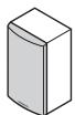
Front Speakers (SKF-570 L/R)
Center Speaker (SKC-570)
Surround Speakers (SKR-570 L/R)
Surround Back Speakers (SKB-570 L/R)
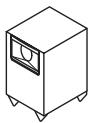
Subwoofer (SKW-570)
Dock for iPod (UP-A1L)
Instruction Manual
Thank you for purchasing an Onkyo 7.1ch Home Theater System. Please read this manual thoroughly before making connections and plugging in the unit. Following the instructions in this manual will enable you to obtain optimum performance and listening enjoyment from your new 7.1ch Home Theater System.
Please retain this manual for future reference.
Contents
Introduction 2
Connections 18
Turning On & First Time Setup.....38
Basic Operations. 44
Using the Listening Modes 64
Advanced Setup 70
Controlling Other Components....78
Others. 84
WARNING:
TO REDUCE THE RISK OF FIRE OR ELECTRIC SHOCK, DO NOT EXPOSE THIS APPARATUS TO RAIN OR MOISTURE.
CAUTION:
TO REDUCE THE RISK OF ELECTRIC SHOCK, DO NOT REMOVE COVER (OR BACK). NO USER-SERVICEABLE PARTS INSIDE. REFER SERVICING TO QUALIFIED SERVICE PERSONNEL.

WARNING
RISK OF ELECTRIC SHOCK
DO NOT OPEN
AVIS
BISQUE DE CHOC ELECTRIQUE
NE PAS OUVRIR


The lightning flash with arrowhead symbol, within an equilateral triangle, is intended to alert the user to the presence of uninsulated "dangerous voltage" within the product's enclosure that may be of sufficient magnitude to constitute a risk of electric shock to persons.

The exclamation point within an equilateral triangle is intended to alert the user to the presence of important operating and maintenance (servicing) instructions in the literature accompanying the appliance.
Important Safety Instructions
-
Read these instructions.
-
Keep these instructions.
-
Heed all warnings.
-
Follow all instructions.
-
Do not use this apparatus near water.
-
Clean only with dry cloth.
-
Do not block any ventilation openings. Install in accordance with the manufacturer's instructions.
-
Do not install near any heat sources such as radiators, heat registers, stoves, or other apparatus (including amplifiers) that produce heat.
-
Do not defeat the safety purpose of the polarized or grounding-type plug. A polarized plug has two blades with one wider than the other. A grounding type plug has two blades and a third grounding prong. The wide blade or the third prong are provided for your safety. If the provided plug does not fit into your outlet, consult an electrician for replacement of the obsolete outlet.
-
Protect the power cord from being walked on or pinched particularly at plugs, convenience receptacles, and the point where they exit from the apparatus.
-
Only use attachments/accessories specified by the manufacturer.
-
Use only with the cart, stand, tripod, bracket, or table specified by the manufacturer, or sold with the apparatus. When a cart is used, use caution when moving the cart/ apparatus combination to avoid injury from tip-over.

PORTABLE CART WARNING
-
Unplug this apparatus during lightning storms or when unused for long periods of time.
-
Refer all servicing to qualified service personnel. Servicing is required when the apparatus has been damaged in any way, such as power-supply cord or plug is damaged, liquid has been spilled or objects have fallen into the apparatus, the apparatus has been exposed to rain or moisture, does not operate normally, or has been dropped.
-
Damage Requiring Service
Unplug the apparatus from the wall outlet and refer servicing to qualified service personnel under the following conditions:
A. When the power-supply cord or plug is damaged,
B. If liquid has been spilled, or objects have fallen into the apparatus,
C. If the apparatus has been exposed to rain or water,
D. If the apparatus does not operate normally by following the operating instructions. Adjust only those controls that are covered by the operating instructions as an improper adjustment of other controls may result in damage and will often require extensive work by a qualified technician to restore the apparatus to its normal operation,
E. If the apparatus has been dropped or damaged in any way, and
F. When the apparatus exhibits a distinct change in performance this indicates a need for service.
- Object and Liquid Entry
Never push objects of any kind into the apparatus through openings as they may touch dangerous voltage points or short-out parts that could result in a fire or electric shock.
The apparatus shall not be exposed to dripping or splashing and no objects filled with liquids, such as vases shall be placed on the apparatus.
Don't put candles or other burning objects on top of this unit.
- Batteries
Always consider the environmental issues and follow local regulations when disposing of batteries.
- If you install the apparatus in a built-in installation, such as a bookcase or rack, ensure that there is adequate ventilation.
Leave 20cm (8") of free space at the top and sides and 10cm (4") at the rear. The rear edge of the shelf or board above the apparatus shall be set 10cm (4") away from the rear panel or wall, creating a flue-like gap for warm air to escape.
-
Recording Copyright—Unless it's for personal use only, recording copyrighted material is illegal without the permission of the copyright holder.
-
AC Fuse—The AC fuse inside the unit is not user-serviceable. If you cannot turn on the unit, contact your Onkyo dealer.
-
Care—Occasionally you should dust the unit all over with a soft cloth. For stubborn stains, use a soft cloth dampened with a weak solution of mild detergent and water. Dry the unit immediately afterwards with a clean cloth. Don't use abrasive cloths, thinners, alcohol, or other chemical solvents, because they may damage the finish or remove the panel lettering.
4. Power Warning
BEFORE PLugging IN THE UNIT FOR THE FIRST TIME, READ THE FOLLOWING SECTION CAREFULLY.
AC outlet voltages vary from country to country. Make sure that the voltage in your area meets the voltage requirements printed on the unit's rear panel (e.g., AC 230 V, 50 Hz or AC 120 V, 60 Hz).
The power cord plug is used to disconnect this unit from the AC power source. Make sure that the plug is readily operable (easily accessible) at all times.
For North American model
Pressing the [ON/STANDBY] button to select Standby mode does not fully shutdown the unit. If you do not intend to use the unit for an extended period, remove the power cord from the AC outlet.
5. Preventing Hearing Loss Caution
Excessive sound pressure from earphones and headphones can cause hearing loss.
6. Batteries and Heat Exposure Warning
Batteries (battery pack or batteries installed) shall not be exposed to excessive heat as sunshine, fire or the like.
- Never Touch this Unit with Wet Hands—Never handle this unit or its power cord while your hands are wet or damp. If water or any other liquid gets inside this unit, have it checked by your Onkyo dealer.
8. Handling Notes
- If you need to transport this unit, use the original packaging to pack it how it was when you originally bought it.
- Do not leave rubber or plastic items on this unit for a long time, because they may leave marks on the case.
- This unit's top and rear panels may get warm after prolonged use. This is normal.
- If you do not use this unit for a long time, it may not work properly the next time you turn it on, so be sure to use it occasionally.
For U.S. models
FCC Information for User
CAUTION:
The user changes or modifications not expressly approved by the party responsible for compliance could void the user's authority to operate the equipment.
NOTE:
This equipment has been tested and found to comply with the limits for a Class B digital device, pursuant to Part 15 of the FCC Rules. These limits are designed to provide reasonable protection against harmful interference in a residential installation.
This equipment generates, uses and can radiate radio frequency energy and, if not installed and used in accordance with the instructions, may cause harmful interference to radio communications. However, there is no guarantee that interference will not occur in a particular installation. If this equipment does cause harmful interference to radio or television reception, which can be determined by turning the equipment off and on, the user is encouraged to try to correct the interference by one or more of the following measures:
- Reorient or relocate the receiving antenna.
- Increase the separation between the equipment and receiver.
- Connect the equipment into an outlet on a circuit different from that to which the receiver is connected.
- Consult the dealer or an experienced radio/TV technician for help.
For Canadian Models
NOTE: THIS CLASS B DIGITAL APPARATUS COMPLIES WITH CANADIAN ICES-003.
For models having a power cord with a polarized plug: CAUTION: TO PREVENT ELECTRIC SHOCK, MATCH WIDE BLADE OF PLUG TO WIDE SLOT, FULLY INSERT.
- The subwoofer cabinet is made out of wood and is therefore sensitive to extreme temperatures and humidity, do not put it in locations subject to direct sunlight or in humid places, such as near an air conditioner, humidifier, bathroom, or kitchen.
- Do not put water or other liquids close to the speakers. If liquid is spilled over the speakers, the drive units may be damaged.
- Speakers should only be placed on sturdy, flat surfaces that are free from vibration. Putting them on uneven or unstable surfaces, where they may fall and cause damage, will affect the sound quality.
- Subwoofer is designed to be used in the upright vertical position only. Do not use it in the horizontal or tilted position.
- If the unit is used near a turntable, CD player or DVD player, howling or slipping of sound may occur. To prevent this, move the unit away from the turntable, CD player or DVD player, otherwise lower the unit's output level.
Using Close to a TV or Computer
TVs and computer monitors are magnetically sensitive devices and as such are likely to suffer discoloration or picture distortion when conventional speakers are placed nearby. To prevent this, the SKF-570 and SKC-570 feature internal magnetic shielding. In some situations, however, discoloration may still be an issue, in which case you should turn off your TV or monitor, wait 15 to 30 minutes, and then turn it back on again. This normally activates the degaussing function, which neutralizes the magnetic field, thereby removing any discoloration effects. If discoloration problems persist, try moving the speakers away from your TV or monitor. Note that discoloration can also be caused by a magnet or demagnetizing tool that's too close to your TV or monitor. Do not place SKR-570 and SKB-570 close to TV or a computer monitor because they have no magnetic shield.
Input Signal Warning
The speakers can handle the specified input power when used for normal music reproduction. If any of the following signals are fed to them, even if the input power is within the specified rating, excessive current may flow in the speaker coils, causing burning or wire breakage:
- Interstation noise from an untuned FM radio.
- Sound from fast-forwarding a cassette tape.
- High-pitched sounds generated by an oscillator, electronic musical instrument, and so on.
- Amplifier oscillation.
- Special test tones from audio test CDs and so on.
- Thumps and clicks caused by connecting or disconnecting audio cables (Always turn off your amplifier before connecting or disconnecting cables.)
- Microphone feedback.
Package Contents
Make sure you have the following accessories:
AV receiver HT-R570
HT-R570
Remote controller and two batteries (AA/R6)
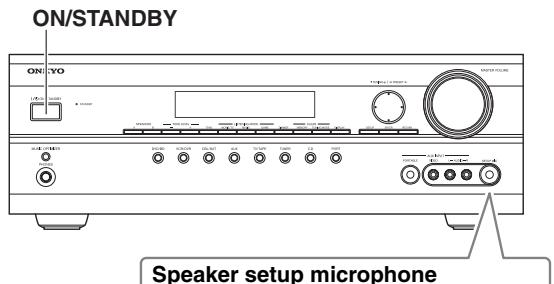
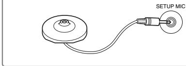
Speaker setup microphone
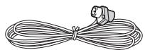
Indoor FM antenna
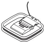
AM loop antenna
Speaker Package HTP-570
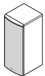
Front speakers (SKF-570 L/R)
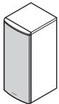
Center speaker (SKC-570)
Surround speakers (SKR-570 L/R)
Surround back speakers (SKB-570 L/R)
Subwoofer (SKW-570)
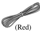


Speaker cable for front speakers and center speaker
Front speakers 11 ft (3.5 m)
Center speaker 10 ft (3.0 m)
(Blue)
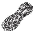
(Gray)
(Brown)
(Tan)
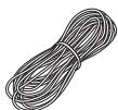
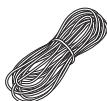
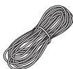
Speaker cables for surround and surround back speakers 26 ft. (8 m)
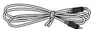
RCA cable for subwoofer connection 10 ft. (3 m)


4 floor pads for the subwoofer

4 rubber spacers for center speaker
Dock for iPod UP-A1L
- In catalogs and on packaging, the letter at the end of the product name indicates the color. Specifications and operation are the same regardless of color.
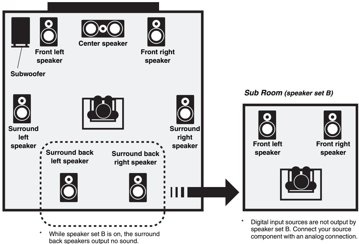
Speaker Sets A and B
You can use two sets of speakers with the AV receiver: speaker set A and speaker set B .
Speaker set A should be used in your main listening room for up to 7.1-channel playback.
- While speaker set B is on, speaker set A is reduced to 5.1-channel playback.
Speaker set B can be used in another room and offers 2-channel stereo playback. - Only analog input sources are output by speaker set B.
or

| Speaker set A | Speaker set B | Indicator | Output |
| On | On | A B | Set A: 5.1 channels Set B: 2 channels |
| Off | A | Set A: 7.1 channels | |
| Off | On | B | Set B: 2 channels |
| Off | No sound |
Main Room (speaker set A)
AV Receiver HT-R570
Amplifier
- 75 Watts/Channel @ 8 ohms (FTC)
130 Watts/Channel @ 6 ohms (IEC) - WRAT-Wide Range Amplifier Technology
High-Current Low-Impedance Drive - Optimum Gain Volume Circuitry
H.C.P.S. (High Current Power Supply) Massive High Power Transformer
Processing
- Dolby Digital EX and Pro Logic IIx*1
- DTS and DTS-ES, DTS 96/24 and DTS Neo:6*2
- Direct Mode
- Music Optimizer ^3 for Compressed Music
- CinemaFILTER
Non-Scaling Configuration - A-Form Listening Mode Memory
24-bit/192kHz D/A Converters - Powerful and Highly Accurate 32-bit DSP Processing
Connections
- 4 HDMI^*4 Inputs and 1 Output (Pass-Thru)
- Component Video Switching (2 Inputs/1 Output)
- 4 Digital Inputs (2 Optical/2 Coaxial)
- Front "Portable" Input for iPod* and MP3 Players
- Speaker A/B Terminal
- Banana Plug-Compatible Speaker Posts
- Subwoofer Pre Out
Color-Coded Speaker Terminals
Miscellaneous
40 AM/FM/SIRIUS5 Presets
Audyssey 2EQ*6 to Correct Room Acoustic Problems
Audyssey Dynamic EQ*6 for Loudness Correction
Audyssey Dynamic Volume*6 to Maintain Optimal Listening Level and Dynamic Range
Crossover Adjustment (40/50/60/80/100/120/150/200Hz)
A/V Sync Control (up to 100ms in 20~ms Steps)
- Theater Dimensional Virtual Surround Function 7
Full-Function RI Remote Control
Speaker Package HTP-570
SKF-570 L/R 2-Way Front Speakers
- 12 cm( 5^ ) OMF cone woofer
- 2.5cm (1") Balanced dome tweeter
Max. input power:130 W - Magnetically shielded
- 6-ohm impedance
Color-coded speaker terminals and speaker cable
SKC-570 2-Way Center Speaker
- 8cm (3-1/4") cone woofer × 2
- 2.5 ~cm (1") Balanced dome tweeter
Max. input power:130 W - Magnetically shielded
- 6-ohm impedance
Color-coded speaker terminals and speaker cable
SKR-570 L/R Full-Range Surround Speakers SKB-570 L/R Full-Range Surround Back Speakers
- 8cm (3-1/4") cone
Max. input power:130 W - 6-ohm impedance
Color-coded speaker terminals and speaker cable
SKW-570 Bass Reflex Powered Subwoofer
- 25cm(10^ ) cone woofer
Max. power:290 W
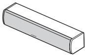
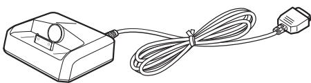
Dock for iPod UP-A1L
- Easily links iPod Touch (1G, 2G), iPod Classic, iPod (4G, 5G), iPod nano (1G, 2G, 3G, 4G), iPod mini with Onkyo A/V Systems
*1 DOLBY
DIGITAL EX PRO LOGIC IIx
Manufactured under license from Dolby Laboratories. "Dolby", "Pro Logic" and the double-D symbol are trademarks of Dolby Laboratories.
\*2 dts
Digital Surround ES Neo:6 96/24
Manufactured under license under U.S. Patent #s: 5,451,942; 5,956,674; 5,974,380; 5,978,762; 6,226,616; 6,487,535; 7,003,467; 7,212,872 & other U.S. and worldwide patents issued & pending. DTS, DTS Digital Surround, ES, and Neo:6 are registered trademarks and the DTS logos, Symbol and DTS 96/24 are trademarks of DTS, Inc. ©1996-2008 DTS, Inc. All Rights Reserved.
*3 Music Optimizer™ is a trademark of Onkyo Corporation.
^*4 HDMI
HDMI, the HDMI logo and High Definition Multimedia Interface are trademarks or registered trademarks of HDMI Licensing, LLC.
*5 SIRIUS
SIRIUS, XM and all related marks and logos are trademarks of Sirius XM Radio Inc. and its subsidiaries. All other marks and logos are the property of their respective owners. All rights reserved. SIRIUS subscription sold separately. Taxes and a one-time activation fee may apply. SIRIUS tune required (sold separately) to receive the SIRIUS service. All programming and fees subject to change. It is prohibited to copy, decompile, disassemble, reverse engineer, hack, manipulate or otherwise make available any technology or software incorporated in receivers compatible with the SIRIUS Satellite Radio System. Service not available in Alaska or Hawaii.
AUDYSSEY ZEQ DYNAMIC EO DYNAMIC VOLUME
Manufactured under license from Audyssey Laboratories. U.S. and foreign patents pending. Audyssey 2EQ^TM Audyssey Dynamic VolumeTM and Audyssey Dynamic EQTM are trademarks of Audyssey Laboratories.
*7 □□ Theater-Dimer
Theater-Dimensional is a trademark of Onkyo Corporation.
- iPod is a trademark of Apple Inc., registered in the U.S. and other countries.
Introduction
Important Safety Instructions 2
Precautions 3
Speaker Precautions 4
Package Contents 4
AV receiver HT-R570 4
Speaker Package HTP-570. 5
Dock for iPod UP-A1L 5
Using Two Sets of Speakers 6
Speaker Sets A and B 6
Features 7
AV Receiver HT-R570 7
Speaker Package HTP-570. 7
Dock for iPod UP-A1L 7
Front & Rear Panels 10
Front Panel. 10
Display 11
Rear Panel 12
Speaker Package 14
Subwoofer (SKW-570) 14
Front, Center, Surround, Surround Back speakers (SKF-570, SKC-570, SKR-570, SKB-570)...... 15
Remote Controller 16
Controlling the AV receiver. 16
Installing the Batteries 17
Aiming the Remote Controller 17
Connections
Connecting the AV receiver 18
Enjoying Home Theater. 18
Connecting Speaker Set A 20
Connecting Speaker Set B 20
Wall Mounting. 21
Using the Rubber Stoppers for a More Stable Platform 21
Using the Floor Pads for Subwoofer 21
Connecting Antenna 22
About AV Connections 24
Connecting Audio and Video Signals to the AV receiver 25
Which Connections Should I Use? 25
Connecting Components with HDMI 26
Making HDMI Connections 27
Connecting a TV or Projector 28
Connecting a DVD/BD player 29
Connecting a VCR or DVR for Playback 30
Connecting a VCR or DVR for Recording 31
Connecting a Satellite, Cable, Terrestrial Set-top box, or Other Video Source 32
Connecting a Camcorder, Game Console, or Other Device 33
Connecting a Portable Audio player 33
Connecting a CD Player or Turntable 34
Connecting a Cassette, CDR, MiniDisc, or DAT Recorder 35
Connecting an RI Dock 36
Connecting the Supplied UP-A1L Dock 36
Connecting Onkyo RI Components 37
Connecting the Power Cord 37
Turning On & First Time Setup
Turning On the AV receiver 38
Turning On and Standby 38
First Time Setup 39
Audyssey 2EQTM Room Correction and Speaker Setup. 39
Component Video Input Setup 42
Digital Input Setup 42
Changing the Input Display 43
Basic Operations
Basic Operations 44
Basic AV receiver Operation 44
Setting the Display Brightness 45
Muting the AV receiver 45
Using the Sleep Timer 45
Using Headphones 46
Adjusting the Bass & Treble 46
Displaying Source Information 46
Using the Music Optimizer 47
Specifying the Digital Signal Format. 47
Listening to the Radio 48
AM/FM Frequency Step Setup 48
Listening to AM/FM Stations. 49
Presetting AM/FM Stations. 51
Listening to SIRIUS Satellite Radio 52
Listening to Satellite Radio 52
Setting the Satellite Radio Mode 53
Selecting SIRIUS Satellite Radio. 53
Signing Up for SIRIUS Satellite Radio. 53
Selecting SIRIUS Satellite Radio Channels 54
Displaying SIRIUS Satellite Radio Information 57
Positioning the SiriusConnect Home Tuner.....57
Parental Lock. 58
Changing the PIN Number 59
UP-A1L Dock for iPod 60
About the UP-A1L Dock 60
Compatible iPod models.. 60
Putting Your iPod in the Dock. 60
Function Overview 60
Controlling iPod 61
Recording 63
Using the Listening Modes
Using the Listening Modes 64
Selecting the Listening Modes.. 64
Listening Modes Available for Each Source Format 65
About the Listening Modes 68
Advanced Setup
Advanced Setup. 70
Common Procedures in Setup Menu 70
Speaker Settings 70
Audio Adjust Settings 73
Hardware Setup. 75
Using the Audio Settings 76
Controlling Other Components
Controlling Other Components 78
Preprogrammed Remote Control Codes 78
Entering Remote Control Codes. 78
Resetting the Remote Controller 79
Controlling a DVD Player, or DVD Recorder 80
Controlling a CD Player, CD Recorder, or MD Player 81
Controlling a Cassette Recorder 82
Controlling an RI Dock. 83
Others
Troubleshooting 84
Specifications 88
Front Panel
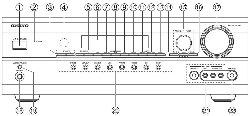
The actual front panel has various logos printed on it. They are not shown here for clarity.
The page numbers in parentheses show where you can find the main explanation for each item.
① ON/STANDBY button (38)
Sets the AV receiver to On or Standby.
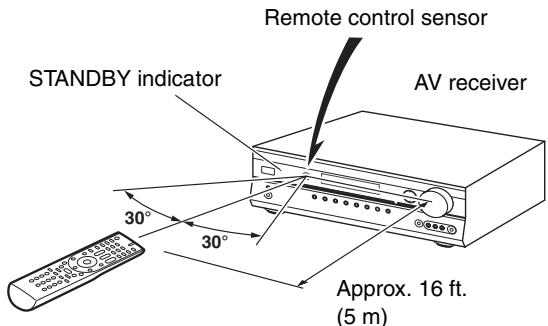
② STANDBY indicator (38)
Lights up when the AV receiver is on Standby and flashes while a signal is being received from the remote controller.
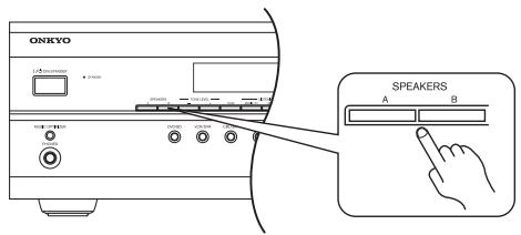
③ SPEAKERS A & B buttons (18, 44)
Turn speaker sets A and B on or off.
④ Remote control sensor (17)
This sensor receives control signals from the remote controller.
⑤ -, + and TONE buttons (46)
Used to adjust the tone (bass and treble).
⑥ Display
See "Display" on page 11.
⑦ MOVIE/TV button (64)
Selects the listening modes intended for use with movies and TV.
MUSIC button (64)
Selects the listening modes intended for use with music.
⑨ GAME button (64)
Selects the listening modes intended for use with video games.
DIMMER button (45)
Adjusts the display brightness.
① MEMORY button (51)
Used when storing or deleting radio presets.
TUNING MODE button (49)
Selects the Auto or Manual tuning mode for AM and FM radio.
DISPLAY button (46, 50)
Displays various information about the currently selected input source.
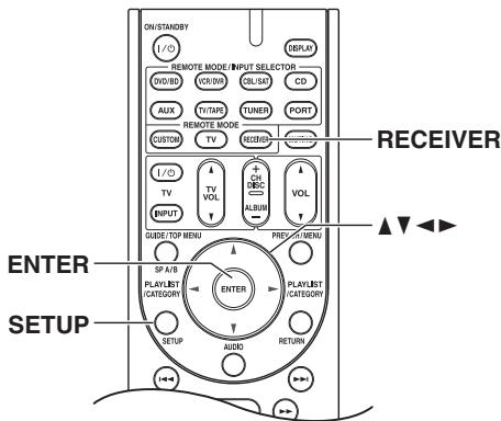
⑭ SETUP button
Opens and closes the setup menus.
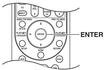
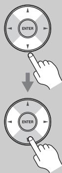
TUNING, PRESET, Arrow, and ENTER buttons
When AM or FM is selected, the TUNING [] / [] buttons are used for radio tuning, and the PRESET [] / [] buttons are used to select radio presets (see page 51). With the setup menus, they work as arrow buttons and are used to select and set items. The [ENTER] button is also used with the setup menus.
For detailed information, see the pages in parentheses.
16 RETURN button
Selects the previously displayed setup menu.
17 MASTER VOLUME control (44)
Sets the volume of the AV receiver to Min, 1 through 79, or Max.
18 PHONES jack (46)
This 1/4-inch phone jack is for connecting a standard pair of stereo headphones for private listening.
19 MUSIC OPTIMIZER button (47, 77)
Turns the Music Optimizer on or off.
Input selector buttons (44)
Select the following input sources: DVD/BD, VCR/DVR, CBL/SAT, AUX, TV/TAPE, TUNER, CD, PORT.
② AUX INPUT (33, 63)
Used to connect a camcorder, game console, and so on. There are input jacks for composite video and analog audio.
PORTABLE (33):
Used to connect a portable Audio Player.
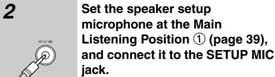
2 SETUP MIC (40)
The Audyssey 2EQ Room Correction and Speaker Setup microphone connects here.
Display
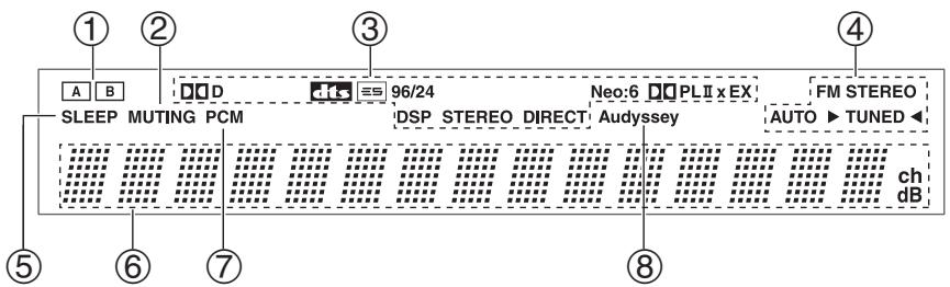
For detailed information, see the pages in parentheses.
① A and B speaker indicators (18, 44)
Indicator A lights up when speaker set A is on.
Indicator B lights up when speaker set B is on.
② MUTING indicator (45)
Flashes while the AV receiver is muted.
③ Listening mode and format indicators (64)
Show the selected listening mode and audio input signal format.
④ Tuning indicators (49)
FM STEREO (49):
Lights up when tuned to a stereo FM station.
AUTO (49):
Lights up when Auto Tuning mode is selected for AM or FM radio. Goes off when Manual Tuning mode is selected.
TUNED (49):
Lights up when tuned to a radio station.
⑤ SLEEP indicator (45)
Lights up when the Sleep function has been set.
⑥ Message area
Displays various information.
⑦ Audio input indicators
Indicate the type of audio input that's selected as the audio source: PCM.
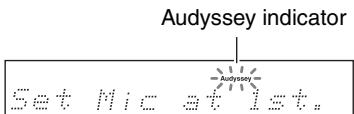
⑧ Audyssey indicator (40)
Flashes during Audyssey 2EQ^TM Room Correction and Speaker Setup. Lights up when the "Equalizer Settings" is set to "Audyssey".
Rear Panel
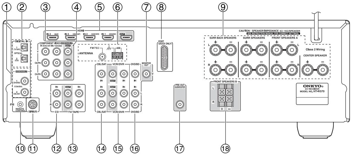
① DIGITAL IN COAXIAL 1 and 2
These coaxial digital audio inputs are for connecting components with a coaxial digital audio output, such as a CD player or DVD/BD player. They're assignable, which means you can assign each one to an input selector to suit your setup. See "Digital Input Setup" on page 42.
② DIGITAL IN OPTICAL 1 and 2
These optical digital audio inputs are for connecting components with an optical digital audio output, such as a CD player or DVD/BD player. They're assignable, which means you can assign each one to an input selector to suit your setup. See "Digital Input Setup" on page 42.
(3) COMPONENT VIDEO IN 1 and 2
These RCA component video inputs are for connecting components with a component video output, such as a DVD/BD player, DVD/BD recorder, or DVR (digital video recorder). They're assignable, which means you can assign each one to an input selector to suit your setup. See "Component Video Input Setup" on page 42.
(4) COMPONENTVIDEO OUT
This RCA component video output is for connecting a TV or projector with a component video input.
(5) HDMI IN 1-4 and OUT
HDMI (High Definition Multimedia Interface) connections carry digital audio and digital video. The HDMI inputs are for connecting components with an HDMI output, such as a DVD/BD player, DVD/BD recorder, or DVR (digital video recorder). The HDMI outputs are for connecting a TV or projector with an HDMI input.
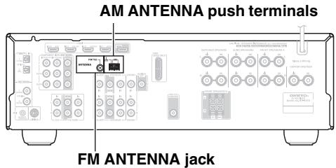
⑥ AM and FM ANTENNA
The AM push terminals are for connecting an AM antenna. The FM jack is for connecting an FM antenna.
⑦ MONITOR OUT
The composite video jack should be connected to a video input on your TV or projector.
⑧ PORT
This jack is for connecting the supplied UP-A1L Dock.
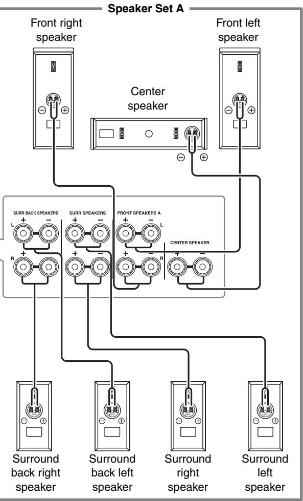
9 FRONT L/R, CENTER, SURR L/R, and SURR BACK L/R SPEAKERS
These terminal posts are for connecting the front speakers, center, surround, and surround back speakers.
10 RI REMOTE CONTROL
This RI (Remote Interactive) jack can be connected to the RI jack on another RI-capable Onkyo component for remote and system control. To use RI, you must make an analog audio connection (RCA) between the AV receiver and the other component, even if they are connected digitally.
SIRIUS
This jack is for connecting the SiriusConnect receiver (not supplied).
CD IN
This analog audio input is for connecting a CD player's analog audio output.
⑤ TV/TAPE IN/OUT
These analog audio input and output jacks are for connecting a recorder with an analog audio input and output, such as a cassette deck, MD recorder, etc.
14 CBL/SAT IN
A cable or satellite receiver can be connected here. There is composite video input jacks for connecting the video signal, and there are analog audio input jacks for connecting the audio signal.
15 VCR/DVR IN/OUT
A video component, such as a VCR or DVR, can be connected here for recording and playback. There is composite video input and output jacks for connecting the video signal, and there are analog audio input jacks for connecting the audio signal.
16 DVD/BD IN
This input is for connecting a DVD/BD player. There is composite video input jacks for connecting the video signal, and there are analog audio input jacks for connecting the audio signal.
17 SUBWOOFER PRE OUT
This analog audio output can be connected to a powered subwoofer.
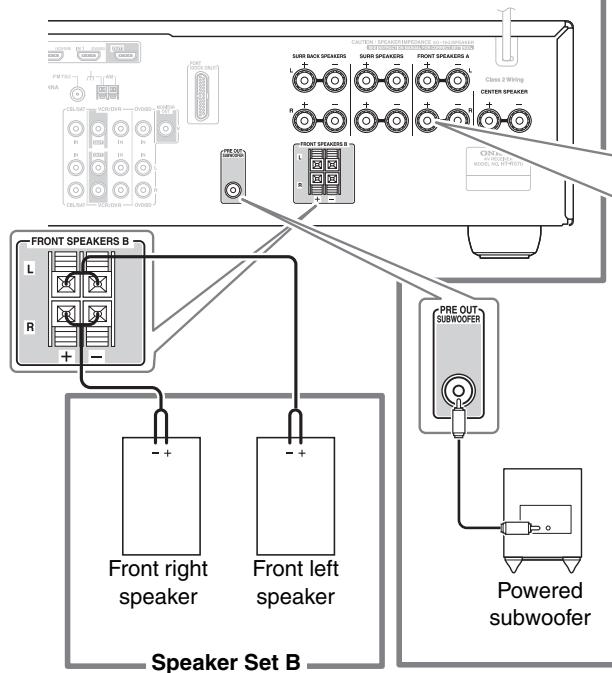
18 FRONT SPEAKERS B
These push terminals are for connecting speaker set B.
Subwoofer (SKW-570)
For detailed information, see the pages in parentheses.
■Front
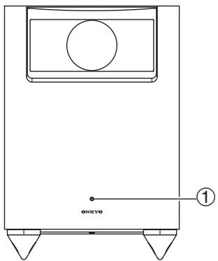
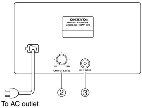
Rear
① STANDBY/ON indicator
Red: Subwoofer in standby mode
Blue: Subwoofer on
With the Auto Standby function, the SKW-570 automatically turns on when an input signal is detected in Standby mode. When there's no input signal for a while, the SKW-570 automatically enters Standby mode.
② OUTPUT LEVEL control (44)
This control is used to adjust the volume of the subwoofer.
③ LINE INPUT (20)
This RCA input should be connected to the subwoofer pre out on the AV receiver with supplied RCA cable.
Note:
The Auto Standby function turns the subwoofer on when the input signal exceeds a certain level. If the Auto Standby function does not work reliably, try slightly increasing or decreasing the subwoofer output level on the AV receiver (page 72).
Front, Center, Surround, Surround Back speakers (SKF-570, SKC-570, SKR-570, SKB-570)
Rear

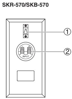
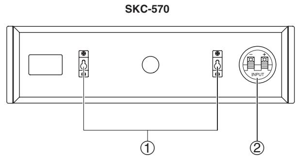
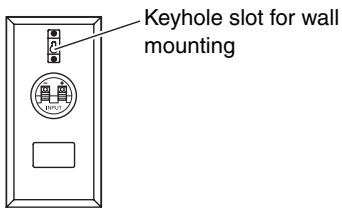
① Keyhole slots
These keyhole slots can be used to wall-mount the speaker. See page 21 for mounting instructions.
② Speaker terminals
These push terminals are for connecting the speaker to the HT-R570 with the supplied speaker cables. The supplied speaker cables are color-coded for easy identification. Simply connect each cable to the same-colored positive speaker terminal.
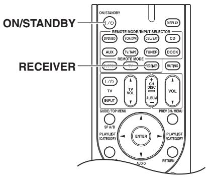
Controlling the AV receiver
To control the AV receiver, press the [RECEIVER] button to select Receiver mode.
You can also use the remote controller to control your DVD/BD player, CD player, and other components. See page 78 for more details.
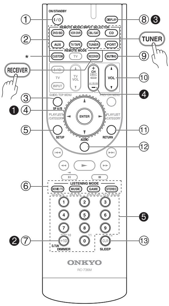
For detailed information, see the pages in parentheses.
① ON/STANDBY button (38)
Sets the AV receiver to On or Standby.
② REMOTE MODE/INPUT SELECTOR buttons (44, 61, 80-83)
Selects the remote controller modes and the input sources.
③ SP A/B button (18, 44)
This button is used to turn speaker sets A and B on or off.
④ Arrow [▲]/[▼]/[▲]/[▶] and ENTER buttons
Used to select and adjust settings.
⑤ SETUP button
Used to change settings.
⑥ LISTENING MODE buttons (64)
Used to select the listening modes.
⑦ DIMMER button (45)
Adjusts the display brightness.
⑧ DISPLAY button (46)
Displays information about the current input source.
⑨ MUTING button (45)
Mutes or unmutes the AV receiver.
10 VOL [ ] / [ ] button (44)
Adjusts the volume of the AV receiver regardless of the currently selected remote controller mode.
RETURN button
Returns to the previous display when changing settings.
⑫ AUDIO button (47, 76)
Used to change audio settings.
SLEEP button (45)
Used with the Sleep function.
Controlling the tuner
To control the AV receiver's tune, press the [TUNER] (or [RECEIVER]) button.
You can select AM or FM by pressing the [TUNER] button repeatedly.
Arrow [ ] / [ ] buttons
Used to tune into radio stations.
D.TUN button (50)
Selects the Direct tuning mode.
③ DISPLAY button (50)
Displays information about the band, frequency, preset number, and so on.
CH + / - button (51)
Selects radio presets.
Number buttons (50)
Used to select AM and FM radio stations directly (In the Direct tuning mode).
- To control component, you must first enter remote control code.
For details on entering a remote control code for a different component, see page 78.
Note:
An Onkyo cassette recorder connected via RI can also be controlled in Receiver mode (see page 82).
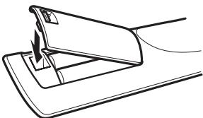
Installing the Batteries
1 To open the battery compartment, press the small lever and remove the cover.
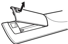
2 Insert the two supplied batteries (AA/R6) in accordance with the polarity diagram inside the battery compartment.
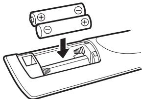
3 Replace the cover and push it shut.
Notes:
- If the remote controller doesn't work reliably, try replacing the batteries.
- Don't mix new and old batteries or different types of batteries.
- If you intend not to use the remote controller for a long time, remove the batteries to prevent damage from leakage or corrosion.
- Expired batteries should be removed as soon as possible to prevent damage from leakage or corrosion.
Aiming the Remote Controller
When using the remote controller, point it toward the AV receiver's remote control sensor, as shown below.
Notes:
- The remote controller may not work reliably if the AV receiver is subjected to bright light, such as direct sunlight or inverter-type fluorescent lights. Keep this in mind when installing.
- If another remote controller of the same type is used in the same room, or the AV receiver is installed close to equipment that uses infrared rays, the remote controller may not work reliably.
- Don't put anything on top of the remote controller, such as a book or magazine, because a button may be pressed continuously, thereby draining the batteries.
- The remote controller may not work reliably if the AV receiver is installed in a rack behind colored glass doors. Keep this in mind when installing.
- The remote controller will not work if there's an obstacle between it and the AV receiver's remote control sensor.
Enjoying Home Theater
Thanks to the AV receiver's superb capabilities, you can enjoy surround sound with a real sense of movement in your own home—just like being in a movie theater or concert hall. You can enjoy DVDs featuring Dolby Digital or DTS. With analog or digital TV, you can enjoy Dolby Pro Logic IIx, DTS Neo:6, or Onkyo's original DSP listening modes.
Front left and right speakers (SKF-570)
These output the main sound. Their role in a home theater is to provide a solid anchor for the sound image. They should be positioned facing the listener at about ear level, and equally spaced from the TV. Angle them inward slightly so as to create a triangle, with the listener at the apex.
Surround left and right speakers (SKR-570)
These speakers are used for precise sound positioning and to add realistic ambience.
Position them at the sides of the listener, or slightly behind, about 2-3 feet (60-100 cm) above ear level. Ideally they should be equally spaced from the listener.
Center speaker (SKC-570)
This speaker enhances the front left and right speakers, making sound movements distinct and providing a full sound image. For movies it's used mainly for dialog.
Position it close to your TV (preferably on top) facing forward at about ear level, or at the same height as the front left and right speakers.
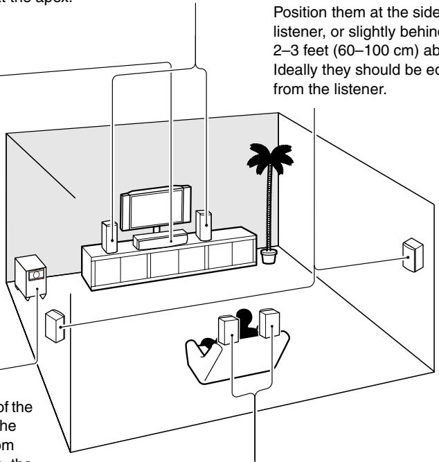
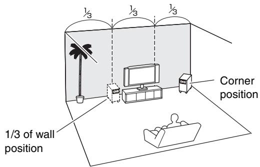
Subwoofer (SKW-570)
The subwoofer handles the bass sounds of the LFE (Low-Frequency Effects) channel. The volume and quality of the bass output from your subwoofer will depend on its position, the shape of your listening room, and your listening position. In general, a good bass sound can be obtained by installing the subwoofer in a front corner, or at one-third the way along the front wall, as shown.
Tip: To find the best position for your subwoofer, while playing a movie or some music with good bass, experiment by placing your subwoofer at various positions within the room and choose the one that provides the most satisfying results.
Surround back left and right speakers (SKB-570)
These speakers are necessary to enjoy Dolby Digital EX, DTS-ES Matrix, DTS-ES Discrete, etc. They enhance the realism of surround sound and improve sound localization behind the listener. Position them behind the listener about 2-3 feet (60-100 cm) above ear level.
Speaker Configuration
For 7.1-channel surround-sound playback, you need seven speakers and a powered subwoofer. The following table shows which channels you should use based on the number of speakers you have.
| Number of speakers: | 2 | 3 | 4 | 5 | 6 | 7 |
| Front left | ✓ | ✓ | ✓ | ✓ | ✓ | ✓ |
| Front right | ✓ | ✓ | ✓ | ✓ | ✓ | ✓ |
| Center | ✓ | ✓ | ✓ | ✓ | ||
| Surround left | ✓ | ✓ | ✓ | ✓ | ||
| Surround right | ✓ | ✓ | ✓ | ✓ | ||
| Surround back* | ✓ | |||||
| Surround back left | ✓ | |||||
| Surround back right | ✓ |
- If you're using only one surround back speaker, connect it to the SURR BACK L terminals.
No matter how many speakers you use, a powered subwoofer is recommended for a powerful and solid bass.
To get the best from your surround-sound system, you must set the speaker settings. You can do this automatically (see page 39) or manually (see page 70).
Speaker Connection Precautions
Read the following before connecting your speakers:
- You can connect speakers with an impedance of between 6 and 16 ohms. If you use speakers with a lower impedance, and use the amplifier at high volume levels for a long period of time, the built-in amp protection circuit may be activated.
- Disconnect the power cord from the wall outlet before making any connections.
- Read the instructions supplied with your speakers.
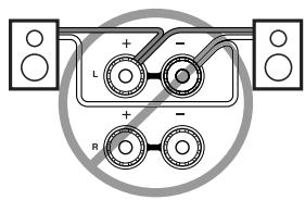
- Pay close attention to speaker wiring polarity. Connect positive (+) terminals to only positive (+) terminals, and negative (-) terminals to only negative (-) terminals. If you get them the wrong way around, the sound will be out of phase and will sound unnatural.
- Unnecessarily long or very thin speaker cables may affect the sound quality and should be avoided.
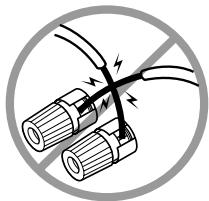
- Be careful not to short the positive and negative wires. Doing so may damage the AV receiver.
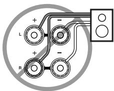
- Don't connect more than one cable to each speaker terminal. Doing so may damage the AV receiver.
- Don't connect a speaker to several terminals.
Connecting Speaker Set A
1
Strip 1 / 2^ - 5 / 8^ (12-15 mm) of insulation from the ends of the speaker cables. (Supplied speaker cables are already stripped.)
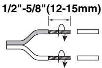
2
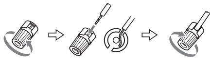
Unscrew the terminal. Fully insert the bare wire, making sure that it's touching the threaded shaft in the center. Screw the terminal tight.
1
Connecting Speaker Set B
Strip 3 / 8^ - 1 / 2^ (10-12 mm) of insulation from the ends of the speaker cables, and twist the bare wires tightly, as shown.
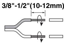
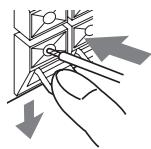
2
While pressing the lever, insert the wire into the hole, and then release the lever.
Make sure that the terminals are gripping the bare wires, not the insulation.
Note:
While speaker set B is on, speaker set A is reduced to 5.1-channel playback.
The following illustration shows which speaker should be connected to each pair of terminals.
If you're using only one surround back speaker, connect it to the left (L) SURR BACK SPEAKERS terminals.
Wall Mounting
The speakers can easily be wall mounted by using the keyhole slots.
To mount the front or surround speakers vertically, use the keyhole slot shown to hang each speaker on a screw that's securely screwed into the wall.
Front speakers (SKF-570)

Surround speakers/Surround back speakers (SKR-570/SKB-570)
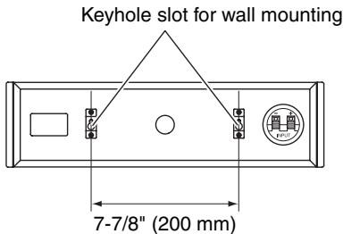
To mount the center speaker horizontally, use the two keyhole slots shown to hang each speaker on two screws that are securely screwed into the wall.
Center speaker (SKC-570)
Caution:
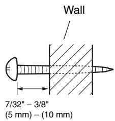
A mounting screw's ability to support a speaker depends on how well it's anchored to the wall. If you have hollow walls, screw each mounting screw into a stud. If there are no studs, or the walls are solid, use suitable wall anchors. Use screws with a head diameter of 5/16'' (8 mm) or less and a shank diameter of 5/32'' (4 mm) or less. With hollow walls, use a cable/pipe detector to check for any power cables or water pipes before making any holes.
Leave a gap of between 7 / 32'' (5 mm) and 3 / 8'' (10 mm) between the wall and the base of the screw head, as shown. (We recommend that you consult a home installation professional.)
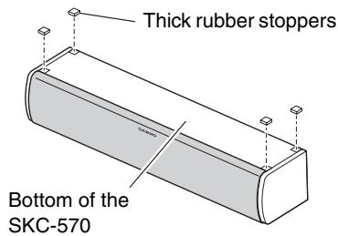
Using the Rubber Stoppers for a More Stable Platform
We recommend using the provided rubber stoppers to achieve the best possible sound from your speakers. The rubber stoppers prevent the speakers from moving, providing a more stable platform. Use thick stoppers for the center speaker.
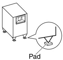
Using the Floor Pads for Subwoofer
If the subwoofer is placed on a hard floor (wood, vinyl, tile, etc.) and playback is very loud, the subwoofer's feet may damage the flooring. To prevent this, place the supplied pads underneath the subwoofer's feet. The pads also provide a stable base for the subwoofer.
Connecting Antenna
This section explains how to connect the supplied indoor FM antenna and AM loop antenna, and how to connect commercially available outdoor FM and AM antennas. The AV receiver won't pick up any radio signals without any antenna connected, so you must connect the antenna to use the tuner.
Connecting the Indoor FM Antenna
The supplied indoor FM antenna is for indoor use only.
1 Attach the FM antenna, as shown.
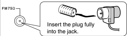
Once your AV receiver is ready for use, you'll need to tune into an FM radio station and adjust the position of the FM antenna to achieve the best possible reception.
2 Use thumbtacks or something similar to fix the FM antenna into position.
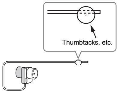
Caution: Be careful that you don't injure yourself when using thumbtacks.
If you cannot achieve good reception with the supplied indoor FM antenna, try a commercially available outdoor FM antenna instead (see page 23).
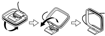
Connecting the AM Loop Antenna
The supplied indoor AM loop antenna is for indoor use only.
1 Assemble the AM loop antenna, inserting the tabs into the base, as shown.
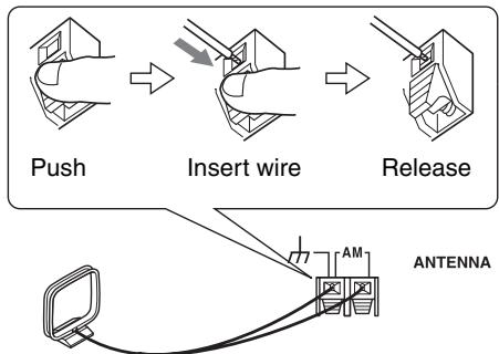
2 Connect both wires of the AM loop antenna to the AM push terminals, as shown.
(The antenna's wires are not polarity sensitive, so they can be connected either way around.)
Make sure that the wires are attached securely and that the push terminals are gripping the bare wires, not the insulation.
Once your AV receiver is ready for use, you'll need to tune into an AM radio station and adjust the position of the AM antenna to achieve the best possible reception.
Keep the antenna as far away as possible from your AV receiver, TV, speaker cables, and power cords.
If you cannot achieve good reception with the supplied indoor AM loop antenna, try using it with a commercially available outdoor AM antenna (see page 23).
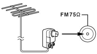
Connecting an Outdoor FM Antenna
If you cannot achieve good reception with the supplied indoor FM antenna, try a commercially available outdoor FM antenna instead.
Notes:
- Outdoor FM antennas work best outside, but usable results can sometimes be obtained when installed in an attic or loft.
- For best results, install the outdoor FM antenna well away from tall buildings, preferably with a clear line of sight to your local FM transmitter.
- Outdoor antenna should be located away from possible noise sources, such as neon signs, busy roads, etc.
- For safety reasons, outdoor antenna should be situated well away from power lines and other high-voltage equipment.
- Outdoor antenna must be grounded in accordance with local regulations to prevent electrical shock hazards.
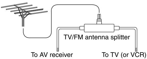
Using a TV/FM Antenna Splitter
It's best not to use the same antenna for both FM and TV reception, as this can cause interference problems. If circumstances demand it, use a TV/FM antenna splitter, as shown.
Connecting an Outdoor AM Antenna
If good reception cannot be achieved using the supplied AM loop antenna, an outdoor AM antenna can be used in addition to the loop antenna, as shown.
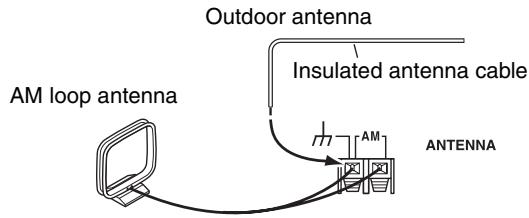
Outdoor AM antennas work best when installed horizontally outside, but good results can sometimes be obtained indoors by mounting horizontally above a window. Note that the AM loop antenna should be left connected.
Outdoor antenna must be grounded in accordance with local regulations to prevent electrical shock hazards.
About AV Connections
- Before making any AV connections, read the manuals supplied with your other AV components.
- Don't connect the power cord until you've completed and double-checked all AV connections.
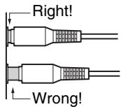
Optical Digital Jacks
The AV receiver's optical digital jacks have shutter-type covers that open when an optical plug is inserted and close when it's removed. Push plugs in all the way.
Caution:
To prevent shutter damage, hold the optical plug straight when inserting and removing.
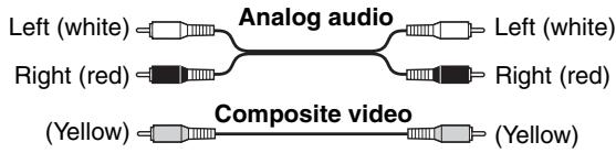
AV Connection Color Coding
RCA-type AV connections are usually color coded: red, white, and yellow. Use red plugs to connect right-channel audio inputs and outputs (typically labeled "R"). Use white plugs to connect left-channel audio inputs and outputs (typically labeled "L"). And use yellow plugs to connect composite video inputs and outputs.
- Push plugs in all the way to make good connections (loose connections can cause noise or malfunctions).
- To prevent interference, keep audio and video cables away from power cords and speaker cables.
AV Cables and Jacks
Video/Audio
| Cable | Jack | Description | |
| HDMI | HDMI | HDMI connections can carry uncompressed standard- or high-definition digital video and audio and offer the best picture and sound quality. | |
Video
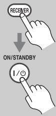
| Component video cable | Y PB/CB PR/CR | Y PB/CB PR/CR | Component video separates the luminance (Y) and color difference signals (PR, PB), providing the best picture quality. (Some TV manufacturers label their component video jacks slightly differently.) |
| Composite video cable | Composite video is commonly used on TVs, VCRs, and other video equipment. |
Audio
| Optical digital audio cable | OPTICAL | This offers the best sound quality and allows you to enjoy Dolby Digital and DTS. The audio quality is the same as for coaxial. | |
| Coaxial digital audio cable | COAXIAL | This offers the best sound quality and allows you to enjoy Dolby Digital and DTS. The audio quality is the same as for optical. | |
| Analog audio cable (RCA) | L R | This cable carries analog audio. It's the most common connection format for analog audio and can be found on virtually all AV components. | |
| Stereo mini plug cable | PORTABLE | This cable carries analog audio. |
Note: The AV receiver does not support SCART connections.
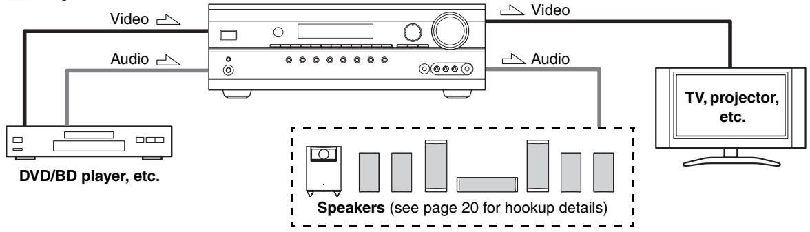
Connecting Audio and Video Signals to the AV receiver
By connecting both the audio and video outputs of your DVD player and other AV components to the AV receiver, you can switch the audio and video signals simultaneously simply by changing the input source on the AV receiver.

: Signal Flow
Which Connections Should I Use?
The AV receiver supports several connection formats for compatibility with a wide range of AV equipment. The format you choose will depend on the formats supported by your other components. Use the following sections as a guide. For video components, you must make an audio connection and a video connection.
Video Connection Formats
Video equipment can be connected to the AV receiver by using any one of the following video connection formats: composite video, component video, or HDMI, the latter offering the best picture quality.
When choosing a connection format, bear in mind that the AV receiver doesn't convert between formats, so only outputs of the same format as the input will output the signal.
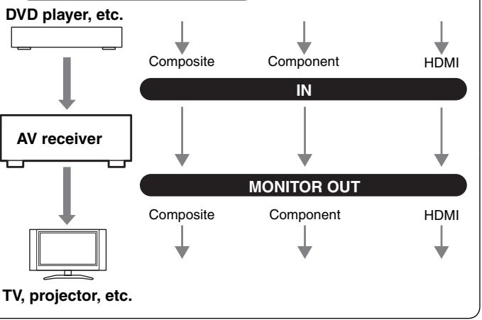
Video Signal Flow Chart
Audio Connection Formats
Audio equipment can be connected to the AV receiver by using any of the following audio connection formats: analog, optical, coaxial, or HDMI.
When you connect audio equipment to an OPTICAL or COAXIAL input, you must assign that input to an input selector (see page 42).
Audio signals received by the HDMI IN jacks are output only by the HDMI OUT (Pass-Thru). HDMI sources are not output by the speakers connected to the AV receiver.
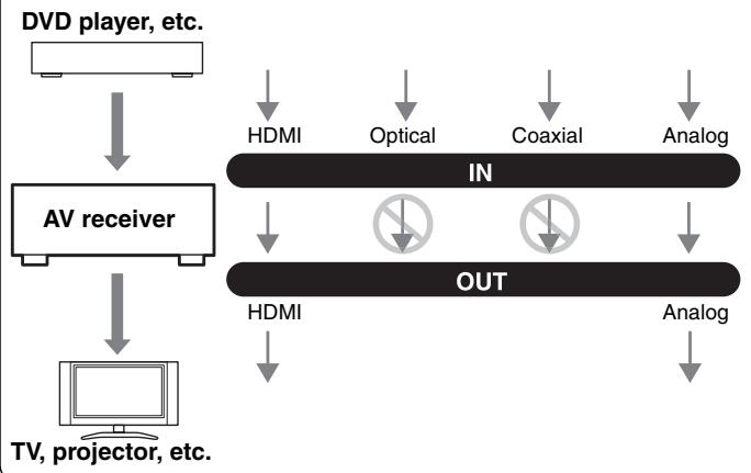
Audio Signal Flow Chart
Connecting Components with HDMI
About HDMI
Designed to meet the increased demands of digital TV, HDMI (High Definition Multimedia Interface) is a new digital interface standard for connecting TVs, projectors, DVD/BD players, set-top boxes, and other video components. Until now, several separate video and audio cables have been required to connect AV components. With HDMI, a single cable can carry control signals, digital video, and up to eight channels of digital audio (2-channel PCM, multichannel digital audio, or multichannel PCM).
The HDMI video stream (i.e., video signal) is compatible with DVI (Digital Visual Interface), ^*1 so TVs and displays with a DVI input can be connected by using an HDMI-to-DVI adapter cable. (This may not work with some TVs and displays, resulting in no picture.)
The AV receiver uses HDCP (High-bandwidth Digital Content Protection), so only HDCP-compatible components will display a picture.
The AV receiver's HDMI interface is based on the following standard:
Pass-Thru
About Copyright Protection
The AV receiver supports HDCP (High-bandwidth Digital Content Protection), ^2 a copy-protection system for digital video signals. Other devices connected to the AV receiver via HDMI must also support HDCP.
Use a commercially available HDMI cable (supplied with some components) to connect the AV receiver's HDMI OUT to the HDMI input on your TV or projector.
1 DVI (Digital Visual Interface): The digital display interface standard set by the DDWG ^3 in 1999.
2 HDCP (High-bandwidth Digital Content Protection): The video encryption technology developed by Intel for HDMI/DVI. It's designed to protect video content and requires a HDCP-compatible device to display the encrypted video.
3 DDWG (Digital Display Working Group): Led by Intel, Compaq, Fujitsu, Hewlett Packard, IBM, NEC, and Silicon Image, this open industry group's objective is to address the industry's requirements for a digital connectivity specification for high-performance PCs and digital displays.
Making HDMI Connections
If you have an HDMI-compatible player, you can connect it to the AV receiver with an HDMI cable.
Step 1: Connect your HDMI-compatible TV to the AV receiver's HDMI OUT jack.
Step 2: Connect your HDMI-compatible player to the AV receiver's HDMI IN 1, 2, or 3 jack.
Step 3: Connect your HDMI-compatible player to an analog and/or digital audio input on the AV receiver.
Audio Signals
- Audio and video signals received via inputs other than the HDMI IN jacks are not output by the HDMI OUT.
- Audio and video signals received via the HDMI IN jacks are output only by the HDMI OUT.
- To watch an HDMI source that's connected via the AV receiver's HDMI jacks, the AV receiver must be turned on, otherwise no HDMI signal will be output.
- If you want to listen through the speakers connected to the AV receiver, in addition to an HDMI connection, you'll also need to make a separate analog or digital audio connection.
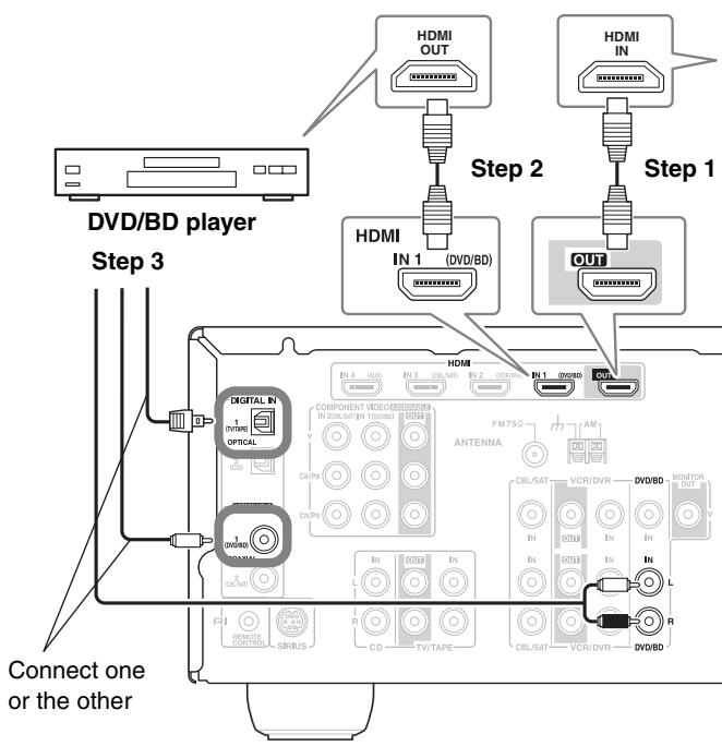
Tip!
If you make the connection described in step 3, to fully enjoy the AV receiver's listening modes, turn down the volume on your TV all the way so that its speakers output no sound.
Sound off
Notes:
- The HDMI video stream is compatible with DVI (Digital Visual Interface), so TVs and displays with a DVI input can be connected by using an HDMI-to-DVI adapter cable. (Note that DVI connections only carry video, so you'll need to make a separate connection for audio.) However, reliable operation with such an adapter is not guaranteed. In addition, video signals from a PC are not supported.
- When listening to an HDMI component through the AV receiver, set the HDMI component so that its video can be seen on the TV screen (on the TV, select the input of the HDMI component connected to the AV receiver).
- The HDMI audio signal (sampling rate, bit length, etc.) may be restricted by the connected source component. If the picture is poor or there's no sound from a component connected via HDMI, check its setup. Refer to the connected component's instruction manual for details.
Connecting a TV or Projector
Step 1: Video Connection
Choose a video connection that matches your TV (A or B), and then make the connection.
Step 2: Audio Connection
Choose an audio connection that matches your TV (a, b, or c), and then make the connection.
- With connection a, you can listen to and record audio from your TV.
To enjoy Dolby Digital and DTS, use connection b or c.
| Connection | AV receiver | Signal flow | TV |
| A | COMPONENT Video OUT | ⇒ | Component video input |
| B | MONITOR OUT V | ⇒ | Composite video input |
| a | TV/TAPE IN L/R | ← | Analog audio L/R output |
| b | DIGITAL IN COAXIAL 1 (DVD/BD) | ← | Digital coaxial output |
| c | DIGITAL IN OPTICAL 1 (TV/TAPE) | ← | Digital optical output |


If your TV has no audio outputs, connect an audio output from your VCR or cable or satellite receiver to the AV receiver and use its tuner to listen to TV programs through the AV receiver (see pages 30 and 32).
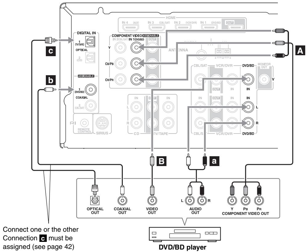
Connecting a DVD/BD player
Step 1: Video Connection
Choose a video connection that matches your DVD/BD player (A or B), and then make the connection.
You must connect the AV receiver to your TV with the same type of connection.
Step 2: Audio Connection
Choose an audio connection that matches your DVD/BD player (a, b, or c), and then make the connection.
- With connection a, you can listen to and record audio from a DVD.
- To enjoy Dolby Digital and DTS, use connection b or c. (To record as well, use a and b, or a and c.)
- If your DVD/BD player has main left and right outputs and multichannel left and right outputs, be sure to use the main left and right outputs for connection a.
| Connection | AV receiver | Signal flow | DVD/BD player |
| A | COMPONENT Video IN 1 (DVD/BD) | ← | Component video output |
| B | DVD/BD IN V | ← | Composite video output |
| a | DVD/BD IN L/R | ← | Analog audio L/R output |
| b | DIGITAL IN COAXIAL 1 (DVD/BD) | ← | Digital coaxial output |
| c | DIGITAL IN OPTICAL 1 (TV/TAPE) | ← | Digital optical output |
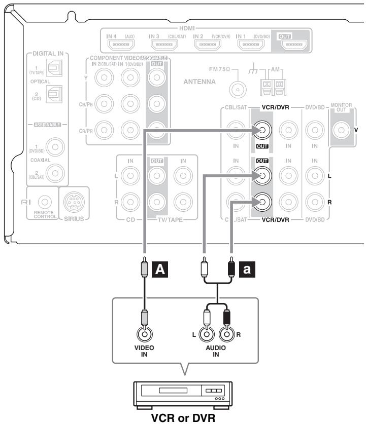
Connecting a VCR or DVR for Playback

With this hookup, you can use the tuner in your VCR or DVR to listen to your favorite TV programs via the AV receiver, which is useful if your TV has no audio outputs.
Step 1: Video Connection
Choose a video connection that matches your VCR or DVR (A or B), and then make the connection. You must connect the AV receiver to your TV with the same type of connection.
Step 2: Audio Connection
Choose an audio connection that matches your VCR or DVR (a, b, or c), and then make the connection.
- To enjoy Dolby Digital and DTS, use connection b or c.
| Connection | AV receiver | Signal flow | VCR or DVR |
| A | COMPONENT Video IN 2 (CBL/SAT) | ← | Component video output |
| B | VCR/DVR IN V | ← | Composite video output |
| a | VCR/DVR IN L/R | ← | Analog audio L/R output |
| b | DIGITAL IN COAXIAL 1 (DVD/BD) | ← | Digital coaxial output |
| c | DIGITAL IN OPTICAL 1 (TV/TAPE) | ← | Digital optical output |

Connecting a VCR or DVR for Recording
Step 1: Video Connection
Make the video connection A.
Step 2: Audio Connection
Make the audio connection a
| Connection | AV receiver | Signal flow | VCR or DVD recorder |
| A | VCR/DVR OUT V | ⇒ | Composite video input |
| a | VCR/DVR OUT L/R | ⇒ | Audio L/R input |
Notes:
- The AV receiver must be turned on for recording. Recording is not possible while it's on Standby.
- If you want to record directly from your TV or another video source without going through the AV receiver, connect the audio and video outputs from your TV or other video component directly to the recording VCR/DVR's audio and video inputs. See the manuals supplied with your TV or VCR/DVR for details.
- Video signals connected to composite video inputs can only be recorded via the VCR/DVR OUT V jack. So if your source TV or VCR is connected to a composite video input, the recording VCR/DVR must be connected to the VCR/DVR OUT V jack.
Connecting a Satellite, Cable, Terrestrial Set-top box, or Other Video Source

With this hookup, you can use your satellite or cable receiver to listen to your favorite TV programs via the AV receiver, which is useful if your TV has no audio outputs.
Step 1: Video Connection
Choose a video connection that matches the video source (A or B), and then make the connection.
You must connect the AV receiver to your TV with the same type of connection.
Step 2: Audio Connection
Choose an audio connection that matches the video source (a, b, or c), and then make the connection.
- With connection a, you can listen to and record audio from the video source.
To enjoy Dolby Digital and DTS, use connection b or c. (To record as well, use a and b, or a and c.)
| Connection | AV receiver | Signal flow | Video source |
| A | COMPONENT Video IN 2 (CBL/SAT) | ← | Component video output |
| B | CBL/SAT IN V | ← | Composite video output |
| a | CBL/SAT IN L/R | ← | Analog audio L/R output |
| b | DIGITAL IN COAXIAL 2 (CBL/SAT) | ← | Digital coaxial output |
| c | DIGITAL IN OPTICAL 1 (TV/TAPE) | ← | Digital optical output |
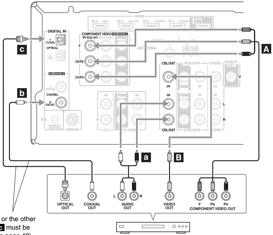
Satellite, cable, set-top box, etc.
Connect one or the other Connection c must be assigned (see page 42)
Connecting a Camcorder, Game Console, or Other Device
Step 1: Make the video connection A.
Step 2: Make the audio connection a.
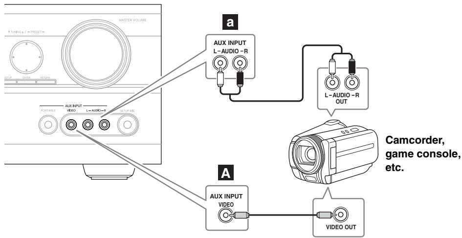
| Connection | AV receiver | Signal flow | Camcorder or console |
| A | AUX INPUT VIDEO | ← | Composite video output |
| a | AUX INPUT L-AUDIO-R | ← | Analog audio L/R output |
Connecting a Portable Audio player
Step 1: Make the audio connection a.
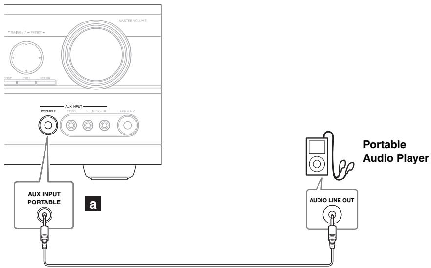
| Connection | AV receiver | Signal flow | Portable Audio Player |
| a | AUX INPUT PORTABLE | ← | Analog audio Line output |
Note:
When it is connected at the same time as AUX INPUT AUDIO L/R terminal, the input of PORTABLE is given priority to and outputted.
Connecting a CD Player or Turntable
CD Player or Turntable (MM) with Built-in Phono Preamp
Step 1:
Choose a connection that matches your CD player (a, b, or c). Use connection a for a turntable with a built-in phono preamp.
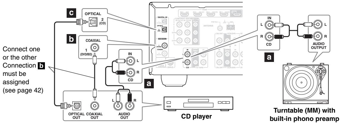
- With connection a, you can listen to and record audio from the CD player.
- To connect the CD player digitally, use connection b or c.
| Connection | AV receiver | Signal flow | CD or turntable |
| a | CD IN L/R | ← | Analog audio L/R output |
| b | DIGITAL IN COAXIAL 1 (DVD/BD) | ← | Digital coaxial output |
| c | DIGITAL IN OPTICAL 2 (CD) | ← | Digital optical output |
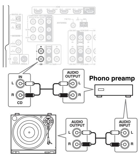
Turntable (MM) with no Phono Preamp Built-in
A phono preamp is necessary to connect a turntable that doesn't have a phono preamp built-in.
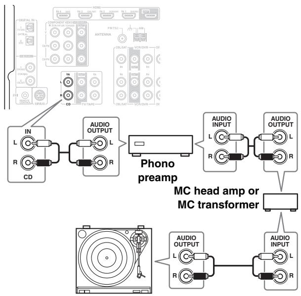
Turntable with an MC (Moving Coil) Cartridge
An MC head amp and phono preamp are necessary to connect a turntable with an MC (Moving Coil) cartridge.
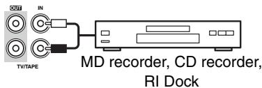
Connecting a Cassette, CDR, MiniDisc, or DAT Recorder
Step 1:
Choose a connection that matches your recorder (a, b, or c), and then make the connection.
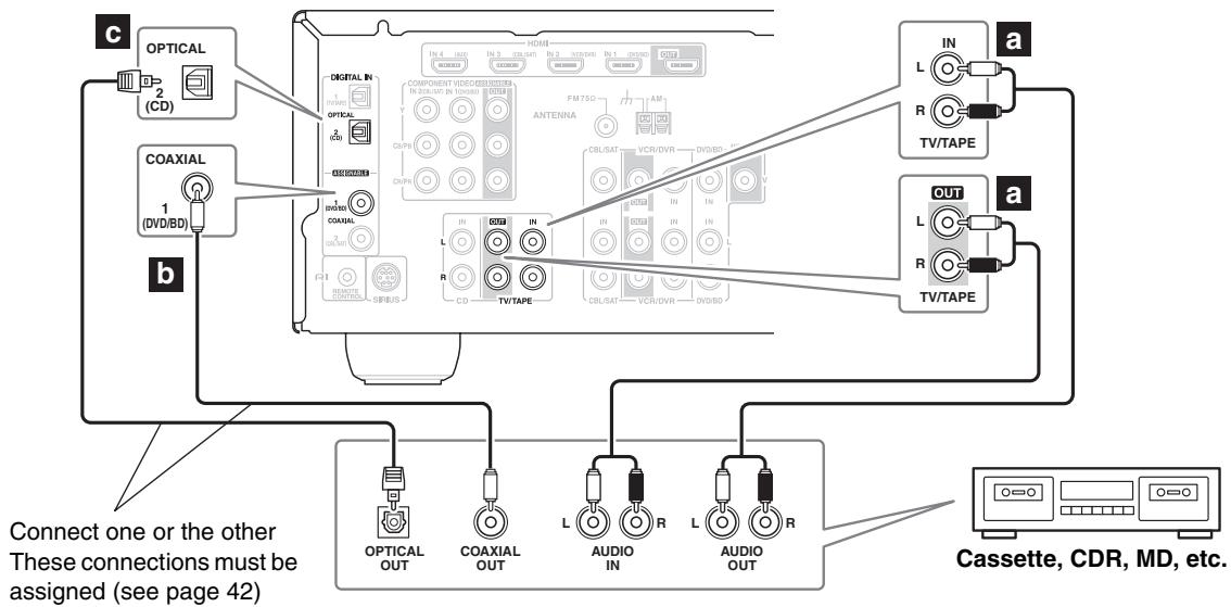
- With connection a, you can play and record.
- To connect the recorder digitally for playback, use connections a and b, or a and c.
| Connection | AV receiver | Signal flow | Cassette, CDR, MD, or DAT recorder |
| a | TV/TAPE IN L/R | ← | Analog audio L/R output |
| TV/TAPE OUT L/R | → | Analog audio L/R input | |
| b | DIGITAL IN COAXIAL 1 (DVD/BD) | ← | Digital coaxial output |
| c | DIGITAL IN OPTICAL 2 (CD) | ← | Digital optical output |
Connecting an RI Dock
Not all iPod models output video. For information about which iPod models are supported by the RI Dock, see the RI Dock's instruction manual.
If Your iPod Supports Video:
Connect your RI Dock's audio output jacks to the AV receiver's CBL/SAT IN or VCR/DVR IN L/R jacks, and connect its video output jack to the AV receiver's CBL/SAT IN or VCR/DVR IN V jack.
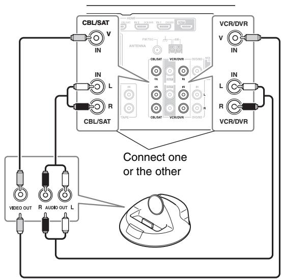
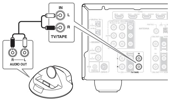
If Your iPod Doesn't Support Video:
Connect your RI Dock's audio output jacks to the AV receiver's TV/TAPE IN L/R jacks.
Notes:
- Enter the appropriate remote control code before using the AV receiver's remote controller for the first time (see page 78).
- Connect the RI Dock to the AV receiver with an RI cable (see page 37).
- Set the RI Dock's RI MODE switch to "HDD" or "HDD/DOCK".
- Set the AV receiver's Input Display to "DOCK" (see page 43).
- See the RI Dock's instruction manual for more information.
Connecting the Supplied UP-A1L Dock
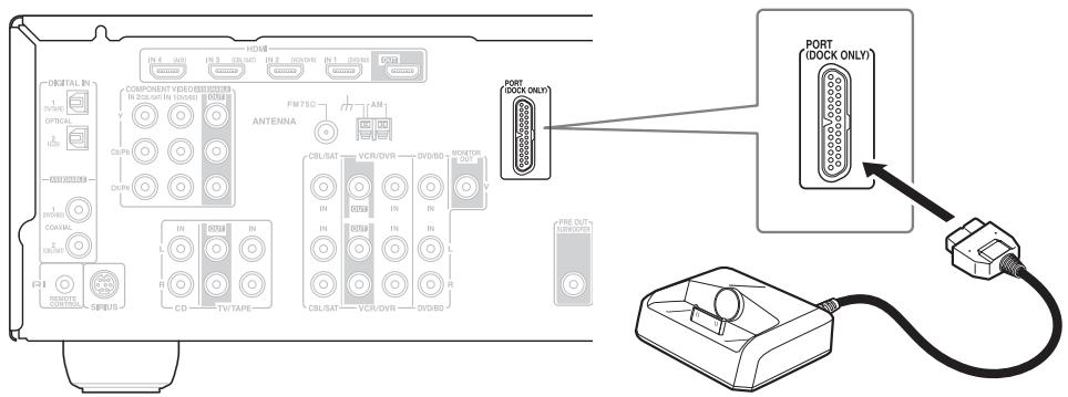
Notes:
- Do not connect components other than supplied UP-A1L dock with the PORT jack.
- While your iPod is seated in the Dock, its battery will be charged when the AV receiver is set to On or Standby.
- When UP-A1L is connected, the power consumption on standby mode slightly increases.
Connecting Onkyo RI Components
Step 1: Make sure that each Onkyo component is connected to the AV receiver with an analog audio cable (RCA).
Step 2: Make the necessary RI connections (see illustration below).
Step 3: If you're using an MD, CDR, or RI DOCK component, change the Input Display (see page 43).
With RI (Remote Interactive), you can use the following special functions:
Auto Power On/Standby
When you start playback on a component connected via RI, if the AV receiver is on Standby, it will automatically turn on and select that component as the input source. Similarly, when the AV receiver is set to Standby, all components connected via RI will also go on Standby.
Direct Change
When playback is started on a component connected via RI , the AV receiver automatically selects that component as the input source.
Remote Control
You can use the AV receiver's remote controller to control your other RI-capable Onkyo components. You must enter the appropriate remote control code first (see page 79). And remember to point the remote controller at the AV receiver and not the other component.
Notes:
- Use only RI cables for RI connections. RI cables are supplied with Onkyo players (DVD, CD, etc.).
- Some components have two RI jacks. You can connect either one to the AV receiver. The other jack is for connecting additional RI-capable components.
- Connect only Onkyo components to RI jacks. Connecting other manufacturer's components may cause a malfunction.
- Some components may not support all RI functions. Refer to the manuals supplied with your other Onkyo components.

Connecting the Power Cord
Notes:
- Before connecting the power cord, connect all your speakers and AV components.
- Plug the end of the power cord into a suitable wall outlet.
- Turning on the AV receiver may cause a momentary power surge that might interfere with other electrical equipment on the same circuit. If this is a problem, plug the AV receiver into a different branch circuit.
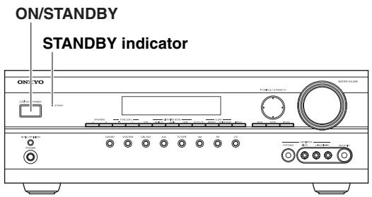
Turning On and Standby
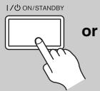
AV receiver
Remote controller
On the AV receiver, press the [ON/STANDBY] button.
On the remote controller, press the [RECEIVER] button, followed by the [ON/STANDBY] button.
The AV receiver comes on, the display lights up, and the STANDBY indicator goes off.
To turn the AV receiver off, press the [ON/STANDBY] button, or press the remote controller's [ON/STANDBY] button. The AV receiver will enter Standby mode. To prevent any loud surprises the next time you turn on the AV receiver, turn down the volume before you turn it off.
Up and Running in a Few Easy Steps
To get your system up and running with the minimum of fuss, here's a few pointers to help you configure the AV receiver before you use it for the very first time. These settings only need to be made once.
■ Do the 2EQ Room Correction and Speaker Setup—this is essential!

See "Audyssey 2EQTM Room Correction and Speaker Setup" on page 39.
Did you connect a component to component video input or digital audio input?
If you did, see "Component Video Input Setup" on page 42, or "Digital Input Setup" on page 42 respectively.
Did you connect an Onkyo MD recorder or CD recorder?
If you did, see "Changing the Input Display" on page 43.
This section explains the settings that you need to make before using the AV receiver for the very first time.
Audyssey 2EQ™ Room Correction and Speaker Setup
With the supplied calibrated microphone,
Audyssey 2EQ automatically determines the number of speakers connected, their size for purposes of bass management, optimum crossover frequencies to the subwoofer (if present), and distances from the primary listening position. Audyssey 2EQ then removes the distortion caused by room acoustics by capturing room acoustical problems over the listening area in both the frequency and time domain. The result is clear, well-balanced sound for everyone. Enabling Audyssey 2EQ allows you to also use Audyssey Dynamic EQ™, which maintains the proper octave-to-octave balance at any volume level. (See pages 74)
Before using this function, connect and position all of your speakers.
If Audyssey Dynamic EQ is set to "On", Audyssey Dynamic VolumeTM becomes available.
About Audyssey Dynamic EQ
Audyssey Dynamic EQ solves the problem of deteriorating sound quality as volume is decreased by taking into account human perception and room acoustics. Dynamic EQ selects the correct frequency response and surround levels moment-by-moment at any user-selected volume setting. The result is bass response, tonal balance, and surround impression that remain constant despite changes in volume. Dynamic EQ combines information from incoming source levels with actual output sound levels in the room, a prerequisite for delivering a loudness correction solution. Audyssey Dynamic EQ works in tandem with Audyssey 2EQ to provide well-balanced sound for every listener at any volume level.
About Audyssey Dynamic Volume
Audyssey Dynamic Volume solves the problem of large variations in volume level between television programs, commercials, and between the soft and loud passages of movies. Dynamic Volume looks at the preferred volume setting by the user and then monitors how the volume of program material is being perceived by listeners in real time to decide whether an adjustment is needed. Whenever necessary, Dynamic Volume makes the necessary rapid or gradual adjustments to maintain the desired playback volume level while optimizing the dynamic range. Audyssey Dynamic EQ is integrated into Dynamic Volume so that as the playback volume is adjusted automatically, the perceived bass response, tonal balance, surround impression, and dialog clarity remain the same whether watching movies, flipping between television channels, or changing from stereo to surround sound content.
Measurement Positions
To create a listening environment in which several people can enjoy your home theater simultaneously, Audyssey 2EQ takes measurements at three positions within the listening area.
① First measurement point
Also referred to as the Main Listening Position this refers to the most central position where one would normally sit within the listening environment. 2EQ uses the measurements from this position to calculate speaker distance, level, polarity, and the optimum crossover value for the subwoofer.
② Second measurement point
The right side of the listening area.
③ Third measurement point
The left side of the listening area.
The distances between points 1 and 2 and points 1 and 3 must be at least 1 meter.
From the examples below, choose the listening area that best matches yours and place the microphone accordingly when prompted.
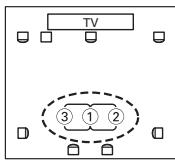
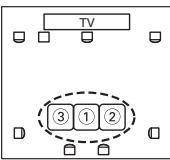
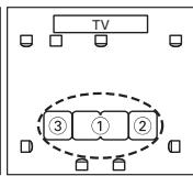
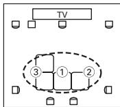
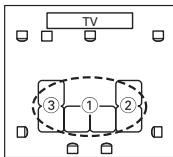
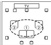
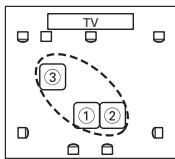
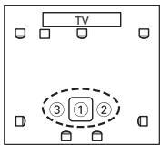
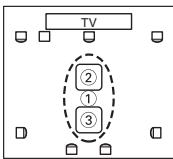
: Listening area
□: Listening position
Using Audyssey 2EQTM
Notes:
- If the AV receiver is muted, it will be unmuted automatically when the Audyssey 2EQ Room Correction and Speaker Setup starts.
- Room correction and speaker setup cannot be performed while a pair of headphones is connected.
- It takes about 10 minutes to complete the room correction and speaker setup for three positions. Total measurement time varies depending on the number of speakers.
- Do not connect or disconnect any speakers during room correction and speaker setup.
1 Turn on the AV receiver.
Notes:
- Before starting Audyssey 2EQ Room Correction and Speaker Setup, arrange the room and connect the speakers as you would for enjoying movies. Changes to the room after auto setup requires you run the auto setup again, as room EQ characteristics may have changed.
- When starting the room correction and speaker setup, do not stand between the speakers and microphone, and avoid obstacles blocking the path between speakers and microphone. This will produce inaccurate results.
- Position the microphone at ear height of a seated listener with the microphone tip pointed directly at the ceiling using a tripod. Do not hold the microphone in your hand during measurements as this will produce inaccurate results.
- Make the room as quiet as possible. Background noise can disrupt the room measurements. Close windows, silence cell phones, televisions, radios, air conditioners, fluorescent lights, home appliances, light dimmers, or other devices.
- Cell phones should be turned off or placed away from all audio electronics during the measurement process as Radio Frequency Interference (RFI) may cause measurement disruptions (even if the cell phone is not in use).
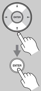
3 Press [ENTER].
The room calibration and speaker setup starts.
![ONKYO UP-A1L - Press [ENTER]. - 1](/content/2025/01/151778/images/e61231670b7ae5d70224b3f6796b28638eec727ab9238bf084aac30032f6d575.jpg)
Auyes
Test tones are played through each speaker as Audyssey 2EQ Room Correction and Speaker Setup runs. This process takes a few minutes. Please refrain from talking during measurements and do not stand between speakers and the microphone.
Note:
You can cancel the Room Correction and Speaker Setup at any point in this procedure simply by disconnecting the setup microphone.
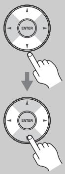
4 When the following display appears, move the speaker setup microphone to measurement point ② (page 39), and then press [ENTER].
Set M i c at 2nd.
![ONKYO UP-A1L - When the following display appears, move the speaker setup microphone to measurement point ② (page 39), and then press [ENTER]. - 1](/content/2025/01/151778/images/10468537b8d77739244968b8a8a0768cc20b6e64b5dbd045bf9cecc38554038e.jpg)
Audyssey 2EQ performs more measurements. This takes a few minutes.
5
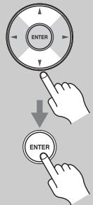
When the following display appears, move the speaker setup microphone to measurement point ③ (page 39), and then press [ENTER].
Set Nic 3rd

Audyssey 2EQ^TM performs more measurements.
This takes a few minutes.
When the measurements are complete, the results are calculated and saved automatically.
Caiuui t i
6
When the room correction and speaker setup is complete, disconnect the speaker setup microphone.
Unplug Setuplic
Note:
When the room correction and speaker setup is complete, "6. Equalizer" (page 72) will be set to "Audyssey."
Error Messages
While the room correction and speaker setup is in progress, one of the following error messages may appear:
Ambient noise is too high
Noise EPRF!
This message appears if there's too much background noise and the measurements cannot be performed properly. Remove the source of the noise and try again.
Speaker Detect Errors
P Detect EPR
This message appears if one of the speaker-related errors below occurs.
One of the front speakers has not been detected.
- One of the surround speakers has not been detected.
Write Error
H
This message appears if saving fails.
Mismatch Error
Smpatching Err!
This message appears if a speaker that was detected during the 1st measurement is not detected during the 2nd or 3rd measurements. If this message appears, check your speaker connections, and then try again.
To Retry the Room Correction and Speaker Setup
Press the [ENTER] button.
Make sure speakers that cannot be detected are connected properly.

Changing the Speaker Settings Manually
If you wish to make changes to the settings found during the room correction and speaker setup, follow the directions on pages 70-72.
Using a Powered Subwoofer
If you're using a powered subwoofer, as it outputs very low-frequency sound and its position is usually low down, it may not be detected by the Audyssey 2EQ Room Correction and Speaker Setup. In this case, increase the subwoofer's volume, select its highest crossover frequency, and then try running the Audyssey 2EQ Room Correction and Speaker Setup again. Note that if the volume is set too high and the sound distorts, it may not be detected, so use an appropriate volume level.
Component Video Input Setup
If you connect to a COMPONENT Video IN, you must assign it to an input selector. For example, if you connect your DVD/BD player to COMPONENT Video IN 2, you should assign it to the DVD/BD input selector.
| Input selector | Default assignment |
| DVD/BD | IN1 |
| VCR/DVR | ----- |
| CBL/SAT | IN2 |
| AUX | ----- |
| TV/TAPE | ----- |
| CD | ----- |
| PORT | ----- |
1
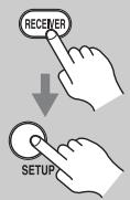
Press the [RECEIVER] button, followed by the [SETUP] button.
2
Use the Up and Down [▲]/[▼] buttons to select "1-component", and then press [ENTER].
3
Use the Up and Down [▲]/[▼] buttons to select an input selector, and use the Left and Right [▲]/[▶] buttons to select:
IN1: Select if the video component is connected to COMPONENTVIDEO IN 1.
IN2: Select if the video component is connected to COMPONENTVIDEO IN 2.
-
-
-
- : Select if you're not using the COMPONENTVIDEO OUT.
-
-

4
Press the [SETUP] button.
Setup closes.
Note:
This procedure can also be performed on the AV receiver by using its [SETUP] button, arrow buttons, and [ENTER] button.
Digital Input Setup
To enjoy Dolby Digital and DTS, you must connect your DVD/BD player to the AV receiver by using a digital audio connection (coaxial or optical). Here are the default assignments.
| Input selector | Default assignment |
| DVD/BD | COAX1 |
| VCR/DVR | -------- |
| CBL/SAT | COAX2 |
| AUX | -------- |
| TV/TAPE | OPT1 |
| CD | OPT2 |
| PORT | -------- |
With this function, you can assign digital inputs to input sources. For example, if you connect your DVD/BD player to DIGITAL IN OPTICAL 1, you'll need to assign that input (OPT1) to the DVD input source.
You can change the assignments as follows.
1
Press the [RECEIVER] button, followed by the [SETUP] button.

2
Use the Up and Down [] / [] buttons to select "2.Digital Audio", and then press [ENTER].
3
Use the Up and Down [ ] / [ ] buttons to select an input selector, and then use the Left and Right [ ] / [ ] buttons to select:
COAX1: Select if the component is connected to DIGITAL IN COAXIAL 1.
COAX2: Select if the component is connected to DIGITAL IN COAXIAL 2.
OPT1: Select if the component is connected to DIGITAL IN OPTICAL 1.
OPT2: Select if the component is connected to DIGITAL IN OPTICAL 2.
- - - - : Select if the component is connected to an analog input.

4
Press the [SETUP] button. Setup closes.
Notes:
- Make sure you also set your digital sources to send out a digital signals. Please refer to the digital sources' manual.
- This procedure can also be performed on the AV receiver by using its [SETUP] button, arrow buttons, and [ENTER] button.
Changing the Input Display
If you connect an RI-capable Onkyo MiniDisc recorder, CD recorder, or RI Dock to the TV/TAPE IN/OUT jacks, or connect an RI Dock to the CBL/SAT IN or VCR/DVR IN jacks, for RI to work properly, you must change this setting.
This setting can only be changed on the AV receiver.
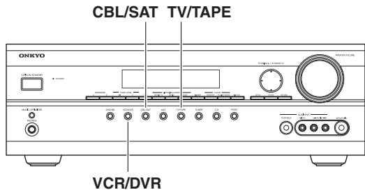
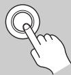
1
TV/TAPE
or

CBL/SAT
or

VCR/DVR
Press the [TV/TAPE], [CBL/SAT] or [VCR/DVR] input selector button so that "TV/TAPE", "CBL/SAT" or "VCR/DVR" appears on the display.
TUTape
CBL/SHT
UCR×DUR

2
TV/TAPE
or

CBL/SAT
or

VCR/DVR
Press and hold down the [TV/TAPE], [CBL/SAT] or [VCR/DVR] input selector button (about 3 seconds) to change the setting.
Repeat this step to select MD, CDR, or DOCK.
For the TV/TAPE input selector, the setting changes in this order:
TV/TAPE MD CDR
DOCK
←
For the CBL/SAT input selector, the setting changes in this order: CBL/SAT DOCK
For the VCR/DVR input selector, the setting changes in this order:
VCR/DVR DOCK
Note:
DOCK can be selected for the TV/TAPE or CBL/SAT or VCR/DVR input selector, but not at the same time.
Basic AV receiver Operation
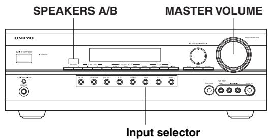
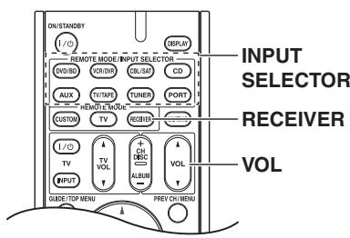
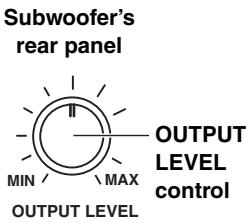
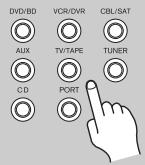
1
AV receiver

Remote controller
Use the AV receiver's input selector buttons to select an input source.
To select an input source with the remote controller. Press the [RECEIVER] button, and then press its INPUT SELECTOR buttons.
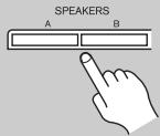
2
AV receiver
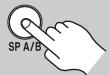
Remote controller
To turn the speakers on or off, use the AV receiver's SPEAKERS [A] and [B] buttons, or use the remote controller's [SP A/B] button.
Pressing the remote controller's [SP A/B] button cycles through the following settings:
Speaker Set A Speaker Set A&B Speaker Set B Off
Note that while speaker set B is on, speaker set A is reduced to 2.1-channel playback.
See page 18 for more information about speaker sets A and B.
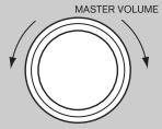
3
AV receiver
Remote controller
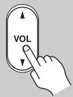
5
Start playback on the source component.
To watch a BD, DVD, or other video source, on your TV, select the video input that's connected to the AV receiver's HDMI OUT, COMPONENT VIDEO OUT, or MONITOR OUT.
On some DVD/BD players, you may need to change the digital or HDMI audio output settings.
To adjust the volume, use the MASTER VOLUME control or the remote controller's VOL [] / [] button.
Since the AV receiver is designed for home theaters, it has a wide volume range for precise adjustment. The volume can be set to Min, 1 through 79, or Max.
Note:
When the subwoofer volume level is set to a positive (+) value, the maximum master volume level is reduced proportionally.
To set the level of the subwoofer, use the OUTPUT LEVEL control.
Because our ears are less sensitive to very low bass sounds, there's a temptation to set the level of the subwoofer too high. As a rule of thumb, set the subwoofer level to what you think is the optimal level, and then back it off slightly.
Select a listening mode and enjoy!
See "Using the Listening Modes" on page 64.
This section explains functions that can be used with any input source.
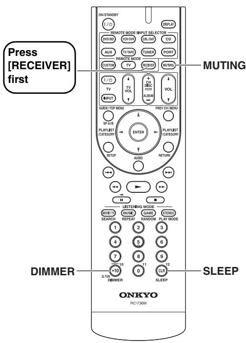
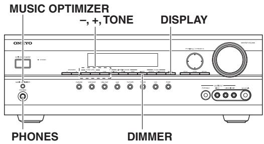
Setting the Display Brightness
You can adjust the brightness of the display.
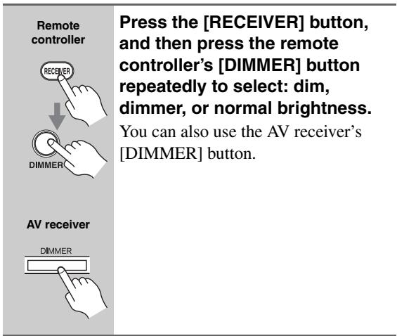
Muting the AV receiver
You can temporarily mute the output of the AV receiver.
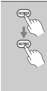
Press the [RECEIVER] button, and then press the remote controller's [MUTING] button.
The output is muted and the MUTING indicator flashes on the display.

To unmute the AV receiver, press the remote controller's [MUTING] button again, or adjust the volume. The output is unmuted and the MUTING indicator goes off.
Muting is cancelled when the AV receiver is set to Standby.
Using the Sleep Timer
With the sleep timer, you can set the AV receiver so that it turns off automatically after a specified period.
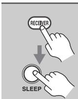
Press the [RECEIVER] button, and then press the remote controller's [SLEEP] button repeatedly to select the required sleep time.
You can set the sleep time from 90 to 10 minutes in 10 minute steps.
The SLEEP indicator appears on the display when the sleep timer has been set, as shown. The specified sleep time appears on the display for about 5 seconds, then the previous display reappears.
SLEEP indicator
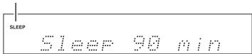
To cancel the sleep timer, press the [SLEEP] button repeatedly until the SLEEP indicator disappears.
To check the remaining sleep time, press the [SLEEP] button. Note that if you press the [SLEEP] button while the sleep time is being displayed, you'll shorten the sleep time by 10 minutes.
Using Headphones
For private listening, you can connect a pair of stereo headphones (1/4-inch phone plug) to the AV receiver's PHONES jack.
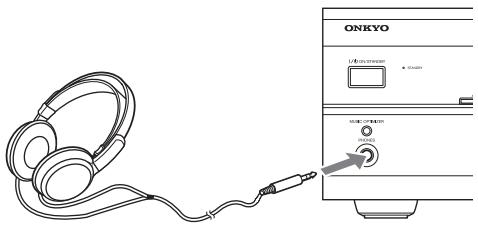
Notes:
Always turn down the volume before connecting your headphones.
- While the headphones plug is inserted in the PHONES jack, the speakers are turned off.
- Speaker sets A and B are turned off while the headphones plug is inserted in the PHONES jack.
- When you connect a pair of headphones, the listening mode is set to Stereo, unless it's already set to Mono, Stereo, or Direct, in which case it stays the same.
Adjusting the Bass & Treble
You can adjust the bass or treble for speaker set A's front speakers, except when the Direct listening mode is selected.
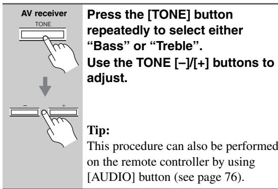
Bass
You can boost or cut low-frequency sounds output by the front speakers from -10dB to +10dB in 2 dB steps.
Treible
You can boost or cut high-frequency sounds output by the front speakers from -10dB to +10dB in 2 dB steps.
Displaying Source Information
You can display various information about the current input source as follows.
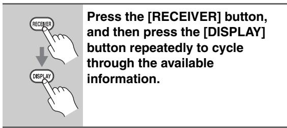
Note:
This procedure can also be performed on the AV receiver by using its [DISPLAY] button.
The following information can typically be displayed:
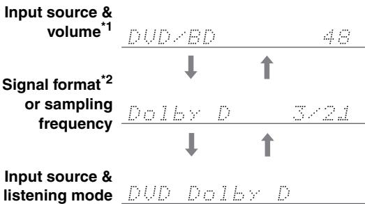
1 When AM or FM radio is used, the band, preset number, and frequency are displayed.
2 If the input signal is analog, or AM or FM radio is selected, no format information is displayed. If the input signal is PCM, the sampling frequency is displayed. If the input signal is digital but not PCM, the signal format is displayed. Information is displayed for about 3 seconds, then the previous display reappears.
Interpreting Surround Channel Information

A: The number of front channels (front left, front right, and center).
B: The number of surround channels (surround left and surround right).
C: LFE channel for subwoofer (1 means yes).
Using the Music Optimizer
The Music Optimizer function enhances the sound quality of compressed music files. Use it with music files that use "lossy" compression, such as MP3.
MUSIC OPTIMIZER

To turn the Music Optimizer "On" or "Off", use the AV receiver's [MUSIC OPTIMIZER] button.
The setting is stored individually for each input selector.
Off: Music Optimizer off (default).
On: Music Optimizer on.
Tip:
This procedure can also be performed on the remote controller by using [AUDIO] button (see page 77).
Note:
The Music Optimizer function only works with PCM digital audio input signals with a sampling rate below 48kHz and analog audio input signals. The Music Optimizer is disabled when the Direct listening mode is selected.
Specifying the Digital Signal Format
The following table shows the display indicator for each digital signal format.
| Format | Display |
| Dolby Digital | ☐ D |
| DTS | ☐ ☐ |
| PCM | PCM |
Normally, the AV receiver detects the format of digital input signals automatically. However, if you experience either of the following issues when playing PCM or DTS sources, you can specify the signal format manually.
- If the beginnings of tracks from a PCM source are cut off, try the PCM setting.
- If noise is produced when fast forwarding or rewinding a DTS CD, try the DTS setting.
- The setting is stored individually for each input selector.
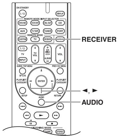
1
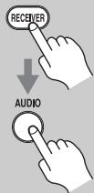
Press the [RECEIVER] button, and then press and hold [AUDIO] button for about 8 seconds.
2
While "Auto" is displayed (about 3 seconds), use the Left and Right [<]/<> buttons to select: PCM, DTS, or Auto.
PCM:
Only 2-channel PCM format input signals will be heard. If the input signal is not PCM, the PCM indicator will flash and there will be no sound.
DTS:
Only DTS format input signals will be heard. If the input signal is not DTS, the DTS indicator will flash and there will be no sound.
Auto (default):
The format is detected automatically. If no digital input signal is present, the corresponding analog input is used instead.
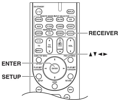
AM/FM Frequency Step Setup
For AM/FM tuning to work properly, you must specify the AM/FM frequency step used in your area. Note that when this setting is changed, all radio presets are deleted.
1
Press the [RECEIVER] button, followed by the [SETUP] button.
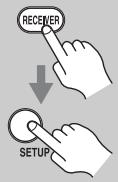
2
Use the Up and Down [] / [] buttons to select "8.Hardware", and then press [ENTER].
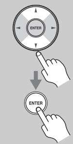

3
Use the Up and Down [▲]/[▼] buttons to select "FM/AM".
FIM产M 50k 9k
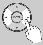
4
Use the Left and Right [] / [] buttons to select:
200k/10k:
Select if 200k / 10k steps are used in your area.
50k/9k: Select if 50k/9k steps are used in your area.

5
Press the [SETUP] button.
Setup closes.
Note:
This procedure can also be performed on the AV receiver by using its [SETUP] button, arrow buttons, and [ENTER] button.
Listening to AM/FM Stations
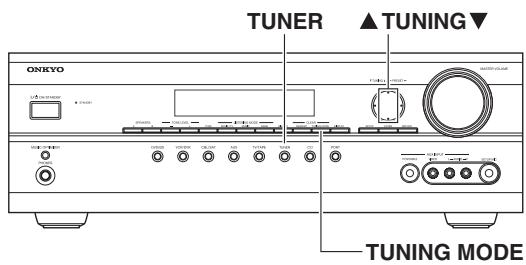
With the built-in tuner, you can enjoy AM and FM radio stations and store your favorite stations as presets for easy selection.

Use the [TUNER] input selector button to select "AM" or "FM".
In this example, FM has been selected.
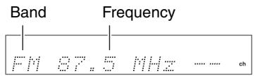
(Actual display depends on country.)
Tuning into AM/FM Radio Stations
Auto Tuning Mode

Press the [TUNING MODE] button so that the AUTO indicator appears on the display.
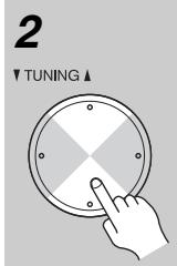
Press the TUNING Up or Down [▲]/[▼] button.
Searching stops when a station is found.
When tuned into a station, the TUNED indicator appears. When tuned into a stereo FM station, the FM STEREO indicator also appears.
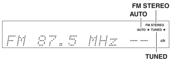
Manual Tuning Mode
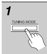
Press the [TUNING MODE] button so that the AUTO indicator disappears from the display.
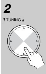
Press and hold the TUNING Up or Down [▲]/[▼] button.
The frequency stops changing when you release the button. Press the button repeatedly to change the frequency one step at a time.
This model changes FM/AM frequency in 200k / 10k (or 50k / 9k) Hz steps.
In Manual Tuning mode, FM stations will be in mono.
Tuning into Weak FM Stereo Stations
If the signal from a stereo FM station is weak, it may be impossible to get good reception. In this case, switch to Manual Tuning mode and listen to the station in mono.
Note:
You can also use the remote controller's Up and Down [ ] / [ ] buttons to tune the radio.
Tuning into Stations by Frequency
You can tune into AM and FM stations directly by entering the appropriate frequency.
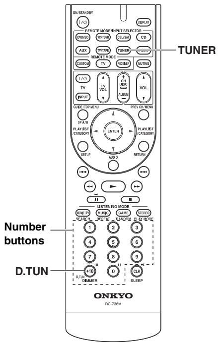
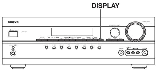
Displaying AM/FM Radio Information
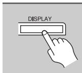
Press the [DISPLAY] button to display the available information.
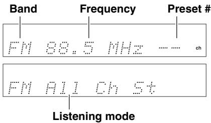
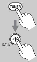
1
Press the [TUNER] button repeatedly to select "AM" or "FM", followed by the [D.TUN] button.
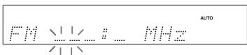
(Actual display depends on country.)
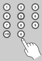
2
Within 8 seconds, use the number buttons to enter the frequency of the radio station.
For example, to tune to 87.5 (FM), press 8, 7, 5.
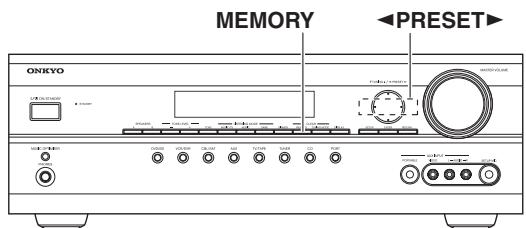
Presetting AM/FM Stations
You can store a combination of up to 40 of your favorite AM and FM radio stations.
| 1 | Tune into the AM or FM station you want to store as a preset. |
| 2 MEMORY | Press the [MEMORY] button. The preset number flashes. |
| 3 → PRESET | While the preset number is flashing (about 8 seconds), use the PRESET [←]/[►] buttons to select a preset from 1 through 40. |
| 4 MEMORY | Press the [MEMORY] button again to store the station. The station is stored and the preset number stops flashing. Repeat this procedure for all of your favorite stations. |
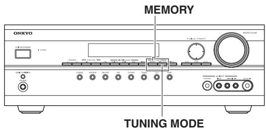
Deleting Presets
| 1 | Select the preset that you want to delete. See the next section. |
| 2 CLEAR MEMORY TUNING MODE | While holding down the [MEMORY] button, press the [TUNING MODE] button. The preset is deleted and its number disappears from the display. |
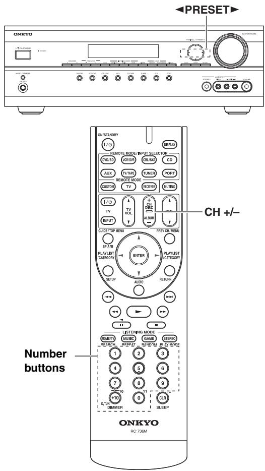
Selecting Presets
| AV receiver → PRESET or Remote controller +CH or 1 2 3 4 5 6 7 8 9 +10 0 | To select a preset, use the PRESET [▲]/[▶] buttons or the remote controller's CH [+/−] button. You can also use the remote controller's number buttons to select a preset directly. |
Listening to Satellite Radio
To listen to Satellite Radio, you'll need to connect a SIRIUS Satellite Radio tuner (sold separately) to your Sirius-Ready receiver. SIRIUS Satellite Radio is available to residents of the US (except Alaska and Hawaii) and Canada.
Satellite Radio delivers a variety of commercial-free music from categories ranging from Pop, Rock, Country, R&B, Dance, Jazz, Classical and many more plus coverage of all the top professional and college sports including play by play games from select leagues and teams. Additional programming includes expert sports talk, uncensored entertainment, comedy, family programming, local traffic and weather and news from your most trusted sources.
Once you've purchased a SIRIUS tuner you'll need to activate it and subscribe to begin enjoying the service. Easy to follow installation and setup instructions are provided with the SIRIUS tuner. There are a variety of programming packages available, including the option of adding "The Best of XM" programming to the SIRIUS service. The "Best of XM" service is not available to SIRIUS Canada subscribers at this time. Please check with SIRIUS Canada for any updates using the numbers and web address below.
Family friendly packages are also available to restrict channels featuring content that may be inappropriate for children.
To subscribe to SIRIUS, U.S. and Canadian customers can call 1-888-539-SIRI (1-888-539-7474) or visit sirius.com (US) or siriuscanada.ca (Canada).
SIRIUS, XM and all related marks and logos are trademarks of Sirius XM Radio Inc. and its subsidiaries.

All rights reserved. Service not available in Alaska and Hawaii.
Setting Up the SiriusConnect™ Home Tuner
The optional SiriusConnect Home tuner kit includes everything for easy home installation, including the SiriusConnect receiver, indoor/outdoor antenna with 21-foot cable, 8-pin mini DIN connector cable, and an AC power adapter. See the SiriusConnect Home tuner's instructions for more information.
Use the 8-pin mini DIN connector cable to connect the SiriusConnect receiver to the SIRIUS antenna jack on the rear of the AV receiver.
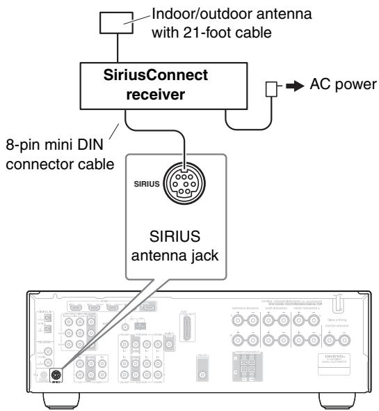
To use the included antenna indoors, you must place it at a north-, west-, or east-facing window, depending on where you live. If this isn't possible, you'll need to install it outside, away from any overhead obstructions.
Positioning the Antenna
For a consistent satellite signal, the antenna must be positioned correctly. Use the following map to determine which area you are in and position the antenna accordingly.
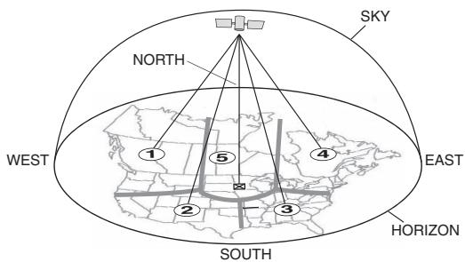
Area 1: Point the antenna toward the sky in the east, northeast, or southeast, either through a window or outside.
Area 2: Point the antenna toward the sky in the north or northeast, either through a window or outside.
Area 3: Point the antenna toward the sky in the north or northwest, either through a window or outside.
Area 4: Point the antenna toward the sky in the west, northwest, or southwest, either through a window or outside.
Area 5: Put the antenna outside and point it straight up. The antenna cannot be used indoors.
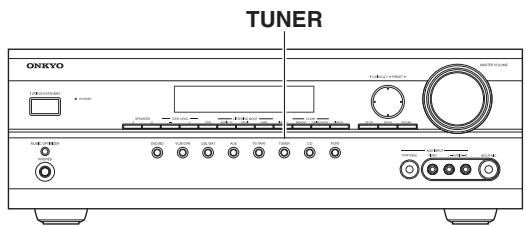
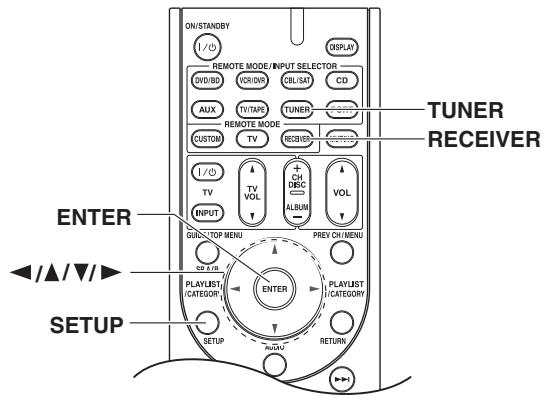
Setting the Satellite Radio Mode
1
Remote controller

Press the [RECEIVER] button, followed by the [SETUP] button.
2
Remote controller

Use the Up and Down [] / [] buttons to select "8. Hardware", and then press [ENTER].
3
Remote controller
Use the Up and Down [] / [] buttons to select "SATRadio".
Pressing the Left and Right [] / [] buttons cycles through the following options: None SIRIUS
None: Select if you're not using Satellite Radio.
SIRIUS: Select to use SIRIUS Satellite Radio.
4
Remote controller

Press the [SETUP] button.
Selecting SIRIUS Satellite Radio
1
AV receiver TUNER

Remote controller
On the AV receiver, press the [TUNER] INPUT SELECTOR button repeatedly to select SIRIUS.
On the remote controller, press the [RECEIVER] REMOTE MODE button, and then press the [TUNER] INPUT SELECTOR button repeatedly to select SIRIUS.
If "CHECK SR TUNER" appears on the display, make sure the SiriusConnect receiver is connected properly. If "ANTENNA ERROR" appears, make sure the antenna is connected properly.
Signing Up for SIRIUS Satellite Radio
Before you can use SIRIUS Satellite Radio, you must first sign up for an account. You'll need a major credit card and your SIRIUS Satellite Radio ID, which you can get from the AV receiver, as explained below, or from the SiriusConnect Home tuner package.
1
Remote controller
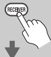

Press the [RECEIVER] button, followed by the [SETUP] button.
2
Remote controller
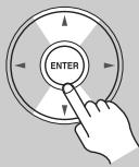
Use the Up and Down [A]/[▼] buttons to select
"9. Antenna Aim", and then press [ENTER].
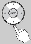
3
Remote controller
Use the Up and Down [] / [] buttons to select "Sirius ID".
Your SIRIUS Satellite Radio ID number is displayed. Write it below.
![ONKYO UP-A1L - Use the Up and Down [] / [] buttons to select "Sirius ID". - 1](/content/2025/01/151778/images/b30ee12b10612dd3d4d3b460a9643255fd2f6deea4a2e1a960bb27a7d0064925.jpg)
4
To sign up, go to: http://activate.siriusradio.com Or call: 1-888-539-SIRIUS (7474)
Note:
After you've activated your subscription with SIRIUS Satellite Radio, your SIRIUS Satellite Radio ID number will no longer be displayed when you select channel 0.
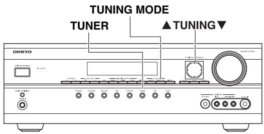
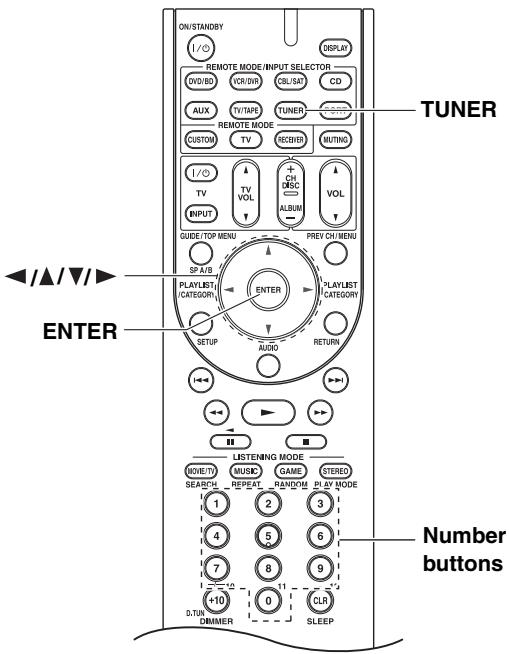
Selecting SIRIUS Satellite Radio Channels
There are three ways to select SIRIUS Satellite Radio channels:
- Channel Search mode: select any channel.
- Category Search mode: select channels by category.
- Direct tuning: enter channel number.
Channel Search Mode
1
AV receiver TUNER

TUNING MODE
Remote controller


Press the [TUNER] button, and then press the [ENTER] button repeatedly to select Channel Search mode.
Channel Search
This procedure can also be performed on the AV receiver by using its [TUNER] button, and [TUNING MODE] button.
2
AV receiver INING

Remote controller
Use the Up and Down [] / [] buttons to select a channel.
U50 Hot Jamz
Channel number Channel name
You can also use the remote controller's Left and Right Arrow [] / [] buttons to select a category.
Category Search Mode
1
AV receiver TUNER

TUNING MODE
Remote controller
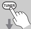

Press the [TUNER] button, and then press the [ENTER] button repeatedly to select Category Search mode.
Category Search
This procedure can also be performed on the AV receiver by using its [TUNER] button, and [TUNING MODE] button.
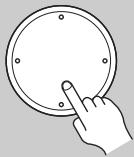
2
AV receiver
TUNING
Remote
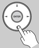
controller
Use the Left and Right [] / [] buttons to select a category, and use the Up and Down [] / [] buttons to select a channel in that category.

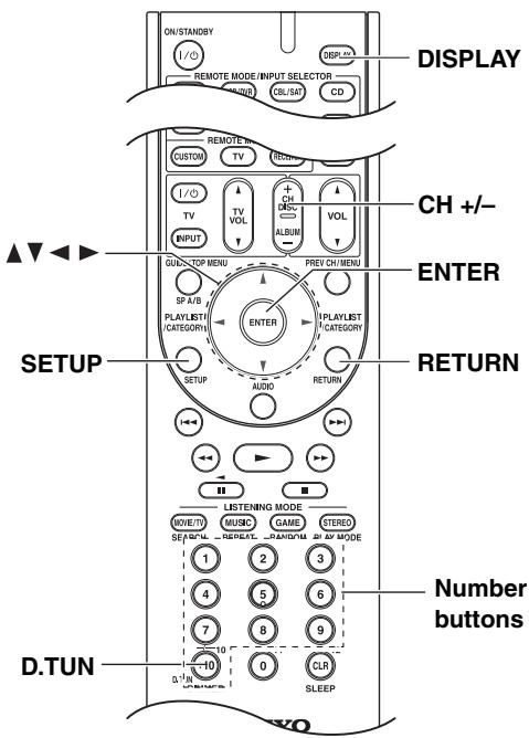
Direct Tuning
You can select a SIRIUS Satellite Radio channel directly by entering its number with the remote controller.
1
Remote controller
Press the [D.TUN] button.
2
Remote controller


Within 8 seconds, use the number buttons to enter the channel number.
For example, to select channel #20, press [0], [2], and [0], or press [2], [0], and [ENTER].
Notes:
- If you select an unavailable channel, "INVALID CHANNEL" appears on the display.
- If you select a channel that you are not subscribed to, "CALL SIRIUS" appears on the display.
- Channels that are locked must be unlocked before you can listen to them. See "Parental Lock" on page 58 for more information.
Selecting Channels on the AV receiver:

1 AV receiver
TUNING MODE
Press the [TUNING MODE] button repeatedly to select Channel Search mode or Category Search mode.
2 AV receiver
Press [ENTER] repeatedly to select a category.
3 AV receiver
TUNING
Use the TUNING Up and Down [▲]/[▼] buttons to select a channel.
In Channel Search mode, you can select any channel.
In Category Search mode, you can only select channels from the currently selected category.
Selecting the Previous Channel:
AV receiver
Remote controller

To listen to the previously selected SIRIUS Satellite Radio channel, press the [RETURN] button.
Presetting SIRIUS Channels
You can store a combination of up to 40 of your favorite SIRIUS Satellite Radio channels and AM/FM radio stations as presets.
| 1 | Tune into the SIRIUS channel that you want to store as a preset. |
| 2AV receiver MEMORY | Press the [MEMORY] button. The preset number flashes. |
| 3AV receiver → PRESET | While the preset number is flashing (about 8 seconds), use the PRESET [←] /[▶] buttons to select a preset from 1 through 40. |
| 4AV receiver MEMORY | Press the [MEMORY] button again to store the channel. The channel is stored and the preset number stops flashing. Repeat this procedure for all of your favorite SIRIUS Satellite Radio channels. |
Selecting Presets
| AV receiver → PRESET Remote controller +CH DISC ALBUM ●●●●●●●●●●●●●●●●●●●●●●●●●●●●●●●●●●●●●●●●●●●●●●●●●●●●●●●●●●●●●●●●●●●●●●●●●●●●●●●●●●●●●●●●●●●●●●●●●●●● ●●●●●●●●●●●●●●●●●●●●●●●●●●●●●●●●●●●●●●●●●●●●●●●●●●●●●●●●●●●●●●●●●●●●●●●●●●●●●●●●●●●●●●●●●●●●●●●●●●●● | ||
| 1 | 2 | 3 |
| 4 | 5 | 6 |
| 7 | 8 | 9 |
| +10 | 0 |
Deleting Presets
| 1 | Select the preset that you want to delete. See the previous section. |
| 2AV receiver CLEAR MEMORY TUNING MODE | While holding down the [MEMORY] button, press the [TUNING MODE] button. The preset is deleted and its number disappears from the display. |
Displaying SIRIUS Satellite Radio Information
Press the [DISPLAY] button repeatedly to cycle through the available information.
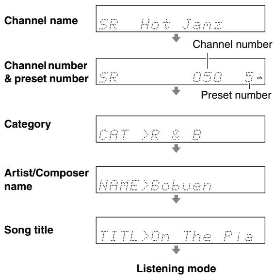
Note:
If the category, artist, or song title is not available, "---" will be displayed instead.
SIRIUS Satellite Radio Messages
The following messages may appear while using SIRIUS Satellite Radio.
ACQUIRING
The SiriusConnect receiver is acquiring the signal or no signal is present. Make sure the SiriusConnect Home tuner is connected properly and that there are no obstacles close by.
ANTENNA ERROR
Make sure the SiriusConnect Home tuner is connected properly.
SUB UPDATED
Displayed while your subscription is being updated. No operations can be performed until this message has cleared.
UPDATING XXX%
Displayed while the channel map is being updated. Wait until the updating is complete.
SIRIUS UPDATING
Displayed while the SiriusConnect receiver's firmware is being updated.
INVALID CHANNEL
Displayed if you select an unavailable channel.
CALL SIRIUS
Displayed when you select a channel to which you are not subscribed. Call SIRIUS if you want to subscribe.
CHECK SR TUNER
Displayed if the SiriusConnect receiver is not connected.
Make sure the SiriusConnect receiver is connected properly, and make sure its AC adapter is plugged in.
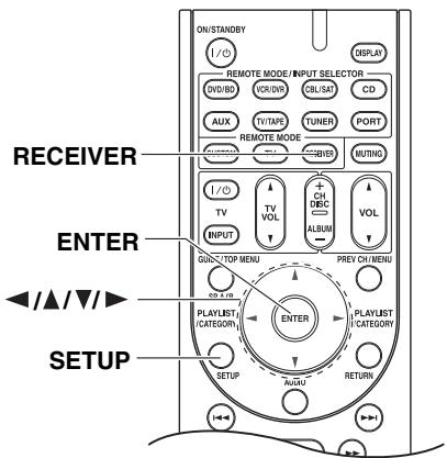
Positioning the SiriusConnect Home Tuner
You can check the signal strength of the SIRIUS Satellite Radio signal and adjust the position of the SiriusConnect Home antenna accordingly.
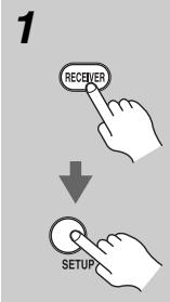
Press the [RECEIVER] button, followed by the [SETUP] button.
2
3
Use the Up and Down [▲]/[▼] buttons to select "9. Antenna Aim," and then press [ENTER].
。网打中电打门 门
Note:
If the "SATRadio" is set to "None" (see page 53), the "Antenna Aim" item is not available.
Adjust the position of the indoor/outdoor antenna connected to the SiriusConnect receiver so that the satellite (SAT) signal strength bar is as long as possible.
SAT#I
If you cannot receive a satellite signal, press the Down [▼] button to display the terrestrial (TER) signal strength meter and adjust your antenna so that the bar is as long as possible.
Terrestrial signals are only available in certain areas.
TERR
So long as the signal strength is good, you can enjoy SIRIUS Satellite Radio by using either satellite or terrestrial reception.
Parental Lock
You can lock out channels that you do not want to receive.
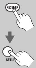
1
Press the [RECEIVER] button, followed by the [SETUP] button.
2
Use the Up and Down [] / [] buttons to select "10. Parental Lock", and then press [ENTER]. "Enter: < 0> " appears on the display.
Ee
Note:
If the "SATRadio" is set to "None" (see page 53), the "ParentalLock" item is not available.
3
Use the Left and Right [] / [] buttons to change the number displayed between the angle brackets < > ,and then press [ENTER].Repeat this for each digit in the PIN number.*
4
Use the Up and Down [ ] / [ ] buttons to select the channel that you want to lock out, for example:
858 Hot J amz
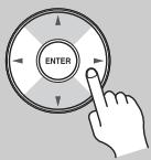
5
Press the Left and Right [] / [] buttons so that an asterisk appears next to the name, as shown below, and then press [ENTER].
850 HotJamz
The message "Locked" will appear on the display.

6
Press the [SETUP] button.
Setup closes.
To unlock a previously locked channel, select the locked channel (see step 1-4), press the Left and Right [] / [] buttons so that the asterisk disappears (see step 5), and then press [ENTER]. The message "Unlocked" will appear on the display.
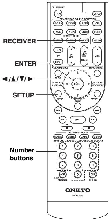
Changing the PIN Number
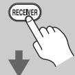
1

Press the [RECEIVER] button, followed by the [SETUP] button.
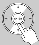
2
Use the Up and Down [A]/[▼] buttons to select "10. Parental Lock", and then press [ENTER].
Note:
If the "SATRadio" is set to "None" (see page 53), the "ParentalLock" item is not available.
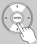
3
Use the Up and Down [ ] / [ ] buttons to select "Edit Code," and then press [ENTER].
"Enter: <0> " appears on the display.
Enter 1

4


Use the number buttons to enter the old PIN number.
If you enter the wrong PIN number, "Wrong Code!" appears on the display. You'll be returned to step 2, and will need to start again. "New : <0>" appears on the display.
New
:
<

5


Use the number buttons to enter the new PIN number.
"Confirm: < 0> " appears on the display.
Con
<

6

Enter the new PIN number again. If you enter the wrong PIN number, "Wrong Code!" appears on the display. You'll be returned to step 2, and will need to start again.
Press the [SETUP] button. Setup closes.

About the UP-A1L Dock
With the supplied UP-A1L Dock, you can easily play the music, photo, or movie stored on your Apple iPod through the AV receiver and enjoy great sound. You can use the AV receiver's remote controller to operate your iPod.
For the latest information on the Dock, see the Onkyo Web site at: www.onkyo.com
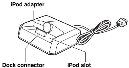
Compatible iPod models
Made for:
- 2nd Generation iPod touch
1st Generation iPod touch - iPod photo
- 5th Generation iPod (iPod with video)
- 4th Generation iPod
- 4th Generation iPod nano
- 3rd Generation iPod nano
- 2nd Generation iPod nano
1st Generation iPod nano - iPod mini
Note:
Before using the Dock, update your iPod with the latest software, available from the Apple Web site at: www.apple.com
Putting Your iPod in the Dock
- Turn on the AV receiver, and select the [PORT] selector.
- Align your iPod with the Dock's iPod slot, and carefully place your iPod in the slot, as shown.

Adjusting the iPod Adapter
The iPod adapter needs to be adjusted to match your particular iPod. If there's a gap between the back of your iPod and the adapter, turn the adapter counterclockwise to close the gap. Turning the adapter counterclockwise moves it forward. Turning it clockwise moves it backward.
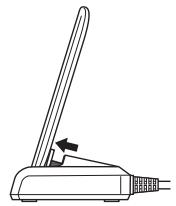
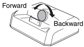
Notes:
- Make sure that the output level of the AV receiver is set to minimum.
- To prevent iPod connector damage, don't twist your iPod when inserting or removing it, and be careful not to knock over the Dock while your iPod is inserted.
- Do not take off your iPod from the Dock when you play back the music, photo, or movie stored on your iPod.
- Don't use the Dock with any other iPod accessories, such as FM transmitters and microphones, as they may cause a malfunction.
- It is recommended that you update your iPod software before using it with this unit. The updater for the iPod software is available at the Apple website.
Function Overview
Basic Operation
Note:
The AV receiver may take several seconds to startup, so you might not hear the first few seconds of the first song.
- Auto Power On Function
If you start iPod playback while the AV receiver is on Standby, the AV receiver will automatically turn on and select your iPod as the input source. Then, your iPod will start playback.
- Direct Change Function
If you start iPod playback while listening to another input source, the AV receiver will automatically select your iPod as the input source.
- Using the AV receiver's Remote Controller
You can use the AV receiver's remote controller to control basic iPod functions.
Operating Notes:
- Before selecting a different input source, stop iPod playback to prevent the AV receiver from selecting the iPod input source by mistake.
- If any accessories are connected to your iPod, the AV receiver may not be able to select the input source properly.
- While your iPod is in the Dock, its volume control has no effect. If you adjust your iPod models volume control while it's in the Dock, make sure it's not set too high before you reconnect your headphones.
Using Your iPod models Alarm Clock
You can use your iPod models Alarm Clock function to automatically turn on your iPod and the AV receiver at a specified time. The AV receiver's input source will automatically be set to the [PORT] selector.
Notes:
- To use this function, your iPod must be in the Dock, and the Dock must be connected to the AV receiver.
- When you use this function, be sure to set the AV receiver's volume control to a suitable level.
- The AV receiver may take several seconds to startup, so you might not hear the first few seconds of the first song.
Charging Your iPod models Battery
The Dock charges your iPod models battery while your iPod is in the Dock and connected to the PORT jacks on the AV receiver. While your iPod is seated in the Dock, its battery will be charged when the AV receiver is set to "On" or "Standby".
Note:
When UP-A1L is connected, the power consumption on standby mode slightly increases.
Controlling iPod
To control your iPod when it's seated in the UP-A1L Dock, which is connected to the HT-R570's PORT jack, press the [PORT] button.
You can control your iPod when "PORT" is selected as the input source.
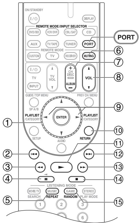
Press [PORT] button first
Note:
For detailed operation of the iPod, please refer to the instruction manual.
① Arrow [] / [] and ENTER buttons
Used to navigate menus and select items.
② Previous [1] button
Restarts the current song. Press it twice to select the previous song.
③ Rewind [←] button
Press and hold to rewind.
④ Pause [I] button
Pauses playback.
⑤ REPEAT button
Used with the repeat function.
⑥ MUTING button (45)
Mutes or unmutes the AV receiver.
⑦ ALBUM +/- button
Selects the next or previous album.
⑧ VOL [] / [] button (44)
Adjusts the volume of the AV receiver.
⑨ PLAYLIST[<]/[▶]buttons
Selects the previous or next playlist on the iPod.
RETURN button
Exits the menu or returns to the previous menu.
⑪ Play [▶] button
Starts playback. If the component is off, it will turn on automatically.
⑫ Next [▶i] button
Selects the next song.
⑬ Fast Forward [▶▶] button
Press and hold to fast forward.
⑭ Stop [■] button
Stops playback and displays a menu.
15 RANDOM button
Used with the shuffle function.
Status messages
Note:
In case of a transmission error without a status message appearing in the front panel, check the connection to your iPod.
Dock in connection with the check
PORT Reading
This unit is in the middle of recognizing the connection with your iPod.
This unit is in the middle of acquiring song lists from your iPod.
Dock does not support the control
PORT Not Supported
The iPod being used is not supported by this unit.
UP-A1L is connected
PORT UP-H1
Your iPod is properly stationed in a UP-A1L Dock connected to the PORT jack of this unit, and the connection between your iPod and this unit is complete. When connection is confirmed, "UP-A1" is displayed for about 8 seconds.
UP-A1L is not connected
FORT
Your iPod was removed from a UP-A1L Dock connected to the PORT jack of this unit.
- Station your iPod back in a UP-A1L Dock connected to the PORT jack of this unit.
This section explains how to record the input source and how to record audio and video from separate sources.
Notes:
- The surround sound and DSP listening modes cannot be recorded.
- Copy-protected DVDs cannot be recorded.
- Sources connected to a digital input cannot be recorded. Only analog inputs can be recorded.
- DTS signals will be recorded as noise, so don't attempt analog recording of DTS CDs or LDs.
Recording the Input Source
Audio sources can be recorded to a recorder (e.g., cassette deck, CDR, MD) connected to the TV/TAPE OUT jack. Video sources can be recorded to a video recorder (e.g., VCR, DVR) connected to the VCR/DVR OUT jacks. See pages 24 to 37 for hookup information.
| 1 DVD/VO AUX CD 2 | VCR/DVR TV/Tape PORT | CBL/SA TUNER MASTER VOLUME control has no effect on recording. | Use the input selector buttons to select the source that you want to record. You can watch the source while recording it. The AV receiver's MASTER VOLUME control has no effect on recording. |
| 3 | On your recorder, start recording. | ||
| 3 | On the source component, start playback. |
Note:
If you select a different input source during recording, that input source will be recorded instead.
Recording from Different AV Sources
You can overdub audio onto your video recordings by simultaneously recording audio and video from two separate sources. This is possible because only the audio source is switched when an audio-only input source, such as TV/TAPE or CD, is selected, the video source remains the same.
In the following example, audio from the CD player connected to the CD IN and video from the camcorder connected to the AUX INPUT VIDEO jack are recorded by the VCR connected to the VCR/DVR OUT jacks.
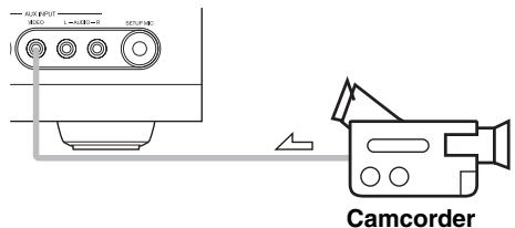
: video signal
:audio signal
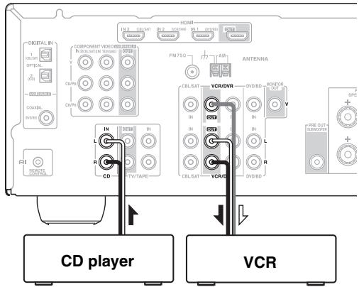
| 1 | Prepare the camcorder and CD player for playback. |
| 2 | Prepare the VCR for recording. |
| 3 | Press the [AUX] input selector button. |
| 4 | Press the [CD] input selector button. This selects the CD player as the audio source but leaves the camcorder as the video source. |
| 5 | Start recording on the VCR, then start playback on the camcorder and CD player. Video from the camcorder and audio from the CD player are recorded by the VCR. |
Selecting the Listening Modes
For a description of each listening mode, see "About the Listening Modes" on page 68.
- The Dolby Digital and DTS listening modes can only be selected if your DVD/BD player is connected to the AV receiver with a digital audio connection (OPTICAL, or COAXIAL).
- The listening modes you can select depends on the format of the input signal. To check the format, see "Displaying Source Information" on page 46.
- While a pair of headphones is connected, you can only select the Mono, Direct, or Stereo listening mode.
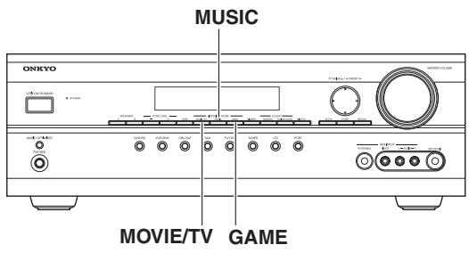
Selecting on the AV receiver
LISTENING MODE buttons
[MOVIE/TV] button
This button selects the listening modes intended for use with movies and TV.
[MUSIC] button
This button selects the listening modes intended for use with music.
[GAME] button
This button selects the listening modes intended for use with video games.
![ONKYO UP-A1L - [GAME] button - 1](/content/2025/01/151778/images/6f71d1c5de282d27ed14e6d04f2ddccd506249cc54776093ff0e845315f719ff.jpg)
Selecting with the Remote Controller
![ONKYO UP-A1L - [GAME] button - 2](/content/2025/01/151778/images/a8fef174444a633b9a821864b740400e88b47f5a35555962cffef219881320bd.jpg)
Press the [RECEIVER] button, and then press the LISTENING MODE button repeatedly to select the listening mode.
LISTENING MODE buttons
[MOVIE/TV] button
This button selects the listening modes intended for use with movies and TV.
[MUSIC] button
This button selects the listening modes intended for use with music.
[GAME] button
This button selects the listening modes intended for use with video games.
[STEREO] button
This button selects the Stereo listening mode and All Channel Stereo listening mode.
Listening Modes Available for Each Source Format
The Speaker layout illustration shows which speakers are set to active in the "Sp Config" setting (see page 70).
The LISTENING MODE button illustration shows that listening modes can be selected.
MOVIE/TV
MUSIC
GAME
STEREO
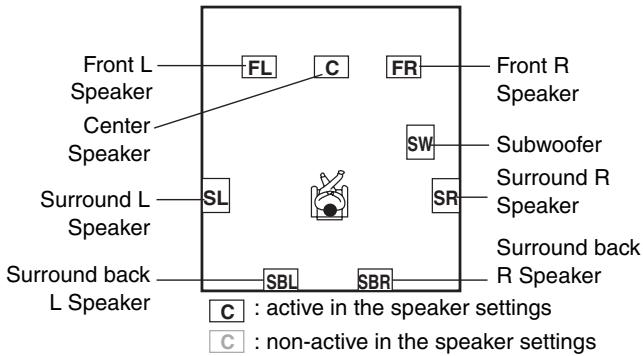
Mono/Multiplex Sources
: Available Listening Modes
| Listening Mode | Button | Speaker layout | |||||
| FL C FR SW SL SRL SBL SBR | FL C FR SW SL SRL SBL SBR | FL C FR SW SL SRL SBL SBR | FL C FR SW SL SRL SBR SBL SBR | FL C FR SW SL SRL SBL SBR | |||
| Direct | MOVETV MUSIC GAME | ✓ | ✓ | ✓ | ✓ | ✓ | |
| Stereo | STEREO MUSIC | ✓ | ✓ | ✓ | ✓ | ✓ | |
| Mono | MOVETV | ✓ | ✓ | ✓ | ✓ | ✓ | |
| Orchestra | MUSIC | ✓ | ✓ | ✓ | |||
| Unplugged | MUSIC | ✓ | ✓ | ✓ | |||
| Studio-Mix | MUSIC | ✓ | ✓ | ✓ | |||
| TV Logic | MOVETV | ✓ | ✓ | ✓ | |||
| Game-RPG | GAME | ✓ | ✓ | ✓ | |||
| Game-Action | GAME | ✓ | ✓ | ✓ | |||
| Game-Rock | GAME | ✓ | ✓ | ✓ | |||
| Game-Sports | GAME | ✓ | ✓ | ✓ | |||
| AllChStereo | MOVETV MUSIC GAME STEREO | ✓ | ✓ | ✓ | ✓ | ||
| FullMono | MOVETV MUSIC GAME | ✓ | ✓ | ✓ | ✓ | ||
| T-D (Theater-dimensional) | MOVETV GAME | ✓ | ✓ | ✓ | ✓ | ✓ | |
Notes:
Available sampling rate for PCM input signal is 32/44.1/48/88.2/96kHz.
- The listening modes cannot be selected with some source formats.
Stereo Source
: Available Listening Modes
| Listening Mode | Button | Speaker layout | ||||
| FL C FR SW SL SR SBL SBR | FL C FR SW SL SR SBL SBR | FL C FR SW SL SR SBL SBR | FL C FR SW SL SR SBL SBR | FL C FR SW SL SR SBL SBR | ||
| Direct | MOVETV MUSIC GAME | ✓ | ✓ | ✓ | ✓ | ✓ |
| Stereo | STEREO MUSIC | ✓ | ✓ | ✓ | ✓ | ✓ |
| Mono | MOVETV | ✓ | ✓ | ✓ | ✓ | ✓ |
| PLII/PLIIx Movie | MOVETV | ✓+1 | ✓+1 | ✓+1 | ✓ | ✓ |
| PLII/PLIIx Music | MUSIC | ✓+1 | ✓+1 | ✓+1 | ✓ | ✓ |
| PLII/PLIIx Game | GAME | ✓+1 | ✓+1 | ✓+1 | ✓ | ✓ |
| Neo:6 Cinema | MOVETV | ✓ | ✓ | ✓ | ✓ | |
| Neo:6 Music | MUSIC | ✓ | ✓ | ✓ | ✓ | |
| Orchestra | MUSIC | ✓ | ✓ | ✓ | ||
| Unplugged | MUSIC | ✓ | ✓ | ✓ | ||
| Studio-Mix | MUSIC | ✓ | ✓ | ✓ | ||
| TV Logic | MOVETV | ✓ | ✓ | ✓ | ||
| Game-RPG | GAME | ✓ | ✓ | ✓ | ||
| Game-Action | GAME | ✓ | ✓ | ✓ | ||
| Game-Rock | GAME | ✓ | ✓ | ✓ | ||
| Game-Sports | GAME | ✓ | ✓ | ✓ | ||
| AllChStereo | MOVETV MUSIC GAME STEREO | ✓ | ✓ | ✓ | ✓ | |
| FullMono | MOVETV MUSIC GAME | ✓ | ✓ | ✓ | ✓ | |
| T-D (Theater-dimensional) | MOVETV GAME | ✓ | ✓ | ✓ | ✓ | ✓ |
Notes:
*1 If there are no surround back speakers, or speaker set B is on, Dolby Pro Logic II is used.
- Available sampling rate for PCM input signal is 32/44.1/48/88.2/96kHz.
- The listening modes cannot be selected with some source formats.
5.1 channel Sources
: Available Listening Modes
| Listening Mode | Button | Speaker layout | |||||
| FL C FR SW SL SR SBL SBR | FL C FR SW SL SR SBL SBR | FL C FR SW SL SR SBL SBR | FL C FR SW SL SR SBL SBR | FL C FR SW SL SR SBL SBR | |||
| Direct | MOVE/TV MUSIC GAME | ✓ | ✓ | ✓ | ✓ | ✓ | |
| Stereo | STEREO MUSIC | ✓ | ✓ | ✓ | ✓ | ✓ | |
| Mono | MOVE/TV | ✓ | ✓ | ✓ | ✓ | ✓ | |
| DolbyDigital/DTS | MOVE/TV MUSIC GAME | ✓ | ✓ | ✓ | ✓ | ||
| Neo:6 | MOVE/TV MUSIC GAME | ✓ | |||||
| PLIIx Movie | MOVE/TV | ✓ | |||||
| PLIIx Music | MUSIC | ✓ | |||||
| DolbyEX | MOVE/TV MUSIC GAME | ✓ | |||||
| Orchestra | MUSIC | ✓ | ✓ | ✓ | |||
| Unplugged | MUSIC | ✓ | ✓ | ✓ | |||
| Studio-Mix | MUSIC | ✓ | ✓ | ✓ | |||
| TV Logic | MOVE/TV | ✓ | ✓ | ✓ | |||
| Game-RPG | GAME | ✓ | ✓ | ✓ | |||
| Game-Action | GAME | ✓ | ✓ | ✓ | |||
| Game-Rock | GAME | ✓ | ✓ | ✓ | |||
| Game-Sports | GAME | ✓ | ✓ | ✓ | |||
| AllChStereo | MOVE/TV MUSIC GAME STEREO | ✓ | ✓ | ✓ | ✓ | ||
| FullMono | MOVE/TV MUSIC GAME | ✓ | ✓ | ✓ | ✓ | ||
| T-D(Theater-dimensional) | MOVE/TV GAME | ✓ | ✓ | ✓ | ✓ | ✓ | |
DTS-ES Discrete/Matrix Sources
| DTS-ES Discrete | MOVETV MUSIC GAME | ✓ | |||
| DTS-ES Matrix | MOVETV MUSIC GAME | ✓ |
Notes:
Available sampling rate for PCM input signal is 32/44.1/48/88.2/96kHz.
- The listening modes cannot be selected with some source formats.
About the Listening Modes
The AV receiver's listening modes can transform your listening room into a movie theater or concert hall, with high fidelity and stunning surround sound.
Direct
In this mode, audio from the input source is output directly with minimal processing, providing high-fidelity reproduction. All of the source's audio channels are output as they are.
Stereo
Sound is output by the front left and right speakers and subwoofer.
Mono
Use this mode when watching an old movie with a mono soundtrack, or use it with the foreign language soundtracks recorded in the left and right channels of some movies. It can also be used with DVDs or other sources containing multiplexed audio, such as karaoke DVDs.
Dolby Pro Logic IIx
Dolby Pro Logic II
Dolby Pro Logic IIx expands any 2-channel source for 7.1-channel playback. It provides a very natural and seamless surround-sound experience that fully envelops the listener. As well as music and movies, video games can also benefit from the dramatic spatial effects and vivid imaging. If you're not using any surround back speakers, Dolby Pro Logic II will be used instead of Dolby Pro Logic IIx.
- Dolby PLIIx Movie
Use this mode with any stereo or Dolby Surround (Pro Logic) movie (e.g., TV, DVD, VHS).
- Dolby PLIIx Music
Use this mode with any stereo or Dolby Surround (Pro Logic) music source (e.g., CD, radio, cassette, TV, VHS, DVD).
- Dolby PLIIx Game
Use this mode with video games, especially those that bear the Dolby Pro Logic II logo.
Dolby Digital
Use this mode with DVDs that bear the Dolby Digital logo, and Dolby Digital TV broadcasts. This is the most common digital surround-sound format, and it'll put you right in the middle of the action, just like being in a movie theater or concert hall.
5.1-channel source + Dolby EX
These modes expand 5.1-channel sources for 6.1/7.1-channel playback. They're especially suited to Dolby EX soundtracks that include a matrix-encoded surround back channel. The additional channel adds an extra dimension and provides an enveloping surround sound experience, perfect for rotating and fly-by sound effects.
5.1-channel source + Dolby PLIIx Music
These modes use the Dolby Pro Logic IIx Music mode to expand 5.1-channel sources for 6.1/7.1-channel playback.
5.1-channel source + Dolby PLIIx Movie
These modes use the Dolby Pro Logic IIx Movie mode to expand 5.1-channel sources for 7.1-channel playback.
DTS
The DTS digital surround-sound format supports up to 5.1 discrete channels and uses less compression for high-fidelity reproduction. Use it with DVDs and CDs that bear the DTS logo.
DTS 96/24
This mode is for use with DTS 96/24 sources. This is high-resolution DTS with a 96kHz sampling rate and 24-bit resolution, providing superior fidelity. Use it with DVDs that bear the DTS 96/24 logo.
DTS-ES Discrete
This mode is for use with DTS-ES Discrete soundtracks, which use a discrete surround back channel for true 6.1/7.1-channel playback. The seven totally separate audio channels provide better spatial imaging and 360-degree sound localization, perfect for sounds that pan across the surround channels. Use it with DVDs that bear the DTS-ES logo, especially those with a DTS-ES Discrete soundtrack.
DTS-ES Matrix
This mode is for use with DTS-ES Matrix soundtracks, which use a matrix-encoded back-channel for 6.1/7.1-channel playback. Use it with DVDs that bear the DTS-ES logo, especially those with a DTS-ES Matrix soundtrack.
DTS Neo:6
This mode expands any 2-channel source for up to 7.1-channel playback. It uses seven full-bandwidth channels of matrix decoding for matrix-encoded material, providing a very natural and seamless surround sound experience that fully envelops the listener.
Neo:6 Cinema
Use this mode with any stereo movie (e.g., TV, DVD, VHS).
Neo:6 Music
Use this mode with any stereo music source (e.g., CD, radio, cassette, TV, VHS, DVD).
5.1-channel source + Neo:6
This mode uses Neo:6 to expand 5.1-channel sources for 6.1/7.1-channel playback.
Onkyo Original DSP Modes
Orchestra
Suitable for classical or operatic music, this mode emphasizes the surround channels in order to widen the stereo image, and simulates the natural reverberation of a large hall.
Unplugged
Suitable for acoustic instruments, vocals, and jazz, this mode emphasizes the front stereo image, giving the impression of being right in front of the stage.
Studio-Mix
Suitable for rock or pop music, listening to music in this mode creates a lively sound field with a powerful acoustic image, like being at a club or rock concert.
TV Logic
This mode adds realistic acoustics to TV shows produced in a TV studio, surround effects to the entire sound, and clarity to voices.
Game-RPG
Use this mode when playing role playing game discs.
Game-Action
Use this mode when playing action game discs.
Game-Rock
Use this mode when playing rock game discs.
Game-Sports
Use this mode when playing sports game discs.
All Ch Stereo
Ideal for background music, this mode fills the entire listening area with stereo sound from the front, surround, and surround back speakers.
Full Mono
In this mode, all speakers output the same sound in mono, so the sound you hear is the same regardless of where you are within the listening room.
T-D (Theater-Dimensional)
With this mode you can enjoy a virtual surround sound even with only two or three speakers. This works by controlling how sounds reach the listener's left and right ears. Good results may not be possible if there's too much reverb, so we recommend that you use this mode in an environment with little or no natural reverb.
Common Procedures in Setup Menu
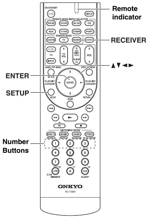
Press the [RECEIVER] button followed by the [SETUP] button.
2 Use the Up and Down [] / [] buttons to select the function, and then press the [ENTER] button.
3 Use the Up and Down [] / [] button to select item, and then use the Left and Right [] / [] buttons to set them.
4 When you've finished, press the [SETUP] button. Setup closes.
Note:
This procedure can also be performed on the AV receiver by using its [SETUP] button, arrow buttons, and [ENTER] button.
Speaker Settings
This section explains how to check the speaker settings and how to set them manually, which is useful if you change a speaker after performing the Audyssey 2EQTM Room Correction and Speaker Setup.
Some of the speaker settings are set automatically by the Audyssey 2EQ Room Correction and Speaker Setup function (see page 39).
3. Sp Config (Speaker Configuration)
These settings are set automatically by the Audyssey 2EQ Room Correction and Speaker Setup function (see page 39).
This section explains how to specify which speakers are connected and their sizes.
For speakers with a cone diameter larger than 6-1/2 inches (16 cm), specify Large (full band). For those with a smaller diameter, specify Small (default crossover 150Hz ).
The crossover frequency can be changed on page 71.
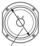
Core diameter
Note:
These settings cannot be changed while a pair of headphones is connected, or speaker set A is off, or speaker set B is on, or the AV receiver is muted.
| Subwoofer | Yes: | Select if a subwoofer is connected (default). |
| No: | Select if no subwoofer is connected. | |
| Front*1 | Small: | Select if the front speakers are small (default). |
| Large: | Select if the front speakers are large. | |
| Center*2 | Small: | Select if the center speaker is small (default). |
| Large: | Select if the center speaker is large. | |
| None: | Select if no center speaker is connected. | |
| Surround*2 | Small: | Select if the surround speakers are small (default). |
| Large: | Select if the surround speakers are large. | |
| None: | Select if no surround speakers are connected. |
1 If the "Subwoofer" setting is set to "No", this setting is fixed at "Large" and does not appear.
2 If the "Front" setting is set to "Small", the "Large" option cannot be selected.
SurrBack\*3\*4
Small: Select if the surround back speakers are small (default).
Large: Select if the surround back speakers are large.
None: Select if no surround back speakers are connected.
SurrBack Ch*5
2ch: Select if two (left and right) surround back speakers are connected.
1ch: Select if only one surround back L speaker is connected.
3 If the "Surround" setting is set to "None", this setting does not appear.
4 If the "Surround" setting is set to "Small", the Large option cannot be selected.
*5 If the "Surround" or "SurrBack" settings are set to "None", this setting does not appear.
Crossover (Crossover Frequency)
This setting is set automatically by the Audyssey 2EQ^TM Room Correction and Speaker Setup function (see page 39).
This setting only applies to the speakers that you specified as "Small" in the "3. Sp Config" on page 70.
To get the best bass performance from your speaker system, you need to set the crossover frequency according to the size and frequency response of your speakers.
Use the diameter of the smallest speaker in your system when choosing the crossover frequency.
| Speaker cone diameter | Crossover frequency |
| Over 8 in. (20 cm) | 40/50/60Hz* |
| 6-1/2 to 8 in. (16–20 cm) | 80Hz |
| 5-1/4 to 6-1/2 in. (13–16 cm) | 100Hz (default) |
| 3-1/2 to 5-1/4 in. (9–13 cm) | 120Hz |
| Under 3-1/2 in. (9 cm) | 150 /200Hz* |
- Choose the setting suitable for the speaker.
Notes:
- For a more accurate setting, look up the frequency response in the manuals supplied with your speakers and set accordingly.
- Choose a higher crossover frequency if you want more sound from your subwoofer.
Double Bass
This setting is not set automatically by the Audyssey 2EQ Room Correction and Speaker Setup function (see page 39).
With the Double Bass function, you can boost bass output by feeding bass sounds from the front left, right, and center to the subwoofer. This function can be set only if the "Subwoofer" setting is set to "Yes", and the "Front" setting is set to "Large" in the "3. Sp Config" on page 70.
On: Double Bass function on. Bass from the front left and right channels is also fed to the subwoofer (default).
Off: Double Bass function off.
4. Sp Distance (Speaker Distance)
These settings are set automatically by the Audyssey 2EQ Room Correction and Speaker Setup function (see page 39).
With these settings, you can specify the distance from each speaker to the listening position.
Measure and make a note of the distance from each speaker to the listening position.
Notes:
- Speakers that you set to "No" or "None" in the "3. Sp Config" (page 70) cannot be selected.
- These settings cannot be changed while a pair of headphones is connected, or speaker set A is off, or speaker set B is on, or the AV receiver is muted.
- The Center and Subwoofer distances can be set up to 5 ft. (1.5 m) more or less than the Left distance. For example, if the Left distance is set to 20 ft. (6 m), the Center and Subwoofer distances can be set between 15 and 25 ft. (4.5 and 7.5 m).
- The Surround distances can be set up to 5 ft. (1.5 m) more or 15 ft. (4.5 m) less than the Left distance. For example, if the Left distance is set to 20 ft. (6 m), the SurrRight and SurrLeft distances can be set between 5 and 25 ft. (1.5 and 7.5 m).
Unit
feet: Distances can be set in feet. Range: 1 to 30 feet in 1-foot steps.
meters: Distances can be set in meters. Range: 0.3 to 9 meters in 0.3-meter steps.
Front, Center, SurrRight, SurrBack Right, SurrBack Left, SurrLeft, Subwoofer
Specify the distance from the each speaker to your listening position.
5. Level Cal (Speaker Levels Calibration)
These settings are set automatically by the Audyssey 2EQ^TM Room Correction and Speaker Setup function (see page 39).
You can set the volume level of each speaker so that all speakers can be heard equally at the listening position. A pink noise test tone is output by the front left speaker.
Notes:
- Speakers that you set to "No" or "None" in the "3. Sp Config" (page 70) do not output the test tone.
- These settings cannot be changed while a pair of headphones is connected, or speaker set A is off, or speaker set B is on, or the AV receiver is muted.
Left, Center, Right, SurrRight, SurrBack Right, SurrBack Left, SurrLeft, Subwoofer
The levels can be adjusted from -12 to +12 dB in 1 dB steps (-15 to +12 dB for the subwoofer).
6. Equalizer (Equalizer Settings)
These settings are set automatically by the Audyssey 2EQ Room Correction and Speaker Setup function (see page 39). Here you can adjust the tone of individual speakers. To set the volume of individual speakers, see page 72.
Notes:
- You can select: "63Hz", "250Hz", "1000Hz", "4000Hz", or "16000Hz". And for the subwoofer, "25Hz", "40Hz", "63Hz", "100Hz", or "160Hz".
- While the Direct listening mode is selected, the equalizer settings have no effect.
- The equalizer setting cannot be changed while a pair of headphones is connected, or speaker set B is on.
EQ
Manual:
You can adjust the equalizer for each speaker manually. If you select "Manual", continue with this procedure.
Select a frequency
1 Use the Down [▼] button to select "Ch", and then use the Left and Right [▲]/[▶] buttons to select a speaker.
2 Use the Up and Down [] / [] buttons to select a frequency. Use the Left and Right [] / [] buttons to adjust the level at that frequency.
F 250Hz +3dB
The volume at each frequency can be adjusted from -6 to +6dB in 1 dB steps.
Tip:
Low frequencies (e.g., 63Hz ) affect bass sounds; high frequencies (e.g., 16000Hz ) affect treble sounds.
3 Use the Up [▲] button to select "Ch", and then use the Left and Right [▲]/[▶] buttons to select another speaker.
Repeat steps 1 and 2 for each speaker.
Speakers that you set to "No" or "None" in the "3. Sp Config" (page 70) do not output the test tone.
Audyssey: The tone for each speaker is set automatically by the Audyssey 2EQ Room Correction and Speaker Setup function. Be sure to select this setting after having performed the Room Correction and Speaker Setup. "Dynamic EQ" and "Dyn Vol" become available (see page 74).
Off: Tone off, response flat (default).
Audio Adjust Settings
With the Audio Adjust functions and settings, you can adjust the sound and listening modes as you like.
7. Audio Adjust
Multiplex/Mono Settings
| Input (Mux) | Main: The main channel is output (default). Sub: The sub channel is output. M/S: Both the main and sub channels are output. |
| This setting determines which channel of a stereo multiplex source is out languages with multiplex sources, multilingual TV broadcasts, and so on | |
| Input (Mono) | L+R: Both the left and right channels are output ( L: Only the left channel is output. R: Only the right channel is output. |
This setting determines which channel is output when the Mono listening mode is used with a stereo source.
PLIIx/Neo:6 Music Mode Settings
PLIIx Music (2ch Input)
These settings provide for playing any 2-channel digital source such as Dolby Digital, or 2-channel analog/PCM source in the Dolby PLIIx Music listening mode.
| Panorama | On: Panorama function on. |
| Off: Panorama function off (default). |
With this function, you can broaden the width of the front stereo image when using the Dolby Pro Logic II Music or Dolby Pro Logic IIx Music listening mode.
Dimension -3 to +3 (default: 0)
With this setting, you can move the sound field forward or backward when using the Dolby Pro Logic II Music or Dolby Pro Logic IIx Music listening mode. Lower settings move the sound field forward. Higher settings move it backward.
If the stereo image feels too wide, or there is too much surround sound, move the sound field forward to improve the balance. Conversely, if the stereo image feels like it is in mono, or there is not enough surround sound, move it backward.
Center Width 0 to 7 (default: 3)
from the center speaker when using the Dolby Pro Logic II Music or Dolby Pro Logic IIx Music listening mode. Normally, if you are using a center speaker, the center channel sound is output by only the center speaker. (If you are not using a center speaker, the center channel sound will be distributed to the front left and right speakers to create a phantom center.) This setting controls the front left, right, and center mix, allowing you to adjust the weight of the center channel sound.
Neo:6 Music
Center Image 0 to 5 (default: 2)
The DTS Neo:6 Music listening mode creates 6-channel surround sound from 2-channel (stereo) sources. With this setting, you can specify by how much the front left and right channel output is attenuated in order to create the center channel. This setting is unavailable if no surround speakers are connected.
Setting a value [0] in the middle is set to hear a sound. Sound is spread in left and right (the outside) so that the set value is made big. Please adjust by liking.
Dolby EX Input Signal Setting
Dolby EX
Auto: When the source is Dolby EX, you can select the Dolby EX listening mode.
Manual: When the source is Dolby EX, you can select any of the listening modes compatible with this format (e.g., Dolby EX, Dolby Pro Logic IIx, etc.) (default).
This setting determines how Dolby EX encoded signals are handled. This setting is unavailable if no surround back speakers are connected. This setting is effective with Dolby Digital, Dolby Digital Plus and Dolby TrueHD only.
Audyssey Settings
After room correction and speaker setup is completed, Audyssey Dynamic EQ™ becomes "On" by default.
Dynamic EQ
Off: Audyssey Dynamic EQ off.
On: Audyssey Dynamic EQ on (default).
With Audyssey Dynamic EQ, you can enjoy great sound even when listening at low volume levels.
Audyssey Dynamic EQ solves the problem of deteriorating sound quality as volume is decreased by taking into account human perception and room acoustics. It does so by selecting the correct frequency response and surround volume levels moment-by-moment so that the content sounds the way it was created at any volume level--not just at reference level.
Notes:
- Audyssey Dynamic EQ allows you to maintain the proper octave-to-octave balance at any volume level in accordance with the speakers.
- In order to record with appropriate sound, Audyssey 2EQ^TM is automatically deactivated during a recording. After the recording is finished, Audyssey 2EQ and Audyssey Dynamic EQ will resume as previously set.
- "Dynamic EQ" and "Dyn Vol" become available (see page 74).
Dyn Vol (Dynamic Volume)
Off: Audyssey Dynamic VolumeTM off.
Light: Light Compression Mode becomes active (see page 39).
Medium: Medium Compression Mode becomes active (see page 39).
Heavy: Heavy Compression Mode becomes active. This setting affects volume the most, causing all sounds to be of equal loudness.
Notes:
- Other than "Off", "Dynamic EQ" becomes "On", and "6. Equalizer" (see page 72) setting becomes "Audyssey".
- "Dynamic Volume" becomes active when Dynamic EQ is set to "On". Therefore, it is "Off" forcibly if "Dynamic EQ" becomes "Off".
T-D (Theater-Dimensional) Setting
LstnAngl (Listening Angle)
Wide: Select if the listening angle is 40 degrees (default).
Narrow: Select if the listening angle is 20 degrees.
With this setting, you can optimize the Theater-Dimensional listening mode by specifying the angle of the front left and right speakers relative to the listening position. Ideally, the front left and right speakers should be equidistant from the listening position and at an angle close to one of the two available settings.
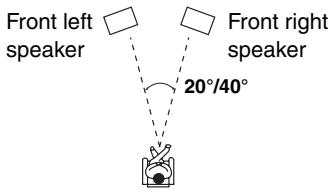
Hardware Setup
This section explains items on the Hardware menu.
8. Hardware
Remote ID
When several Onkyo components are used in the same room, their remote ID codes may overlap. To differentiate the AV receiver from the other components, you can change its remote ID from 1, the default, to 2 or 3.
Remote ID 1,2,3
Note:
If you do change the AV receiver's remote ID, be sure to change the remote controller to the same ID (see below), otherwise, you won't be able to control it with the remote controller.
Changing the Remote Controller's ID
| 1 | While holding down the [RECEIVER] button, press and hold down the [SETUP] button until the Remote indicator lights up (about 3 seconds). |
| 2 | Use the number buttons to enter ID 1, 2, or 3. The Remote indicator flashes twice. |
Tuner
FM/AM
See "AM/FM Frequency Step Setup" on page 48.
SAT Radio
See "Listening to Sattellite Radio" on page 52.
Using the Audio Settings
You can change various audio settings by pressing the [AUDIO] button.
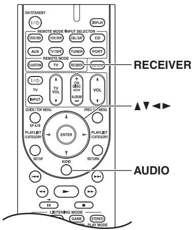
Press the [RECEIVER] button followed by the [AUDIO] button.
2 Use the Up and Down [] / [] buttons to select an item.
3 Use the Left and Right [] / [] buttons to change the setting.
Repeat this step for the other settings.
Tone Control Settings
You can adjust the bass and treble for the front speakers, except when the Direct listening mode is selected.
Notes:
- To bypass the bass and treble tone circuits, select the Direct listening mode.
- This procedure can also be performed on the AV receiver by using its [TONE], [-] , and [+] buttons.
Bass
-10dB to +10dB in 2dB steps (default: 0dB)
Treble
-10dB to +10dB in 2dB steps (default: 0dB)
Late Night Function
With the Late Night function, you can reduce the dynamic range of Dolby Digital material so that you can still hear quiet parts even when listening at low volume levels—ideal for watching movies late at night when you don't want to disturb anyone.
Notes:
- The Late Night function can be used only when the input source is Dolby Digital.
- The effect of the Late Night function depends on the material that you are playing and the intention of the original sound designer, and with some material there will be little or no effect when you select the different options.
- The Late Night function is set to Off when the AV receiver is set to Standby.
Late Night
Off: Late Night function off (default).
Low: Small reduction in dynamic range.
High: Large reduction in dynamic range.
CinemaFILTER
With the CinemaFILTER, you can soften overly bright movie soundtracks, which are typically mixed for reproduction in a movie theater.
CinemaFILTER can be used with the following listening modes: Dolby Digital, Dolby Digital EX, Dolby Pro Logic IIx Movie, Dolby Pro Logic II Movie, DTS, DTSES, DTS Neo:6 Cinema, DTS 96/24, and Neo:6.
Note:
The CinemaFILTER may not work when used with certain input sources.
Cinema Fltr
Off: CinemaFILTER off (default).
On: CinemaFILTER on.
Audyssey Dynamic Volume™
Dyn Vol
See "Dyn Vol" of "Audio Adjust Settings" on page 74.
Music Optimizer
The Music Optimizer function enhances the sound quality of compressed music files. Use it with music files that use "lossy" compression, such as MP3.
Note:
The Music Optimizer function only works with PCM digital audio input signals with a sampling rate below 48kHz and analog audio input signals. The Music Optimizer is disabled when the Direct listening mode is selected.
M.Optimizer
Off: Music Optimizer off (default).
On: Music Optimizer on.
Speaker Levels
You can adjust the volume of each speaker while listening to an input source.
These temporary adjustments are cancelled when the AV receiver is set to Standby.
Notes:
- You cannot use this function while the AV receiver is muted.
- Speakers that are set to "No" or "None" in the "3. Sp Config" cannot be adjusted (see page 70).
SW Level (Subwoofer)
-15dB to +12dB (default: 0dB)
C Level (Center)
-12dB to +12dB (default: 0dB)
A/V Sync
When using progressive scanning on your DVD player, you may find that the picture and sound are out of sync. With this setting, you can correct this by delaying the audio signals.
Notes:
- This setting is not available when the Direct listening mode is used with an analog input signal.
- The setting is stored individually for each input selector.
A/V Sync
0ms to 100ms in 20ms steps
You can control your DVD player, CD player, and other components with the AV receiver's remote controller.
To control another component, you must first enter that component's remote control code to a REMOTE MODE button.
This section explains how to enter remote control codes and how to control your other components.
Preprogrammed Remote Control Codes
The following REMOTE MODE buttons are preprogrammed with remote control codes for controlling the components listed. You do not need to enter a remote control code to control these components. For details on controlling these components, see the pages indicated.

Onkyo DVD/BD player (page 80)

Onkyo CD player (page 81)

Onkyo cassette recorder with R1 (page 82)

Onkyo Dock (pages 61, 83)
Entering Remote Control Codes
You'll need to enter a code for each component that you want to control.
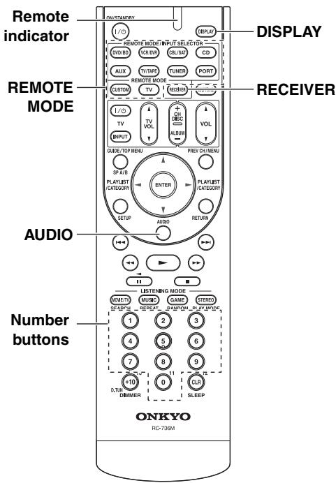
1
Look up the appropriate remote control code in the separate Remote Control Codes list.
The codes are organized by category (e.g., DVD player, TV, etc.).
2
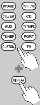
(3 seconds)
While holding down the REMOTE MODE button to which you want to enter a code, press and hold down the [DISPLAY] button until the Remote indicator lights up (about 3 seconds).
Note:
- Remote control codes cannot be entered for the [RECEIVER] button.
- Only TV remote control codes can be entered for the [TV] button.
- Apart from the [RECEIVER], [TV] buttons, remote control codes from any category can be entered for the REMOTE MODE buttons. However, these buttons also work as input selector buttons (page 44), so choose a REMOTE MODE button that corresponds with the input to which you connect your component. For example, if you connect your CD player to the CD input, choose the [CD] button when entering its remote control code.
3

Within 30 seconds, use the number buttons to enter the 5-digit remote control code.
The Remote indicator flashes twice. If the remote control code is not entered successfully, the Remote indicator will flash once slowly.
Note:
The remote control codes provided are correct at the time of printing but subject to change.
Remote Control Codes for Onkyo Components Connected via RI
Onkyo components that are connected via RI are controlled by pointing the remote controller at the AV receiver, not the component. This allows you to control components that are out of view, in a rack, for example.
1 Make sure the Onkyo component is connected with an RI cable and an analog audio cable (RCA).
See page 37 for details.
2 Enter the appropriate remote control code to the REMOTE MODE button.
- [DVD/BD] button
31612: Onkyo DVD player with Rl
- [CD] button
71327: Onkyo CD player with Rl
- [TV/TAPE] button
42157: Onkyo cassette recorder with RI (default)
- [PORT] button
82351: Onkyo Dock
[TUNER] button
51805: To control the AV receiver's tune (default)
See the previous page for how to enter remote control codes.
3 Press the REMOTE MODE button, point the remote controller at the AV receiver, and operate the component.
If you want to control an Onkyo component by pointing the remote controller directly at it, or you want to control an Onkyo component that's not connected via RI, use the following remote control codes:
- [DVD/BD] button
30627: Onkyo DVD player without Rl (default)
- [CD] button
71817: Onkyo CD player without RI (default)
- [TV] button
11807: Onkyo TV (default)
If you want to control an Onkyo component by pointing the remote controller directly at it, use the following remote control codes:
32900: Onkyo BD player
32901: Onkyo HD-DVD player
70868: Onkyo MD player
71323: Onkyo CD recorder
82990: Onkyo RI Dock
Note:
If you connect an RI-capable Onkyo MiniDisc recorder, CD recorder, or RI Dock to the TV/TAPE IN/OUT jacks, or connect an RI Dock to the CBL/SAT IN or VCR/DVR IN jacks, for RI to work properly, you must set the Input Display accordingly (see page 43).
Resetting the REMOTE MODE Buttons
You can reset a REMOTE MODE button to its default remote control code.
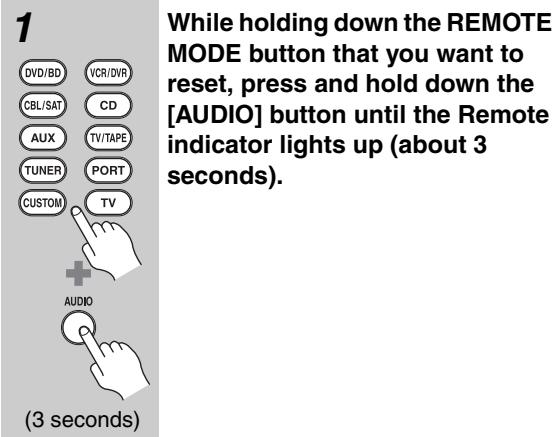
2 Within 30 seconds, press the REMOTE MODE button again.
The Remote indicator flashes twice, indicating that the button has been reset.
Each of the REMOTE MODE buttons is preprogrammed with a remote control code. When a button is reset, its preprogrammed code is restored.
Resetting the Remote Controller
You can reset the remote controller to its default settings.
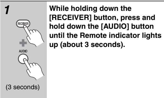
2 Within 30 seconds, press the [RECEIVER] button again.
The Remote indicator flashes twice, indicating that the remote controller has been reset.
Controlling a DVD Player, or DVD Recorder
By pressing the REMOTE MODE button that's been programmed with the remote control code for your DVD player (HD DVD, Blu-ray, or TV/DVD combination), you can control your player with the following buttons.
The [DVD/BD] button is preprogrammed with the remote control code for controlling an Onkyo DVD player.
For details on entering a remote control code for a different component, see page 78.
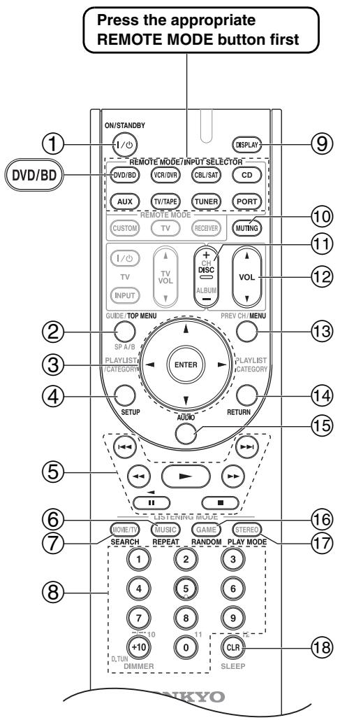
① ON/STANDBY button
Sets the DVD player to On or Standby.
② TOP MENU button
Displays a DVD's top menu or a DVD's title.
③ Arrow [▲]/[▼]/[▲]/[▶] and ENTER buttons
Used to navigate menus and select items.
④ SETUP button
Used to access the DVD player's settings.
⑤ Playback buttons
Play [▶], Pause [■], Stop [■], Fast Reverse [▲], Fast forward [▶], Previous [I<], and Next [▶].
⑥ REPEAT button
Used with the repeat playback function.
⑦ SEARCH button
Used to search title, chapter, and track numbers, and to search times for locating specific points.
⑧ Number buttons
Used to enter title, chapter, and track numbers, and to enter times for locating specific points. The [+10] button works as a +10 button or "---" button.
⑨ DISPLAY button
Displays information about the current disc, title, chapter, or track, including elapsed time, remaining time, total time, and so on.
10 MUTING button (45)
Mutes or unmutes the AV receiver.
⑪ DISC +/- button
Selects discs on a DVD changer.
⑫ VOL [▲]/[▼] button (44)
Adjusts the volume of the AV receiver.
13 MENU button
Displays a DVD's menu.
14 RETURN button
Expires the DVD player's setup menu or returns to the previous menu.
15 AUDIO button
Selects foreign language soundtracks and audio formats (e.g., Dolby Digital or DTS).
16 RANDOM button
Used with the random playback function.
⑦ PLAY MODE button
Selects play modes on components with selectable play modes.
18 CLR button
Cancels functions and clears entered numbers.
Notes:
-
With some components, certain buttons may not work as expected, and some may not work at all.
-
If you enter the remote control code for a Blu-ray or HD DVD player that has A, B, C, and D or colored buttons, the [SEARCH], [REPEAT], [RANDOM], and [PLAY MODE] buttons will work as colored or A, B, C, D buttons. In this case, these buttons cannot be used to set repeat playback, random playback, or select play modes.
Controlling a CD Player, CD Recorder, or MD Player
By pressing the REMOTE MODE button that's been programmed with the remote control code for your CD player, CD recorder, or MD player, you can control your player with the following buttons.
The [CD] button is preprogrammed with the remote control code for controlling an Onkyo CD player.
For details on entering a remote control code for a different component, see page 78.
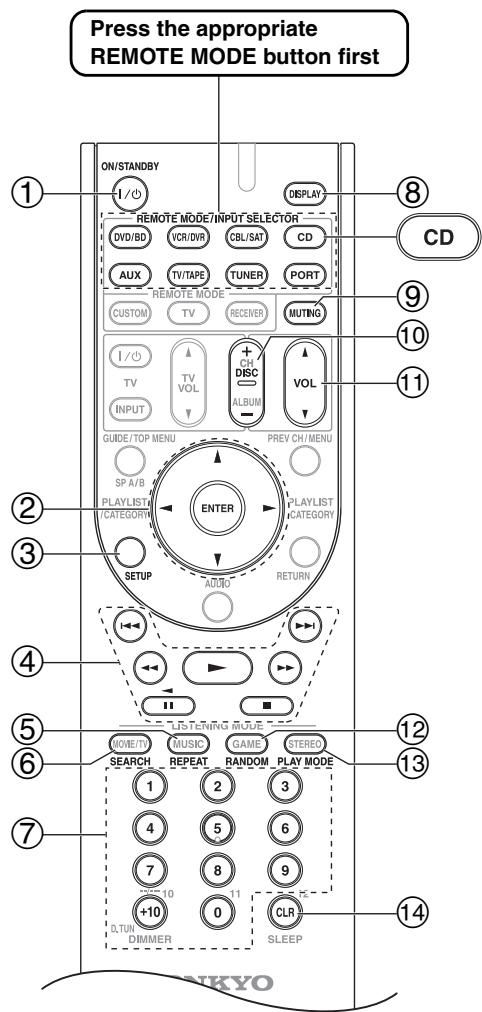
① ON/STANDBY button
Set the component to On or Standby.
② Arrow [▲]/[▼]/[▲]/[▶] and ENTER buttons
Used to navigate menus and select items.
③ SETUP button
Used to access the Onkyo CD player's settings.
④ Playback buttons
Play [▶], Pause [■], Stop [■], Fast Reverse [▲], Fast forward [▶], Previous [■], and Next [▶].
⑤ REPEAT button
Used with the repeat playback function.
⑥ SEARCH button
Used to locate specific points.
⑦ Number buttons
Used to enter track numbers and times for locating specific points. The [+10] button works as a +10 button or "---" button.
⑧ DISPLAY button
Displays information about the current disc or track, including elapsed time, remaining time, total time, and so on.
⑨ MUTING button (45)
Mutes or unmutes the AV receiver.
10 DISC + / - button
Selects discs on a CD changer.
① VOL [] / [] button (44)
Adjusts the volume of the AV receiver.
12 RANDOM button
Used with the random playback function.
13 PLAY MODE button
Selects play modes on components with selectable play modes.
14 CLR button
Cancels functions and clears entered numbers.
Note:
With some components, certain buttons may not work as expected, and some may not work at all.
Controlling a Cassette Recorder
By pressing the REMOTE MODE button that's been programmed with the remote control code for your cassette recorder, you can control your cassette recorder with the following buttons.
The [TV/TAPE] button is preprogrammed with the remote control code for controlling an Onkyo cassette recorder when used with an RI connection.
For details on entering a remote control code for a different component, see page 78.
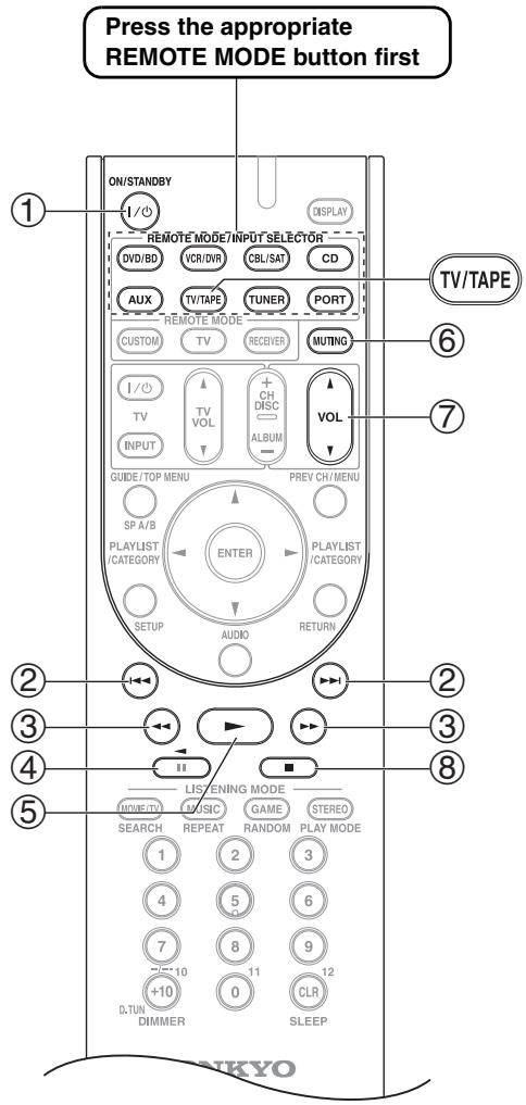
On twin cassette decks, only Deck B can be controlled.
① ON/STANDBY button
Turns the cassette recorder on or off.
② Previous and Next [1 1] / [7 1] buttons
The Previous [I▶] button selects the previous track. During playback it selects the beginning of the current track. The Next [▶▶I] button selects the next track.
Depending on how they were recorded, the Previous and Next [1 1] / [1 1] buttons may not work properly with some cassette tapes.
③ Rewind and Fast Forward [←/][▶] buttons
The Rewind [ ] button starts rewind. The Fast Forward [ ] button starts fast forward.
Starts reverse playback.
⑤ Play [▶] button
Starts playback.
⑥ MUTING button (45)
Mutes or unmutes the AV receiver.
⑦ VOL [] / [] button (44)
Adjusts the volume of the AV receiver.
⑧ Stop [■] button
Stops playback.
Notes:
- With some components, certain buttons may not work as expected, and some may not work at all.
- An Onkyo cassette recorder connected via R1 can also be controlled in Receiver mode.
Controlling an RI Dock
By pressing the REMOTE MODE button that's been programmed with the remote control code for your Dock, you can control your iPod in the Dock with the following buttons.
For some RI docks, the "ON/STANDBY" button may not work with a remote control code 82990 (without RI).
In this case, make an RI connection and enter a remote control code 82351 (with RI ).
For details on entering a remote control code, see page 78.
When Using an RI Dock:
- Connect the RI Dock to the TV/TAPE IN, VCR/DVR IN, or CBL/SAT IN L/R jacks.
- Set the RI Dock's RI MODE switch to "HDD" or "HDD/DOCK".
- Set the AV receiver's Input Display to "DOCK" (see page 43).
See to the Dock's instruction manual for more information.

① ON/STANDBY button
Turns the iPod on or off.
Notes:
-
This button does not turn the Onkyo DS-A2 or DS-A2X RI Dock on or off.
-
Your iPod may not respond the first time you press this button, in which case you should press it again. This is because the remote controller transmits the On and Standby commands alternately, so if your iPod is already on, it will remain on when the remote controller transmits an On command. Similarly, if your iPod is already off, it will remain off when the remote controller transmits an Off command.
② TOP MENU button
Works as a Mode button when used with a DS-A2 RI Dock.
③ Arrow [] / [] and ENTER buttons
Used to navigate menus and select items.
④ Previous [↓←] button
Restarts the current song. Press it twice to select the previous song.
⑤ Rewind [▲] button
Press and hold to rewind.
⑥ Pause [II] button
Pauses playback.
⑦ REPEAT button
Used with the repeat function.
⑧ DISPLAY button
Turns on the backlight for 30 seconds.
⑨ MUTING button (45)
Mutes or unmutes the AV receiver.
10 ALBUM + / - button
Selects the next or previous album.
① VOL [] / [] button (44)
Adjusts the volume of the AV receiver.
12 MENU button
Exits the menu.
13 PLAYLIST[/<]buttons
Selects the previous or next playlist on the iPod.
⑭ Play [▶] button
Starts playback. If the component is off, it will turn on automatically.
15 Next [▶▶i] button
Selects the next song.
16 Fast Forward [▶▶] button
Press and hold to fast forward.
⑦ Stop [■] button
Stops playback and displays a menu.
18 PLAY MODE button
Selects play modes on components with selectable play modes.
Works as a Resume button when used with a DS-A2 RI Dock.
19 RANDOM button
Used with the shuffle function.
Note:
With some components, certain buttons may not work as expected, and some may not work at all.
If you have any trouble using the AV receiver, look for a solution in this section. If you can't resolve the issue yourself, contact your Onkyo dealer.
If you can't resolve the issue yourself, try resetting the AV receiver before contacting your Onkyo dealer.
To reset the AV receiver to its factory defaults, turn it on and, while holding down the [VCR/DVR] button, press the [ON/STANDBY] button. "Clear" will appear on the display and the AV receiver will enter Standby mode.
VCR/DVR
1/ON/STANDBY
Note that resetting the AV receiver will delete your radio presets and custom settings.
Power
Can't turn on the AV receiver
- Make sure that the power cord is plugged into the wall outlet properly.
- Unplug the power cord from the wall outlet, wait 5 seconds or more, then plug it back in again.
The AV receiver turns off as soon as it's turned on
- The amp protection circuit has been activated. Remove the power cord from the wall outlet immediately. Disconnect all speaker cables and input sources, and leave the AV receiver with its power cord disconnected for 1 hour. After that, reconnect the power cord and set the volume to maximum. If the AV receiver stays on, set the volume to minimum, disconnect the power cord, and reconnect your speakers and input sources. If the AV receiver turns off when you set the volume to maximum, disconnect the power cord, and contact your Onkyo dealer.
Audio
There's no sound or it's very quiet.
- Press the SPEAKERS [A] or [B] button to turn on the indicator for the speakers that you want to output sound.
- HDMI audio is passed through the AV receiver and can only be heard from your TV.
- To listen to an audio source that's connected to an OPTICAL or COAXIAL input, make sure that input is assigned to an input selector (page 42).
- Make sure that all audio connecting plugs are pushed in all the way (page 24).
-
Make sure that the polarity of the speaker cables is correct, and that the bare wire is in contact with the metal part of each speaker terminal (page 19).
-
Make sure that the speaker cables are not shorting.
- Check the volume (page 44). The AV receiver is designed for home theater enjoyment and has a wide volume range for precise adjustment.
- If the MUTING indicator is flashing on the display, press the remote controller's [MUTING] button to unmute the AV receiver (page 45).
- While a pair of headphones is connected to the PHONES jack, no sound is output by the speakers (page 46).
- Check the digital audio output settings on the source component. On some game consoles, such as those that can play DVDs, the default setting is off.
- With some DVD-Video discs, you need to select an audio format from a menu or with the [AUDIO] button on your DVD player's remote controller.
- If your turntable doesn't have a phono preamp built-in, you must connect one between it and the AV receiver.
- If your turntable uses an MC cartridge, you must connect an MC head amp, or an MC transformer and a phono preamp.
- Check the speaker settings (pages 70-72).
- If the digital signal format is set to PCM or DTS, set it to "Auto" (page 47).
Only the front speakers produce sound
- When the Stereo or Mono listening mode is selected, only the front speakers and subwoofer produce sound.
- Check the "3. Sp Config" (page 70).
Only the center speaker produces sound
- If you use the Dolby Pro Logic IIx Movie or Dolby Pro Logic IIx Music listening mode with a mono source, such as an AM radio station or mono TV program, the sound will be concentrated in the center speaker.
- Check the "3. Sp Config" (page 70).
The center speaker produces no sound
- When the Stereo or Mono listening mode is selected, the center speaker produces no sound (page 68).
- Check the "3. Sp Config" (page 70).
The surround speakers produce no sound
- When the Stereo or Mono listening mode is selected, the surround speakers produce no sound.
- Depending on the source and the current listening mode, not much sound may be produced by the surround speakers. Try another listening mode (page 64).
- Check the "3. Sp Config" (page 70).
The surround back speakers produce no sound
- The surround back speakers are not used with all listening modes. Try another listening mode (page 64).
- Not much sound may be produced by the surround back speakers with some sources.
- Check the "3. Sp Config" (page 70).
- While speaker set B is on, playback is reduced to 5.1-channels and the surround back speakers produce no sound (page 6).
The subwoofer produces no sound
- The subwoofer outputs no sound while only speaker set B is on. Turn on speaker set A.
- If the source material contains no audio in the LFE channel, the subwoofer produces no sound.
- Check the "3. Sp Config" (page 70).
- On the AV receiver, the subwoofer setting in the "3. Sp Config" is set to "No". Set the subwoofer setting to "Yes".
There's no sound with a certain signal format
- Check the digital audio output setting on the source component. On some game consoles, such as those that can play DVDs, the default setting is off.
- With some DVD-Video discs, you need to select an audio format from a menu or with the [AUDIO] button on your DVD player's remote controller.
Can't get 6.1- or 7.1-channel playback
- While speaker set B is on, playback in the main room is reduced to 5.1-channels and the surround back speakers produce no sound (page 6).
The volume cannot be set to 79
- After the Audyssey 2EQ^TM Room Correction and Speaker Setup function has been run, or the volume level of each individual speaker has been adjusted (pages 39 and 72), the maximum volume may be reduced.
- When the levels of each speaker have been adjusted (page 72), the maximum possible volume may be reduced.
Noise can be heard
- Using cable ties to bundle audio cables with power cords, speaker cables, and so on can degrade audio performance, so don't use them.
- An audio cable may be picking up interference. Try repositioning your cables.
The Late Night function doesn't work
- Make sure that the source is Dolby Digital (page 76).
About DTS signals
- When playing DTS program material, using the pause, fast forward, or fast reverse function on your player may produce a short audible noise. This is not a malfunction.
- When DTS program material ends and the DTS bitstream stops, the AV receiver remains in DTS listening mode and the DTS indicator remains on. This is to prevent noise when you use the pause, fast forward, or fast reverse function on your player. If you switch your player from DTS to PCM, as the AV receiver does not switch formats immediately, you may not hear anything, in which case you should stop your player for about 3 seconds, and then resume playback.
- With some CD players, you won't be able to playback DTS material properly even though your player is connected to a digital input on the AV receiver. This is
usually because the DTS bitstream has been processed (e.g., output level, sampling rate, or frequency response changed) and the AV receiver doesn't recognize it as a genuine DTS signal. In such cases, you may hear noise.
Video
There's no picture
- Make sure that all video connecting plugs are pushed in all the way (page 24).
- Make sure that each video component is properly connected.
- On your TV, make sure that the video input to which the AV receiver is connected is selected.
- The AV receiver does not convert between formats, so if a video source component is connected to a component video input, your TV must be connected to the component video output (page 25).
- If the video source is connected to an HDMI input, your TV must be connected to the HDMI OUT (page 25).
There's no picture from a source connected to an HDMI IN
- Reliable operation with an HDMI-to-DVI adapter is not guaranteed. In addition, video signals from a PC are not supported (page 27).
Tuner
Reception is noisy, stereo FM reception suffers from hiss, or the FM STEREO indicator doesn't light up
- Relocate your antenna.
- Move the AV receiver away from your TV or computer.
- Listen to the station in mono (page 49).
- When listening to an AM station, operating the remote controller may cause noise.
Passing cars and airplanes can cause interference.
Concrete walls weaken radio signals. - If nothing improves the reception, install an outdoor antenna.
Remote Controller
The remote controller doesn't work
- Make sure that the batteries are installed with the correct polarity (page 17).
- Install new batteries. Don't mix different types of batteries, or old and new batteries (page 17).
-
Make sure that the remote controller is not too far away from the AV receiver and there's no obstruction between the remote controller and the AV receiver's remote control sensor (page 17).
-
Make sure that the AV receiver is not subjected to direct sunshine or inverter-type fluorescent lights. Relocate if necessary.
- If the AV receiver is installed in a rack or cabinet with colored-glass doors, the remote controller may not work reliably when the doors are closed.
- Make sure you've selected the correct remote controller mode (pages 16 and 80-83).
- Make sure you've entered the correct remote control code (page 78).
- Make sure to set the same ID on both the AV receiver and remote controller (page 75).
Can't control other components
- If it's an Onkyo component, make sure that the RI cable and analog audio cable are connected properly. Connecting only an RI cable won't work (page 37).
- Make sure you've selected the correct remote controller mode.
- If you've connected an RI-capable Onkyo MD recorder, CD recorder, or RI Dock to the TV/TAPE IN/OUT jacks, or an RI Dock to the CBL/SAT IN or VCR/DVR IN jacks, for the remote controller to work properly, you must set the Input Display to "MD", "CDR", or "DOCK", respectively (page 43).
- The entered remote control code may not be correct. If more than one code is listed, try each one.
- With some AV components, certain buttons may not work as expected, and some may not work at all.
- To control an Onkyo component that's connected via RI, point the remote controller at the AV receiver. Be sure to enter the appropriate remote control code first (page 79).
Dock for iPod
There's no sound
- Make sure your iPod is actually playing.
- Make sure your iPod is inserted properly in the Dock.
- Make sure the Dock is connected to the PORT jacks on the AV receiver.
- Make sure the AV receiver is turned on, the correct input source is selected, and the volume is turned up.
Try resetting your iPod.
There's no video
- Make sure that your iPod's TV OUT setting is set to On.
- Make sure the correct input is selected on your TV or the AV receiver.
- Some versions of the iPod do not output video.
The AV receiver's remote controller doesn't control your iPod
-
Make sure your iPod is properly inserted in the Dock. If your iPod is in a case, it may not connect properly to the Dock. Always remove your iPod from the case before inserting it into the Dock.
-
The iPod cannot be operated while it's displaying the Apple logo.
- Make sure you've selected the right remote mode.
- When you use the AV receiver's remote controller, point it toward your amp.
- If you still can't control your iPod, start playback by pressing your iPod's Play button. Remote operation should then be possible.
Try resetting your iPod. - Depending on your iPod, some buttons may not work as expected.
The AV receiver unexpectedly selects your iPod as the input source
- Always pause iPod playback before selecting a different input source. If playback is not paused, the Direct Change function may select your iPod as the input source by mistake during the transition between tracks.
Recording
Can't record
- On your recorder, make sure the correct input is selected.
- To prevent signal loops and damage to the AV receiver, input signals are not fed through to outputs with the same name (e.g., TV/TAPE IN to TV/TAPE OUT or VCR/DVR IN to VCR/DVR OUT).
Others
The sound changes when I connect my headphones
- When a pair of headphones is connected, the listening mode is set to Stereo, unless it's already set to Stereo, Mono or Direct in which case it stays the same.
How do I change the language of a multiplex source
- On the "7. Audio Adjust" menu, change the "Input (Mux)" setting to "Main" or "Sub" (page 73).
The RI functions don't work
- To use RI, you must make an RI connection and an analog audio connection (RCA) between the component and AV receiver, even if they are connected digitally (page 37).
When performing "Audyssey 2EQ™ Room Correction and Speaker Setup", the measurement fails showing the message "Ambient noise is too high".
- This can be caused by any malfunction in your speaker unit. Check if the unit produces normal sounds.
The following settings can be made for the composite video inputs
You must use the buttons on the unit to make these settings.
- While holding down the input selector button for the input source that you want to set, press the [SETUP] button.
- Use the Left and Right [] / [] buttons to change the setting.
- Press the [SETUP] button when you've finished.
Video Attenuation
This setting can be made for the DVD/BD,
VCR/DVR, CBL/SAT, or AUX input.
If you have a games console connected to the composite video input, and the picture isn't very clear, you can attenuate the gain.
Video ATT:0: (default).
Video ATT:2: Gain is reduced by 2 dB.
The AV receiver contains a microcomputer for signal processing and control functions. In very rare situations, severe interference, noise from an external source, or static electricity may cause it to lockup. In the unlikely event that this happens, unplug the power cord from the wall outlet, wait at least 5 seconds, and then plug it back in again.
Onkyo is not responsible for damages (such as CD rental fees) due to unsuccessful recordings caused by this unit's malfunction. Before you record important data, make sure that the material will be recorded correctly.
Before disconnecting the power cord from the wall outlet, set the AV receiver to Standby.
HT-R570
Amplifier Section
Rated Output Power
130 watts minimum continuous power per channel, 6 ohms, at 1kHz with a maximum total harmonic distortion of 1%
Dynamic Power
180 W (3Ω, Front)
160 W (4Ω Front)
100 W (8Ω, Front)
THD (Total Harmonic Distortion)
0.08% (1kHz 1W)
Damping Factor
60 (Front, 1 kHz, 8Ω)
Input Sensitivity and Impedance
200mV / 47k (LINE)
Output Level and Impedance
200 mV/ 2.2 kΩ (REC OUT)
Frequency Response
5Hz - 100kHz / + 1 dB-3 dB (Direct mode)
Tone Control
± 10 dB, 50Hz (BASS)
± 10 dB, 20kHz (TREBLE)
Signal to Noise Ratio
106 dB (LINE, IHF-A)
Speaker Impedance
6Ω-16Ω
Video Section
Input Sensitivity/Output Level and Impedance
1 Vp-p /75Ω (Component Y)
0.7 Vp-p/75Ω (Component Pb/Cb, Pr / Cr )
1 Vp-p /75Ω (Composite)
Component Video Frequency Response
5Hz - 50MHz, - 3dB
Tuner Section
FM Tuning Frequency Range
87.5 MHz-107.9 MHz
AM Tuning Frequency Range
530kHz - 1710kHz at 10kHz steps
Preset Channel 40
Digital Tuner: SIRIUS
General
Power Supply
AC 120V 60Hz
Power Consumption
4.9 A
Dimensions (W× H× D)
435× 151.5× 329mm
17-1/8" × 5-15/16" × 12-15/16"
Weight
8.8kg
19.4 lbs.
Video Inputs
HDMI
IN 1, IN 2, IN 3, IN 4
Component
IN 1, IN 2
Composite
DVD/BD, CBL/SAT, VCR/DVR, AUX
Video Outputs
HDMI
OUT
Component
OUT
Composite
VCR/DVR (REC OUT),
MONITOR OUT
Audio Inputs
Digital Inputs
COAXIAL:2
OPTICAL:2
Analog Inputs
DVD/BD, VCR/DVR, CBL/SAT,
TV/TAPE, CD, AUX (PORTABLE)
Audio Outputs
Analog Outputs
VCR/DVR, TV/TAPE
Subwoofer Pre Output
1
Speaker Outputs
SP-A (L, R), C, SL, SR, SBL, SBR
+SP-B (L,R)
Phones
1
Control Terminal
MIC
Yes
Specifications and features are subject to change without notice.
HTP-570
Subwoofer (SKW-570)
Type: Bass-reflex
Input sensitivity/
Impedance:
Maximum output power: 290 W (Dynamic power)
Frequency response: 25Hz - 150Hz
Cabinet capacity: 38 L (1.34 cubic feet)
Dimensions
(W× H× D) 317.5× 460× 398mm
(12 - 1 / 2^ × 18 - 1 / 8^ × 15 - 11 / 16^ )
(incl. projection)
Weight: 10.9kg (24.0 lbs.)
Drivers unit: 25cm(10^ ) Cone
Power supply AC 120V / 60Hz
Power consumption 163 W
Other: Auto Standby function
■ Front Speaker (SKF-570)
Type: 2 Way Bass-reflex
Impedance: 6Ω
Maximum input power: 130W
Sensitivity: 85 dB/W/m
Frequency response: 55Hz - 50kHz
Crossover frequency: 4kHz
Cabinet capacity: 5.7 L (0.20 cubic feet)
Dimensions
(W× H× D) 155× 380.5× 170mm
(6 - 1 / 8^ × 15^ × 6 - 11 / 16^ )
(incl. grille and projection)
Weight: 2.7kg (6.0 lbs.)
Drivers unit: 12 cm (5") OMF Cone (Woofer)
2.5cm (1") Balanced dome (Tweeter)
Terminal: Spring type color coded
Keyhole slot: 1
Grille: Fixed
Other: Magnetic shielding
Center Speaker (SKC-570)
Type: 2 Way Bass-reflex
Impedance: 6Ω
Maximum input power: 130W
Sensitivity: 86 dB/W/m
Frequency response: 65Hz - 50kHz
Crossover frequency: 6 kHz
Cabinet capacity: 2.8 L (0.10 cubic feet)
Dimensions
(W× H× D) 430× 115× 121mm
(16-15/16" × 4-1/2" × 4-3/4")
(incl. grille and projection)
Weight: 2.5kg (5.5 lbs.)
Drivers unit: 8cm (3-1/4") Cone (Woofer) × 2
2.5cm (1") Balanced dome (Tweeter)
Terminal: Spring type color coded
Keyhole slot: 2
Grille: Fixed
Other: Magnetic shielding
Surround/Surround Back Speaker (SKR-570/SKB-570)
Type: Full-Range closed box
Impedance: 6Ω
Maximum input power: 130W
Sensitivity: 81 dB/W/m
Frequency response: 80Hz - 20kHz
Cabinet capacity: 1.0 L (0.036 cubic feet)
Dimensions
(W× H× D) 115× 230× 96mm
(4-1/2" × 9-1/16" × 3-3/4")
(incl. grille and projection)
Weight: 1.0kg (2.2 lbs.)
Drivers unit: 8 cm (3-1/4") Cone
Terminal: Spring type color coded
Keyhole slot: 1
Grille: Fixed
UP-A1L
Dimensions
(W× H× D) 83× 33× 74mm
(3 - 1 / 4^ × 1 - 5 / 16^ × 2 - 15 / 16^ )
Weight: 170g (0.37 lbs.)
Specifications and features are subject to change without notice.
ONKYO CORPORATION
Sales & Product Planning Div.: 2-1, Nisshin-cho, Neyagawa-shi, OSAKA 572-8540, JAPAN
Tel: 072-831-8023 Fax: 072-831-8163
18 Park Way, Upper Saddle River, N.J. 07458, U.S.A.
Tel: 201-785-2600 Fax: 201-785-2650 http://www.us.onkyo.com/
ONKYO EUROPE ELECTRONICS GmbH
Liegnitzerstrasse 6, 82194 Groebenzell, GERMANY
Tel: +49-8142-4401-0 Fax: +49-8142-4401-555 http://www.eu.onkyo.com/
ONKYO EUROPE UK Office
Suite 1, Gregories Court, Gregories Road, Beaconsfield, Buckinghamshire, HP9 1HQ UNITED KINGDOM Tel: +44-(0)1494-681515 Fax: +44(0)-1494-680452
ONKYO CHINA LIMITED
Unit 1&12, 9/F, Ever Gain PlazaTower 1, 88, Container Port Road, Kwai Chung,
N.T., HONG KONG Tel: 852-2429-3118 Fax: 852-2428-9039
http://www.ch.onkyo.com/

Y0902-1