
931C DF - Fish Finder HUMMINBIRD - Free user manual and instructions
Find the device manual for free 931C DF HUMMINBIRD in PDF.
User questions about 931C DF HUMMINBIRD
0 question about this device. Answer the ones you know or ask your own.
Ask a new question about this device
Download the instructions for your Fish Finder in PDF format for free! Find your manual 931C DF - HUMMINBIRD and take your electronic device back in hand. On this page are published all the documents necessary for the use of your device. 931C DF by HUMMINBIRD.
USER MANUAL 931C DF HUMMINBIRD
Installation and Operations Manual
931c
931c DF
937c Combo
937c DF Combo
THANK YOU!
Thank you for choosing Humminbird®, America's #1 name in fishfinders. Humminbird® has built its reputation by designing and manufacturing top-quality, thoroughly reliable marine equipment. Your Humminbird® is designed for trouble-free use in even the harshest marine environment. In the unlikely event that your Humminbird® does require repairs, we offer an exclusive Service Policy - free of charge during the first year after purchase, and available at a reasonable rate after the one-year period. For complete details, see the Warranty section in this manual. We encourage you to read this installation and operations manual carefully in order to get full benefit from all the features and applications of your Humminbird® product.
Contact our Customer Resource Center at either 1-800-633-1468 or visit our website at www.humminbird.com.
WARNING! This device should not be used as a navigational aid to prevent collision, grounding, boat damage, or personal injury. When the boat is moving, water depth may change too quickly to allow time for you to react. Always operate the boat at very slow speeds if you suspect shallow water or submerged objects.
WARNING! Disassembly and repair of this electronic unit should only be performed by authorized service personnel. Any modification of the serial number or attempt to repair the original equipment or accessories by unauthorized individuals will void the warranty. Handling and/or opening this unit may result in exposure to lead, in the form of solder.
WARNING! This product contains lead, a chemical known to the state of California to cause cancer, birth defects and other reproductive harm.
DualBeam PLUS™, Fish ID+, Humminbird®, HumminbirdPC™, RTS® Window, SmartCast®, WhiteLine®, X-Press™ Menu, Structure ID®, and WeatherSense® are trademarked by or registered trademarks of Humminbird®.
© 2005 Humminbird®, Eufaula AL, USA. All rights reserved.
TABLE OF CONTENTS
900 SeriesTM Introduction 1
How the 900 Series™ Works 1
Single Beam Sonar 1
DualBeam PLUS™ Sonar 1
GPS and Cartography (937c DF Combo and 937c Combo models only) 2
Multi-Media Card (MMC)/SD Slot 2
Accessory Bus. 3
Installation Overview 3
Control Head Installation 4
Gimbal Mounting the Control Head 4
In-Dash Mounting the Control Head 8
Connecting the Control Head Power Cable to the Boat 10
Transducer Installation 10
Transom Transducer Installation 11
Inside the Hull Transducer Installation 17
Trolling Motor Transducer Installation 19
Test and Finish the Transducer Installation 19
GPS Receiver Installation (937c DF Combo and 937c Combo models only) 20
Stem Mounting with an Existing 1" - 14 Thread Stem 20
Access Under Mounting Location 21
No Access Under Mounting Location 22
Finish Routing the Cable and Check GPS Receiver Operation 22
Speed Accessory Installation 23
Testing the System Installation 25
Getting Started - Using Your 900 SeriesTM 26
Powering Up the Control Head 26
What's on the Sonar Display 27
Understanding Sonar History 28
Real Time Sonar (RTS®) Window 28
Bottom Presentation 28
Key Functions 29
POWER/LIGHT Key 29
VIEWKey. 30
MENU Key 30
4-WAY Cursor Control Key 30
View Preset Keys 31
EXIT Key 31
INFO Key (937c DF Combo and 937c Combo models only) 31
MARK/GOTO Key (937c DF Combo and 937c Combo models only) 31
ZOOM (+/- Key) (937c DF Combo and 937c Combo models only). 31
Views 32
Views and Readouts 32
Sonar View 33
Sonar Zoom View 33
Split Sonar View (937c DF Combo and 931c DF models only) 34
Bird's Eye View (937c DF Combo and 937c Combo models only) 35
Chart/Bird's Eye Combo View (937c DF Combo and 937c Combo models only) 36
Chart View (937c DF Combo and 937c Combo models only) 36
Chart/Sonar Combo View (937c DF Combo and 937c Combo models only) 37
Chart Orientation 38
Viewing Cartography (937c DF Combo and 937c Combo models only) 38
Navigation (937c DF Combo and 937c Combo models only) 39
Waypoints, Routes and Tracks 40
Save, Edit, or Delete a Waypoint 40
Navigate to a Waypoint or Position 41
Add a Waypoint Target or Trolling Grid 42
Save, Edit or Delete a Route 43
Save or Clear a Current Track 43
Edit,Delete or Hide Saved Tracks 43
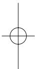
TABLE OF CONTENTS
The Menu System 44
Start-Up Options Menu 45
Normal Operation 46
Simulator 46
System Status 47
Self Test 47
Accessory Test 47
GPS Diagnostic View (937c DF Combo and 937c Combo models only) 47
Sonar X-PressTM Menu 48
Active Side 49
Split Position 49
Sensitivity 49
Upper Range (Advanced: Sonar, Split Sonar and Active Sonar Side Views only) 50
Lower Range 50
Chart Speed 51
Zoom Level (Sonar Zoom View only) 51
Bottom Lock (Sonar Zoom View only) 51
Sonar Colors 51
Navigation X-PressTM Menu (937c DF Combo and 937c Combo models only) 52
Active Side 52
Split Position 52
Save Current Track 53
Clear Current Track 53
Save Current Route (Only when navigating) 53
Skip Next Waypoint (Only when navigating) 53
Cancel Navigation (Only when navigating) 54
Remove Target (Only if a Target is active) 54
Remove Grid (Only if a Grid is active) 54
Sonar Menu Tab 55
Beam Select (937c DF Combo and 931c DF models only) 55
Zoom Width (Sonar Zoom View only) 57
50 kHz Sensitivity (Advanced, 937c DF Combo and 931c DF models only) 58
Depth Lines (Advanced) 58
Surface Clutter (Advanced) 58
Noise Filter (Advanced) 58
Max Depth (Advanced) 59
Water Type (Advanced) 59
Transducer Select 59
Color Bar 60
Temperature (Sonar View only, with Temperature input) 60
Navigation Menu Tab (937c DF Combo and 937c Combo models only) 60
Tracks 61
Waypoints 61
Routes 61
Chart Orientation 62
North Reference 62
Trolling Grid Rotation 62
Trackpoint Interval 62
Track Min Distance (Advanced) 62
Map Datum (Advanced) 63
Export All Nav Data (Advanced) 63
Delete All Nav Data (Advanced) 63
Chart Menu Tab (937c DF Combo and 937c Combo models only) 64
Chart Detail Level 64
Map Borders 64
Lat/Lon Grid 65
Spot Soundings 65
Shaded Depth 65
Set Simulation Position (Advanced) 65
Set Map Offset (Advanced) 66
Clear Map Offset (Advanced) 66
TABLE OF CONTENTS
Alarms Menu Tab 66
Depth Alarm 67
Fish ID Alarm 67
Low Battery Alarm 67
Temp Alarm 67
Off Course Alarm (937c DF Combo and 937c Combo models only) 68
Arrival Alarm (937c DF Combo and 937c Combo models only) 68
Drift Alarm (937c DF Combo and 937c Combo models only) 68
Alarm Tone 69
Setup Menu Tab 70
Units-Depth 70
Units - Temp (International only) 70
Units - Distance (With Speed input only) 71
Units - Speed (With Speed input only) 71
User Mode 71
Language (International only) 71
Triplog Reset (With Speed input only) 72
Restore Defaults 72
Select Readouts (Advanced) 72
Depth Offset (Advanced) 74
Temp Offset (Advanced) 74
Speed Calibration (Advanced, with Speed paddlewheel only) 74
Local Time Zone (Advanced, 937c DF Combo and 937c Combo models only) 74
Daylight Saving Time (Advanced, 937c DF Combo and 937c Combo models only) 75
Position Format (Advanced, 937c DF Combo and 937c Combo models only) 75
Time Format (Advanced, 937c DF Combo and 937c Combo Models, International only) 75
Date Format (Advanced, 937c DF Combo and 937c Combo Models, International only) 75
NMEA Output (Advanced) 76
Sonar (937c DF Combo and 937c Combo models only) 76
Views Menu Tab 77
77
Troubleshooting 78
900 Series™ Doesn't Power Up. 78
900 SeriesTM Defaults to Simulator with a Transducer Attached 78
Display Problems 79
Finding the Cause of Noise 80
1-Year Limited Warranty 81
Humminbird® Service Policy 81
900 Series™ Accessories 82
Specifications 83
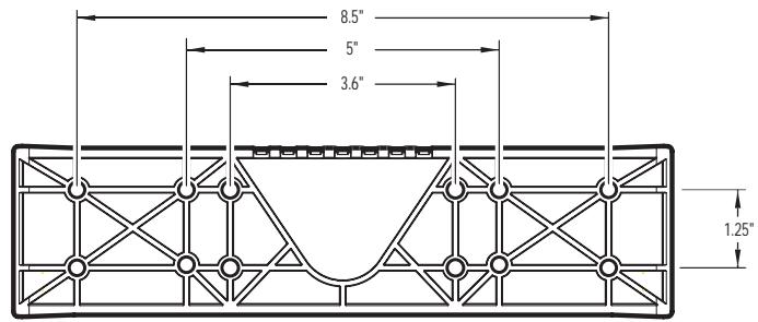
Appendix A - Transducer Mounting Template (Single Frequency: XHS-9-20-T) 84
Appendix B - Transducer Mounting Template (Dual Frequency: XHS-9-DB-74-T) 85
Contact Humminbird 86
NOTE: Entries in this Table of Contents which list (International Only) are only available on products sold outside of the US and Canada by our authorized International Distributors. To obtain a list of authorized International Distributors, please visit our website at www.humminbird.com or contact our Customer Resource Center at 1-800-633-1468 to locate the distributor nearest you.
NOTE: Entries in this Table of Contents which list (with Speed Input) or (with Temperature Input) may require the purchase of separate accessories. You can visit our website at www.humminbird.com to order these accessories online or contact our Customer Resource Center at 1-800-633-1468.
900 SERIES™ INTRODUCTION
Your 900 Series™ Ultra Wide Screen Fishing System comes in several different configurations. See the following list of products, all of which are covered by this manual, to find your 900 Series™ configuration:
NOTE: Only 937c DF Combo and 937c Combo models come with GPS and built-in cartography.
- Humminbird® 931c: Ultra Wide Screen Fishing System with Single Frequency 200 kHz Transducer, optional GPS support
- Humminbird® 931c DF: Ultra Wide Screen Fishing System with Dual Frequency 200 kHz and 50 kHz Transducer, optional GPS support
- Humminbird® 937c Combo: Ultra Wide Screen Fishing System with Chartplotter (Maps) and Single Frequency 200 kHz Transducer, GPS Receiver included
- Humminbird® 937c DF Combo: Ultra Wide Screen Fishing System with Chartplotter (Maps) and Dual Frequency 200 kHz and 50 kHz Transducer, GPS Receiver included.
HOW THE 900 SERIES™ WORKS
Sonar technology is based on sound waves. The 900 Series™ Fishing System uses sonar to locate and define structure, bottom contour and composition, as well as depth directly below the transducer. Your 900 Series™ Fishing System sends a sound wave signal and determines distance by measuring the time between the transmission of the sound wave and when the sound wave is reflected off of an object; it then uses the reflected signal to interpret location, size, and composition of an object. Sonar is very fast. A sound wave can travel from the surface to a depth of 240 ft (70 m) and back again in less than 14 of a second. It is unlikely that your boat can " outrun" this sonar signal.
SINGLE BEAM SONAR
Your 900 Series™ 937c Combo and 931c use a 200 kHz single beam sonar system with a 20^ area of coverage. Depth capability is affected by such factors as boat speed, wave action, bottom hardness, water conditions and transducer installation.
NOTE: The 937c Combo and 931c models use single beam transducers, but may be upgraded to dual beam functionality with the purchase and installation of a dual beam transducer. Contact our Customer Resource Center at either 1-800-633-1468 or visit our website at www.humminbird.com for more information.
NOTE: Your Single frequency (937c Combo or 931c model) 900 Series™ unit was shipped from the factory with a Dual frequency software configuration. Before trying to operate your unit, you will need to set your 900 Series™ to Single Beam in order for it to work properly. See Sonar Menu Tab: Transducer Select for more information.
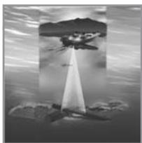
Your 900 Series™ 937c DF Combo and 931c DF are shipped with a 200/50 kHz DualBeam PLUS™ sonar system with a wide (74^) area of coverage. DualBeam PLUS™ sonar returns can be blended together, viewed separately or compared side-by-side. DualBeam PLUS™ is ideal for a wide range of conditions – from shallow to very deep water, in both fresh and salt water. Depth capability is affected by such factors as boat speed, wave action, bottom hardness, water conditions and transducer installation.
GPS AND CARTOGRAPHY
(with 937c DF Combo and 937c Combo models only)
The 937c DF Combo and 937c Combo models use GPS and sonar to determine your position, display it on a grid, and provide detailed underwater information. The Global Positioning System (GPS) is a satellite navigation system designed and maintained by the U.S. Department of Defense. GPS was originally intended for military use; however, civilians may also take advantage of its highly accurate position capabilities, typically within +/- 10 meters, depending on conditions. This means that 95% of the time, the GPS receiver will read a location within 10 meters of your actual position. The GPS Receiver also uses information from WAAS (the Wide Area Augmentation System), EGNOS (the European Geostationary Navigation Overlay Service), and MSAS (the MTSAT Satellite Augmentation System) satellites if they are available in your area.
GPS uses a constellation of satellites that continually send radio signals to the earth. Your present position is determined by receiving signals from up to 12 satellites and measuring the distance from the satellites. The GPS Receiver, when attached to your 937c DF Combo or 937c Combo model, allows you to combine easy-to-use FishingGPS™ chartplotter and navigation capabilities with advanced fishfinding. The following GPS functionality is currently supported by the 937c DF Combo and 937c Combo models when it is connected to a GPS Receiver:
View current position
View current track (breadcrumb trail)
View precision speed and heading from your GPS receiver
- Save tracks, waypoints and routes
- Travel a route and navigate from one waypoint to the next.
NOTE: Only the 937c DF Combo and 937c Combo models support Navionics® Gold Charts marine cartography and Navionics® HotMaps™ 2004 Gold for inland fishing. The 900 Series™ does not support Navionics® Classic Charts.
The 937c DF Combo and 937c Combo models also come with a built-in World map with a more detailed map of North America (Domestic models) or a more detailed map of Europe and Southeast Asia, including Australia and New Zealand (International models).
Your 937c DF Combo and 937c Combo models use the GPS Receiver to determine the position of the boat automatically, and uses the zoom level settings on a particular view to select the best chart to display. See Viewing Cartography for more information.
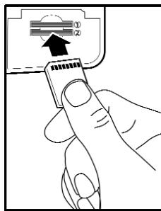
Multi-Media Card (MMC/SD) Slot
MULTI-MEDIA CARD (MMC)/SD SLOT
The 900 Series™ 937c DF Combo and 937c Combo models support cartography, and have two multi-media card (MMC)/SD slots. Optional-purchase MMC and/or SD cards can contain additional detailed maps. You can also export navigation data from your unit onto an MMC/SD card (see Navigation Main Menu: Export All Nav Data). If you insert an MMC or SD card that contains a more detailed chart for a particular location, your unit will retrieve that chart and display it automatically.
931c DF and 931c models have one MMC/SD slot and do not support cartography.
On any model, use the MMC/SD cards to update the software version of your control head. To update the software in your control head, plug in the appropriate MMC/SD card that contains a software update file; the unit will recognize it, will tell you what software version your control head is currently running, and will ask you if you want to update the software in the unit to match that on the MMC/SD card. You can obtain software updates from the www.humminbird.com website.
Use the illustration to locate the position of the MMC and SD slot cover, remove the cover, and then insert an MMC and/or an SD card into one or both slots - either slot can accept either an MMC or an SD card. The label on both types of cards should face down and away from you so that you're looking at the back of the card. Press down on the card until it clicks into place, then replace the slot cover and tighten the screw snugly - do NOT overtighten, as this will not improve water resistance, and may damage the cover.
Accessory Bus
ACCESSORY BUS
Use the Accessory Bus to expand the functionality of your 900 Series™. Accessories plug directly into the 900 Series™, enabling Advanced features such as WeatherSense® and the SmartCast® Wireless Sonar Link. Additional tabs and menu choices will be added to the menu system automatically when an accessory is plugged into the unit. In addition, multiple accessories can be attached simultaneously. See Accessories Menu Tab and 900 Series™ Accessories in this manual, as well as your accessory Operations Manual for additional details.
NOTE: Accessories to enable WeatherSense® and the SmartCast® Wireless Sonar Link require separate purchases. You can visit our website at www.humminbird.com or contact our Customer Resource Center at 1-800-633-1468 for additional details.
INSTALLATION OVERVIEW
Please read all instructions that are relevant for your configuration before beginning the installation process.
NOTE: Installation procedures will depend on product configuration.
The 900 Series™ has a wide variety of configurations.
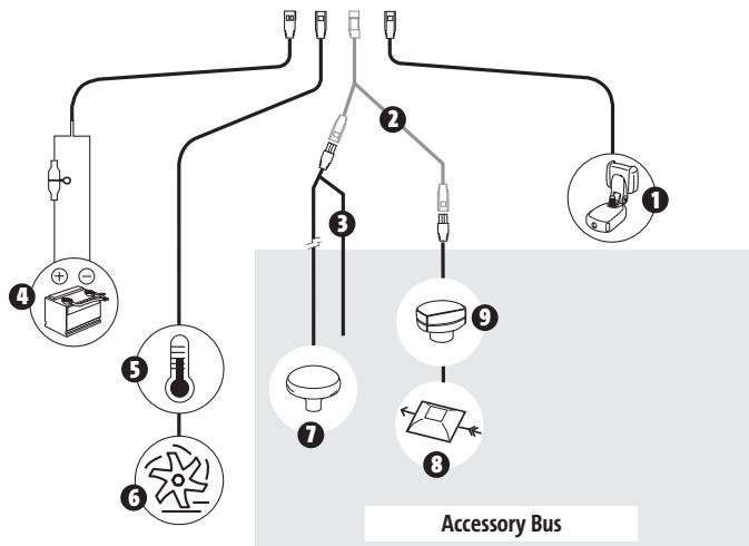
1 Sonar Transducer w/Temperature
Optional "Y" Cable
NMEA0183
Power
3 Temperature
Speed through water 6
GPS Receiver 7
WeatherSense 8
SmartCast® Wireless Sonar Link 9
Inside the boat there is often a channel or conduit used for other wiring, this can be used to route cables. Be sure to route the cable as far as practical from the antenna cable of VHF radios or tachometer cables to reduce the possibility of interference. The transducer and GPS receiver cables should not be cut, and care should be used not to damage the cable insulation.
Basic installation tasks that you must perform include:
- Installing the control head (choosing either gimbal or in-dash mounting)
- Installing the transducer (choosing either the transom mount, inside the hull mount, or trolling motor mounting method)
- Installing the GPS Receiver (if included)
- Installing the Speed accessory (if included)
- Testing the complete installation and locking the transducer position.
The supplied Humminbird® transducer uses a two piece kick-up mounting bracket. In addition, if you purchased a 937c DF Combo or 937c Combo model, you will want to install the included GPS antenna.
NOTE: Accessories may require a separate purchase. You can visit our website at www.humminbird.com to order these accessories online or contact our Customer Resource Center at 1-800-633-1468.
CONTROL HEAD INSTALLATION
You have two choices for mounting your 900 Series™ control head:
- Gimbal mounting, where you use a surface on the boat, such as the dash, to mount the control head so that it can be tilted up or down, or
- In-dash mounting, where you cut a hole in the dash in order to allow the control head to be recessed into the dash, and the control head cannot be moved after mounting.
GIMBAL MOUNTING THE CONTROL HEAD
If you are gimbal mounting the Humminbird® 900 Series™, you can pre-assemble the unit in order to plan the best mounting location.
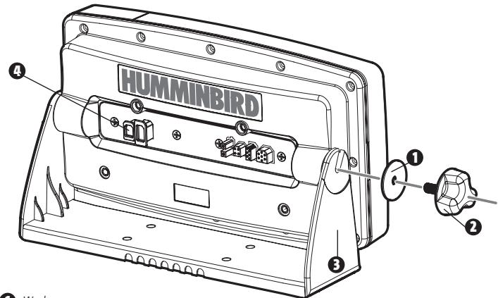
Washer
Gimbal Knob
Gimbal Bracket
Expansion ports - use for future accessories
Parts and tools specific to gimbal mounting are:
Gimbal mounting bracket and screws
Gimbal mounting knobs and washers
Phillips head screwdriver
- 5/16" socket wrench or flat head screw driver
- Hand drill with various drill bits
- Marine-grade silicone sealant.
- Place the control head into the gimbal bracket. Make sure that the straight side of the gimbal arm is against the back side of the control head.
- Place a 1^ (25 mm) diameter black washer on the gimbal knob and then thread the knob and washer into the housing. Tighten the gimbal knob to secure the 900 Series™ control head to the mount. Repeat step 2 for the other side.
You can now place the control head in various locations to decide which is best for mounting. Rotating the mounting bracket to the top of the control head will allow for overhead mounting. The chosen mounting area should allow for sufficient room so the control head can pivot through the full tilt range and allow for easy removal and installation.
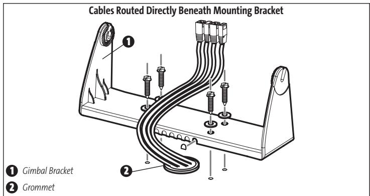
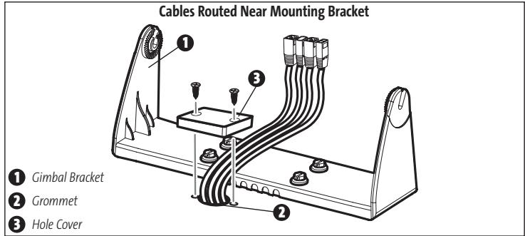
NOTE: You can drill the cable pass hole underneath the gimbal bracket, allowing you to thread the cables through the knock-out holes in the mount; however, if you cannot drill the hole directly under the mounting bracket, then you will need to drill the cable pass hole behind the bracket, and will need to mount the hole cover there instead.
NOTE: When drilling holes in fiberglass hulls, it is best to start with a smaller bit and use progressively larger drill bits to reduce the chance of chipping or flaking the outer coating. Fill all holes with marine grade silicone sealant.
NOTE: You must have underside access to the mounting location to pass the cables through to the surface. Also, make sure that the mounting surface is adequately supported to protect the control head from excessive wave shock and vibration and provide visibility while in operation.
- After the mounting location has been determined, loosen the gimbal knobs and remove the control head from the gimbal bracket.
NOTE: Alternate hole patterns are available underneath the gimbal mounting bracket, and may match existing holes on the boat. If you choose to use one of these alternate hole patterns, simply drill it out and use it to mount the bracket instead.
4. Place the gimbal bracket in the chosen position on the mounting surface and mark the four mounting screw locations using a pencil or center punch.
NOTE: Go to the installation instructions applicable to your transducer, GPS Receiver and accessories. Make the required installations and then run the cables to your control head mounting location. Do not cut any cabling (except the power cable). If your cables are too short, extensions are available from your local dealer or online from www.humminbird.com.
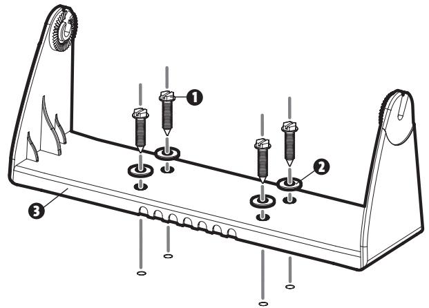
1 Mounting Screws
Washer
Gimbal Mounting Bracket
- Set the gimbal bracket aside and drill the four mounting screw holes using a 5 / 32'' (4.0 mm) drill bit.
6a. If the cables must pass through a hole directly beneath the mounting bracket, mark and drill an additional 1^ (25 mm) hole centered between the four mounting holes. Route the cables through the grommet, then press the grommet in place around the cables and into the 1^ (25 mm) hole. Pass the cables out of the back of the mounting bracket. Using needle-nose pliers, break out the tabs on the rear of the mounting base. You will need to break out the cable tabs for the number of cables you want to run to your control head.
6b. If the cables cannot be routed directly beneath the mounting bracket, mark and drill a 1" (25 mm) hole that will allow you to run the cables close to the bracket. Pass the cables through the 1" (25 mm) hole, routing the cables through the grommet and pressing the grommet into place. Place the hole cover over the mounting surface hole, then use it to mark the position of the two mounting screws. Remove the hole cover, drill the two mounting holes using a 9/64" (3.5 mm) bit, fill them with marine-grade silicone, then replace the hole cover and insert the #8 Phillips countersink wood screws. Hand-tighten only. - Place the mounting bracket on the mounting surface aligned with the drilled holes and fill the mounting holes with marine grade silicone. Insert the four #10 Slotted-Hex wood screws into the mounting holes. Hand-tighten only.
NOTE: Be sure that the cables pass through the slots on the hole cover or gimbal bracket break out tabs and there is enough cable slack to allow for the control head to pivot through its full tilt range. Extra cable slack will also help when connecting/disconnecting the cables.
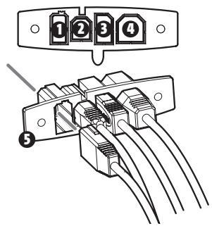
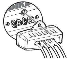
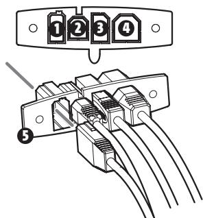
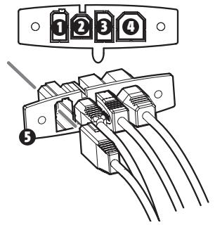
- Insert cable connectors into the proper recesses on the cable collector insert. The cable connectors are keyed to prevent reverse installation, so be careful not to force the connectors into the wrong slots. If you don't have a cable for every hole in the insert, install the blank plugs to protect the control head from the weather.
0 Power
Speed
3 Communications
4 Transducer
Cable Collector Insert
Plug Cable Connector Assembly to Back of Control Head
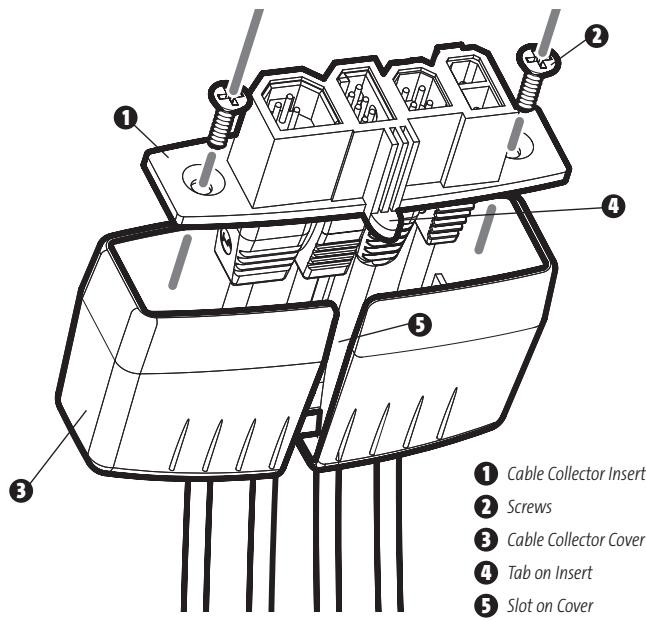
- While holding cables in place in the cable collector insert, thread the cables through the slot in the bottom of the cable collector cover, line up the cable collector insert and cover, then slide the cover into place on the insert.
NOTE: The tab on the Cable Collector insert goes into the slot on the cover.
- Attach the cable collector insert to the cable collector cover using the 2 Phillip screws provided.
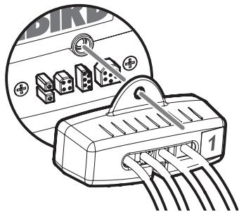
- Place the control head back onto the mounting bracket. Plug in the cable collector assembly to the back of the control head. Cable connectors and cable sockets are keyed to prevent reverse installation, so be careful not to force the connectors into the wrong sockets. Once the cable collector and all cables are plugged into the back of the control head, lock the assembly into place by threading the knurled screw into the threaded insert on the back of the housing. Adjust the control head to the desired viewing angle and secure by tightening the gimbal knobs.
NOTE: You may wish to dress the cabling with nylon wire ties in order to hold the cables together and create a cleaner assembly.
The Humminbird® 900 Series™ control head is now ready for operation.
IN-DASH MOUNTING THE CONTROL HEAD
If you are in-dash mounting the control head, start by placing the components on the surfaces where you intend to install them before installation. Make sure that the surfaces you have chosen provide adequate protection from wave shock, and that all cables can reach the control head.
NOTE: If a cable is too short for your application, extension cables are available. Call Humminbird® Customer Support at 1-800-633-1468 for more information.
Parts and tools specific to In-dash mounting are:
- In-dash mount bracket and threaded rods
- In-dash mounting foam pads
- In-dash mounting template
Reciprocating saw for cutting dash material -
Masking tape to hold mounting template in place.
-
Locate a suitable, flat area of the dash to mount the control head. The control head requires a depth of at least 312 inches.
- Tape the paper In-Dash Mounting template to the desired in-dash mounting location.
- At a location inside the dotted line on the template, drill a hole large enough to insert blade of reciprocating saw. Carefully begin cutting toward the dotted line, then follow the dotted line around the template. Remove the template when finished.
- Insert and tighten the two threaded rods into the two threaded inserts located on the back side of the control head. Peel off the adhesive-backed foam pads and place them on the back of the control head; make sure you notice the difference between the longer top/bottom and shorter side pads.
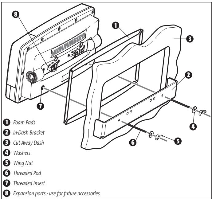
- Insert the control head through the mounting hole from the front side of the dash. From the back side of the dash, align the two threaded rods on the rear of the housing with the two holes on the in-dash mounting bracket. Place a washer onto each threaded rod, then secure bracket by placing a wing nut onto each threaded rod and tighten fully.
-
Insert cable connectors into the proper recesses on the cable collector insert. The cable connectors are keyed to prevent reverse installation, so be careful not to force the connectors into the wrong slots. If you don't have a cable for every hole in the insert, install the blank plugs to protect the unit from the weather.
-
While holding cables in place in the cable collector insert, thread the cables through the slot in the bottom of the cable collector cover, line up the cable collector insert and cover, then slide the cover into place on the insert.
NOTE: The tab on the cable collector insert goes into the slot on the cover.
- Attach the cable collector insert to the cable collector cover using the 2 Phillip screws provided.
- Plug the cable collector assembly into the back of the control head. Cable connectors and cable sockets are keyed to prevent reverse installation, so be careful not to force the connectors into the wrong sockets. Once the cable collector and all cables are plugged into the back of the control head, lock the assembly into place by threading the knurled screw into the threaded insert on the back of the housing. (Cable ties are provided to help you secure the cables in place by threading them through the available holes on the in-dash bracket).
NOTE: It is very important that the cable collector is used and secured in place in the In-Dash installation.
Plug Cable Connector Assembly to Back of Control Head
Power
Temperature
Communications
4 Transducer
Cable Collector Insert

CONNECTING THE CONTROL HEAD POWER CABLE TO THE BOAT
A 6^ (2 m) long power cable is included to supply power to the control head. You may shorten or lengthen the cable using 18 gauge multi-stranded copper wire.
CAUTION: Some boats have 24 or 36 Volt electric systems, but the control head MUST be connected to a 12 VDC power supply.
The control head power cable can be connected to the electrical system of the boat at one of two places: a fuse panel usually located near the console, or directly to the battery.
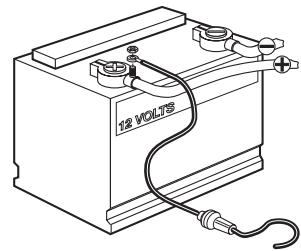
NOTE: Make sure that the power cable is disconnected from the control head at the beginning of this procedure.
1a. If a fuse terminal is available, use crimp-on type electrical connectors (not included) that match the terminal on the fuse panel. Attach the black wire to ground (-) , and the red wire to positive (+) 12 VDC power.
1b. If you need to wire the control head directly to a battery, obtain and install an inline fuse holder and a 2.5 to 3 Amp fuse (not included) for the protection of the unit. Humminbird® is not responsible for over-voltage or over-current failures.
NOTE: In order to minimize the potential for interference with other marine electronics, a separate power source (such as a second battery) may be necessary.
You are now ready to install the transducer. Find the section that refers to your specific transducer installation method.
TRANSDCER INSTALLATION
There are three different installation methods for your transducer:
Transom Transducer
- Inside the Hull Transducer
- Trolling Motor Transducer.
Find the section that describes the method of installation you will be using.
NOTE: If the included transducer will not work for your application, you may exchange it, NEW and UNASSEMBLED, with mounting hardware included, for a transducer appropriate for your application - often at very little or no charge, depending on the transducer. Call the Humminbird® Customer Resource Center (1-800-633-1468) for details and pricing, or visit www.humminbird.com, Product Support/Transducer Exchange for more information.
NOTE: Due to the wide variety of hulls, only general instructions are presented in this installation guide. Each boat hull represents a unique set of requirements that should be evaluated prior to installation. In addition to the parts supplied, you will need a hand drill with various bits, a socket wrench (7/16" or 5/16", depending on transducer type), a Phillips head screwdriver, and marine-grade silicone sealant.
NOTE: When drilling holes in fiberglass hulls, it is best to start with a smaller bit and use progressively larger drill bits to reduce the chance of chipping or flaking the outer coating. Fill all holes with marine grade silicone sealant.
WARNING: Do not touch an active transducer during operation, as this may cause physical discomfort and may result in personal injury in the form of tissue damage. Handle the transducer only when the power to the control head is off.
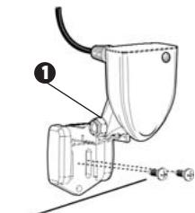
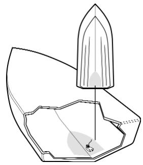
TRANSOM TRANSDUCER INSTALLATION
If you will be installing a transom mounted transducer, use the procedures in this section. You will have one of two different types of transducer, based on whether you have a Single (931c or 937c Combo) or a Dual (931c DF or 937c DF Combo) frequency 900 Series™ control head. There are two pieces to the transducer mount assembly: the pivot, and the bracket. The Single frequency transducer comes with a two-piece plastic bracket assembly, while the Dual frequency transducer comes with a two-piece metal and plastic bracket assembly. Find the correct procedures for your transducer type. There are several procedures you will have to perform in order to install a transom-mounted transducer. They are:
- Determine transducer mounting location
- Mount the bracket to the boat (find the procedure for your transducer, either Single frequency or Dual frequency)
- Attach the pivot to the transducer (find the procedure for your transducer, either Single frequency or Dual frequency)
- Mount the transducer pivot assembly to the bracket (find the procedure for your transducer, either Single frequency or Dual frequency)
- Adjust the running position of the transducer (find the procedure for your transducer, either Single frequency or Dual frequency)
- Route the transducer cable
- Perform a final test of the transom transducer installation.
Rivets/Strakes
Deadrise Angle
Step 3
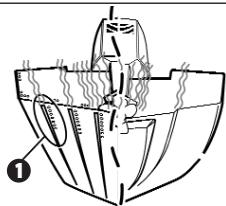
To determine transducer mounting location:
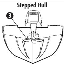
NOTE: If transom mounting is not possible because of a stepped hull or cavitation noise, and you have a single layer fiberglass hull, In-hull installation is an option. See Inside the Hull Transducer Installation for more information.
- First, determine the best location on the transom to install the transducer. Consider the following to find the best location:
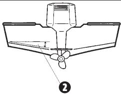
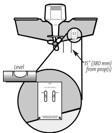
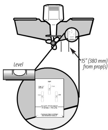
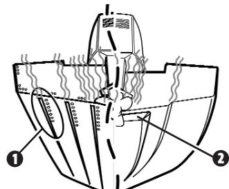
- It is very important to locate the transducer in an area which is relatively free of turbulent water. As a boat moves through the water, turbulence is generated by the weight of the boat, and the thrust of the propeller(s) - either clockwise or counter-clockwise. This turbulent water is normally confined to areas immediately aft of ribs, strakes or rows of rivets on the bottom of the boat, and in the immediate area of the propeller(s). Clockwise propellers create more turbulence on the port side. On outboard or inboard/outboard boats, it is best to locate the transducer at least 15^ (380 mm) to the side of the propeller(s).
- The best way to locate turbulence-free water is to view the transom while the boat is moving. This method is recommended if maximum high-speed operation is a high priority. If this is not possible, select a location on the transom where the hull forward of this location is smooth, flat and free of protrusions or ribs.
- The hydrodynamic shape of your transducer allows it to point straight down without deadrise adjustment.
- On boats with stepped hulls, it may be possible to mount the transducer on the step. Do not mount the transducer on the transom behind a step to avoid popping the transducer out of the water at higher speeds; the transducer must remain in the water for the control head to maintain the sonar signal.
- If the transom is behind the propeller(s), it may be impossible to find an area clear from turbulence, and a different mounting technique or transducer type should be considered (see Inside the Hull Transducer Installation).
To mount the transducer bracket to the boat (Single frequency unit):
- Remove the transducer mounting template from this manual. See Appendix A for the Single Frequency Mounting Template.
NOTE: Please make sure that you use the correct drill holes for the hull composition of your boat.
-
Hold the template on the transom of the boat in the location where the transducer will be installed. Align the template vertically, matching the lower edge of the transom with the bottom corner of the template. If your propeller moves clockwise as the boat moves forward, mount the transducer on the starboard side, and use the bottom left corner of the template. If your propeller moves counterclockwise as the boat moves forward, mount the transducer on the port side, and use the bottom right corner of the template.
-
Using a pencil or punch, mark the two mounting holes (shown on the template for your type of hull) on the transom. Do not mark or drill any other holes at this time.
- Using a 9/64'' (3.5 mm) bit, drill the two holes to a depth of approximately 1'' (25 mm).
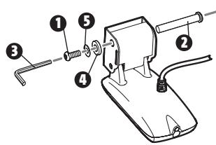
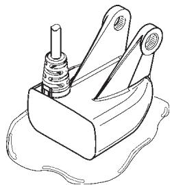
To attach the pivot to the transducer (Single frequency unit):
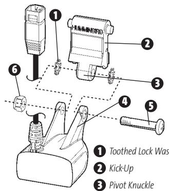
Toothed Lock Washer
Kick-Up
Pivot Knuckle
4 Transducer Arms
Pivot Bolt
6 Nyloc Nut
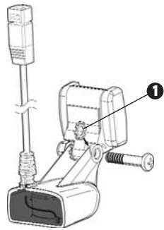
- Attach the Two Piece Kick-Up pivot to the transducer body, using the 1/4'' - 20 × 1 1/4'' Phillips head pivot bolt, the nyloc nut, and the two toothed lock washers.
NOTE: The toothed lock washers must be positioned between the transducer arms and the pivot knuckle regardless of mounting bracket type. - Using a Phillips screwdriver and a 7/16" wrench, loosely tighten the pivot bolt. Do not completely tighten the assembly at this time, so that the pivot angle can be adjusted later.
To mount the transducer pivot assembly to the bracket (Single frequency units):
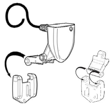
- Insert the pivot/transducer assembly into the mounting bracket.
- Do not snap the assembly closed.
- Apply marine-grade silicone sealant to the mounting holes drilled into the transom.
- Align the transducer assembly with the drilled holes in the transom.
Kick-Up Bracket
- Using the appropriate tool for your mounting hardware, attach the transducer assembly to the boat transom as shown, using # 8 × 5 / 8 (16 mm) wood screws. Do not fully tighten the mounting screws in order to adjust the transducer vertically. Snap the pivot down into place.
NOTE: The running position of the transducer is now completely adjustable. Subsequent adjustment may be necessary to tweak the installation after high speed testing.
To adjust the running position of the transducer (Single frequency unit):
The transducer mounting bracket allows height and tilt adjustment, while the pivot bolt allows angular adjustment. These adjustments will help reduce cavitation. Initially, adjust the transducer as described in the following paragraphs. Further adjustment may be necessary to refine the installation after high-speed testing.
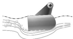
Normal Cavitation
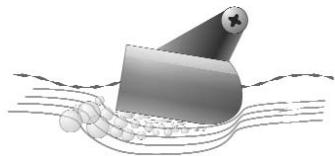
Cavitation that will cause erratic sonar readings
5. Confirm that the pivot angle has not changed.
- First, adjust the pivot angle of the transducer body, so its length is parallel with the length of the hull of the boat. Then, using the angle portion of the mounting template, pivot the transducer down so that it matches the template angle as shown on the template itself.
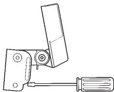
- Fully tighten the pivot bolt, using a Phillips head screwdriver and a wrench. It may be necessary to re-tighten the pivot bolt after initial use as the plastic may still be conforming to the pressure from the lock washers.
- Before removing the template, adjust the height of the assembly so the face of the transducer touches the face of the template. Mark the position of the mounting bracket on the transom with a pencil.
- Force the pivot to the Up position to gain access to the mounting screws. Make sure that the transducer location has not changed, then hand tighten the two mounting screws. Snap the pivot back down.
NOTE: when you are done with this procedure, go to the section entitled: To route the transducer cable.
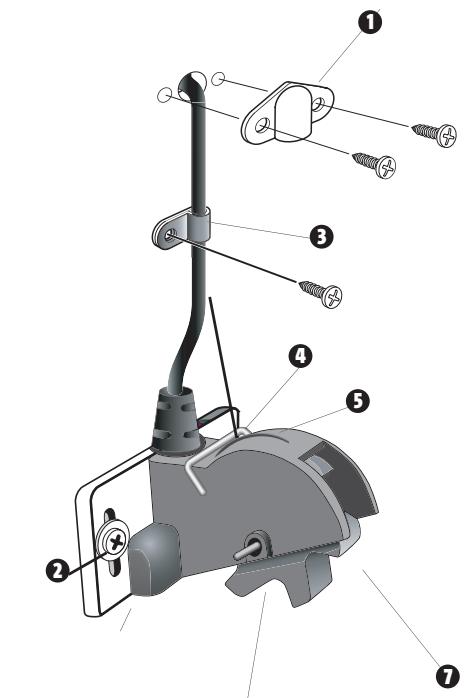
To mount the transducer bracket to the boat (Dual frequency unit):
- Remove the transducer mounting template from this manual. See Appendix B for the Dual Frequency Transducer Mounting Template.
-
Hold the template on the transom of the boat in the location where the transducer will be installed. Align the template vertically, matching the lower edge of the transom with the bottom corner of the template. If your propeller moves clockwise as the boat moves forward, mount the transducer on the starboard side, and use the bottom left corner of the template. If your propeller moves counterclockwise as the boat moves forward, mount the transducer on the port side, and use the bottom right corner of the template.
-
Using a pencil or punch, mark the three mounting holes on the transom. Do not mark or drill any other holes at this time.
- Using a 5/32'' (4.0 mm) bit, drill the three holes to a depth of approximately 1'' (25 mm). On fiberglass hulls, it is best to use progressively larger drill bits to reduce the chance of chipping or flaking the outer coating. Use a marine-grade silicone sealant to fill the drilled holes.
Attaching the Bracket
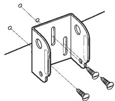
- Align the metal mounting bracket with the mounting holes. The center slot should be above the two outer slots. (This bracket and all other hardware supplied is top quality stainless steel for maximum strength and corrosion protection.) Insert the three 1" (25 mm) flat head wood screws into the drilled holes, but do not completely tighten.
To attach the pivot to the transducer (Dual frequency unit):
- Attach the pivot to the transducer body, using the two 1/4" - 20 × 5/8" (16 mm) machine screws, toothed washers, and square nuts. The toothed washers must fit on the inside of the transducer ears, between the pivot and the ears. The square nuts will be prevented from rotating by the pocket in the back of the pivot. An Allen wrench is provided which fits all the 1/4" - 20 screws, but do not fully tighten the screws at this time.
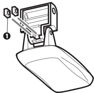
1 Insert the square nuts
Toothed Washer
Pivot
Machine Screw
Attach the Pivot
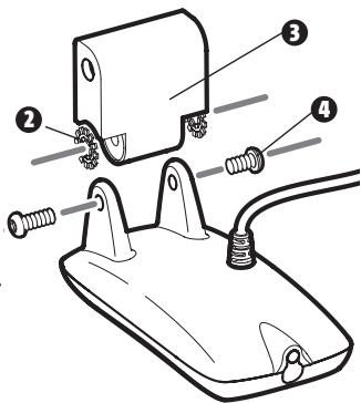
To mount the transducer pivot assembly to the bracket (Dual frequency units):
- Slide the assembled transducer into the metal bracket from the bottom, aligning the large hole at the top of the bracket with the hole in the pivot.
- Insert the headed pin through the pivot holes in the bracket and pivot. The headed pin can be inserted from either side of the bracket.
- Place the nylon washer over the opposite end of the headed pin. Place the stainless washer over the 1 / 4'' - 20 × 5 / 8'' screw threads, then insert into the opposite end of the headed pin and finger tighten only. The screw has a thread locking compound on the threads to prevent loosening, and should not be fully tightened until all adjustments are made.
NOTE: The running position of the transducer is now completely adjustable. Subsequent adjustment may be necessary to tweak the installation after high speed testing.
0 Screw
Headed Pin
3 Allen Wrench
4 Nylon Washer
Stainless Washer
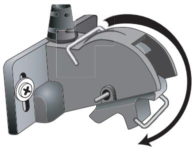
To adjust the running position of the transducer (Dual frequency units):
The transducer mounting bracket allows height and tilt adjustment, while the pivot bolt allows angular adjustment. These adjustments will help reduce cavitation. Initially, adjust the transducer as described in the following paragraphs. Further adjustment may be necessary to refine the installation after high-speed testing.
Cavitation that will cause erratic sonar readings

Normal Cavitation
- First, adjust the pivot angle of the transducer body, so it is parallel with the length of the hull of the boat.
- Fully tighten the two pivot screws, using the supplied Allen wrench. Access to the pivot screws is provided by the lower holes in the side of the mounting bracket. It may be necessary to re-tighten the pivot bolt after initial use as the plastic may still be conforming to the pressure from the lock washers.
Tighten the Mounting Screws
- Adjust the height of the assembly so the face of the transducer is 1/8'' (3 mm) to 1/4'' (6 mm) beneath the bottom of the transom, and fully tighten the three mounting screws.
-
In order to gain access to the mounting screws, the transducer assembly must be pivoted up in the bracket as shown. Be careful not to alter the running angle as some force is necessary to pivot the assembly.
-
If access to the top mounting hole is not possible due to the selected height of the transducer, fully tighten the two lower screws, then simply remove the headed pivot pin and the transducer assembly, and tighten the top screw, then reassemble.
- Confirm that the pivot angle has not changed and that all mounting screws are fully tightened.
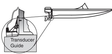
To route the transom transducer cable (all transducers):
The transducer cable has a low profile connector that must be routed to the point where the control head is mounted. There are several ways to route the transducer cable to the area where the control head will be installed. The most common procedure routes the cable through the transom into the boat.
NOTE: Your transducer may not look exactly like the transducer shown in the illustrations, but it will mount in exactly the same way.
NOTE: Your boat may have a pre-existing wiring channel or conduit that you can use for the transducer cable.
- Unplug the other end of the transducer cable from the control head. Make sure that the cable is long enough to accommodate the planned route by running the cable over the transom.
CAUTION! Do not cut or shorten the transducer cable, and try not to damage the cable insulation. Route the cable as far as possible from any VHF radio antenna cables or tachometer cables to reduce the possibility of interference. If the cable is too short, extension cables are available to extend the transducer cable up to a total of 50^ (15 m). For assistance, contact the Customer Resource Center at www.humminbird.com or call 1-800-633-1468 for more information.
NOTE: Since the transducer may need to pivot up to 90^ in the bracket if it strikes an object, make sure there is sufficient cable slack to accommodate this motion. It is best to route the cable to the side of the transducer so the cable will not be damaged by the rotation of the transducer.
- If you will be routing the cable through a hole in the transom, drill a 5/8 diameter (16 mm) hole above the waterline. Route the cable through this hole, then fill the hole with marine-grade silicone sealant and proceed to the next step immediately.
- Place the escutcheon plate over the cable hole and use it as a guide to mark the two escutcheon plate mounting holes. Remove the plate, drill two 9 / 64" (3.5 mm) holes, then fill both holes with marine-grade silicone sealant. Place the escutcheon plate over the cable hole and attach with two # 8 × 5 / 8" (16 mm) wood screws.
- Route and secure the cable by attaching the cable clamp to the transom; drill one 9 / 64'' dia. (3.5mm) × 5 / 8'' deep (16mm) hole, then fill hole with marine-grade silicone sealant, then attach the cable clamp using a # 8 × 5 / 8'' (16mm) screw.
- Plug the other end of the transducer cable back into the control head connection holder.
To perform a final test of the transom transducer installation:
After transom transducer installation, please perform the final testing and then finalize the installation (see Test and Finish the Transducer Installation).
INSIDE THE HULL TRANSDUCER INSTALLATION
If you choose to mount your transducer inside the hull of your boat, perform the procedures in this section. The inside the hull mounting procedure is identical regardless of what type of transducer you have (Single or Dual frequency). In-hull mounting generally produces good results in single thickness fiberglass-hulled boats. Humminbird® cannot guarantee depth performance when transmitting and receiving through the hull of the boat, since some signal loss occurs. The amount of loss depends on hull construction and thickness, as well as the installation position and process.
This installation requires slow-cure two-part epoxy. Do not use silicone or any other soft adhesive to install the transducer, as this material reduces the sensitivity of the unit. Do not use five-minute epoxy, as it has a tendency to cure before all the air bubbles can be purged, thus reducing signal strength.
NOTE: In-hull mounting requires an installed and operational control head.
NOTE: Your transducer may not look exactly like the transducer shown in the illustrations, but it will mount in exactly the same way.
Preferred Mounting Area
Rivets/Strakes
Step
Determine the transducer mounting location:
Decide where to install the transducer on the inside of the hull. Consider the following to find the best location:
- Observe the outside of the boat hull to find the areas that are mostly free from turbulent water. Avoid ribs, strakes and other protrusions, as these create turbulence.
- As a general rule, the faster the boat can travel, the further aft and closer to the centerline of the hull the transducer has to be located in order to remain in contact with the water at high speeds.
Trial installation:
You will not be able to adjust the mounting after an inside the hull transducer is installed. It is best, therefore, to perform a trial installation first that includes running the boat at various speeds, in order to determine the best mounting area before permanently mounting the transducer.
- Plug the transducer into the control head, then power up the control head. When the control head detects a functioning transducer, it will automatically enter Normal operating mode.
- View the sonar signal at its best by holding the transducer over the side, immersed in the water, so that it is pointing straight down over a known flat bottom. Use the display to benchmark against the sonar signal that will be detected once the transducer is placed in the hull.
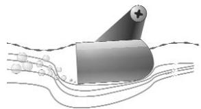
- Place the transducer body face down at the identified mounting location inside the hull, with the end that has the mounting ears pointed towards the bow of the boat.
Transducer Mounted Inside the Hull
-
Fill the hull with enough water to submerge the transducer body. Use a sand-filled bag or other heavy object to hold the transducer in position. The transducer cannot transmit through air, and the water purges any air from between the transducer and the hull, and fills any voids in the coarse fiberglass surface.
-
View the sonar signal on the display and compare against what you observed in Step 2, making sure that the boat is in the same location as it was during your observations in Step 2. If the results are comparable, move on to Step 6. Otherwise, locate a new position in the hull and repeat Steps 3 through 5.
-
Run the boat at various speeds and water depths while observing the screen on the control head. If depth performance is required, test the transducer in water at the desired depth. If the performance is acceptable, move on to Step 7. If the performance is not acceptable, repeat Steps 3 through 6.
- Once you have determined the best mounting location using the above steps, mark the position of the transducer.
Route the cable:
- Once the mounting location is determined and you have marked the position of the transducer, route the cable from the transducer to the control head.
Permanently mount the transducer:
- Make sure the position of the transducer is marked.
- Remove the water from inside the hull and thoroughly dry the mounting surface. If the surface is excessively rough, it may be necessary to sand the area to create a smooth mounting surface.
- Slowly and thoroughly mix an ample quantity of two-part slow cure epoxy. Avoid trapping air bubbles.
- Coat the face of the transducer and the inside of the hull with epoxy.
- Press the transducer into place with a slight twisting motion to purge any trapped air from underneath, keeping the end of the transducer that has the mounting ears pointed forward, towards the bow of the boat.
NOTE: Proper operation requires the end of the transducer that has the mounting ears to face towards the bow of the boat.
6. Weight the transducer so that it will not move while the epoxy is curing.
NOTE: When the epoxy cures, no water is necessary inside the hull.
7. If you unplugged the transducer cable at the beginning of this procedure, plug it back into the control head.
NOTE: Neither water, spilled gasoline, nor oil will affect the performance of the transducer.
TROLLING MOTOR TRANSDUCER INSTALLATION
If you want to install the transducer on a trolling motor, use this procedure. Several styles of the transducer are compatible with trolling motor mounting. If you have a trolling motor bracket, refer to the separate installation instructions that are included with the bracket.
NOTE: After trolling motor transducer installation, please perform the final testing and then finalize the installation (see Test and Finish the Transducer Installation).
If you don't have a trolling motor transducer, there are several options:
- You may purchase a Trolling Motor Adapter kit that will allow you to mount the transducer on the trolling motor.
- You may also exchange your NEW and UNASSEMBLED transducer (with mounting hardware included) for a trolling motor transducer.
There are also several transducer switches available that support the following configurations:
- Two control heads with one transducer
- Two transducers with one control head.
NOTE: Call the Humminbird® Customer Resource Center (1-800-633-1468) for details and pricing, or visit www.humminbird.com for more information.
TEST AND FINISH THE TRANSDUCER INSTALLATION
When you have installed both the control head, the transducer, and accessories and have routed all the cables, you must perform a final test before locking the transducer in place. Testing should be performed with the boat in the water, although you can initially confirm basic operation with the boat out of the water.
NOTE: If you have installed an in-hull mount transducer, this procedure does not apply, as the transducer is already locked in place.
- Press POWER once to turn the control head on. There will be an audible chirp when the button is pressed correctly. If the unit does not power-up, make sure that the connector holder is fully seated and that power is available.
- If all connections are correct and power is available, the control head will enter Normal operation. If no transducer is detected (or one is not connected), the unit will go into Simulator mode and will indicate this by displaying the word Simulator on the control head display.
NOTE: The transducer must be submerged in water for reliable transducer detection.
- If the bottom is visible on-screen with a digital depth readout, the unit is working properly. Make sure that the boat is in water greater than 2 ft (.6 m) but less than the depth capability of the unit, and that the transducer is fully submerged, since the sonar signal cannot pass through air.
- If the unit is working properly, gradually increase the boat speed to test high-speed performance. If the unit functions well at low speeds but begins to skip or miss the bottom at higher speeds, the transducer requires adjustment. Angling the rear of the transducer downward and/or lowering the transducer farther into the water will help achieve depth readings at high speeds. If the left side of the fish arch is longer than the right side, then the back of the transducer is angled too far downward. If the right side of the fish arch is longer than the left side, then the back of the transducer is angled too far upwards.
NOTE: It may not always be possible to get symmetrical fish arches and high speed depth readings at the same time. Due to the wide variety of boat hulls, however, it is not always possible to obtain high speed depth readings.
NOTE: It is often necessary to make several incremental transducer adjustments before optimum high speed performance is achieved.
Once you have reached a consistently good sonar signal at the desired speeds, you are ready to lock down the transducer settings.
5a. If you have a Single frequency transducer, mark the transducer bracket location on the transom with a pencil, then pop up the bracket to reveal the mounting screws. Find the third mounting hole in the vertical center of the bracket. Make sure that the bracket location is the same and follow the drilling instructions for your hull type. Fill the mounting hole with marine-grade silicone, then install the third screw before snapping the transducer bracket closed.
Hand-tighten only!
5b. If you have a Dual frequency transducer, mark the transducer bracket location on the transom with a pencil, then pop up the bracket to reveal the mounting screws. Tighten the stainless steel mounting bracket screws to secure in place.
Hand-tighten only!
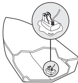
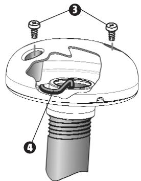
GPS RECEIVER INSTALLATION
(937c DF Combo and 937c Combo models only)
NOTE: You will only need to perform this procedure if you have a GPS Receiver.
To optimize performance of the GPS receiver, mount it in an area that has full exposure to the sky. The effective area of reception is 10^ above the horizon. Different circumstances determine the mounting method appropriate for your GPS receiver.
If you have...
Then use:
An existing antenna stem with standard 1^ - 14 thread stem
Stem Mount with Existing 1"-14 Thread Stem
Access for cable routing under the mounting location
Access Under Mounting Location
No access under the mounting location
No Access Under Mounting Location
STEM MOUNTING WITH AN EXISTING 1" - 14 THREAD STEM
Follow these steps to stem mount the GPS receiver:
NOTE: If you have an existing stem for mounting the GPS receiver, proceed directly to step 2 of the following procedure.
- Determine the best location to mount your GPS receiver. Preplan and test the cable routing to your control head before any drilling or cutting of your boat surfaces. If you have purchased hardware to stem mount your GPS receiver, follow the instructions included with that hardware to mount the stem (antenna pole).
NOTE: ASEC10 10^ extension cables are available from Humminbird® if your planned routing exceeds 20^ (6 m). Maximum cable length, including extensions, should not exceed 50^ (16 m).
NOTE: Remember to caulk or seal screw holes and drilled holes as needed to protect your boat from water damage.
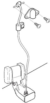
- Screw on the receiver base to the stem first, making sure that the stem pipe does not protrude from the receiver base. This adds protection to the cable when pulling it through the pipe stem. In addition to this, de-burr the pipe edges to reduce cable abrasion.
- Use electrical tape to secure the NMEA pigtail to the cable as shown.
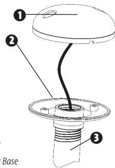
1 Receiver
Receiver Base
Stem Pipe
NOTE: Leave the NMEA pigtail secured to the cable unless needed. This will make removing the receiver easier.
- Route the GPS receiver cable through the stem and continue with the planned route you chose in step 1.
- Attach the GPS receiver to its base using the included #6 - 7/8" screws.
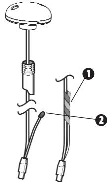
1 NMEA Pigtail Taped
NMEA Pigtail Cable Out
Mounting Screws
4 Cable Route
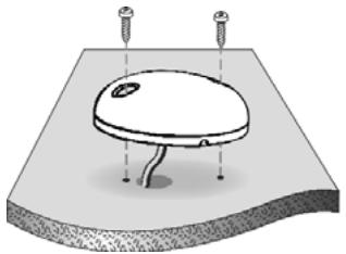
ACCESS UNDER MOUNTING LOCATION
Follow these steps to deck mount the GPS receiver when routing the cable down through the mounting location:
- Determine the best location, then test route the 20^ (6 m) cable from the mounting location to the control head.
NOTE: Installation details may vary with unit configuration. - Mark the mounting location and drill a 3/4'' (19 mm) hole for the cable and cable plug. Route the cable.
- Cover the cable hole with the receiver. Make sure the receiver is flush on the surface and mark the two mounting holes with a pencil or punch.
- Move the receiver to the side and drill two pilot holes using a 9/64'' (3.5 mm) bit.
NOTE: Remember to caulk or seal screw holes and drilled holes as needed to protect your boat from water damage.
5. Align the GPS receiver screw holes over the pilot screw holes and attach with the #8 -1 1/4" Phillips head screws. Hand tighten only!
NOTE: If the mounting surface is thin and made of a lighter material, a backing material may be needed below the mounting surface.
Access Under Mounting Location
No Access Under Mounting Location
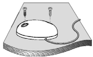
NO ACCESS UNDER MOUNTING LOCATION
Follow these steps to deck mount the GPS receiver in a situation where you must route the cable to the side because there is no space for a cable underneath the mounting location.
- Determine the best location, then test route the cable from the mounting location to the control head.
NOTE: AS-EC10 10' extension cables are available from Humminbird® if your planned routing exceeds 20', (6 m). Maximum cable length, including extensions, should not exceed 50' (16 m). - Confirm the cable length is good and route the cable from the receiver to the control head. If holes are required to route the cable, they must be 3/4'' (19 mm) to allow for the cable connector. Secure the NMEA pigtail with electrical tape.
NOTE: Remember to caulk or seal screw holes and drilled holes as needed to protect your boat from water damage.
- The GPS receiver has two wire routing notches. Use the cable notch closest to the intended cable route.
- With the cable routed, position the GPS receiver in the planned mounting location and mark the mounting holes with a pencil or punch.
- Move the GPS receiver to the side and drill the two 9 / 64'' (3.5 mm) pilot holes.
- Align the GPS receiver's screw holes over the pilot screw holes and attach with the #8-1 1/4" Phillips head screws. Hand tighten only!
After installing a GPS receiver, you should perform the following procedure to finish routing the GPS cable to the control head and to check to make sure that the control head is working correctly.
- Secure the cable along its path to the control head as needed with cable ties.
- Plug the GPS receiver cable into the Communications port on the control head. See Testing the System Installation to use the System Status start-up option and/or the GPS Diagnostic View to confirm a good installation.
Power
Speed
3 Communications
4 Transducer
5 Cable Collector Insert
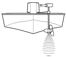
SPEED ACCESSORY INSTALLATION
NOTE: You will only need to perform this procedure if you have a Speed-Only Sensor.
Escutcheon Plate
Wood Screw and Washer
3 Cable Clamp
4 Axial Clip
5 Wedge
6 Paddlewheel
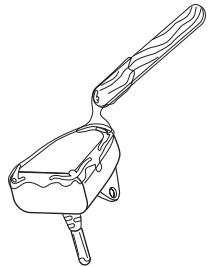
Speed Accessory
The Speed accessory incorporates a paddlewheel-type speed sensor in a high-impact plastic housing. The module is intended for installation on the transom, and will work well on almost any boat.
In addition to the parts supplied, you will need a hand drill with various bits, marine-grade silicone sealant, and a Phillips head screwdriver.
Install the Speed accessory:
- Locate an area on the transom of your boat that will be 6'' to 8'' or farther from the transducer(s). This area must also maintain contact with the water, even at high speeds. Do not mount the accessory directly in front of the propeller or outdrive, and make sure that there are no protrusions such as ribs, rows of rivets, or transducers directly forward of the mounting location, as these may affect the flow of water over the paddlewheel.
- Align the accessory on the transom so that the lower edge is flush with the hull of the boat and the tab on the bottom of the housing aligns with the bottom of the hull, and mark the hole locations. If the transom angle is excessive, a fairing block may be needed to level the paddlewheel for proper operation.
- On fiberglass hulls, it is best to start with a smaller drill bit and use progressively larger bits to reduce the chance of chipping or flaking the outer coating. Drill two 9/64'' (3.5 mm) mounting holes approximately 3/4'' (19 mm) deep.
- Seal the mounting holes with marine-grade silicone sealant, and attach the module to the transom using the two washers and two screws provided.
Hand tighten only!
Routing the speed cable to the control head:
- You may route the cable over the top of the transom, or drill a 5/8 (16 mm) diameter hole in the transom directly above the module and above the waterline to route cable through. Use the cable clamps provided to secure the cable to the transom of the boat. If you use a through-hole, then also use the included escutcheon plate to dress the hole.
NOTE: On fiberglass hulls, it is best to start with a smaller drill bit and use progressively larger drill bits to reduce the chance of chipping or flaking the outer coating.
- All mounting screws require a 5/32'' (13.5 mm) pilot hole drilled approximately 5/8'' (16 mm) deep. Additionally, seal any hole drilled in the transom of the boat with marine-grade silicone sealant (not included).
- Route the cable to the control head, and insert the connector into the appropriate slot. Use the connector designated for accessories on the control head.
- If the connections are correct, the control head will begin displaying boat speed information immediately (assuming that the control head is powered on and the boat is moving). If the speed sensor fails to read properly at high speeds, adjust the height of the module on the transom.
Cleaning the Speed accessory:
- You should periodically remove the paddlewheel from the housing and clean it to remove growth resulting from the marine environment, as a clean paddlewheel results in more accurate readings.
NOTE: This procedure should only be performed when the boat is not running, and is normally performed when the boat is out of the water.
Rotating Retaining Axial Clip to Remove Paddlewheel
- Clean the paddlewheel by disengaging the axial clip from the housing wedge and rotating it forward. Once you have rotated the axial clip, remove it from the housing by sliding it away from the holes in the housing.
- Clean the removed paddlewheel with a mild solution of biodegradable soap or hot water. Clean the wheel well of debris and/or algae at this time.
- Once you have cleaned the paddlewheel, you may re-insert it into the housing. Next, slide the axial clip back into the holes, then rotate it backwards to lock it into place with the wedge in the housing.
NOTE: The paddlewheel must be oriented so that it is scooping the water.
TESTING THE SYSTEM INSTALLATION
After you have completed the installation of the control head, transducer, and any other accessories such as the GPS receiver, and have made all the cabling connections required, you must test the installation before using the system. Thorough testing should be performed with the boat in the water; however, you can confirm basic operation initially with the boat out of the water as well.
To test the installation:
- Press the POWER/LIGHT key on the control head once to turn on the control head. (There will be an audible chirp to let you know that you pressed the key, and the initial Title screen will appear.) If the unit does not power up, make sure that power is available. While the Title screen is shown on the display, press the MENU key to display the Start-Up Options menu. Use the UP or DOWN 4-WAY Cursor keys to position the cursor, then the RIGHT Cursor key to select System Status from the Start-Up Options menu (see the Start-Up Options Menu section for more information about these menu choices). The System Status Self Test screen will appear.
NOTE: If you wait too long, the system will default to whichever menu mode happens to be highlighted, and you will have to start again.
- Self Test displays results from the internal diagnostic self test, including unit serial number, Printed Circuit Board (PCB) serial number, software revision, total hours of operation and the input voltage. See System Status for more information about the Self Test.
- From the System Status screen, view accessory connections by pressing the VIEW key. See System Status for more information about the Accessory Test.
NOTE: The speed accessory (if attached) will be detected only if the paddlewheel has moved since your 900 Series™ was powered up.
- From the System Status screen, see a GPS Diagnostic View by pressing the View key. GPS Diagnostic View shows a sky chart and numerical data from the GPS receiver. The sky chart shows the location of each visible GPS satellite with its satellite number and a signal strength bar. A dark grey bar indicates that the satellite is being used to determine your current position. A light gray bar indicates that the satellite is being monitored, but is not yet being used. See System Status for more information about the GPS Diagnostic View.
NOTE: The GPS Diagnostic View is only available on the 937c Combo and 937c DF Combo models.
GETTING STARTED - USING YOUR 900 SERIES™
Your 900 Series™ Fishing System user interface is easy to use. A combination of keys, different views, and situation-specific, customizable menus allows you to control what you see on the color display. Refer to the following illustration, and see Key Functions, Views, and The Menu System) for more information.
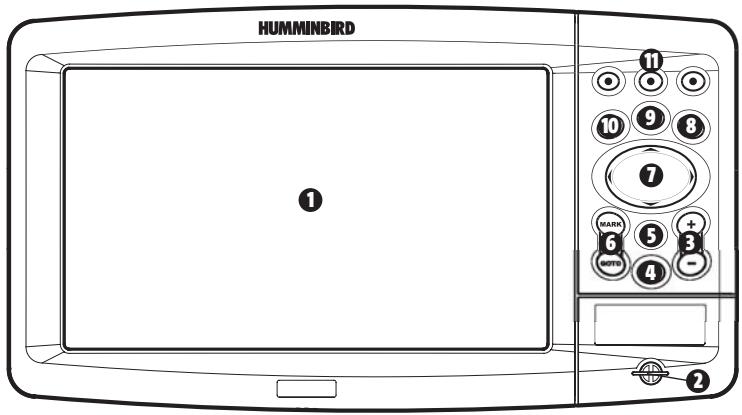
Screen
MMC/SD Card Slot
ZOOM (+ / - ) Key (937c DF Combo and 937c Combo models only)
4 POWER/LIGHT Key
INFO Key (937c DF Combo and 937c Combo models only)
MARK/GOTO Key (937c DF Combo and 937c Combo models only)
4-WAY Cursor Control Key 7
MENuKey 8
VIEWKey 9
EXIT Key 10
VIEW PRESET Keys 1
POWERING UP THE CONTROL HEAD
Turn on your 900 Series™ control head by pressing the POWER key. The Title screen is displayed until the 900 Series™ begins operation. Your 900 Series™ will begin Normal or Simulator operation, depending on the presence or absence of a transducer.
HUMMINBIRD
THE 900 SERIES
937c DF Combo
GPS Fishing System
+Chartplotter
Press MENU for Startup Options
900 Series™ 937c DF Combo Title Screen
WHAT'S ON THE SONAR DISPLAY
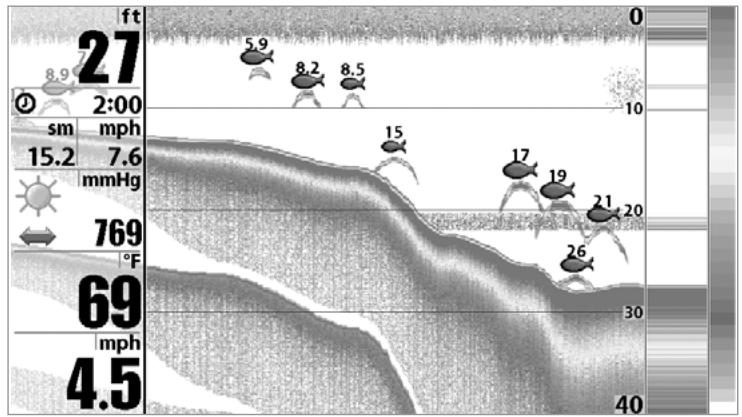
The 900 Series™ can display a variety of useful information about the area under and adjacent to your boat, including the following items:
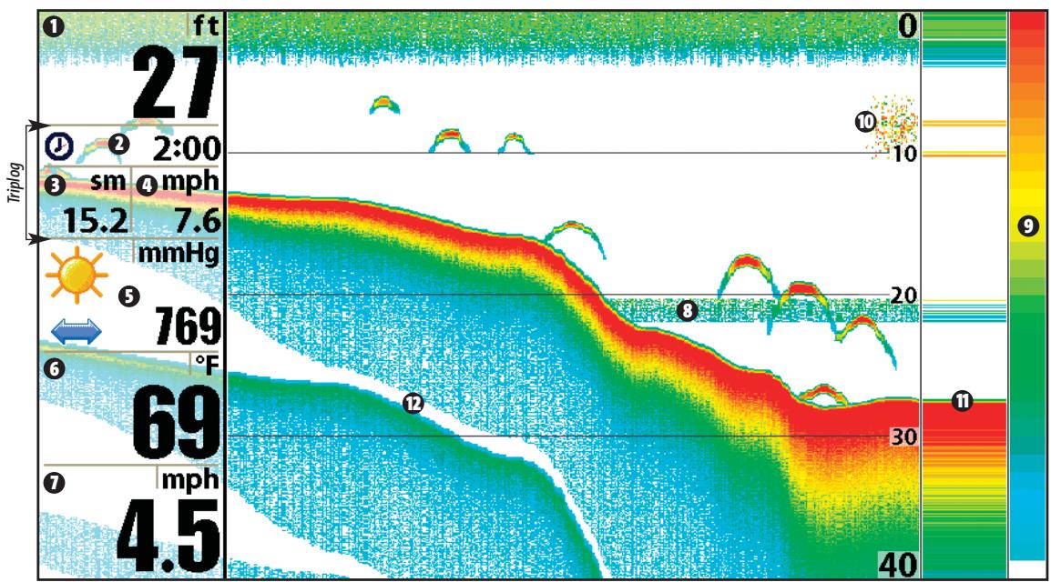
Speed - if a Speed accessory or GPS Receiver is attached, the 900 Series™ can display the speed of the boat, and can keep a triplog of nautical or statute miles traveled.
Thermoclines - layers of water with different temperatures that appear at different depths and different times of the year. A thermocline typically appears as a continuous band of many colors moving across the display at the same depth.
9 Sonar Color Bar - color spectrum indicating low to high sonar intensity returns, where red indicates high intensity and white indicates low intensity.
Bait Ball
RTS® (Real Time Sonar) Window
12 Second Sonar Return - when the sonar signal bounces between the bottom and the surface of the water and back again. Use the appearance of the second return to determine bottom hardness. Hard bottoms will show a strong second return, while soft bottoms will show a very weak one or none at all.
Triplog
Depth - water depth; can be set to alarm when the water becomes too shallow.
Timer - Elapsed time with Speed accessory or GPS Receiver.
Distance - Distance traveled with Speed accessory or GPS Receiver.
Average Speed - Average speed reading with Speed accessory or GPS Receiver.
5 Barometric Pressure - Requires optional-purchase WeatherSense
6 Temperature - water surface temperature
UNDERSTANDING SONAR HISTORY
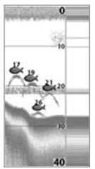
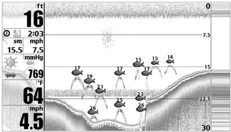
It is important to understand the significance of the 900 Series™ display. The display does NOT show a literal 3-dimensional representation of what is under the water. Each vertical band of data received by the control head and plotted on the display represents something that was detected by a sonar return at a particular time. As both the boat and the targets (fish) may be moving, the returns are only showing a particular segment of time when objects were detected, not exactly where those objects are in relation to other objects shown on the display.
REAL TIME SONAR (RTS®) WINDOW
A Real Time Sonar (RTS®) Window appears on the right side of the display in the Sonar View only. The RTS® Window always updates at the fastest rate possible for depth conditions and shows only the returns from the bottom, structure and fish that are within the transducer beam. The RTS® Window plots the depth and intensity of a sonar return. (See Sonar Menu: RTS® Window).
The Narrow RTS® Window indicates the sonar intensity through the use of colors. Red indicates a strong return and blue indicates a weak return. The depth of the sonar return is indicated by the vertical placement of the return on the display depth scale.
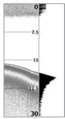
The Wide RTS® Window indicates the sonar intensity through the use of a bar graph. The length of the plotted return provides an indication of whether the return is weak or strong. The depth of the sonar return is indicated by the vertical placement of the return on the display depth scale.
BOTTOM PRESENTATION
As the boat moves, the unit charts the changes in depth on the display to create a profile of the Bottom Contour. The type of bottom can be determined from the return charted on the display. A Hard Bottom such as compacted sediment or flat rock appears as a thinner line across the display. A Soft Bottom such as mud or sand appears as a thicker line across the display. Rocky Bottoms have a broken, random appearance.
NOTE: A sloping bottom will be represented as a thicker line across the display. Harder bottoms typically will be displayed with red and softer bottoms typically will be displayed with blue.
The sonar returns from the bottom, structure and fish can be represented as either Structure ID® or WhiteLine®. See Sonar Menu: Bottom View for details on how to set the bottom view.
Structure ID® represents weak returns in blue and strong returns in red.
WhiteLine® highlights the strongest sonar returns in white, resulting in a distinctive outline. This has the benefit of clearly defining the bottom on the display.
KEY FUNCTIONS
Your 900 Series™ user interface consists of a set of easy-to-use keys that work with various on-screen views and menus to give you flexibility and control over your fishing experience. Regardless of model, your control head will have the following common keys:
- POWER/LIGHT key
- EXIT key
VIEWkey
4-WAY Cursor Control key - MENU key
VIEW PRESET keys.
In addition, if you have a either a 937c DF Combo or a 937c Combo model, your control head will have the following additional, navigation-related keys:
MARK/GOTO key
INFO key
- ZOOM (+/-) key.

POWER/LIGHT KEY
The POWER/LIGHT key is used to turn the 900 Series™ on and off, and also to adjust the backlight and background color of the display. Press the POWER/LIGHT key to turn the unit on. The Title screen is then displayed until the 900 Series™ begins sonar operation.
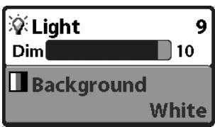
To adjust the backlight or to adjust the display background color, press the POWER/LIGHT key to access the Light and Background menu. Use the 4-WAY Cursor key to select Light or Background and then use the LEFT or RIGHT Cursor key to change the settings. Press EXIT to exit the Light and Background menu.
Press and hold the POWER/LIGHT key for 3 seconds to turn the unit off. A message will appear telling you how many seconds there are until shutdown occurs. Your 900 Series™ should always be turned off using the POWER/LIGHT key. This will ensure that shutdown occurs properly and any menu settings will be saved.

VIEW KEY
VIEW The VIEW key is used to cycle through all available views. Press the VIEW key to advance to the next view. Repeatedly pressing VIEW cycles through all views available. Views can be hidden to optimize the system to your fishing requirements (see View Menu Tab).

MENUKE
The MENU key is used to access the menu system.
Start-Up Options Menu - Press the MENU key during the power up sequence to view the Start-Up Options menu.
X-Press™ Menu - Press the MENU key once for the X-Press™ Menu. The X-Press™ Menu allows you to access frequently-used settings without having to navigate through the whole menu system. When the X-Press™ Menu is displayed, you can use the UP or DOWN Cursor keys to move to a particular menu choice. As soon as you alter a parameter (using the RIGHT or LEFT Cursor keys) the X-Press™ Menu will collapse
temporarily, and the screen will update if it is affected by your menu setting change, allowing you to see the effects of your action immediately. Reactivate the X-Press™ Menu by using the UP or DOWN Cursor keys.
Main Menu - Press the MENU key twice for the tabbed Main Menu System. The Main Menu System is organized under tabbed headings to help you find a specific menu item quickly: Alarms, Sonar, Setup, Views, and Accessories tabs are part of your tabbed Main Menu System. If you have a 937c DF Combo or a 937c Combo model, your menu tabs will also include Navigation and Chart. Use the LEFT or RIGHT 4-WAY Cursor Control key to select a tab; then use the DOWN or UP key to select the menu item, and the LEFT or RIGHT key to alter a menu setting.
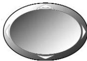
4-WAY CURSOR CONTROL KEY
The 4-WAY Cursor Control Key has multiple functions, depending on the situation:
Freeze Frame - Pressing any arrow on the 4-WAY Cursor Control key will freeze the display in the Sonar View and a cursor and cursor dialog box will be displayed. The cursor can be positioned on the Sonar View using the 4-WAY Cursor Control key.
Active Cursor - In any Bird's Eye View, the 4-WAY Cursor Control key controls the motion of the eyepoint. In any Chart View, the 4-WAY Cursor Control key pans the charts.
NOTE: In either Freeze Frame or Active Cursor mode, you can also make the cursor move diagonally by pressing in between two of the arrows on the 4-WAY Cursor Control key.
Menu Selection - Use the DOWN or UP arrow keys to select a menu choice from the menu list, then use the LEFT or RIGHT arrow keys to change a menu setting.
NOTE: Menu choices are implemented and saved immediately - no further action is required.
VIEW PRESET KEYS
The VIEW PRESET keys are used to program your three favorite views for quick retrieval. Instead of using the VIEW key to cycle through every view to find the one you want, you can program the VIEW PRESET keys to display a specific view immediately. To program each VIEW PRESET key, use the VIEW key to cycle to the view you want to store. Press and hold one of the VIEW PRESET keys for several seconds. A series of audible chirps will be heard indicating that the view has been programmed to the key. You can store up to three views, one on each key.
EXIT
EXIT KEY
The EXIT key has multiple functions, depending on the situation:
If an alarm is sounding, pressing EXIT will cancel the alarm.
- If a menu tab is selected, pressing EXIT will exit the menu mode and return to the view.
- If a menu is active, pressing EXIT will return to the previous level in the menu system.
- Pressing EXIT will cycle through the available views in reverse order.
- If Freeze Frame is active, pressing EXIT will return to a scrolling display.
- If the Cursor is active, pressing EXIT will remove the cursor from the display.

INFO KEY
(937c DF Combo and 937c Combo models only)
Press the INFO key while in any navigation view to display information about objects that are nearest to an active cursor.
Chart Info
Nearest Port
Nearest Tide Station
Nearest Current Station
If the cursor is not active, the following menu will be displayed. Use the 4-WAY Cursor Control key to select Nearest Port, Nearest Tide Station or Nearest Current Station, then use the RIGHT Cursor key to display the requested information.
NOTE: The built-in Uni-Map™ does not contain Port, Tide or Current information. This information is only available from optional purchase MMC/SD cards.

MARK/GOTO KEY
(937c DF Combo and 937c Combo models only)
Press the MARK key while in any view to mark the position of a waypoint, either at the current boat location, or, if the Cursor is active, at the current Cursor location.
If the Cursor is active, pressing the GOTO key while in any view creates a waypoint and starts navigation towards that waypoint. If the Cursor is not active, pressing the GOTO key displays the list of waypoints, so that you can select the waypoint towards which you want to navigate.
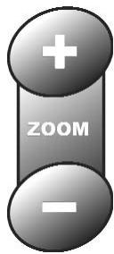
ZOOM (+ / - ) KEY
(937c DF Combo and 937c Combo models only)
Press the - or + ZOOM keys while in any of the Navigation Views or the Sonar Zoom View to change the scale of the view to appear closer or farther away.
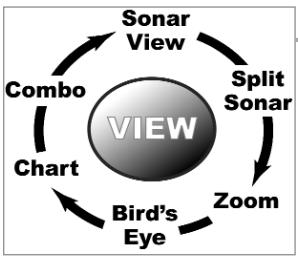
VIEWS
The views available on your 900 Series™ are:
VIEWS AND READOUTS
All views have an Information Bar on the left side of the screen, consisting of readouts that are stacked vertically, and that change from view to view. You can customize the information displayed in individual readouts on many views, including suppressing a particular readout so that nothing is displayed; the ability to customize readouts depends on the view and whether you are navigating (see Setup Menu Tab, Select Readouts for more information).
Sonar views:
- Sonar View
- Sonar Zoom View
- Split Sonar View (937c DF Combo/931c DF models only)
Self Test View - Accessory Test View
Navigation views:
Bird's Eye View (937c Combo/937c DF models only)
Chart/Bird's Eye Combo View (937c DF Combo and 937c Combo models only)
Chart View (937c DF Combo and 937c Combo models only)
Chart/Sonar Combo View (937c DF Combo and 937c Combo models only)
- GPS Diagnostic View (937c DF Combo and 937c Combo models only).
Sonar View is the default view. When the VIEW key is pressed, the display cycles through the available views. When the EXIT key is pressed, the display cycles through the available views in reverse order. Any view can be hidden or displayed as part of the view rotation using the Views Menu tab.
NOTE: When you change any menu settings that affect the sonar, the view will update immediately (i.e. you don't have to exit the menu to apply the change to the screen).
SONAR VIEW
Sonar View presents a historical log of sonar returns. The most recent sonar returns are charted on the right side of the window; as new information is received, the older information is moved across the display to the left. A scale with Upper and Lower Depth Range readouts appears along the right edge of the Sonar View. The scale indicates the distance from the surface of the water to a depth range sufficient to show the bottom. Depth Range is automatically selected to keep the bottom visible on the display, although you can adjust it manually as well (see Sonar X-Press™ Menu).
Sonar View
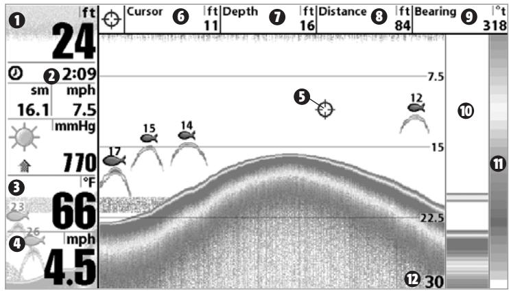
Depth Depth below Cursor
2 Triplog Distance to Cursor 8
Temperature Bearing to Cursor 9
Speed RTS Window 10
Cursor Sonar Color Bar 11
Depth of Cursor Lower Depth Range 17
NOTE: If the Depth number is flashing, it means that the unit is having trouble locating the bottom. This usually happens if the water is too deep, the transducer is out of the water, the boat is moving too fast, or for any other reason that the unit can't accurately receive continuous data.
Freeze Frame - Pressing any arrow on the 4-WAY Cursor Control key will freeze the screen in the Sonar View and a cursor and cursor dialog box will be displayed on the screen. The cursor can be positioned on the display using the 4-WAY Cursor Control key to determine the depth of any sonar return. The RTS® Window continues to update in Freeze Frame. In addition, see the effects of menu setting changes with Instant Image Update.
Pressing EXIT will exit Freeze Frame and the display will start to scroll.
SONAR ZOOM VIEW
Sonar Zoom View increases the displayed resolution to separate sonar returns that are very close together, such as those caused by fish suspended close to the bottom or within structure. In Zoom View, the display is split to show a narrow slice of the full range view on the right and the zoomed view on the left. The full range view on the right also contains the Zoom Preview Box that shows what part of the full range view is shown in zoom view on the left; the Zoom Preview Box tracks the bottom in the full range view.
As the depth changes, the zoomed view updates automatically to display a magnified image of the bottom. The Zoom Preview Box shows where the zoomed view is in relation to the full range view. The Zoom Level, or magnification, is displayed in the lower left corner and can be changed to suit conditions (see Sonar X-Press™ Menu: Zoom Level). Upper and Lower Zoom Depth Range numbers indicate the depth of the water which is being viewed.
Freeze Frame - Pressing any arrow on the 4-WAY Cursor Control key will freeze the screen in the Sonar Zoom View and a cursor and cursor dialog box will be displayed on the screen. The cursor can be positioned on the display using the 4-WAY Cursor Control key to determine the depth of any sonar return. The RTS® Window continues to update in Freeze Frame. In addition, see the effects of menu setting changes with Instant Image Update.
Pressing EXIT will exit Freeze Frame and the display will start to scroll.
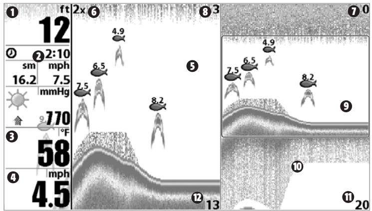
Sonar Zoom View
1 Depth
Triplog
3 Temperature
Speed
Zoomed View
6 Zoom Level
Upper Depth Range, Full Range View 7
Upper Depth Range, Zoom View 8
Zoom Preview Box 9
Full Range View 10
Lower Depth Range, Full Range View 1
Lower Depth Range, Zoom View
SPLIT SONAR VIEW
(937c DF Combo and 931c DF models only)
Split Sonar View displays sonar returns from the 50 kHz wide beam on the left side of the screen and displays sonar returns from the 200 kHz narrow beam on the right side of the screen. You can use the Split Sonar View to make side by side comparisons between the sonar returns from the 50 kHz wide beam and the 200 kHz narrow beam.
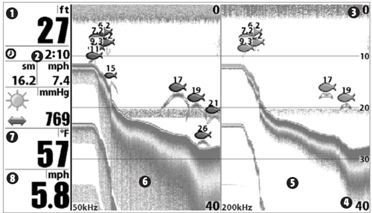
Split Sonar View
1 Depth
2 Triplog
Upper Depth Range
Lower Depth Range
200 kHz Sonar History Window
50 kHz Sonar History Window 6
Temperature 7
Speed 8
BIRD'S EYE VIEW
(937c DF Combo and 937c Combo models only)
Bird's Eye View shows a 3D perspective view of the track and the chart land contour from a point above and behind the boat (the eye point). As the boat turns, the eye point moves to follow the boat. Big Digits on this view provide digital data in a large, easy-to-see format.
When you press the 4-WAY Cursor key in the Bird's Eye View, the position of the eye point will shift. This allows you to move and turn the eye point so that you can look off to the sides, or even behind the boat. Pressing the RIGHT or LEFT arrow keys on the 4-WAY Cursor key turns the eye point right or left, while pressing the UP arrow key moves the eye point forward, and pressing the DOWN arrow key moves the eye point backward.
Pressing the EXIT key moves the eye point back to its original position behind and above the boat.
Bird's Eye View
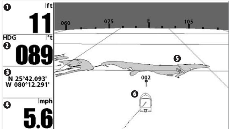
0 Depth
2 HDG:1
North Reference

Latitude and Longitude Position of Boat
Speed of Boat 4
Land Contours 5
Boat Icon 6
CHART/BIRD'S EYE COMBO VIEW
(937c DF Combo and 937c Combo models only)
Chart/Bird's Eye Combo View shows both the Chart and Bird's Eye views in a combination split screen. You can perform any of the functions for either of these views, but only when the view you want to control is selected as the active side (see Sonar X-Press™ Menu: Active Side or Navigation X-Press™ Menu: Active Side for more information). A green arrow points to the side that is active. You can also adjust the size of the left side of a split screen (see Sonar X-Press™ Menu: Split Position or Navigation X-Press™ Menu: Split Position for more information).
NOTE: See Bird's Eye View and Chart View for more information about each side of this view.
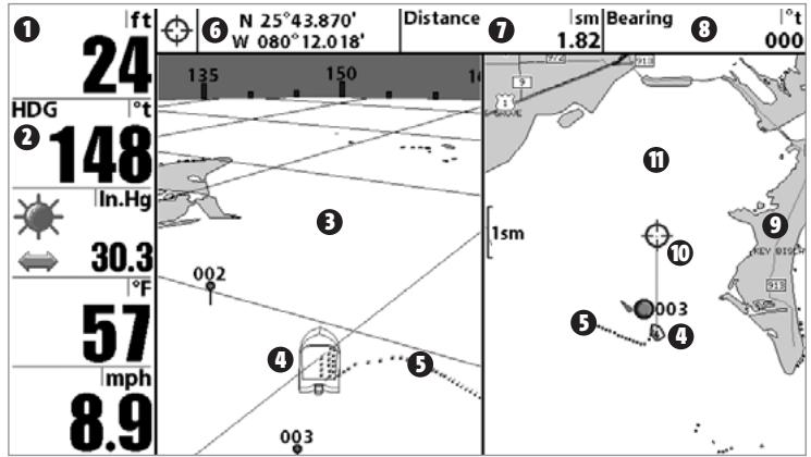
Chart/Bird's Eye Combo View
1 Depth
HDG: Direction that boat is travelling relative to North Reference
3 Bird's Eye Window
4 Boat Icon
Track(Breadcrumb Trail)
Latitude and Longitude Position of Cursor 6
Distance to the Cursor 7
Bearing to the Cursor 3
Cartography 9
Active Cursor 10
Chart Window 1
CHART VIEW
(937c DF Combo and 937c Combo models only)
Chart View shows cartography from the built-in UniMap™ or an optional MMC map for the area surrounding your current position. The current track (also known as the position history or breadcrumb trail) showing where the boat has been, along with saved tracks, waypoints, and the current route (when navigating), are overlaid on the chart. You can use the 4-WAY Cursor Control key to shift/pan the chart to another area. You can use the ZOOM (+/-) keys to zoom in and out. You can use the INFO key to get information on the chart objects near the cursor.
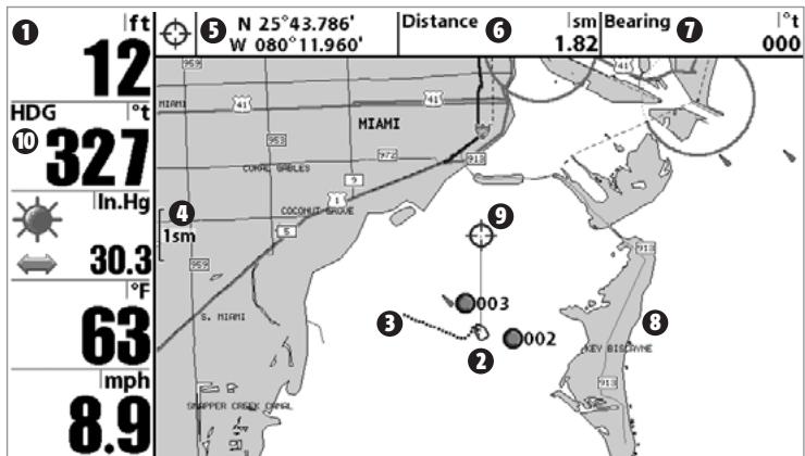
Chart View with Active Cursor
0 Depth
Boat Icon
Track(Breadcrumb Trail)
Map Scale
Latitude and Longitude Position of Cursor
Distance to the Cursor
Bearing to Cursor 7
Cartography 8
Active Cursor 9
HDG: Direction that boat is travelling relative to North Reference.
CHART/SONAR COMBO VIEW
(937c DF Combo and 937c Combo models only)
Chart/Sonar Combo View shows both the Chart and Sonar views in a combination split screen. You can perform any of the functions for either of these views, but only when the view you want to control is selected as the active side (see Sonar X-Press™ Menu: Active Side or Navigation X-Press™ Menu: Active Side for more information). A green arrow points to the side that is active. You can also adjust the size of the left side of a split screen (see Sonar X-Press™ Menu: Split Position or Navigation X-Press™ Menu: Split Position for more information).
Note: See Sonar View and Chart View for more information about each side of this view.
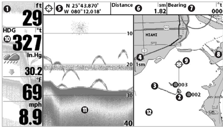
Chart/Sonar Combo View
Depth Bearing to Cursor 7
Boat Icon Cartography 8
3 Track (Breadcrumb Trail) Active Cursor 9
Map Scale HDG: Direction that boat is travelling relative 10
Latitude and Longitude Position of Cursor to North Reference Sonar Window 1
6 Distance to the Cursor Chart Window 12
CHART ORIENTATION
All the chart views allow you to choose the orientation of the chart. When North-Up orientation is selected, True North is shown at the top of the display. In other words, objects located to the north of the boat are drawn above the boat. When Course-Up orientation is selected, the direction of motion of the boat is shown at the top of the display. In other words, objects ahead of the boat are drawn above the boat. In both orientations, the view pans automatically, so that the boat is always centered on the display. When the boat is stationary, it is drawn as a circle. When the boat is in motion, it takes on a boat shape, pointed in the direction of motion (always Up in the Course-Up orientation). See Navigation Menu Tab: Chart Orientation for more information.
VIEWING CARTOGRAPHY
(937c DF Combo and 937c Combo models only)
In the Chart or Combo Views, there are several cartography-related functions that you can access using various keys.
Panning: Use the 4-WAY Cursor keys to move the chart around on the display in the direction of the key being pressed. When you do this, a Bullseye Cursor is drawn at the top of the screen and is linked to the boat by a yellow line, even if the boat is off the screen. At the same time, a cursor dialog box is displayed at the top of the screen with the distance and bearing from the boat to the cursor position and the latitude/longitude coordinates of the cursor. When the cursor is active on the display, you can also use the 4-WAY Cursor Control key to move the cursor diagonally.
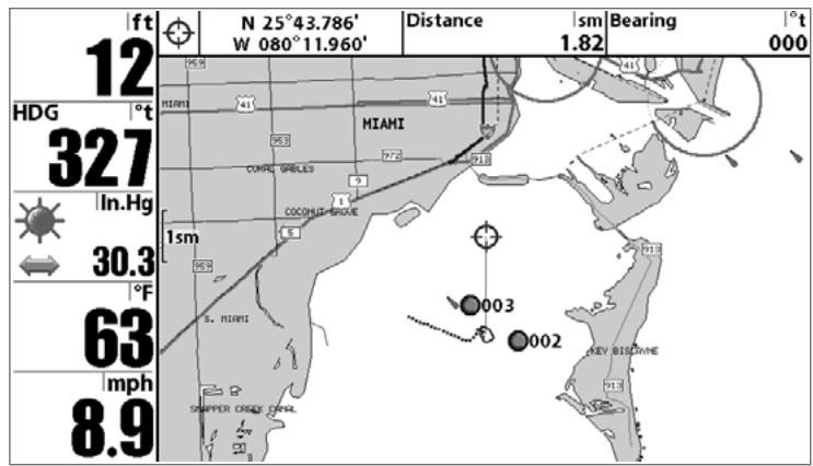
Chart View with Cursor Present
Zooming: Use the Plus (+) key to Zoom In and the Minus (-) key to Zoom Out showing the cartography at different scales. The scale is indicated on the left side of the display. If you zoom in beyond the available chart data, the display will go into Overzoom mode whereby the last available chart data is amplified to reflect the scale selected. If you zoom in so far that no cartography is available, a lat/lon grid will be drawn instead.
Chart Info: Use the INFO key to get detailed information about the chart. If the cursor is active, you will see information about the chart objects located near the cursor. If the cursor is not active, the Chart Info menu will appear. You can select the nearest port, the nearest tide station, or the nearest current station to see information about any of these objects.
NOTE: The built-in UniMap™ does not contain any Port, Tide or Current information. This information is only available from optional purchase MMC/SD cards.
Nearest Port: The position and services information for the nearest port to your present position will be displayed. Press the EXIT key to remove the information box and the Bullseye Cursor will be centered over the port position. The Cursor Information Boxes will indicate the distance and bearing to the port from your present position.
Nearest Tide Station: Tide information for the nearest tide station to your present position will be displayed. This includes the position of the station and the times of the high and low tides for today's date. A tide graph is also displayed showing the rise and fall of the tides for the 24 hour time period encompassing the date. You can change the date to look at tide information before or after the date displayed by pressing the LEFT or RIGHT Cursor key respectively. Press the EXIT key to remove the information box and the Bullseye Cursor will be centered over the tide station position. The cursor information boxes will indicate the distance and bearing to the tide station from your present position.
Nearest Current Station: Current information for the nearest current station to your present position will be displayed. This includes the position of the station and the current changes for today. Two graphs are also presented that show the time, direction and flow speed of the current changes for the 24 hour time period of today's date. You can change the date to look at current information before or after the date displayed by pressing the LEFT or RIGHT Cursor key respectively. Press the EXIT key to remove the information box and the Bullseye Cursor will be centered over the current station position. The Cursor Information Boxes will indicate the distance and bearing to the current station from your present position.
NAVIGATION
(937c DF Combo and 937c Combo models only)
Use the 900 Series™ to establish waypoints at areas of interest and to navigate to those waypoints via a saveable route (representing the shortest intended distance between waypoints). You can also view and save tracks, which represent the actual path of the boat.
WAYPOINTS, ROUTES AND TRACKS
(937c DF Combo and 937c Combo models only)
Waypoints are stored positions that allow you to mark areas of interest or navigation points. Your 900 Series™ can store up to 3000 waypoints.
Waypoints, Routes and Tracks
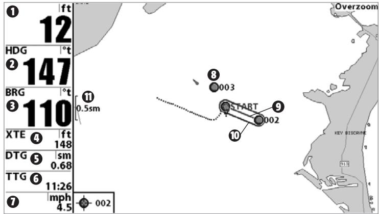
TTG: Estimate of Trip Time to Destination Waypoint 6
1 Depth
HDG: Direction that boat is traveling relative to North Reference
BRG: Direction to Destination Waypoint Relative to North Reference
XTE: Cross Track Error. Distance of Boat from Route
DTG: Distance to Go to Waypoint
Speed of Boat 7
Waypoint 8
Route 9
Off-Course Alarm Limits 10
Map Scale
Routes link two or more waypoints together to create a path for navigation, and are used in trip planning. You can link individual waypoints together by using the GOTO key. A route represents your intended navigation and shows the shortest path from each waypoint to the next. As you travel a route, staying on the route line is the most efficient way to get to your destination, although you should always look out for obstacles not shown on the chart. Your 900 Series™ can store up to 50 routes that can each contain up to 50 waypoints.
Tracks consist of detailed position history, and are displayed as a breadcrumb trail of trackpoints. The Current Track shows the position history since the unit was powered up (maximum of 20,000 trackpoints displayed). You can clear the Current Track or save it at any time. Your 900 Series™ can store up to 50 saved tracks, each containing 20,000 trackpoints. The current track represents your actual path so far.
SAVE, EDIT, OR DELETE A WAYPOINT
(937c DF Combo and 937c Combo models only)
Save your current position as a waypoint: On any view, press the MARK key to save the current position of the boat as a waypoint.
Save the cursor position as a waypoint: On the Chart or Combo view, use the Cursor key to designate the position you want to save as a waypoint. Then press the MARK key to save the marked position as a waypoint.
Save a position from the sonar history: Use the Cursor key to point to a feature in the sonar history (also called the Sonar Saver feature). Press the MARK key to create a waypoint at the location where that sonar reading was taken. The new waypoint will also record the depth at that location.
NOTE: When you save a waypoint by any of these methods, a numerical waypoint name is automatically assigned. You can edit the waypoint information later to give it a different name and select an icon to represent it (see Waypoint submenu on the Navigation Main Menu Tab).
Display the Waypoints Submenu: From any view, press the MENU key twice to display the Main Menu System, then use the RIGHT Cursor key to select the Navigation tab. Select Waypoints and press the RIGHT Cursor key to display the Waypoints submenu.
Program a specific position as a waypoint: To create a waypoint that is NOT your current position, from the Waypoints submenu, select the Create option and press the RIGHT Cursor key. Use the Cursor keys to program a waypoint name, latitude, longitude, and icon before selecting Save.
Edit a waypoint: From the Waypoints submenu, select Edit and press the RIGHT Cursor key to display a list of saved waypoints. Select the waypoint you want to edit and press the RIGHT Cursor key. Use the 4-WAY Cursor Control key to move from field to field, and the UP and DOWN Cursor keys to changes values once you are in a field. In the Waypoint Name, Latitude and Longitude fields, use the UP and DOWN Cursor keys to change the letter or number. All upper and lower case letters are available, as well as digits 0-9 and some punctuation characters. In the Waypoint Icon field, use the UP and DOWN Cursor keys to change the icon used to represent the waypoint on the Combo and Chart Views. You can exit these fields with the LEFT and RIGHT Cursor keys or by pressing the EXIT key. Select Save and press the RIGHT Cursor key to save your changes.
To make it easier to select a waypoint, select Sort By and press the RIGHT or LEFT Cursor keys to select a sort order:
- Name shows the waypoints alphabetically
Time shows the most recently-created waypoint first - Distance shows the closest waypoint first.
Delete a waypoint: From the Waypoints submenu, select Delete and press the RIGHT Cursor key to display a list of waypoints. Select the waypoint you want to delete, then press the RIGHT Cursor key. You will be asked to confirm deletion before the waypoint is actually deleted.
NAVIGATE TO A WAYPOINT OR POSITION
(937c DF Combo and 937c Combo models only)
Navigate to the cursor position: From any Chart or Combo view, use the Cursor key to select a position or waypoint to which you want to navigate. Press the GOTO key. Navigation will begin immediately.
Navigate to a specified waypoint: Press the GOTO key, then choose the waypoint to which you would like to navigate from the waypoint list and press the RIGHT Cursor key to select it.
NOTE: By repeating the previous instructions, you can add more waypoints to create a longer multi-segment route.
Skipping a waypoint: From the Navigation X-Press™ Menu, select Skip Next Waypoint and press the RIGHT Cursor key. If there is not another waypoint to skip to, navigation will be cancelled.
Cancel navigation: From the Navigation X-Press™ Menu, select Cancel Navigation and press the RIGHT Cursor key. Canceling navigation removes the route and any waypoints created using the GOTO key, but does not remove any saved routes from memory. You will be prompted to save the current route when you cancel navigation.
ADD A WAYPOINT TARGET OR TROLLING GRID
(937c DF Combo and 937c Combo models only)
Add or Remove a Waypoint Target: From the Waypoints submenu (accessed from the Navigation main menu), select Target and press the RIGHT Cursor key to display a list of waypoints. Select the waypoint you want to target. A target consisting of concentric circles centered on the selected waypoint will appear on all of the navigation views; the target shows various distance ranges from the targeted waypoint. To remove the target, choose Remove Target from the Navigation X-Press™ Menu.
NOTE: Only one waypoint can have either a target or a grid at one time. If you apply a target or a grid to a new waypoint, the original waypoint will lose its target or grid.
Chart View with Target
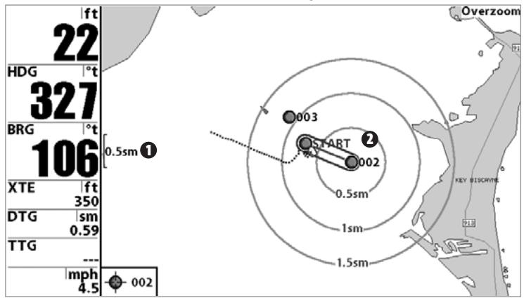
Map Scale
Waypoint Target
Add or Remove a Trolling Grid: From the Waypoints submenu (accessed from the Navigation main menu), select Grid and press the RIGHT Cursor key to display a list of waypoints. Select the waypoint to which you want to add the grid. The trolling grid will appear on all of the navigation views, and can be used as a guide when trolling around a waypoint. The grid can be rotated to any desired heading using Grid Rotation from the Navigation Main menu. To remove the trolling grid, choose Remove Grid from the Navigation X-Press™ Menu.
Chart View with Grid

Map Scale
Waypoint Trolling Grid
NOTE: Only one waypoint can have either a target or a grid at one time. If you apply a target or a grid to a new waypoint, the original waypoint will lose its target or grid.
NOTE: The spacing of the rings on the waypoint target and the spacing of the grid lines on the trolling grid is the same as the length of the scale bar on the left edge of the display. Zooming in or out will decrease or increase the spacing, respectively.
SAVE, EDIT OR DELETE A ROUTE
(937c DF Combo and 937c Combo models only)
Save the current route: While you are navigating, the current route can be saved. From the Navigation X-Press™ Menu, select Save Current Route and press the RIGHT Cursor key. Navigation will continue.
Display the Routes submenu: From any view, press the MENU key twice to display the Main Menu System, then use the RIGHT Cursor key to select the Navigation tab. Select Routes and press the RIGHT Cursor key to display the Routes submenu.
Create a route: From the Routes submenu, select Create and press the RIGHT Cursor key. A Route Edit screen will be displayed with an empty route. You can name the route, add waypoints to the route from the list of all waypoints, and order the waypoints in the route using the Cursor keys.
Edit a saved route: From the Routes submenu, select Edit and press the RIGHT Cursor key. A Route Edit screen will be displayed. Select the route you wish to edit and press the RIGHT Cursor key. Re-name the route or change, delete or re-order the waypoints used in the route.
Delete a saved route: From the Routes submenu, select Delete and press the RIGHT Cursor key. Select the route you wish to delete and press the RIGHT Cursor key. You will be asked to confirm your choice by pressing the RIGHT Cursor key again before the route is deleted.
Travel a saved route: From the Routes submenu, select Travel and press the RIGHT Cursor key. A list of saved routes will appear. Select the route you wish to travel and press the RIGHT Cursor key to make this route the current route and begin navigation. You may also travel the route in either forward or reverse order.
Route Info: From the Routes submenu, select Info and press the RIGHT Cursor key. A list of saved routes will appear. Select the route for which you want information, and press the RIGHT Cursor key. The list of waypoints in the route will be shown, with the distance and bearing from each waypoint to the next, as well as the distance and bearing from the current position to the first waypoint in the route.
SAVE OR CLEAR A CURRENT TRACK
(937c DF Combo and 937c Combo models only)
Save the current track: From the Navigation X-Press™ Menu, select Save Current Track and press the RIGHT Cursor key. The track will remain on the display, but will change from black to gray. To remove the track completely from the display, see Edit, Delete or Hide Saved Tracks.
NOTE: When you save a track, a name is automatically assigned. The track name consists of a date/time stamp, but can be re-named later (see Edit, Delete, or Hide Saved Tracks).
Clear the current track: From the Navigation X-Press™ Menu, select Clear Current Track and press the RIGHT Cursor key. The track will be removed from the display and discarded.
EDIT, DELETE OR HIDE SAVED TRACKS
(937c DF Combo and 937c Combo models only)
Display the Tracks Submenu: From any view, press the MENU key twice to display the Main Menu System, then use the RIGHT Cursor key to select the Navigation tab. Select Tracks and press the RIGHT Cursor key to display the Tracks submenu.
Edit a saved track: From the Tracks submenu, select Edit and press the RIGHT Cursor key to display the list of saved tracks. Select the track you want to edit and press the RIGHT Cursor key. When the Edit Track dialog box appears, use the Cursor keys to move between fields. In the Track Name field, the UP and DOWN Cursor keys change the letter or number. All upper and lower case letters are available, as well as digits 0-9 and some punctuation characters. You can exit the Track Name field with the LEFT and RIGHT Cursor keys or by pressing the EXIT key. Select Save and press the RIGHT Cursor key to save your changes.
Delete a saved track: From the Tracks submenu, select Delete and press the RIGHT Cursor key to display the list of saved tracks. Select the track you want to delete and press the RIGHT Cursor key. You will be asked to confirm deletion before the track is actually deleted.
Hide or display a saved track: From the Tracks submenu, select Visibility and press the RIGHT Cursor key to display the list of saved tracks. Select the track you want to hide or display and use the Cursor keys to select Hidden or Visible. Press the EXIT key to return to the Tracks submenu.
THE MENU SYSTEM
The menu system is divided into easy-to-use menu modules. The main components of the menu system are:
Start-Up Options Menu: Press the MENU key during the power up sequence to view the Start-Up Options menu. See Start-Up Options Menu.
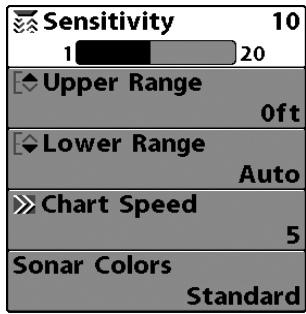
X-PressTM Menu
X-PressTM Menu: The X-PressTM Menu allows you to access the settings that are changed frequently without having to navigate through the whole menu system. Press the MENU key once to display the X-PressTM Menu. When you select a menu item from the X-PressTM Menu, the menu will collapse, leaving only the menu choice on the screen. Use the Up or Down Cursor keys to reactivate the X-PressTM Menu.
NOTE: The X-Press™ Menu choices will vary depending on which view is active when you press the MENU key, as well as whether you are in Normal or Advanced User Mode. Either the Sonar or Navigation X-Press™ Menu will appear, depending on the view you are in.
Main Menu Tabs: Less frequently-adjusted menus are grouped into the Main Menu System. The Main Menu system is organized under main tab menu headings to help you find a specific menu item quickly. If you have a 937c Combo or 937c DF Combo model, main tab headings are: Alarms, Sonar, Navigation, Chart, Setup, Views, and Accessories. If you have a 931c DF or 931c model, main tab headings are: Alarms, Sonar, Setup, Views, and Accessories.
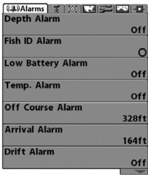
Main Menu System Normal User Mode
Press the MENU key twice for the Main Menu, then use the 4-WAY Cursor LEFT or RIGHT key to select a tab, and use the DOWN or UP key to select a specific menu item under that tab, then use the LEFT or RIGHT keys again to change a menu setting. Press the EXIT key to move quickly to the top of the tab. A down arrow at the bottom of a menu means that you can scroll to additional menu choices using the DOWN Cursor key. A right or left arrow on a menu choice means that you can use the RIGHT or LEFT Cursor keys to make changes or to see more information.
NOTE: The Main Menu choices will vary depending on whether you are in Normal or Advanced User Mode, and what model you own.
User Mode (Normal or Advanced): An Advanced Mode is provided for users who desire the highest level of control over the 900 Series™ and Normal Mode for users who desire greater simplicity and fewer menu choices. Additional Advanced menu choices will be displayed throughout the menu system when you navigate to specific menus while in Advanced Mode. Any changes made while in Advanced Mode will remain in effect after you switch back to Normal Mode. See Setup Menu Tab: User Mode for specific instructions on changing to the User Mode.
NOTE: The 900 Series™ defaults to Advanced User Mode on start-up.
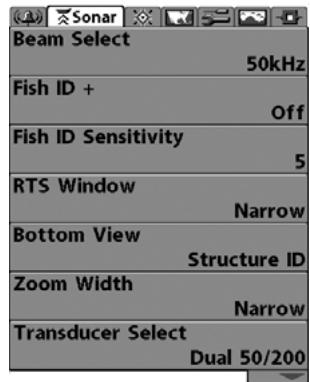
Sonar Tab, Normal Mode
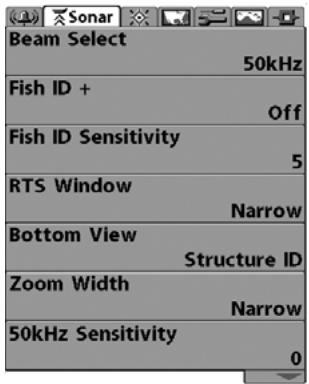
Sonar Tab, Advanced Mode
Total Screen Update: when you change any menu settings that affect the Sonar View, the view will update immediately (i.e. you don't have to exit the menu to apply the change to the screen).
START-UP OPTIONS MENU
Press the MENU key when the Title screen is displayed to access the Start-Up Options menu.
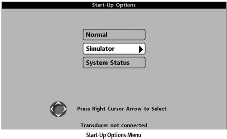
Use the UP or DOWN 4-WAY Cursor keys to position the cursor, then the RIGHT Cursor key to select one of the following choices. If you wait too long, the system will default to whichever menu mode happens to be highlighted:
Normal
- Simulator
- System Status.
See the following paragraphs for more information about each of these choices.
NORMAL OPERATION
Use Normal operation for on-the-water operation with a transducer connected. In addition, your 900 Series™ uses advanced transducer detection methods to determine if a transducer is connected. If a functioning transducer is connected, Normal operation will be selected automatically at power up and your 900 Series™ can be used on the water.
Exit Normal operation by powering your 900 Series™ off.
SIMULATOR
Use the Simulator to learn how to use your 900 Series™ before taking your boat on the water. The Simulator is a very powerful tool that simulates on-the-water operation, providing a randomly-updated display. We recommend going through this manual while using the Simulator, since all of the menus function and affect the display the way they actually do when in Normal operation.
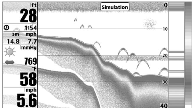
Simulator
NOTE: To get the full benefit of the Simulator, it is important to select Simulator manually from the Start-Up Options menu as opposed to letting the 900 Series™ enter Simulator automatically (as it will if a transducer is not connected and you do nothing during power up). Manually selecting Simulator from the Start-Up Options menu allows you to preconfigure your 900 Series™ for on-the-water operation. Any menu changes you make will be saved for later use.
A Simulation message will appear on the display periodically to remind you that you are using the Simulator.
Exit the Simulator by powering your 900 SeriesTM off.
SYSTEM STATUS
Use System Status to view system connections and to conduct a unit self-test. Exit System Status by powering your 900 Series ^TM off.
The following screens are displayed in turn when you press the VIEW button when using System Status:
Self Test
- Accessory Test
- GPS Diagnostic View (937c DF Combo and 937c Combo models only).
SELF TEST
Self Test displays results from the internal diagnostic self test, including unit serial number, Printed Circuit Board (PCB) serial number, software revision, total hours of operation and the input voltage.
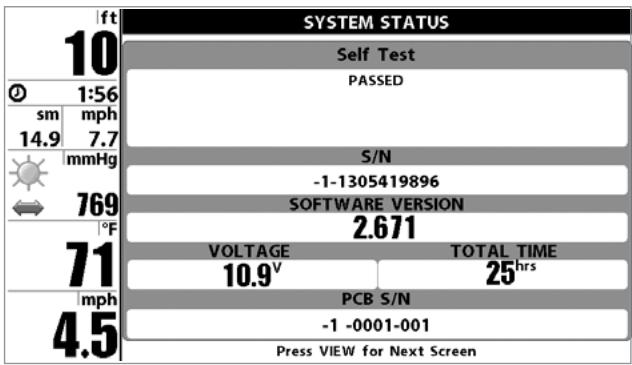
Self Test Screen
ACCESSORY TEST
Accessory Test lists the accessories connected to the system.
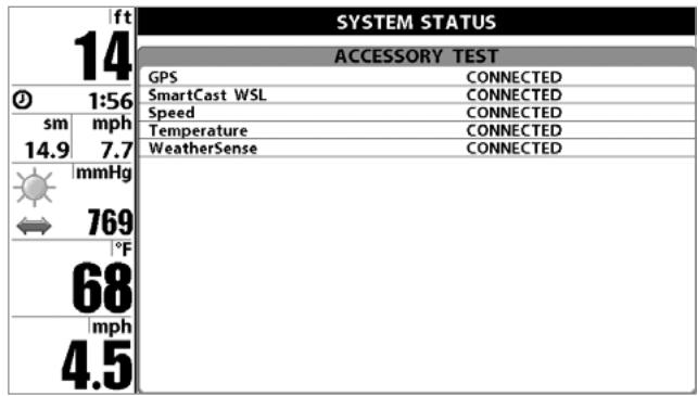
Accessory Test Screen
NOTE: The speed accessory will be detected only if the paddlewheel has moved since your 900 Series™ was powered up.
GPS DIAGNOSTIC VIEW
(With 937c DF Combo and 937c Combo models only)
GPS Diagnostic View, which is only available when a GPS Receiver is attached to you 900 Series, shows a sky chart and numerical data from the GPS receiver. The sky chart shows the location of each visible GPS satellite with its satellite number and a signal strength bar. A dark grey bar indicates that the satellite is being used to determine your current position. A light gray bar indicates that the satellite is being monitored, but is not yet being used.
This view also reports the current position, local time and date, and other numeric information. The current GPS Fix Type is reported as No Fix, 2D Fix, 3D Fix, or Enhanced. An Enhanced fix has been augmented using information from WAAS, EGNOS, or MSAS. A 3D or Enhanced Fix is required for navigation. HDOP (the Horizontal Dilution of Precision) is a GPS system parameter which depends on the current satellite configuration. HDOP is used to calculate the Estimated Position Error.
GPS Diagnostic View
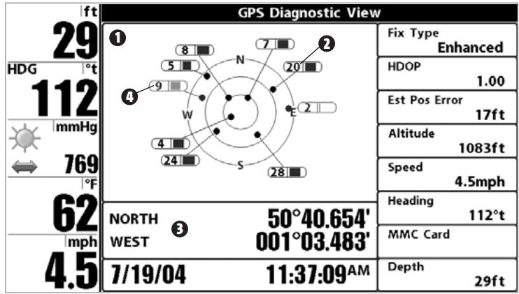
SkyChart
Satellite Being Used
Current Latitude and Longitude
Satellite Being Monitored 4
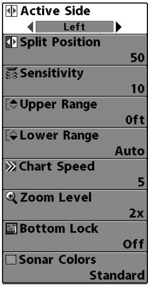
Sonar X-PressTM Menu
SONAR X-PRESS™ MENU
The Sonar X-Press™ Menu provides access to the settings most frequently used. Press the MENU key once while in any of the Sonar Views to access the Sonar X-Press™ Menu.
NOTE: Menu choices will vary depending on system settings such as whether the unit is set for Advanced User mode.
NOTE: The Zoom Level menu option is only available on 931c and 931c DF models.
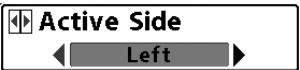
ACTIVE SIDE
Active Side allows you to select which side of a
Combo View will be active; key presses will only affect the active side of the screen. When a menu is displayed, the non-active side of the screen will be grayed out; at any other time, a green arrow will point to the active side. Combo Views usually display sonar on the left, with charts or Bird's Eye usually on the right. The Active Side menu choice is only available when a Combo View is active.
To select the Active Side:
- Highlight Active Side on the Sonar X-Press™ Menu.
- Use the RIGHT 4-WAY Cursor Control key to change which side is active. (Left, Right, Default = Left, or Sonar).
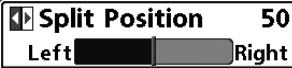
SPLIT POSITION
Split Position allows you to adjust what
percentage of the screen is taken up by the left side of any Combo View; each view may be adjusted independently; you must be in a specific view to adjust the screen size for that view. The number setting indicates the percentage taken up by the left side of the Combo View; selecting Left sets the left side of the screen to its smallest setting. The Split Position menu choice is only available when a Combo View is active.
To Adjust Split Screen Position
- Highlight Split Position on the Sonar X-Press™ Menu.
- Use the RIGHT 4-WAY Cursor Control key to change the size of the left side of a Combo View. (Left,30,40,50,60,70,Right,Default = 50
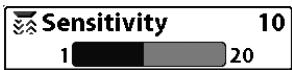
SENSITIVITY
Sensitivity controls how much detail is shown on the
display. Increasing the sensitivity shows more sonar returns from small baitfish and suspended debris in the water; however, the display may become too cluttered. When operating in very clear water or greater depths, increased sensitivity shows weaker returns that may be of interest. Decreasing the sensitivity eliminates the clutter from the display that is sometimes present in murky or muddy water. If Sensitivity is adjusted too low, the display may not show many sonar returns that could be fish.
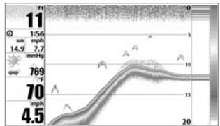
Sensitivity at Low
To adjust the Sensitivity:
- Highlight Sensitivity on the Sonar X-Press™ menu.
- Use the LEFT or RIGHT 4-WAY Cursor Control keys to increase or decrease the Sensitivity setting. (Low = 1, High = 20, Default = 10)
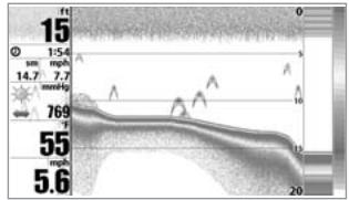
Sensitivity at Medium
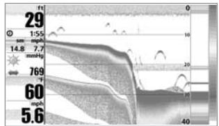
Sensitivity at High
Upper Range 0m 0 927
UPPER RANGE
(Advanced: Sonar, Split Sonar and Active Sonar Side Views only)
Upper Range sets the shallowest depth range that will be displayed on the Sonar, Split Sonar and Active Sonar Side Views. The Upper Range menu choice is available when User Mode is set to Advanced (see Setup Menu Tab: User Mode) and can only be accessed from the Sonar, Split Sonar and Active Sonar Side Views. Upper Range is often used with Lower Range.
For example, if you are only interested in the area between 20 and 50 feet deep, you should set the Upper Depth Range to 20 and the Lower Depth Range to 50. The Sonar View will then show the 30 foot area between 20 and 50, and will not show the surface or the bottom (assuming the bottom is deeper than 50 feet), and will show greater detail for that area between 20 and 50 feet.
NOTE: A minimum distance of 10 feet will be maintained between the Upper and Lower Range regardless of the manual settings entered.
To adjust the Upper Range:
- Make sure you are in Advanced Mode, then highlight Upper Range on the Sonar X-Press™ Menu.
- Use the LEFT or RIGHT 4-WAY Cursor Control keys to increase or decrease the Upper Range setting. (0 to 2490 feet for 937c DF Combo and 931c DF models, 0 to 990 feet for 937c Combo and 931c models, or 0 to 758 meters for 937c DF Combo and 931c DF models or 0 to 301 meters for 937c Combo and 931c models [International models only], Default = 0)
Lower Range Auto Auto 930
LOWER RANGE
will be displayed. Automatic is the default setting. When in automatic mode, the lower range will be adjusted by the unit to follow the bottom. Selecting a specific setting locks the depth range into Manual mode. Use both Upper and Lower Range together to view a specific depth range manually when looking for fish or bottom structure. M will be displayed in the lower right corner of the screen when you start manually adjusting the Lower Range to indicate that you are in Manual mode.
For example, if you are fishing in 60 feet of water but are only interested in the first 30 feet (surface to a depth of 30 feet) you should set the Lower Depth Range limit to 30. The display will show the 0 to 30 foot range, allowing you to see a more detailed view than you would see if the display went all the way to the bottom.
NOTE: A minimum distance of 10 feet will be maintained between the Upper and Lower Range regardless of the settings entered manually.
To adjust the Lower Range:
- Highlight Lower Range on the Sonar X-PressTM Menu.
- Use the LEFT or RIGHT 4-WAY Cursor Control keys to increase or decrease the Lower Range setting. (AUTO, 10 to 2500 feet for 937c DF Combo and 931c DF models, 10 to 1000 feet for 937c Combo and 931c models, 3 to 762 meters for 937c DF Combo and 931c DF models, 3 to 304 meters for 937c Combo and 931c models [International models only], Default = AUTO)
Chart Speed 5 Ultra
CHART SPEED
Chart Speed determines the speed at which the
sonar information moves across the display, and consequently the amount of detail shown. A faster speed shows more information in the Sonar Views and is preferred by most anglers; however, the sonar information moves across the display quickly. A slower speed keeps the information on the display longer, but the bottom and fish details become compressed and may be difficult to interpret. Regardless of the Chart Speed setting, the RTs® Window will update at the maximum rate possible for the depth conditions. Adjust Chart Speed to your personal preference.
To adjust the Chart Speed:
- Highlight Chart Speed on the Sonar X-Press™ Menu.
- Use the LEFT or RIGHT 4-WAY Cursor Control keys to increase or decrease the Chart Speed setting. (1-9, Ultra, where 1 = Slow, 9 = Fast, Ultra = Fastest, Default = 4)
Zoom Level 2x
ZOOM LEVEL
(Sonar Zoom View, 931c DF and 931c models only)
Zoom Level sets the magnification level for the Sonar Zoom View, and is only available on the Sonar X-Press™ Menu when the Sonar Zoom View is active on 931c DF and 931c models. Use Zoom to increase the display resolution to separate sonar returns that are very close together.
To adjust the Zoom Level:
- Highlight Zoom Level on the Sonar X-Press™ Menu.
- Use the LEFT or RIGHT 4-WAY Cursor Control keys to change the Zoom Level setting for the Sonar Zoom View. (2x, 4x, 6x, 8x, Default = 2x)
NOTE: The Zoom Preview Box tracks the bottom and cannot be moved by the user.
Bottom Lock Off
BOTTOM LOCK
(Sonar Zoom View only)
Bottom Lock changes the mode of the Zoomed view in the Sonar Zoom View.
To turn on Bottom Lock:
- In the Sonar Zoom View, highlight Bottom Lock on the Sonar X-Press™ Menu.
- Use the LEFT or RIGHT 4-WAY Cursor Control keys to change the Bottom Lock setting to on. (Off, On, Default = Off).
- Once you turn on Bottom Lock the Bottom Range X-Press menu choice will be displayed. Bottom Range allows you to control the height above the bottom that is shown in the Zoomed view. (10 - 60 feet, 2-10 fathoms, or 3-20 meters [International Models Only])
Sonar Colors Standard
SONAR COLORS
Sonar Colors allows you to select which color
palette you would like to use for the display.
To change the Sonar Colors:
- Highlight Sonar Colors on the Sonar X-Press™ menu.
- Use the LEFT or RIGHT 4-WAY Cursor Control keys to change the color palette. (Standard, Gray, Inverse, Green, Default = Standard)
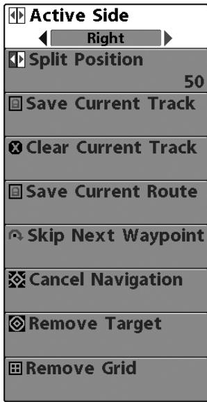
Navigation X-PressTM Menu
NAVIGATION X-PRESS™ MENU
(937c DF Combo and 937c Combo models only)
The Navigation X-Press™ Menu provides access to the settings most frequently used. Press the MENU key once while in the Bird's Eye View, the Chart or the Chart/Sonar Combo or Chart/Bird's Eye Combo View to access the Navigation X-Press™ Menu.
NOTE: Menu choices will vary depending on system settings, such as whether you are currently navigating.
NOTE: You will have to change Active Side setting to Right to see the Navigation X-Press™ Menu from a Combo View with a sonar side.
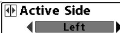
ACTIVE SIDE
Active Side allows you to select which side of a
Combo View will be active; key presses will only affect the active side of the screen. When a menu is displayed, the non-active side of the screen will be grayed out; at any other time, a green arrow will point to the active side. Combo Views usually display sonar on the left, with charts or Bird's Eye usually on the right. The Active Side menu choice is only available when a Combo View is active.
To select the Active Side:
- Highlight Active Side on the Navigation X-Press™ Menu.
- Use the RIGHT 4-WAY Cursor Control key to change which side is active. (Left, Right, Default = Left).
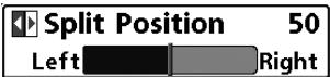
SPLIT POSITION
percentage of the screen is taken up by the left side of any Combo View; each view may be adjusted independently; you must be in a specific view to adjust the screen size for that view. The number setting indicates the percentage taken up by the left side of the Combo View; selecting Left sets the left side of the screen to its smallest setting. The Split Position menu choice is only available when a Combo View is active.
To Adjust Split Screen Position
- Highlight Split Position on the Navigation X-Press™ Menu.
- Use the RIGHT 4-WAY Cursor Control key to change the size of the left side of a split screen. (Left,30,40,50,60,70,Right,Default = 50
Save Current Track
SAVE CURRENT TRACK
Save Current Track allows you to save the current
track being displayed. After the current track is saved, a new current track is started.
To Save Current Track:
- Highlight Save Current Track on the Navigation X-Press™ Menu.
- Use the RIGHT 4-WAY Cursor Control key to initiate saving the current track.
- The Confirm dialog box will appear. To save the current track, press the RIGHT Cursor key once more. To cancel saving the current track, press the LEFT Cursor key.
Clear Current Track
CLEAR CURRENT TRACK
Clear Current Track allows you to clear the current
track being displayed and start a new track at the present position.
To Clear Current Track:
- Highlight Clear Current Track on the Navigation X-Press™ Menu.
- Use the RIGHT 4-WAY Cursor Control key to initiate clearing the current track.
- The Confirm dialog box will appear. To clear the current track, press the RIGHT Cursor key once more. To cancel clearing the current track, press the LEFT Cursor key.
Save Current Route
SAVE CURRENT ROUTE
(Only when navigating)
Save Current Route allows you to save the current route being displayed. This menu choice will only appear when you are currently navigating a route.
To Save Current Route:
- Highlight Save Current Route on the Navigation X-Press™ Menu.
- Use the RIGHT 4-WAY Cursor Control key to initiate saving the current route.
- The Confirm dialog box will appear. To save the current route, press the RIGHT Cursor key once more. To cancel saving the current route, press the LEFT Cursor key.
Skip Next Waypoint
SKIP NEXT WAYPOINT
(Only when navigating)
Skip Next Waypoint removes the next waypoint from the current route. This menu choice will only appear when you are currently navigating a route.
To Skip Next Waypoint:
- Highlight Skip Next Waypoint on the Navigation X-Press™ Menu.
- Use the RIGHT 4-WAY Cursor Control key to initiate skipping the next waypoint.
- The Confirm dialog box will appear. To skip the next waypoint, press the RIGHT Cursor key once more. To cancel skipping the next waypoint, press the LEFT Cursor key.
Cancel Navigation
CANCE NAVIGATION (Only when navigating)
Cancel Navigation discards the current route and exits Navigation Mode. This menu choice will only appear when you are currently navigating a route. This will not delete a previously-saved route.
To Cancel Navigation:
- Highlight Cancel Navigation on the Navigation X-Press™ Menu.
- Use the RIGHT 4-WAY Cursor Control key to initiate canceling navigation.
- The Confirm dialog box will appear. To cancel navigation, press the RIGHT Cursor key once more. To avoid canceling navigation, press the LEFT Cursor key.
Remove Target
REMOVE TARGET (Only if a Target is active)
Remove Target removes the waypoint target from the display. This menu choice will only appear when a target has already been applied to a waypoint.
To Remove a Target:
- Highlight Remove Target on the Navigation X-Press™ Menu.
- Use the RIGHT 4-WAY Cursor Control key to remove the target.
Remove Grid
REMOVE GRID
(Only if a Grid is active)
Remove Grid removes the waypoint grid from the display. This menu choice will only appear when a grid has already been applied to a waypoint.
To Remove a Grid:
- Highlight Remove Grid on the Navigation X-Press™ Menu.
- Use the RIGHT 4-WAY Cursor Control key to remove the grid.
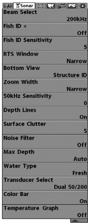
Sonar Menu
SONAR MENU TAB
Press the MENU key twice to access the Main Menu System and then press the RIGHT Cursor key to select the Sonar tab.
NOTE: Menu choices will vary depending on system settings such as whether the unit is set for Advanced User mode or what transducer is currently selected.
Beam Select
200kHz
BEAM SELECT
(937c DF Combo and 931c DF models only)
Beam Select sets which sonar returns from the transducer will be displayed on the screen.
NOTE: This menu choice will only appear if you have a 937c DF Combo or 931c DF model.
When set to 200 / 50kHz , the returns from both beams are blended. The Split Sonar View continues to display the sonar returns from each beam in their respective windows. The blended information is shown in the Sonar View. The RTS® Window in the Sonar View will only show the returns from the 200kHz narrow beam.
When set to 200kHz , only the returns from the 200kHz narrow beam will be displayed in the Sonar View. The Split Sonar View will continue to display returns from both beams in their respective windows. The RTS^® Window in the Sonar View will display the returns from the 200kHz narrow beam.
When set to 50kHz , the returns from the 50kHz wide beam will be displayed in the Sonar View. The Split Sonar View will continue to display returns from both beams in their respective windows. The RTS^® Window will display the returns from the 50kHz wide beam.
To use Beam Select:
- Highlight Beam Select on the Sonar main menu.
- Use the LEFT or RIGHT 4-WAY Cursor Control keys to select either the 200kHz beam, the 50kHz beam or the 200 / 50kHz beam. (200/50 kHz, 200 kHz, 50 kHz, Default = 50 kHz)
Fish ID +
Off
FISH ID+TM
Fish ID^+^TM uses advanced signal processing to
interpret sonar returns, and will display a Fish Symbol when very selective requirements are met. When a fish is detected, a fish icon and its depth are displayed above the return that has been classified as being a fish. Three different fish size icons represent the intensity of the sonar return, and provide an indicator of relative fish size.
DualBeam PLUS^TM sonar models represent targets detected in the 200kHz narrow beam as orange fish symbols, and represent targets detected in the 50kHz wide beam as blue fish symbols.
200 kHz, narrow beam orange fish symbols
50 kHz, wide beam blue fish symbols (937c DF Combo and 931c DF models only)
When Fish ID+™ is turned off, the 900 Series™ shows only the raw sonar returns on the display. These returns will often result in "arches" forming on the display, indicating potential targets. Due to the transducer beam angle, the distance to a fish decreases as the fish moves into the beam, and then increases as it moves out again, creating a Fish Arch when this distance change is shown on the display. Boat speed, chart speed, and the position of the fish within the sonar beam greatly affect the shape of the arch.
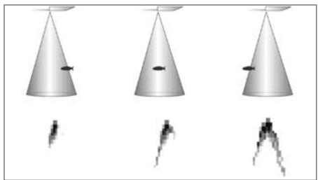
Transducer Cone and Fish Arches
To turn Fish ID + ^TM on or off:
- Highlight Fish ID+ on the Sonar main menu.
- Use the LEFT or RIGHT 4-WAY Cursor Control keys to turn the Fish ID+™ setting On or Off. (Off, On, Default = Off)
Fish ID Sensitivity

FISH ID SENSITIVITY
Fish ID Sensitivity adjusts the threshold of the Fish
ID^+^TM detection algorithms. Selecting a higher setting allows weaker returns to be displayed as fish. This is useful for identifying smaller fish species or baitfish. Selecting a lower setting displays fewer fish from weak sonar returns. This is helpful when seeking larger species of fish. Fish Sensitivity is used in conjunction with Fish ID^+^TM . Fish ID^+^TM must be On for Fish Sensitivity to affect the ability of the 900 Series™ to identify sonar returns as fish.
To change the Fish ID Sensitivity setting:
- Highlight Fish ID Sensitivity on the Sonar main menu.
- Use the LEFT or RIGHT 4-WAY Cursor Control keys to change the Fish Sensitivity setting. (Low = 1, High = 10, Default = 5)
RTS Window
Narrow
REAL TIME SONAR (RTS®) WINDOW
RTS® Window sets the RTS® Window to either
Wide or Narrow, or turns it off in the Sonar View. The RTS® Window always updates at the fastest rate possible and only displays returns that are within the transducer beam. (See Getting Started - Using Your 900 Series™: Real Time Sonar [RTS®] Window for more information.)
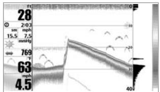
RTS® Window (Wide)
To change the RTS® Window setting:
- Highlight RT5® Window on the Sonar main menu.
- Use the LEFT or RIGHT 4-WAY Cursor Control keys to change the RTS® Window setting. (Wide, Narrow, Off, Default = Narrow)
RTS® Window (Narrow)
RTS® Window (Off)
Bottom View
Structure ID
BOTTOM VIEW
Bottom View selects the method used to the display. Structure ID® represents weak returns hiteLine® highlights the strongest sonar returns in line. This has the benefit of clearly defining the Presentation for more information.
To adjust the Bottom View:
- Highlight Bottom View on the Sonar Main Menu.
- Use the LEFT or RIGHT 4-WAY Cursor Control keys to change the Bottom View setting. (Structure ID, WhiteLine, Default = Structure ID)
Zoom Width
Narrow
ZOOMWIDTH
(Sonar Zoom View only)
Zoom Width allows you to control the width of the Zoomed Sonar (the left-hand side of the screen).
To change the Zoom Width:
- Highlight Zoom Width on the Sonar Main menu.
- Use the LEFT or RIGHT 4-WAY Cursor Control keys to change the width of the Zoomed Sonar. (Narrow, Medium, Wide, Default = Narrow)
50kHz Sensitivity

50 KHZ SENSITIVITY
(Advanced, 937c DF Combo and 931c DF models only)
50 kHz Sensitivity changes the sensitivity of the 50 kHz beam. Increasing the 50 kHz Sensitivity will display additional weak returns and decreasing the 50 kHz Sensitivity will display fewer weak returns. The 50 kHz Sensitivity menu choice is only available when User Mode is set to Advanced (see Setup Menu Tab: User Mode).
To set the 50kHz Sensitivity:
- Make sure you are in Advanced User Mode, then highlight 50 kHz Sensitivity on the Sonar main menu.
- Use the LEFT or RIGHT 4-WAY Cursor Control keys to set the 50kHz Sensitivity. (-10 to +10, Default = 0)
Depth Lines

DEPTH LINES
(Advanced)
Depth Lines divide the display into four equal sections that are separated by three horizontal depth lines. The depth of each line is displayed along the depth scale. You can either turn Depth Lines On or Off. The Depth Lines menu choice is available when User Mode is set to Advanced (see Setup Menu Tab: User Mode).
To change the Depth Lines setting:
- Make sure you are in Advanced User Mode, then highlight Depth Lines on the Sonar main menu.
- Use the LEFT or RIGHT 4-WAY Cursor Control keys to turn the Depth Lines setting On or Off. (Off, On, Default = On)
Surface Clutter

SURFACE CLUTTER
(Advanced)
Surface Clutter adjusts the filter that removes surface clutter noise caused by algae and aeration. The lower the setting, the less surface clutter will be displayed. The Surface Clutter menu choice is available when User Mode is set to Advanced (see Setup Menu Tab: User Mode).
Surface Clutter
To change the Surface Clutter setting:
- Make sure you are in Advanced User Mode, then highlight Surface Clutter on the Sonar main menu.
- Use the LEFT or RIGHT 4-WAY Cursor Control keys to change the Surface Clutter setting. (Low = 1 to High = 10, Default = 5)
Noise Filter

NOISE FILTER
(Advanced)
Noise Filter adjusts the sonar Noise Filter to limit interference on the display from sources such as your boat engine, turbulence, or other sonar devices. The Noise Filter menu choice is available when User Mode is set to Advanced (see Setup Menu Tab: User Mode).
NOTE: The Off setting removes all filtering; Low, Medium and High settings add progressive filtering of the sonar returns. In some deep water situations, the High setting may actually make it harder for the control head to find the bottom.
To change the Noise Filter setting:
- Make sure you are in Advanced User Mode, then highlight Noise Filter on the Sonar main menu.
- Use the LEFT or RIGHT 4-WAY Cursor Control keys to change the Noise Filter setting. (Off, Low, Medium, High, Default = Off)
MAX DEPTH (Advanced)
| Max Depth | Auto |
| Auto | 3000 |
Max Depth adjusts the maximum depth of operation. The performance of your 900 Series™ can be tuned to the maximum depth you will be fishing in by setting the Max Depth. When a maximum depth is set, your 900 Series™ will not attempt to acquire sonar data below that depth, thus increasing overall performance. When Max Depth is set to Auto, the 900 Series™ will acquire bottom readings as needed (within the capacity of the unit). If the bottom is deeper than the Max Depth setting, the digital depth readout will flash, indicating that the 900 Series™ cannot locate the bottom. The Max Depth menu choice is available when User Mode is set to Advanced (see Setup Menu Tab: User Mode).
To change the Max Depth setting:
- Make sure you are in Advanced User Mode, then highlight Max Depth on the Sonar main menu.
- Use the LEFT or RIGHT 4-WAY Cursor Control keys to change the Max Depth setting. (AUTO, 10 to 2500 feet for 937c DF Combo and 931c DF models, 10 to 1000 feet for 937c Combo and 931c models, 3 to 780 meters for 937c DF Combo and 931c DF models, 3 to 330 meters for 937c Combo and 931c models [International models only], Default = AUTO)
Water Type
Fresh
WATER TYPE
(Advanced)
Water Type configures your unit for operation in fresh or salt water. The Water Type menu choice is available when User Mode is set to Advanced (see Setup Menu Tab: User Mode).
NOTE: In salt water, what would be considered a large fish might be 2 to 10 times bigger than a large fish in fresh water (depending on the type of fish you are seeking). The salt water setting allows for a greater range in fish size adjustment to account for this. Also, make sure that the Water Type is set accurately, especially in salt water, as this affects the accuracy of deep water depth readings.
To change the Water Type setting:
- Make sure you are in Advanced User Mode, then highlight Water Type on the Sonar main menu.
- Use the LEFT or RIGHT 4-WAY Cursor Control keys to change the Water Type setting. (Fresh, Salt, Default = Fresh)
Transducer Select
Dual 50/200
TRANSDUCER SELECT
Transducer Select allows you to select which
transducer you want to use, Single Beam or Dual 50/200 Beam.
NOTE: The transducer setting must correspond to the transducer type connected to your system. If you have a Single frequency (937c Combo or 931c model) control head, you will need to set Transducer Select to Single Beam in order for your control head to work properly.
To change the selected Transducer:
- Highlight Transducer Select on the Sonar Main menu.
- Use the LEFT or RIGHT 4-WAY Cursor Control keys to change the transducer selected. (Dual 50/200, Single Beam, Default = Dual 50/200)

COLOR BAR
Color Bar allows you to display or suppress the
display of the color bar shown in the full screen Sonar View.
To change the display of the Color Bar:
- Highlight Color Bar on the Sonar Main menu.
- Use the LEFT or RIGHT 4-WAY Cursor Control keys to change the display of the color bar. (Off, On, Default = On)

TEMPERATURE GRAPH
(Sonar View only, with Temperature input)
Temperature Graph allows you to display or suppress a water temperature graph over the main Sonar View to show temperature changes correlated to recent sonar history.
To change the display of the Temperature Graph:
- In the Sonar View, highlight Temperature Graph on the Sonar main menu.
- Use the LEFT or RIGHT 4-WAY Cursor Control keys to change the display of water temperature. (Off, On, Default = Off)
Navigation Menu
NAVIGATION MENU TAB
(With 937c DF Combo and 937c Combo models only)
Press the MENU key twice to access the Main Menu System, then press the RIGHT cursor key to select the Navigation tab.
NOTE: Menu choices will vary depending on system settings.
TRACKS
Tracks allows you to view the Tracks submenu.
Tracks Submenu
To view the Tracks Submenu:
-
Highlight Tracks on the Navigation main menu.
-
Use the RIGHT 4-WAY Cursor Control keys to view the Tracks submenu.
The Tracks Submenu contains the following menu choices:
Edit allows you to select a previously-saved track and edit its name.
Delete allows you to delete a track from a list of previously-saved tracks.
Visibility allows you to display or hide each saved track.
Waypoints
WAYPOINTS
Waypoints allows you to view the Waypoints submenu.
Waypoints Submenu
To view the Waypoints Submenu:
-
Highlight Waypoints on the Navigation main menu.
-
Use the RIGHT 4-WAY Cursor Control keys to view the Waypoints submenu.
The Waypoints Submenu contains the following menu choices:
Create allows you to create a new waypoint and edit it immediately. The current boat position will be used as the default, but you can set the coordinates to any valid position. The Icon used to represent the waypoint in the Chart and Combo Views can also be changed.
Edit allows you to choose from a list of previously-saved waypoints, then edit the Name, Position (Latitude and Longitude) and select the Icon that will be used to represent the waypoint in the Chart and Combo Views.
Delete allows you to delete a waypoint from the list of saved waypoints.
Go To allows you to select a waypoint and start navigation toward that waypoint, or add that waypoint to the end of the current route.
Target allows you to apply a target to a waypoint selected from the list of waypoints.
Grid allows you to apply a trolling grid to a waypoint selected from the list of waypoints.
Routes
ROUTES
Routes allows you to view the Routes menu.
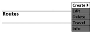
Routes Submenu
To view the Routes Submenu:
-
Highlight Routes on the Navigation main menu.
-
Use the RIGHT 4-WAY Cursor Control keys to view the Routes submenu.
The Routes Submenu contains the following menu choices:
Create allows you to create a new, empty route and add waypoints to it immediately.
Edit allows you to select a previously-saved route and edit its name and the waypoints on it.
Delete allows you to delete a route from a list of previously-saved routes.
Travel allows you to select a previously-saved route to use as the current route; this menu setting also begins navigation on this route. Routes can be traveled in either the forward or reverse direction.
Info displays information about the route, including the distance and bearing from each waypoint to the next.
Chart Orientation North-Up
CHART ORIENTATION
Chart Orientation allows you to select whether
the views containing charts should be drawn North-Up or Course-Up.
To change the Chart Orientation setting:
- Highlight Chart Orientation on the Navigation main menu.
- Use the LEFT or RIGHT 4-WAY Cursor Control keys to change the Chart Orientation setting. (North-Up, Course-Up, Default = North-Up)
NOTE: The Chart Orientation setting does not apply to the Bird's Eye View.
North Reference
True
NORTH REFERENCE
North Reference allows you to have bearings
displayed with one of two orientations: True North or Magnetic North.
To change the North Reference setting:
- Highlight North Reference on the Navigation main menu.
- Use the LEFT or RIGHT 4-WAY Cursor Control keys to change the North Reference setting. (True, Magnetic, Default = True)
Trolling Grid Rotation 0° 089
Trolling Grid Rotation allows you to set the
orientation of the trolling grid in degrees, where a setting of 0^ displays a standard North, South, East, West alignment. See Waypoints for information on how to set a Grid.
To change the Trolling Grid Rotation setting:
- Highlight Trolling Grid Rotation on the Navigation main menu.
- Use the LEFT or RIGHT 4-WAY Cursor Control keys to change the Trolling Grid Rotation setting. (0^ to 89^ , Default = 0^ )
Trackpoint Interval
15 seconds
TRACKPOINT INTERVAL
Trackpoint Interval allows you to select the time
period between trackpoints. The current track can only contain up to 2000 trackpoints, so longer time periods cause the track to extend back further in time, but will be less detailed.
NOTE: Trackpoint Interval works in conjunction with Track Min Distance. Both conditions must be met before a trackpoint is added to the current track.
To change the Trackpoint Interval setting:
- Highlight Trackpoint Interval on the Navigation main menu.
- Use the LEFT or RIGHT 4-WAY Cursor Control keys to change the Trackpoint Interval setting. (1 second, 5 seconds, 10 seconds, 15 seconds, 30 seconds or 60 seconds, Default = 15 seconds)
NOTE: During slow travel or drift, setting both Trackpoint Interval and Track Min Distance to small values will allow you to increase the track resolution.
Track Min Distance


TRACK MIN DISTANCE
(Advanced)
Track Min Distance allows you to set a minimum distance of travel before a trackpoint is added to the track.
NOTE: Track Min Distance works in conjunction with Trackpoint Interval. Both conditions must be met before a trackpoint is added to the current track.
To change the Track Minimum Distance setting:
- Make sure you are in Advanced User Mode, then highlight Track Min Distance on the Navigation main menu.
- Use the LEFT or RIGHT 4-WAY Cursor Control keys to change the Track Min Distance setting. (1 to 300 feet or 1 to 100 meters [International Units Only], Default = 16 ft, 5 m)
NOTE: During slow travel or drift, setting both Trackpoint Interval and Track Min Distance to small values will allow you to increase the track resolution.
Map Datum
WGS 84 (Default)
MAP DATUM
(Advanced)
Map Datum allows you to change the map coordinate system used by the 900 Series™ to match those of a paper map.
To change the Map Datum setting:
- Make sure you are in Advanced User Mode, then highlight Map Datum on the Navigation main menu.
- Use the LEFT or RIGHT 4-WAY Cursor Control keys to change the Map Datum setting. (Default = WGS 84)
Export All Nav Data
EXPORT ALL NAV DATA
(Advanced)
Export All Nav Data allows you to export all saved Tracks, Waypoints and Routes to an MMC/SD card.
To Export All Navigation Data:
- Make sure you are in Advanced User Mode, and that an optional-purchase MMC/SD card is installed in the slot, then highlight Export All Nav Data on the Navigation main menu.
- Use the RIGHT 4-WAY Cursor Control key to export all navigation data.
Delete All Nav Data
DELETE ALL NAV DATA
(Advanced)
Delete All Nav Data allows you to delete all saved Tracks, Waypoints and Routes. This menu choice should be used with caution.
To Delete All Navigation Data:
- Make sure you are in Advanced User Mode, then highlight Delete All Nav Data on the Navigation main menu.
- Use the RIGHT 4-WAY Cursor Control key to delete all navigation data.
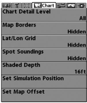
Chart Menu
CHART MENU TAB
(With 937c DF Combo and 937c Combo models only)
Press the MENU key twice to access the Main Menu System and then press the RIGHT Cursor key to select the Chart tab.
NOTE: Menu choices will vary depending on system settings such as whether the unit is set for Advanced User mode.
NOTE: This menu tab only appears on 937c DF Combo and 937c Combo models.
Chart Detail Level
All
CHART DETAIL LEVEL
Chart Detail Level allows you to select how much
chart detail you want displayed on the Navigation Views. Basic shows land areas, ports, obstructions and restricted areas. Navigation shows navaids, landmarks, ferryways and navigation routes in addition to the Basic information. Underwater shows depth contours, fishing areas, underwater wrecks, tides and currents in addition to the Basic and Navigation information. All shows roads, buildings, railways, and other notations in addition to the Basic, Navigation and Underwater information.
To change the Chart Detail Level setting:
- Highlight Chart Detail Level on the Navigation main menu.
- Use the LEFT or RIGHT 4-WAY Cursor Control keys to change the Chart Detail Level setting. (Basic, Navigation, Underwater, All, Default = All)
NOTE: Some chart details are only available with optional-purchase MMC/SD cards.
Map Borders
Hidden
MAP BORDERS
Map Borders allows you to display or hide map
borders. A Map Border indicates an area which contains a different map.
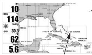
Map Borders
To change the Map Borders setting:
- Highlight Map Borders on the Navigation main menu.
- Use the LEFT or RIGHT 4-WAY Cursor Control keys to change the Map Borders setting. (Hidden, Visible, Default = Hidden)
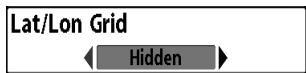
LAT/LON GRID
Lat/Lon Grid allows you to display or hide a grid
To change the Lat/Lon Grid setting:
- Highlight Lat/Lon Grid on the Navigation main menu.
- Use the LEFT or RIGHT 4-WAY Cursor Control keys to change the Lat/Lon Grid setting. (Hidden, Visible, Default = Hidden)
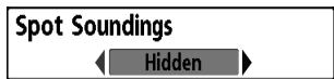
SPOT SOUNDINGS
Spot Soundings allows you to display or hide spot
soundings, which are depth measurements shown on the chart.
NOTE: Spot Soundings are only available with optional-purchase MMC/SD cards.
To change the Spot Soundings setting:
- Highlight Spot Soundings on the Navigation main menu.
- Use the LEFT or RIGHT 4-WAY Cursor Control keys to change the Spot Soundings setting. (Hidden, Visible, Default = Hidden)
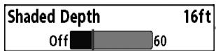
SHADED DEPTH
Shaded Depth allows you to change the depth
used for shading on the chart views.
To change the Shaded Depth setting:
- Highlight Shaded Depth on the Navigation main menu.
- Use the LEFT or RIGHT 4-WAY Cursor Control keys to change the Shaded Depth setting. (Off, 1 to 60 Feet or 1 to 20 Meters [International Units Only], Default = 15 ft, 5 m)
Set Simulation Position
SET SIMULATION POSITION
(Advanced)
Set Simulation Position allows you to set the position of the boat used in the Simulator.
To set the Simulation Position:
- Activate the cursor and move it to the coordinates from where you want simulation to start.
NOTE: The cursor must be active in order for this procedure to work. - Make sure you are in Advanced User Mode, then highlight Set Simulation Position on the Navigation main menu.
- Use the RIGHT 4-WAY Cursor Control key to change the Simulation Position setting. A confirmation dialog box will appear to allow you to change your mind, or to confirm your choice. If the cursor was not active before you began this procedure, you will see an error message. Exit the menu, set the cursor, then try again.
Set Map Offset
SET MAP OFFSET
(Advanced)
Set Map Offset allows you to change the map offset used by the 900 Series™.
NOTE: The Map Offset will be applied to all maps and not just the map that requires the correction. The Map Offset should be cleared if a different map is to be used.
To change the Map Offset setting:
- Activate the cursor and move it location where the Map Offset will be applied.
NOTE: The cursor must be active in order for this procedure to work. - Make sure you are in Advanced User Mode, then highlight Set Map Offset on the Navigation main menu.
- Use the RIGHT 4-WAY Cursor Control key to set the Map Offset. A confirmation dialog box will appear to allow you to change your mind, or to confirm your choice. If the cursor was not active before you began this procedure, you will see an error message. Exit the menu, set the cursor, then try again.
Clear Map Offset
CLEAR MAP OFFSET
(Advanced)
Clear Map Offset allows you to clear the Map Offset. Clear Map Offset is only accessible if a Map Offset is currently active.
To Clear Map Offset:
- Make sure you are in Advanced User Mode, then highlight Clear Map Offset on the Navigation main menu.
- Use the RIGHT 4-WAY Cursor Control key to clear the Map Offset.
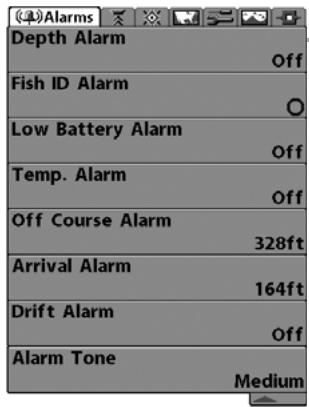
Alarms Menu
ALARMS MENU TAB
From any view, press the MENU key twice to access the Main Menu System. The Alarms tab will be the default selection.
NOTE: When an alarm is triggered, you can silence it by pressing any key. The alarm will be silenced, and will not be triggered again until a new instance of the alarm condition is detected.
| Depth Alarm | Off | |
| Off | 100 | |
DEPTH ALARM
Depth Alarm sounds when the depth becomes
equal to or less than the menu setting.
To change the Depth Alarm setting:
- Highlight Depth Alarm on the Alarms main menu.
- Use the LEFT or RIGHT 4-WAY Cursor Control keys to change the Depth Alarm setting. (OFF, 1 to 100 feet, or 0.5 to 30 meters [International models only], Default = OFF)
| Fish ID Alarm |
| ←○→ |
FISH ID ALARM
Fish ID Alarm sounds when the 900 Series™
detects fish that correspond to the alarm setting. Fish ID Alarm will only sound if Fish ID^+^TM is on.
For example, if you've set the Fish ID Alarm to sound for Large fish only, the Fish ID alarm will sound when a large-sized fish is detected.
To change the Fish ID Alarm setting:
- Highlight Fish ID Alarm on the Alarms main menu.
- Use the LEFT or RIGHT 4-WAY Cursor Control keys to change the Fish ID Alarm setting. (Off, All, Large/Medium, Large, Default = Off)
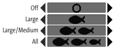
| Low Battery Alarm | Off | |
| Off | 13.5 | |
LOW BATTERY ALARM
Off 13.5 Low Battery Alarm sounds when the input battery voltage is equal to or less than the menu setting. The battery alarm will only sound for the battery that is connected to the 900 Series™. The Low Battery Alarm should be set to warn you when the battery voltage drops below the safety margin that you have determined. For instance, if you are running a trolling motor (battery operated), you would want to set the Low Battery Alarm to sound before the battery voltage drops too low for it to be used to start your main, gasoline-powered engine.
To change the Low Battery Alarm setting:
- Highlight Low Battery Alarm on the Alarms main menu.
- Use the LEFT or RIGHT 4-WAY Cursor Control keys to change the Low Battery Alarm setting. (Off, 9.0V - 13.5V, Default = Off)
| Temp. Alarm | Off |
| Off | 120 |
TEMP ALARM
detected by the 900 Series™ reaches the Temp Alarm setting, which is either set in degrees Fahrenheit or Celsius [International models only]. For example, if the Temp Alarm is set to 58^ Fahrenheit, and the water temperature falls from 60^ to 58^ , the Temp Alarm will sound. Similarly, if the water temperature rises from 56^ to 58^ , the Temp Alarm will also sound.
To change the Temp Alarm setting:
- Highlight Temp Alarm on the Alarms main menu.
- Use the LEFT or RIGHT 4-Way Cursor Control keys to change the Temp Alarm setting. (Off, 32-120 [Fahrenheit], 0-50 [Celsius [International models only]], Default = Off)
| Off Course Alarm | 328ft |
| Off | 3000 |
OFF COURSE ALARM
(With 937c DF Combo and 937c Combo models only)
Off Course Alarm sounds when the boat has moved too far off course based on the menu setting when navigating. Off Course Alarm allows you to set how far the boat is allowed to move off course before the Off Course Alarm will sound.
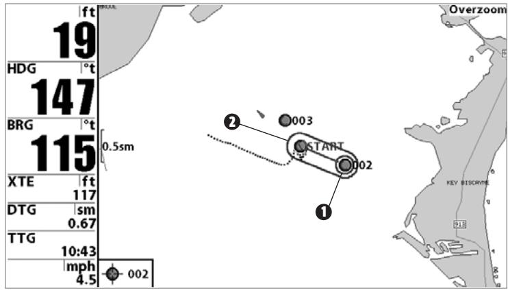
1 Arrival Alarm Circle
Off Course Limits 2
To change the Off Course Alarm setting:
- Highlight Off Course Alarm on the Alarms main menu.
- Use the LEFT or RIGHT 4-WAY Cursor Control keys to change the Off Course Alarm setting. (Off, 30 to 3000 feet, 10 to 1000 meters [International models only], Default = 300 ft, 100 m)
| Arrival Alarm | 164ft |
| Off | 3000 |
ARRIVAL ALARM (With 937c DF Combo and 937c Combo models only)
Arrival Alarm sounds when the boat has either exceeded the distance to the destination waypoint, or has entered the Arrival Alarm Circle, based on the menu setting when navigating. Arrival Alarm allows you to set how close the boat must be to the destination waypoint before the Arrival Alarm will sound.
To change the Arrival Alarm setting:
- Highlight Arrival Alarm on the Alarms main menu.
- Use the LEFT or RIGHT 4-WAY Cursor Control keys to change the Arrival Alarm setting. (Off, 30 to 3000 feet, 10 to 1000 meters [International models only], Default = 150 ft, 50 m)
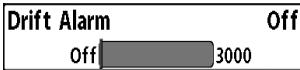
DRIFT ALARM
(With 937c DF Combo and 937c Combo models only)
Drift Alarm sounds when the boat has exceeded the distance from the boat's anchored position, based on the menu setting. Drift Alarm allows you to set the size of a perimeter around the boat's anchored position; if the anchored boat drifts outside of that perimeter, the Drift Alarm will sound.
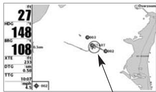
Drift Alarm Circle
To change the Drift Alarm setting:
- Highlight Drift Alarm on the Alarms main menu.
- Use the LEFT or RIGHT 4-WAY Cursor Control keys to change the Drift Alarm setting. (Off, 30 to 3000 feet, 10 to 1000 meters [International models only], Default = Off)
Alarm Tone
Medium
ALARM TONE
Alarm Tone selects the pitch of the alarm sound. A
brief tone will be produced as you adjust the Alarm Tone so that you can select the tone that you can hear best.
To change the Alarm Tone setting:
- Highlight Alarm Tone on the Alarms main menu.
- Use the LEFT or RIGHT 4-WAY Cursor Control keys to change the Alarm Tone setting. (High, Medium, Low, Default = Medium)
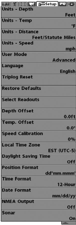
Setup Menu
SETUP MENU TAB
From any view, press the MENU key twice to access the tabbed Main Menu System, then press the RIGHT cursor key until the Setup tab is selected.
NOTE: Menu choices will vary depending on system settings such as whether the unit is set for Advanced User mode and what accessories are attached to the control head.
Units - Depth

UNITS - DEPTH
Units - Depth selects the units of measure for all
depth-related readouts.
To change the Units - Depth setting:
- Highlight Units - Depth on the Setup menu.
- Use the LEFT or RIGHT 4-WAY Cursor Control keys to change the Units - Depth setting. (Meters [International models only], Feet, Fathoms; Default is Meters for International models, and Feet for Domestic models)
Units - Temp

UNITS - TEMP
(International only)
Units - Temp selects the units of measure for all temperature-related readouts. International models only.
To change the Units - Temp setting:
- Highlight Units - Temp on the Setup menu.
- Use the LEFT or RIGHT 4-WAY Cursor Control keys to change the Units - Temp setting. (Celsius, Fahrenheit; Default = Celsius)
Units - Distance
Feet/Statute Miles
UNITS - DISTANCE
(With Speed input only)
Units - Distance selects the units of measure for all distance-related readouts.
To change the Units - Distance setting:
- Highlight Units - Distance on the Setup menu.
- Use the LEFT or RIGHT 4-WAY Cursor Control keys to change the Units - Distance setting. (Domestic Models: Statute Miles, Nautical Miles; Default = Statute Miles; International Models: Meters/Kilometers, Meters/Nautical Miles, Feet/Statute Miles, Feet/Nautical Miles; Default = Meters/Kilometers)
Units - Speed
mph
UNITS - SPEED
(With Speed input only)
Units - Speed selects the units of measure for speed-related readouts.
To change the Units - Speed setting:
- Highlight Units - Speed on the Setup menu.
- Use the LEFT or RIGHT 4-WAY Cursor Control keys to change the Units - Speed setting. (kph [International models only], mph, kts, Default = kph for International models and mph for Domestic models)
User Mode
Advanced
USER MODE
User Mode sets the menu system to either
Normal or Advanced. When set to Normal, only the basic menu options are shown. When set to Advanced (default setting), additional menu choices are available.
To change the User Mode setting:
- Highlight User Mode on the Setup menu.
- Use the LEFT or RIGHT 4-WAY Cursor Control keys to change the User Mode setting. (Normal, Advanced, Default = Advanced)
Language
English
LANGUAGE
(International Only)
Language selects the display language for menus. International models only.
To change the Language setting:
- Highlight Language on the Setup menu.
- Use the LEFT or RIGHT 4-WAY Cursor Control keys to change the Language setting. (Default = English)
Triplog Reset
TRIPLOG RESET
With Speed Input Only
Triplog Reset resets the Triplog to zero. The Triplog provides the following information: timer for elapsed time, distance traveled since last reset, and average speed.
To Reset Triplog:
- Highlight Reset Triplog on the Setup menu.
- Use the RIGHT 4-WAY Cursor Control key to initiate Triplog Reset.
- The Confirm dialog box will appear. To reset the Triplog, press the RIGHT Cursor key once more. To cancel Reset Triplog, press the LEFT Cursor key.
Restore Defaults
RESTORE DEFAULTS
Restore Defaults resets ALL menu settings to their
factory defaults. Use this menu choice with caution!
Select Readouts SELECT READOUTS (Advanced) Select Readouts allows you to customize the information displayed in individual digital readouts on the left side of many views, including suppressing a particular readout so that nothing is displayed; the ability to customize readouts depends on the view and whether you are navigating. This Advanced feature allows you to select what data will be displayed in each of 5 fixed-position data windows arranged at the left edge of the Sonar View screen, or whether a particular data window will be turned off, displaying nothing in that area; you can access this menu choice only when in Advanced User Mode (see Setup Menu Tab:User Mode.)
Data windows can display readouts from supported accessories such as a Speed accessory. Each data window can either be empty (Off) or contain one of the following:
- Heading - Temperature
- Depth
- Time + Date
- Position - Triplog
Voltage Water Speed (only with a Speed accessory) - Speed (if there is a GPS Receiver, then this refers to the speed detected by the GPS Receiver; if no GPS Receiver, then this refers to the speed of the paddlewheel)
Sonar-only Views, Not Navigating: On Sonar-only views, as long as you are not navigating, all 5 readouts are customizable.
Other Views, Not Navigating: On any view with a chart, as long as you are not navigating, two of the readouts are not customizable: the 2nd box always displays Heading, while the 5th box always displays Speed. On the Bird's Eye View, when you
are not navigating, there are four fixed info boxes that show Depth, Heading, Position (Lat/Lon) and Speed. When you are navigating in the Bird's Eye View, there are two columns of four boxes. The first column shows Depth, Time To Go (TTG), Position (Lat/Lon), and Speed. The second column shows Cross Track Error (XTE), Heading, Bearing, and Distance To Go (DTG).
All Views, Navigating: When you are navigating, all readouts in all views (even split screen views with a Sonar display) cannot be customized, with the exception of the top readout info box, which is still customizable. In any view, while you are navigating, the second readout box shows Heading, the third box shows Bearing, the fourth box is divided to show Cross Track Error (XTE) and Distance To Go (DTG), and the fifth box is divided to show Time To Go (TTG) and Speed.
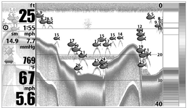
Default Sonar View
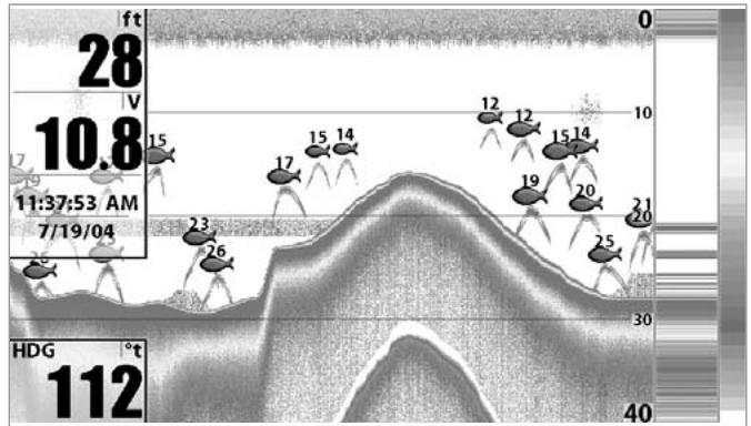
Customized Sonar View
To Select Readouts:
- Make sure you are in Advanced User Mode, then highlight Select Readouts on the Setup main menu.
- Use the RIGHT 4-WAY Cursor Control key to initiate this procedure.
- The Select Readouts submenu will appear, showing a list of all Readouts. Use the UP or DOWN Cursor keys to select a particular Readout position, then use the RIGHT or LEFT Cursor keys to change what will be displayed at that position. (Heading, Depth, Navigation, Position, Off, Speed, Temperature, Time+Date, Triplog, Voltage, Water Speed)
| Depth Offset | 0.0ft |
| -10.0 | 10.0 |
DEPTH OFFSET
(Advanced)
Depth Offset will adjust the digital depth readout to indicate depth from the waterline or boats keel. Enter a positive vertical measurement from the transducer to the waterline to read the depth from the waterline. Enter a negative vertical measurement from the transducer to keel to read the depth from the keel. This menu choice is available only when in Advanced User Mode (see Setup Menu Tab: User Mode.)
To change the Depth Offset setting:
- Make sure you are in Advanced User Mode, then highlight Depth Offset on the Setup menu.
- Use the LEFT or RIGHT 4-WAY Cursor Control keys to change the Depth Offset setting. (-10.0 to +10.0 feet or -3 to 3 meters [International models only], Default = 0.0, or Off)
| Temp. Offset | 0.0° |
| -10.0 | 10.0 |
TEMP OFFSET
(Advanced)
Temp Offset will adjust the temperature readout by the amount entered. This menu choice is available only when in Advanced User Mode (see Setup Menu Tab: User Mode.)
To change the Temp Offset setting:
- Make sure you are in Advanced User Mode, then highlight Temp Offset on the Setup menu.
- Use the LEFT or RIGHT 4-WAY Cursor Control keys to change the Temp Offset setting. (-10.0 to +10.0 degrees, Default = 0.0, or Off)
| Speed Calibration | 0% |
| -20 | 20 |
SPEED CALIBRATION
(Advanced, with Speed paddle wheel only)
Speed Calibration will adjust the speed readout by the percentage entered, and will appear in the menu if a Speed accessory is connected and the paddlewheel has moved at least once, when the unit is in Advanced User Mode (see Setup Menu Tab: User Mode.)
To change the Speed Calibration setting:
- Make sure you are in Advanced User Mode, then highlight Speed Calibration on the Setup menu.
- Use the LEFT or RIGHT 4-WAY Cursor Control keys to change the Speed Calibration setting. (-20%) to +20% , Default = 0% .
Local Time Zone
EST (UTC-5)
LOCAL TIME ZONE
(Advanced, with 937c DF Combo and 937c Combo models only)
Local Time Zone selects your time zone in reference to the time reported by the GPS receiver when Time+Date is selected as a Digital Readout on the Sonar View (see Select Readouts). This menu choice is available only when in Advanced User Mode (see Setup Menu Tab: User Mode.)
To change the Local Time Zone:
- Make sure you are in Advanced User Mode, then highlight Local Time Zone on the Setup menu.
- Use the LEFT or RIGHT 4-WAY Cursor Control keys to change the Local Time Zone (Default = EST [UTC-5] - Eastern Standard Time).
Daylight Saving Time
Off
(Advanced, with 937c DF Combo and 937c Combo models only)
Daylight Saving Time adjusts the time display to account for local Daylight Saving Time. Selecting On adds one hour to the time display adjusted for your local time zone. Selecting Off leaves the time display as adjusted for your local time zone. This menu choice is available only when in Advanced User Mode (see Setup Menu Tab: User Mode.)
To change the Daylight Saving Time setting:
- Make sure you are in Advanced User Mode, then highlight Daylight Saving Time on the Setup menu.
- Use the LEFT or RIGHT 4-WAY Cursor Control keys to turn Daylight Saving Time On or Off. (Off, On, Default = Off)
Position Format
dd'mmm.mmm
POSITION FORMAT
(Advanced, with 937c DF Combo and 937c Combo models only)
Position Format selects the format of the latitude and longitude position display. This menu choice is available only when in Advanced User Mode (see Setup Menu Tab: User Mode.)
To change the Position Format setting:
- Make sure you are in Advanced User Mode, then highlight Position Format on the Setup menu.
- Use the LEFT or RIGHT 4-WAY Cursor Control keys to change the Position Format. (dddddd°, dd'mm.mm', or dd'mm'ss", Default = dd'mm.mm')
Time Format
2-Hour
TIME FORMAT
(Advanced)
(937c DF Combo and 937c Combo Models, International Only)
Time Format changes the time format used by the unit. This menu choice is available only when in Advanced User Mode (see Setup Menu Tab: User Mode.) International models only. Time Format selects a 12 hour or 24 hour format for the time of day displayed when Time + Date is selected as a Digital Readout on the Sonar View (see Select Readouts).
To change the Time Format:
- Make sure you are in Advanced User Mode, then highlight Time Format on the Setup menu.
- Use the LEFT or RIGHT 4-WAY Cursor Control keys to change the Time Format. (12 hour, 24 hour, Default = 12 hour)
Date Format
m/dd/yy
DATE FORMAT
(Advanced)
(937c DF Combo and 937c Combo Models, International Only)
Date Format changes the date format used by the unit This menu choice is available only when in Advanced User Mode (see Setup Menu Tab: User Mode.) International models only. Date Format selects the format for the date display when Time + Date is selected as a Digital Readout on the Sonar View. (see Select Readouts).
To change the Date Format:
- Make sure you are in Advanced User Mode, then highlight Date Format on the Setup menu.
- Use the LEFT or RIGHT 4-WAY Cursor Control keys to change the Date Format. (mm/dd/yy, dd.mm.yy or yy.mm.dd, Default = mm/dd/yy)
NMEA Output
Off
NMEA OUTPUT
(Advanced)
NMEA Output turns the NMEA output on or off. This menu choice is available only when in Advanced User Mode (see Setup Menu Tab: User Mode.)
The following NMEA sentences are output:
DPT-Depth
MTW - Water Temperature
GLL - Lat/Lon Position
GGA-GPS Fix Data
RMC - Recommended Minimum Specific GNSS Data
VTG - Course Over Ground and Ground Speed
ZDA-Time and Date
When navigating, the following NMEA sentences are also output:
APB - Autopilot Sentence B
BWR - Bearing and Distance to Waypoint
RMB - Recommended Minimum Navigation Info
To turn NMEA Output on or off:
- Make sure you are in Advanced User Mode, then highlight NMEA Output on the Setup menu.
- Use the LEFT or RIGHT 4-WAY Cursor Control keys to change the NMEA Output to On or Off (Off, On, Default = Off).
Sonar
On
SONAR
(937c DF Combo and 937c Combo models only)
Sonar deactivates Sonar and removes the Sonar Views from the view rotation.
To turn Sonar on or off:
- Highlight Sonar on the Setup menu.
- Use the LEFT or RIGHT 4-WAY Cursor Control keys to change the Sonar to On or Off (Off, On, Default = On).
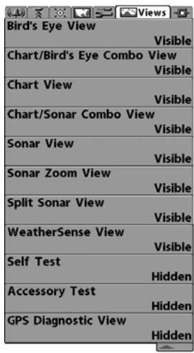
Views Menu
VIEWS MENU TAB
From any view, press the MENU key twice to access the tabbed Main Menu System, then press the RIGHT 4-WAY Cursor Control key until the Views tab is selected. This menu tab allows you to set the available views to either hidden or visible in the view rotation. The view will be removed from the view rotation if it is set to Hidden and will be displayed in the view rotation if it is set to Visible. The following views are available:
Bird's Eye View
(937c DF Combo and 937c Combo models only)
Chart/Bird's Eye Combo View
(937c DF Combo and 937c Combo models only)
Chart View
(937c DF Combo and 937c Combo models only)
Chart/Sonar Combo View
(937c DF Combo and 937c Combo models only)
- Sonar View
- Sonar Zoom View
- Split Sonar View
(937c DF Combo/931c DF models only)
Self Test
- Accessory Test
- GPS Diagnostic View
(937c DF Combo and 937c Combo models only).
To Change the View Status of Any View:
- Highlight the View main menu tab.
- Use the UP or DOWN 4-WAY Cursor Control keys to select a View.
- Use the LEFT or RIGHT 4-WAY Cursor Control keys to change the status of the view from Hidden to Visible or vice versa.
ACCESSORIES MENU TAB
From any view, press the MENU key twice to access the tabbed Main Menu System, then press the RIGHT cursor key until the Accessories tab is selected.
If no accessories are attached to the Accessory Bus, no menu choices will appear under the Accessories tab. If an accessory is attached, however, additional menu choices that support the accessory will be added automatically. See the Operations Manual that comes with your accessory for detailed information.
Accessories Menu
(no accessories attached)
Accessories Menu
(with accessories attached)
NOTE: Accessories to enable WeatherSense® and the SmartCast® Wireless Sonar Link (WSL) require separate purchases. You can visit our website at www.humminbird.com or contact our Customer Resource Center at 1-800-633-1468 for additional details.
TROUBLESHOOTING
Before contacting the Humminbird® Customer Resource Center, please read the following section. Taking the time to review these troubleshooting guidelines may allow you to solve a performance problem yourself, and therefore avoid sending your unit back for repair.
900 Series™ Doesn't Power Up
If your 900 Series™ doesn't power up, use the Installation Guide that also comes with it for specific confirmation details, making sure that:
- the power cable is properly connected to the 900 Series™ control head,
- the power cable is wired correctly, with red to positive battery terminal and black to negative terminal or ground
the fuse is operational - the battery voltage of the power connector is at least 10 Volts.
Correct any known problems, including removing corrosion from the battery terminals or wiring, or actually replacing the battery if necessary.
900 Series™ Defaults to Simulator with a Transducer Attached
A connected and functioning transducer will cause the newly-started 900 Series™ to go into Normal operating mode automatically. If, when you power up the 900 Series™, it goes into Simulator mode automatically, even though a transducer is already connected, this means that the control head is not detecting the transducer. Perform the following troubleshooting tasks:
- Using the Installation Guide that also comes with your 900 Series™, check to make sure that the transducer cable is securely connected to the 900 Series. Reconnect if necessary, and power up the 900 Series™ again to see if this fixes the problem.
- Replace the non-functioning transducer with a known good transducer if available and power up the control head again.
- Check the transducer cable. Replace the transducer if the cable is damaged or corroded.
DISPLAY PROBLEMS
There are several main conditions or sources of possible interference that may cause problems with the quality of the information displayed on the control head. Look in the following table for some symptoms of display problems and possible solutions:
| Problem | Possible Cause |
| The control head loses power at high speeds. | If the power output of your boat's engine is unregulated, the control head may be protecting itself using its over-voltage protection feature. Make sure the input voltage does not exceed 20 Volts. |
| When the boat moves at higher speeds, the bottom disappears or suddenly weakens, or the display contains gaps. | The transducer position may need to be adjusted. A mix of air and water flowing around the transducer (cavitation) may be interfering with the interpretation of sonar data. See your Installation Guide for suggestions on adjusting the transducer position. |
| Electrical noise from the boat's engine may be interfering with sonar reception. See Finding the Cause of Noise for more information. | |
| There are no fish detected, even when you know they are in the water under the boat, or sonar readings seem weak or faulty. | Sonar readings may be affected if the transducer is not positioned correctly (i.e. mounted at an angle, not straight down), or there is some kind of mechanical interference, either because it is mounted inside a hull that is too thick for proper sonar transmission, the bond between the transducer and the hull is not airtight, or because the transducer is dirty. Check with your Installation Guide for guidance on re-positioning the transducer, and make sure the transducer is clean. |
| Low battery voltage may be affecting the power of signal transmission. | |
| Electrical noise from the boats engine may be interfering with sonar reception. See Finding the Cause of Noise for more information. |
FINDING THE CAUSE OF NOISE
Electrical noise usually affects the display with many black dots at high speeds, and high sensitivity readings. One or more of the following sources can cause noise or interference:
| Possible Source of Noise | Isolation |
| Other electronic devices | Turn off any nearby electronic devices to see if the problem goes away, then turn them on one at a time to see if the noise re-appears. |
| The boat's engine | To determine whether the boat's engine is the source of the noise, increase the RPMs while the boat is in neutral and stationary to see if the noise increases proportionately; if noise appears when you rev the engine, the problem could be the spark plugs, alternator, or tachometer wiring. Replace the spark plugs with resistor plugs, install an alternator filter, or route the control head power and transducer cables away from the engine wiring. |
| Cavitation from the boat's propeller | Turbulence created by the propeller can cause noise; make sure the transducer is mounted at least 15” (38 cm) from the propeller, and that the water flows smoothly over the face of the transducer at all times. |
1-YEAR LIMITED WARRANTY
We warrant the original retail purchaser that products made by Humminbird® have been manufactured free from defects in materials and workmanship. This warranty is effective for one year from the date of original retail purchase. Humminbird® products found to be defective and covered by this warranty will be replaced or repaired free of charge at Humminbird®'s option and returned to the customer freight prepaid. Humminbird®'s sole responsibility under this warranty is limited to the repair or replacement of a product that has been deemed defective by Humminbird®. Humminbird® is not responsible for charges connected with the removal of such product or reinstallation of replaced or repaired parts.
This warranty does not apply to a product that has been:
- Improperly installed;
- Used in an installation other than that recommended in the product installation and operation instructions;
- Damaged or has failed because of an accident or abnormal operation;
- Repaired or modified by entities other than Humminbird®.
Please retain your original receipt as a proof of the purchase date. This will be required for in-warranty service.
THIS WARRANTY IS EXPRESSLY IN LIEU OF ANY OTHER WARRANTYES, OBLIGATIONS OR LIABILITIES ON THE PART OF HUMMINBIRD® AND WILL BE THE CUSTOMER'S EXCLUSIVE REMEDY, EXCEPT FOR ANY APPLICABLE IMPLIED WARRANTYES UNDER STATE LAW WHICH ARE HEREBY LIMITED IN DURATION TO ONE YEAR FROM THE DATE OF ORIGINAL PURCHASE. IN NO EVENT WILL HUMMINBIRD® BE LIABLE FOR ANY INCIDENTAL OR CONSEQUENTIAL DAMAGES FOR BREACH OF ANY EXPRESS OR IMPLIED WARRANTY RELATING TO THE PRODUCTS.
Some states do not allow limitations on an implied warranty, or the exclusion of incidental or consequential damages, so the above exclusions may not apply to you. You may also have other rights, which vary from state to state.
HUMMINBIRD® SERVICE POLICY
Even though you'll probably never need to take advantage of our incredible service policy, it's good to know that we back our products this confidently. We do it because you deserve the best. We will make every effort to repair your unit within three business days from the receipt of your unit at our factory. This does not include shipping time to and from our factory. Units received on Friday are typically shipped by the following Wednesday, units received Monday are typically shipped by Thursday, etc.
All repair work is performed by factory-trained technicians to meet exacting factory specifications. Factory-serviced units go through the same rigorous testing and quality control inspections as new production units.
After the original warranty period, a standard flat rate service charge will be assessed for each repair (physical damage and missing parts are not included). Any repairs made after the original warranty will be warranted for an additional 90 days after service has been performed by our factory technicians. You can contact our Customer Resource Center or visit our website to verify the flat rate repair fee for your product (visit the Product Support section):
http://www.humminbird.com
We reserve the right to deem any product unserviceable when replacement parts are no longer available or impossible to obtain. This Service Policy is valid in the United States only. This applies only to Humminbird® products returned to our factory in Eufaula, Alabama. This Service Policy is subject to change without notice.
RETURNING YOUR UNIT FOR SERVICE
Before sending your unit in for repair, please contact the factory, either by phone or by email, to obtain a Repair Authorization Number for your unit. Please have your product model name and serial number available before calling the factory. If you contact the factory by e-mail, please include your product model name and serial number in the e-mail, and use Request for Repair Authorization Number for your e-mail subject header. You should include your Repair Authorization Number in all subsequent communications about your unit.
For IN-WARRANTY service, complete the following steps:
- Obtain a Repair Authorization Number from the Humminbird® Customer Resource Center.
- Tag product with your name, street address, phone number and your assigned Repair Authorization Number.
- Include a brief written description of the problem.
- Include a copy of your receipt (to show proof and date of purchase).
- Return product freight prepaid to Humminbird®, using an insured carrier with delivery confirmation.
For OUT-OF-WARRANTY service, complete the following steps:
- Obtain a Repair Authorization Number from the Humminbird® Customer Resource Center.
- Include payment in the form of credit card number and expiration date, money order or personal check. Please do not send cash.
- Tag product with your name, street address, phone number and your assigned Repair Authorization Number.
- Include a brief written description of the problem.
- Return product freight prepaid to Humminbird®, using an insured carrier with delivery confirmation.
900 SERIES™ ACCESSORIES
Accessories customize the 900 Series™ to your needs and enable you to stay on the edge of new technology. When an accessory is connected to the 900 Series™, additional menus and readouts are added automatically to the Main Menu System. Accessories available today that are supported by your 900 Series™ include:
WeatherSense® Fishing Condition Monitor: purchase and plug in the WeatherSense® accessory to your 900 Series™ to obtain barometric pressure readouts and trend data in real time.
GPS Connection Cable: purchase the GPS Connection Cable in order to connect a handheld or other NMEA* GPS-compatible device that you may already own to your 900 Series™.
*NMEA 0183 is a National Marine Electronics Association standard for data communication.
Wireless Sonar Link (WSL): purchase the Wireless Sonar Link (WSL) accessory to receive remote sonar signals from a SmartCast® Remote Sonar Sensor (RSS). Radio signals from the RSS are received by the WSL and are transmitted over the Accessory Bus to the 900 Series™.
Be sure to check out our website www.humminbird.com for additional new and exciting accessories to grow your 900 Series™.
NOTE: Each accessory requires a separate purchase. You can visit our website at www.humminbird.com or contact our Customer Resource Center at 1-800-633-1468 for additional details.
SPECIFICATIONS
Depth Capability
937c DF Combo/931c DF 2500 ft (780 m)
937c Combo/931c 1000 ft (330 m)
Power Output
937c DF Combo/931c DF. 1000 Watts (RMS), 8000 Watts (Peak to Peak)
937c Combo/931c 750 Watts (RMS), 6000 Watts (Peak to Peak)
Operating Frequency
937c DF Combo/931c DF 200 kHz and 50 kHz DualBeam PLUS™
937c Combo/931c 200 kHz Single Beam
Area of Coverage
937c DF Combo/931c DF. 74^ @-10 dB in 50 kHz & 20^ @-10 dB in 200 kHz
937c Combo/931c 20° @ -10 dB in 200 kHz
Target Separation 2½ Inches (63.5 mm)
Power Requirement 10-20 VDC
LCD. 480V x 854H
Transducer
937c DF Combo/931c DF (Dual frequency) XHS-9-DB-74-T
937c Combo/931c (Single frequency) XHS-9-20-T
Transducer Cable Length 20 ft (6 m)
NOTE: Product specifications and features are subject to change without notice.
NOTE: Humminbird® verifies maximum stated depth in saltwater conditions, however actual depth performance may vary due to transducer installation, water type, thermal layers, bottom composition and slope.
APPENDIX A
Transducer Mounting Template, Single frequency: XHS-9-20-T
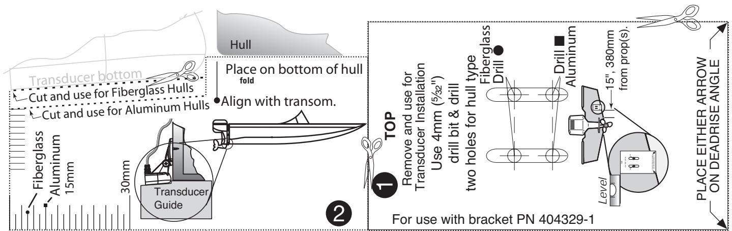
APPENDIX B
Transducer Mounting Template, Dual frequency: XHS-9-DB-74-T
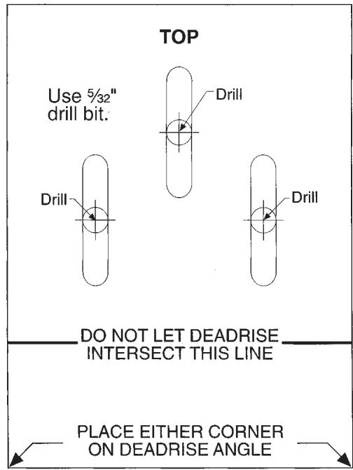
Remove and use for Transducer Installation
Contact Humminbird
Contact the Humminbird® Customer Resource Center in any of the following ways:
By Telephone
(Monday - Friday 8:00 a.m. to 4:30 p.m. Central Standard Time):
1-800-633-1468
By e-mail
(typically we respond to your e-mail within three business days):
custserv@johnsonoutdoors.com
For direct shipping, our address is:
Humminbird®
Service Department
678 Humminbird Lane
Eufaula, AL 36027 USA

HUMMINBIRD®