800 - Fish Finder HUMMINBIRD - Free user manual and instructions
Find the device manual for free 800 HUMMINBIRD in PDF.

User questions about 800 HUMMINBIRD
0 question about this device. Answer the ones you know or ask your own.
Ask a new question about this device
Download the instructions for your Fish Finder in PDF format for free! Find your manual 800 - HUMMINBIRD and take your electronic device back in hand. On this page are published all the documents necessary for the use of your device. 800 by HUMMINBIRD.
USER MANUAL 800 HUMMINBIRD
800 Series ^™ and 900 Series ^™
Thank You!
Thank you for choosing Humminbird ^® , the #1 name in fishfinders. Humminbird ^® has built its reputation by designing and manufacturing top-quality, thoroughly reliable marine equipment. Your Humminbird ^® is designed for trouble-free use in even the harshest marine environment. In the unlikely event that your Humminbird ^® does require repairs, we offer an exclusive Service Policy - free of charge during the first year after purchasing and available at a reasonable rate after the one-year period. For complete details, see the separate warranty card included with your unit. We encourage you to read this manual carefully in order to get full benefit from all the features and applications of your Humminbird ^® product.
Contact our Customer Resource Center at either 1-800-633-1468 or visit o Web site at humminbird.com.
WARNING! The electronic chart in your Humminbird® unit is an aid to navigation designed to facilitate the use of authorized government charts, not to replace them. Only official government charts and notices to mariners contain all of the current information needed for the safety of navigation, and the captain is responsible for their prudent use.
WARNING! This device should not be used as a navigational aid to prevent collision, grounding, boat damage, or personal injury. When the boat is moving, water depth may change too quickly to allow time for you to react. Always operate the boat at very slow speeds if you suspect shallow water or submerged objects.
WARNING! Disassembly and repair of this electronic unit should only be performed by authorized service personnel. Any modification of the serial number or attempt to repair the original equipment or accessories by unauthorized individuals will void the warranty.
WARNING! This product contains chemicals known to the State of California to cause cancer and/or reproductive harm.
WARNING! Do not travel at high speed with the unit cover installed. Remove unit cover before traveling at speeds above 20 mph.
WARNING! Humminbird® is not responsible for the loss of data files (waypoint routes, tracks, groups, recordings, etc.) that may occur due to direct or indirect damage to the unit's hardware or software. It is important to back up your co-read's data files periodically. Data files should also be saved to your PC before restoring the unit's defaults or updating the software. See the following sections: your Humminbird® manual: Snapshot and Recording View and SD Memory Card Slots. Also, contact our Customer Resource Center with any questions.
NOTE: Some features discussed in this manual require a separate purchase, an some features are only available on international models. Every effort has been made to clearly identify those features. Please read the manual carefully in order understand the full capabilities of your model.
NOTE: To purchase accessories for your control head, visit our web site at humminbird.com or contact our Customer Resource Center at 1-800-633-1468.
NOTE: The procedures and features described in this manual are subject to which without notice. This manual was written in English and may have been translated to another language. Humminbird ^® is not responsible for incorrect translations or discrepancies between documents.
NOTE: The illustrations in this manual may not look the same as your product your unit will function in the same way.
NOTE: The following accessories are not compatible with your unit: CannonLink™, InterLink™, Remote Sonar Link™ (RSL), SmartCast®, WeatherSense®, and XM WX Satellite Weather®. See our Web site at humminbird.com for the latest compatibility information.
ATTENTION INTERNATIONAL CUSTOMERS: Products sold in the U.S. are not intended for use in the international market. Humminbird® international units provide international features and are designed to meet country and regional regulations. Languages, maps, time zones, units of measurement, and warranty are examples of features that are customized for Humminbird® international units purchased through our authorized international distributors.
To obtain a list of authorized international distributors, please visit our Web site at humminbird.com or contact our Customer Resource Center at (334) 687-6613.
800 Series™, 900 Series™, Cannon®, CannonLink™, Contour XD™, Down Imaging®, DualBeam PLUSTM, Fish ID+™, HumminbirdPC™, Humminbird®, InterLink™, LakeMaster®, ProMap™, One-Touch® Zoom, QuadraBeam PLUSTM, RTS Window™, Side Imaging®, SmartCast®, SwitchFire®, Structure ID™, Total Screen Update™, UniMap™, WeatherSense®, WhiteLine™, X-Press™ Menu, and Xtreme Depth Series™ are trademarked by or registered trademarks of Johnson Outdoors Marine Electronics, Inc.
Adobe, Acrobat, Adobe PDF, and Reader are either registered trademarks or trademarks of Adobe Systems Incorporated in the United States and/or other countries.
Baekmuk Batang, Baekmuk Dotum, Baekmuk Gulim, and Baekmuk Headline are registered trademarks owned by Kim Jeong-Hwan.
Navionics ^® Gold, HotMaps ^™ , and HotMaps ^™ Premium, Navionics ^® Classic Charts, and Platinum ^™ Cartography are trademarked by or registered trademarks of Navionics ^® .
NMEA 2000 ^® is a registered trademark of the National Marine Electronics Association.
XM® WX is a registered trademark of XM Satellite Radio and Weather to the Power of X® is a registered trademark of XM Satellite Radio Inc. All rights reserved.
© 2014 Johnson Outdoors Marine Electronics, Inc. All rights reserved.
Table of Contents
Introduction 1
How Sonar Works ....1
DualBeam PLUS™ Son®DualBeam PLUS™ models only [859ci HD, 899ci HD SI, 959ci HD, and 999ci...HD...SI])....3
Down Imaging® Son(Brown Imaging® models only (859ci HD DI and 959ci...HD...DI))
High Definition Side Imaging® Square Imaging® models only [899ci HD SI and 999ci HD...SI]....4
Xtreme Depth Sonaktreme Depth Series™ models [859ci HD XD and 959ci HD.4XD])
QuadraBeam PLUS™ Son with optional-purchase QuadraBeam PLUS™ transducer5
Universal Sonar (compatible w/optional-purchase Minnkota trolling motors)......5
How GPS and Cartography Work 5
Fishing System Configuration....7
RS 232 Connect(000 Series™ only)....7
Ethernet Connector 8
Power On 8
What's on the Control Head 9
Key Functions 9
POWER/LIGHT Key 9
VIEW Key 10
MENU Key 10
4-WAY Cursor Control Key (RIGHT, LEFT, UP, or DOWN Cursor Keys) ......
VIEW PRESET Keys ....11
EXIT Key 11
INFO Key 11
MARK Key....11
GOTO Key 12
ZOOM (+/-) Keys 12
SD Memory Card Slots 12
Add Maps to Your Fishing System 13
Import Navigation Data....13
Export Navigation Data 13
Update Software 15
What's on the Sonar Display
Understanding the Sonar Display....17
Real Time Sonar (RTS ^TM ) Window ....1
Sonar Colors and Bottom View....18
SwitchFire ^® 19
Freeze Frame and Active Cursor 19
Instant Image Update ....19
What's on the Side Imaging® Display
(Side Imaging® models only [899ci HD SI and 999ci HD SI]) 20
Understanding the Side Imaging® Display 2
Side Imaging® Frequencies and Coverage....22
For Best Performance 23
On the Water Interpretation 24
Table of Contents
What's on the Down Imaging® Display
(859ci HD DI, 959ci HD DI, 899ci HD SI, and 999ci HD SI a)
Understanding the Down Imaging® Display 27
Interpreting the Display 27
Down Imaging® Sensitivity 27
Freeze Frame and Active Cursor 27
Views 28
Sonar View 29
Sonar Zoom View....30
Split Sonar View 31
Side Imaging® Vie(999ci HD SI and 999ci HD SI .only)....32
Down Imaging® View859ci HD DI, 959ci HD DI, 899ci HD SI and 999ci HD...SB4only)
Snapshot and Recording V(+optional-purchase SD Memory card required)......35
Side Beam View with optional-purchase QuadraBeam PLUS™ transducer)....40
Bird's Eye View....42
Chart View 43
Combo Views 44
Combo Views: Functions 44
Side Imaging®/Sonar Combo Vi899ci HD SI and 999ci HD SI...only.....44
Chart/Bird's Eye Combo View 45
Chart/Chart Combo View 45
Chart/Sonar Combo View 46
Chart/Side Imaging® Combo Vi699ci HD SI and 999ci HD SI...only)....46
Down Imaging®/Side Imaging® Combo Vaseci HD SI and 999ci HD SI...only...47
Chart/Down Imaging® Combo View
(859ci HD DI, 959ci HD DI, 899ci HD SI and 999ci HD...SI...only)....47
27 Down Imaging®/Sonar Combo View
(859ci HD DI, 959ci HD DI, 899ci HD SI, and 999ci HD...SI...only)....48
Down Imaging®/Side Imaging®/Sonar Combo (989ci HD SI and 999ci HD SI...ABly)
View Orientation 49
Viewing Cartography 49
Introduction to Navigation 51
Waypoints, Routes, and Tracks....51
Open the Waypoint Management Dialog Box ....5
What's on the Waypoint Management Dialog Box ....
Save, Edit, or Delete a Waypoint ....54
Navigate to a Waypoint or Position 55
Add a Waypoint Target or Trolling Grid 55
Routes....56
Tracks 57
Edit your Waypoints, Routes, Tracks, and Groups......
Man Overboard (MOB) Navigation....60
The Menu System 61
Start-Up Options Menu 61
Normal 61
Simulator 62
System Status 62
Table of Contents
Self Test 62
Accessory Test 63
GPS Diagnostic View 63
X-Press™ Menu 64
Main Menu 64
Quick Tips for the Main Menu 65
Note for all Menu Settings 65
User Mode (Normal or Advanced) 66
Sonar X-Press™ Menu 67
Cancel Navigation(only when Navigating)....67
Active Side(Combo Views only)....67
Split Position(Combo Views only)....67
Sensitivity 68
Upper Range(Advanced: Sonar, Split Sonar and Active Sonar Side Views...only)...68
Lower Range 69
Chart Speed 69
Quad Layout (with optional-purchase QuadraBeam PLUS™ Transducer, Side Beam View...on!69
Bottom LockSonar Zoom View only....70
Bottom Range(Sonar Zoom View only, when Bottom Lock...is...On)....70
Side Imaging ^® X-Press ^TM Menu
(Side Imaging® Views only [899ci HD SI, 999ci HD SI]) 70
Cancel Navigation(only when Navigating)....71
Active SideCombo Views only.....71
Split PositionCombo Views only)....71
SI Side....71
SI Sensitivity....71
SI Enhance 72
SI Range 72
Chart Speed 73
SI Colors 73
Down Imaging ^® X-Press ^TM Menu
(Down Imaging ^® Views only [859ci HD DI, 959ci HD DI, 899ci HD SI, and 999ci HD SI]) 73
Cancel Navigation only when Navigating.....74
Active SideCombo Views only)....74
Split Position(Combo Views only)....74
Down Sensitivity 74
DI Enhance 74
Upper Range(Advanced, Down Imaging® Views only)....75
Lower Range 75
Chart Speed 76
DI Colors 76
Navigation X-Press™ Menu 76
Cancel Navigation only when Navigating.....77
Cancel MOB Navigation only when MOB Navigation is activated.....77
Table of Contents
Skip Next Waypoint only when Navigating.....77
Active SideCombo Views only 77
Split Position(Combo Views only)....77
Waypoint [Name]Only with an active cursor on a waypoint....78
Cursor to Waypoint Chart or Chart Combo View only 78
Chart Declutter....78
Save Current Track....78
Clear Current Track 78
Save Current Routely when Navigating.....79
Reset XTF[only when Navigating]....79
Remove Target only if a Target is Active....79
Remove Grid only if a Grid is Active....79
Waypoint [Name]Most recently-created waypoint....79
Snapshot and Recording X-Press™ Menu
(Snapshot and Recording View only) 80
Cancel Navigation(only when Navigating)....80
Start Recording (optional-purchase SD Memory Card, Snapshot and Recording View...only.....80
Stop Recording(optional-purchase SD Memory Card only) 80
Delete Image(optional-purchase SD Memory Card, Snapshot and Recording View8 only)
Delete All Images (optional-purchase SD Memory Card, Snapshot and Recording View...only.....81
Delete Recording (optional-purchase SD Memory Card, Snapshot and Recording View...only.....81
Delete All Recordings (optional-purchase SD Memory Card, Snapshot and Recording View...only).....81
Pings Per Second (optional-purchase SD Memory Card, Snapshot and Recording View...only)......81
Playback Speed (optional-purchase SD Memory Card, Snapshot and Recording View...only).....82
Stop Playback(optional-purchase SD Memory Card only) 82
Alarms Menu Tab 83
Depth Alarm 83
Fish ID Alarm 83
Low Battery Alarm 84
Aux. Temp Alarm with optional-purchase temp. probe or Temp/Speed...only.....84
Temp. Alarm 84
Off Course Alarm 84
Arrival Alarm 85
Drift Alarm 85
Alarm Tone 85
Timer Setup 86
Start Timer 86
Stop Time(with the Timer running) 86
Sonar Menu Tab 87
Beam Select 87
Imaging Frequency(859ci HD DI, 959ci HD DI, 899ci HD SI, and 999ci HD...SI...80ly)
Surface Clutter 89
Table of Contents
SwitchFire ^® 89
Fish ID+TM 90
Fish ID Sensitivity....90
Real Time Sonar (RTS™) Window
Sonar Colors....91
Bottom View....91
Zoom Width(Sonar Zoom View only) 92
50 kHz Sensitivity Advanced, XD Sonar only [859ci HD XD and 959ci...HQ...XD].....92
83 kHz Sensitivity Advanced, DualBeam PLUS™ Sonar only [859ci HD, 959ci HD, 899ci HD SI, 999ci HD, SI]....92
455 kHz Sensitivity Advanced, Down Imaging® Views only [859ci HD DI, 959ci...H2 DI])
455 kHz Sensitivity Advanced, with optional-purchase QuadraBeam PLUS™ transd(82er)
Depth Lines(Advanced) 93
SI Range Line Advanced, Side Imaging® View only [899ci HD SI and 999ci..HD93SI]
SI ReadoutsAdvanced, Side Imaging® View only f899ci HD SI and 999ci...HD...S94
Noise Filter(Advanced)....94
Max Depth(Advanced)....94
Water Type(Advanced) 95
Digital Depth Source Advanced, Down Imaging ^® models with optional-purchase transducers only [859ci HD DI and 959ci..HD..DI].....95
Connected Transducer....96
DI Pings/Advanced, Down Imaging® View and Chart/Down Combo View...only.....96
Color Bar....97
Temperature Graph(Sonar View only, with Temperature input)....97
DI Color(859ci HD DI, 959ci HD DI, 899ci HD SI and 999ci HD...SI...only).....97
Down Imaging ^® Beam WideAdvanced, 899ci HD SI and 999ci HD SI...only.....97
Navigation Menu Tab 98
Current Track 98
Waypoints, Routes, TrackWaypoint Management Dialog Boxl....99
Waypoint Settings 99
Saved Tracks Defaults 99
Chart Orientation 100
Casting Rings 100
North Reference....100
Waypoint Proximity Flag(Advanced)....100
Waypoint Decluttering(Advanced)....101
Trolling Grid Rotation....101
Trackpoint Interval 101
Track Min Distance(Advanced)....101
Track Color Range 101
Map Datum(Advanced)....102
North-Up Indicator....102
Course Projection Line....102
3D View Outline 102
Continuous Navigation Mode....102
SI Navigation(Side Imaging ^® models only [899ci HD SI and 999ci...HD...SI]).....102
Table of Contents
Chart Menu Tab 103
Lat/Lon Grid 103
Navaids on Bird's Eye View....103
Chart Select 103
Set Simulation Position(Advanced) 104
Set Map Offs(Advanced)....104
Clear Map Offs(Advanced)....104
Shaded Depth 104
Chart Detail Level 104
Map Borders....106
Spot Soundings ....106
Auto Zoom(Advanced)....106
Auto Range(Advanced) 106
Vessel Offset(Advanced)....106
Offset Speedwith Vessel Offset turned onl....107
Contour Line optional-purchase LakeMaster ^® charts only....107
Depth Color(optional-purchase LakeMaster® charts only)....107
Depth Highlightoptional-purchase LakeMaster® charts only.....107
Depth Highlight Range (+/bptional-purchase LakeMaster ^® charts only)......107
Water Level Offsptional-purchase LakeMaster® charts only)....107
Shallow Water Highlightoptional-purchase LakeMaster® charts only.....108
Lake Listoptional-purchase LakeMaster® charts only.....108
Setup Menu Tab 109
Units - Depth 109
Units - Tem(International Models only)....109
Units - Distance(with Speed input only)....109
Units - Speed with Speed input only.....110
User Mode 110
Language (International Models only)....110
Triplog Reset(with Speed input only)....110
Restore Defaults....110
Format Nav Directories 110
Select Readout(Advanced) 111
Depth Offset(Advanced) 112
Aux. Temp Offs Advanced, with Temp/Speed only)....112
Temp. Offset(Advanced) 112
Speed Calibration|Advanced, with Temp/Speed only|......112
Local Time Zor(Advanced) 112
Daylight Saving Time(Advanced) 112
Position Format(Advanced)....112
GPS Output....113
Time Format(Advanced, International Models only)....113
Date Format(Advanced, International Models only)....113
Digits Format(Advanced)....113
NMEA 0183 Output(Advanced) 113
Local Sonar....114
Table of Contents
Demonstration 114
Sound Control 114
Views Menu Tab 115
Accessories Menu Tab 115
Screen Snapshot(optional-purchase SD Memory Cards only)....116
AIS (optional-purchase AIS equipment only)....116
Maintenance 119
Troubleshooting 120
Fishing System Doesn't Power Up 120
Fishing System Defaults to Simulator with a Transducer Attached 120
Display Problems 121
Finding the Cause of Noise....122
Specifications 123
Glossary 127
Appendix A
Side Imaging® Transducer Mounting Template (XHS 9 HD SI 18032T)
Contact Humminbird ^® 133
NOTE: Entries in this Table of Contents which list (International Only) are only available on products sold outside of the U.S. by our authorized international distributors. To obtain a list of authorized international distributors, please visit our Web site at humminbird.com or contact our Customer Resource Center at (334) 687-6613.
NOTE: Some of the entries in this Table of Contents may require the purchase of separate accessories. You can visit our Web site at humminbird.com to order these accessories online or contact our Customer Resource Center at 1-800-633-1468.
Introduction
How Sonar Works
Your Humminbird ^® Fishing System comes in several different configurations. Sonar technology is based on sound waves. The Fishing System uses so. See the following list of products, all of which are covered by this manual, locate and define structure, bottom contour and composition, as well find your 800/900 Series ^™ configuration: depth directly below the transducer.
- Humminbird® 859ci HD Combo: Wide screen Fishing System with DualBeam PLUS™ Sonar, Chartplotting, and an internal GPS Receiver
- Humminbird® 859ci HD DI Combo: Wide screen Fishing System with Down Imaging® Sonar, Traditional 2D Sonar, Chartplotting, and an internal GPS Receiver.
- Humminbird® 859ci HD XD Combo: Wide screen Fishing System with Xtreme Depth Sonar, Chartplotting, and an internal GPS Receiver.
- Humminbird® 899ci HD SI Combo: Wide screen Fishing System with Side Imaging® Sonar, DualBeam PLUS™ Sonar, Down Imaging® Sonar Chartplotting, and an internal GPS Receiver.
- Humminbird® 959ci HD Combo: Ultra wide screen Fishing System with DualBeam PLUS™ Sonar, Chartplotting, and an internal GPS Receiver.
- Humminbird® 959ci HD DI Combo: Ultra wide screen Fishing System with Down Imaging® Sonar, Traditional 2D Sonar, Chartplotting, and an internal GPS Receiver.
- Humminbird® 959ci HD XD Combo: Ultra wide screen Fishing System with Xtreme Depth Sonar, Chartplotting, and an internal GPS Receive
- Humminbird® 999ci HD SI Combo: Ultra wide screen Fishing System with Side Imaging® Sonar, DualBeam PLUS™ Sonar, Down Imaging® Sonar, Chartplotting, and an internal GPS Receiver.
Sonar is very fast. A sound wave can travel from the surface to a dept 240 ft (70 m) and back again in less than 1/4 of a second. It is unlike your boat can "outrun" this sonar signal.
SONAR is an acronym for SOund and NAVigation Ranging. Sonar utilizes precision sound pulses or "pings" which are emitted into the water in a teardrop-shaped beam.
The sound pulses "echo" back from objects in the water such as the bottom, fish and other submerged objects. The returned echoes are displayed on the LCD screen. Each time a new echo is received, the old echoes are moved across the LCD, creating a scrolling effect.
When all the echoes are viewed side by side, an easy to interpret "graph" of the bottom, fis and structure appears.
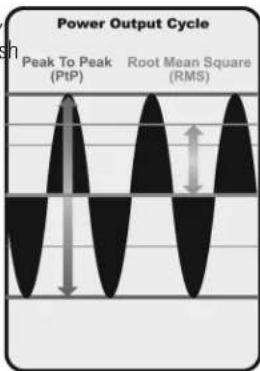
The power output is the amount of energy generated by the sonar transmitter. It is commonly measured using two methods:
- Root Mean Square (RMS) measures power output over the entire transmit cycle.
- Peak to Peak measures power output at the highest points.
The benefits of increased power output are the ability to detect smaller targets at greater distances, ability to overcome noise, better high speed performance and enhanced depth capability.
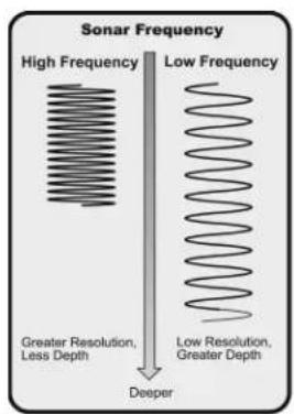
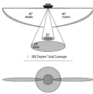
The sound pulses are transmitted at various frequencies depending on the application. Very high frequencies (455 kHz) are used for greatest definition, but the operating depth is limited. High frequencies (200 kHz) are commonly used on consumer sonar and provide a good balance between depth performance and resolution. Low frequencies (83 kHz) are typically used to achieve greater depth capability.
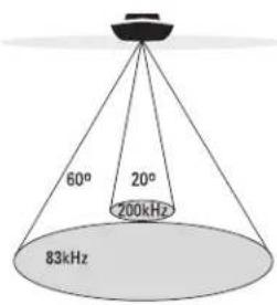
60 Degree Total Coverage
Bottom Coverage = 1 x Depth
DualBeam PLUS™ Sonar
(DualBeam PLUS™ models only [859ci HD, 899ci HD SI, 959ci HD, & 999ci
The 859ci HD/959ci HD Combo and 899ci HD SI/999ci HD SI Combo Fishing Systems use a 200/83 kHz DualBeam PLUS™ sonar system with a wide (60°) area of coverage. DualBeam PLUS™ sonar has a narrowly focused 20° center beam, surrounded by a second beam of 60°, expanding your coverage to an area equal to your depth. In 20 feet of water, the wider beam covers an area 20 feet wide.
DualBeam PLUS™ sonar returns can be blended together, viewed separately, or compared side-by-side. DualBeam PLUS™ is ideal for a wide range of conditions - from shallow to very deep water in both fresh salt water. Depth capability is affected by such factors as boat speed, wave action, bottom hardness, water conditions, and transducer installation.
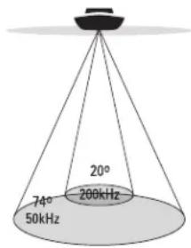
75 Degree Total Coverage
Bottom Coverage = 1 x Depth
Down Imaging® Sonar
(Down Imaging ^® models only [859ci HD DI and 959ci HD DI])
The 859ci HD DI/959ci HD DI Combo Fishing System uses Down Imaging® technology. The Down Imaging® transducer scans the water with razor-thin, high-definition beams. The beams are wide (side to side) but very thin front to back.
The Down Imaging® beams can be operated at two frequencies: 455 kHz (75°) or 800 kHz (45°). Select 455 kHz for the best overall image quality and depth. Select 800 kHz for the sharpest image. See Down Imaging® X-Press™ Menu: Imaging Frequency for more information.
The transducer also uses conical beams to provide data in traditional 2D format (see What's on the Sonar View). Select 455 kHz for a narrow focused 16° center beam, or select 200 kHz for a wider 28° beam (see Menu Tab: Beam Select).
Depth capability is affected by such factors as boat speed, wave action, bottom hardness, water conditions, and transducer installation.
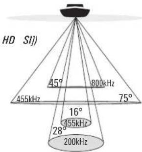
High Definition Side Imaging® Sonar
(Side Imaging ^® models only [899ci HD SI and 999ci HD SI only])
The 899ci HD SI/999ci HD SI Combo Fishing System uses Side Imaging® sonar to provide a wide yet precise survey of a large area of water, including detailed bottom topography and fish-attracting structure orientation. The Side Imaging® transducer returns are processed into an image similar to an aerial photograph.
Typically, the Side Imaging ^® sonar can search an area that is 480 feet wide (240 to each side), with a typical depth performance of 150 feet when the Side Imaging ^® Sonar frequency is set for 455 kHz. Selecting 800 kHz (999ci HD SI only) produces the sharpest image, but the search area to each side and the depth capability are limited as compared to the 455 kHz frequency. See What's on the Side Imaging ^® Display and Understanding Side Imaging ^® for more information.
The Side Imaging ^® transducer also provides Down Imaging ^® views on the screen, with the same depth limitation of 100 feet. See What's on the Down Imaging ^® Display for more information.
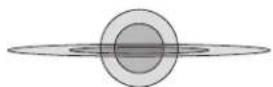
74 Degree Total Coverage
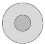
natural_image
Two concentric circles with no text or symbols, no visible text or symbols.Xtreme Depth Sonar
(Xtreme Depth Series™ models only [859ci HD XD and 959ci HD XD])
The 859ci HD XD/959ci HD XD Combo Fishing System uses the XD transducer to provide extreme depth coverage with DualBeam PLUS™ technology.
The Xtreme Depth sonar beams can be operated at two frequencies: 50 kHz (74°) and 200 kHz (20°). The wide, 50 kHz beam transmits at a low frequency to provide greater depth coverage, up to 2500 ft (762 m). The narrow, 200 kHz center beam transmits at a high frequency to provide maximum detail at shallower depths.
The DualBeam PLUS™ technology allows you to view the sonar returns blended together, separately, or side-by-side (see Sonar Menu Tab: Beam Select and Views for more information).
Depth capability is affected by such factors as boat speed, wave action, bottom hardness, water conditions, and transducer installation.
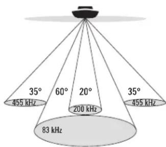
90° Total Coverage
Bottom Coverage=2 x Depth
QuadraBeam PLUS™ Sonar
(with optional-purchase QuadraBeam PLUS™ transducer)
QuadraBeam PLUS™ sonar provides a wide 90° area of coverage.
QuadraBeam PLUS™ starts with two fan-shaped 35° 455 kHz Side Structure locating sonar beams to spot fish, bait, and structure to the left and right of boat over an area of the bottom that's always equal to twice your depth.
For a detailed view below the boat, QuadraBeam PLUS™ uses DualBeam PLUS™ technology, with precision 20° and wide 60° beams. QuadraBeam PLUS™ finds more fish faster, and can even tell you where to put your bait by showing if fish are to the left, right, or directly beneath your boat.
NOTE: Contact our Customer Resource Center to determine which accessory transducers are compatible with your Humminbird™ Fishing System, or visit our Web site athumminbird.com.
Universal Sonar 2
(compatible w/optional-purchase Minnkota trolling motors)
Your Fishing System supports Universal Sonar 2, a state-of-the-art, integrated and protected transducer that is built into the lower unit of Minnkota trolling motors. With Universal Sonar 2, all wiring is concealed inside the indestructible composite shaft—out of sight and out of harm's way, with no clamps, ties, or exposed wires. Universal Sonar 2 features temperature sensing and the performance of DualBeam PLUS™ technology (available with all Humminbird® DualBeam PLUS™ models). An expanded view and greater bottom detail gives you a totally new perspective of the water below, along with optimal sonar performance to help you find fish
How GPS and Cartography Work
Your Fishing System also supports GPS (Global Positioning System) and chartplotting. It uses GPS and sonar to determine your position, display i a grid, and provide detailed underwater information.
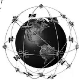
natural_image
Diagram of Earth surrounded by a globe with orbital lines and satellite constellations (no text or labels)GPS uses a constellation of satellites that continually send radio signals to the earth. The GPS receiver receives signals from satellites that are visible to it. Based on time differences between each received signal, the GPS receiver determines its distance to each satellite. With distances known, the GPS receiver mathematically triangulates its own position. With 5 updates per second, the GPS receiver then calculates its velocity and bearing.
GPS was originally intended for military use; however, civilians may also take advantage of its highly accurate position capabilities, typically within +/- 4.5 meters, depending on conditions. This means that 95% of the time, the GPS receiver will read a location within 4.5 meters of your actual position. Your GPS Receiver also uses information from WAAS (the Wide Area Augmentation System), EGNOS (the European Geostationary Navigation Overlay Service), and MSAS (the MTSAT Satellite Augmentation System) satellites if they are available in your area.
The following GPS functionality is currently supported by the Fishing System:
• View current position
• View current track (breadcrumbs trail)
• View precision speed and heading from your GPS receiver
- Save tracks, waypoints, and routes
- Travel a route and navigate from one waypoint to the next.
See Chart View and SD Memory Card Slots: Add Maps to Your Fishing System for more information.
The Fishing System has a wide variety of configurations
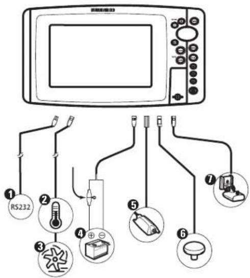
① RS 232 (900 Series™ only)
② Temperature (900 Series™ only)
3 Speed (900 Series™ only)
4 Power
NMEA 2000° Module 5
GPS Receiver 6
Sonar Transducer with Temperature 7
Fishing System Configuration
RS 232 Connector (900 Series™ only)
The Fishing System has a wide variety of configurations that will influence the installation. The RS 232 connector (900 Series™ only) allows you to expand with optional-purchase equipment such as AIS (Automatic your Fishing System capabilities. As you expand the configuration, the certification System).
options that correspond with the connected accessory will be added to the menu system.
Please read all instructions that are relevant for your configuration before beginning the installation process. See the Humminbird® installation guide details.
NOTE: The following accessories are not compatible with your unit: CannonLink™, InterLink™, Remote Sonar Link™ (RSL), SmartCast®, WeatherSense®, and XM WX Satellite Weather®. See our Web site at humminbird.com for the latest compatibility information.
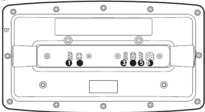
① RS 232 (900 Series™ only)
Ethernet 4
② Temp/Speed (900 Series™ only)
COM (communications) 5
3 Power
Transducer 6
NOTE: Accessories connected to the RS 232 connector require a separate power source.
NOTE: To purchase a connection cable for an optional-purchase AIS, visit our Web site at humminbird.com or contact our Customer Resource Center at 1-800-633-1468.
Ethernet Connector
Your unit has a built-in Ethernet connector so that you can network two Humminbird® units. When you connect the units together using the optional-purchase Humminbird® Ethernet cable, data is shared across the two units and additional menu options are added to the Menu System. See the Ethernet Operations Manual for details.
NOTE: The Ethernet cable requires a separate purchase. Visit our Web site at humminbird.com or contact our Customer Resource Center at 1-800-633-1468 for details.
Power On
Follow the instructions below to power on your Humminbird® control head.
999ci HD SI Combo Title Screen
-
Press the POWER/LIGHT key to power on your Humminbird® control head.
-
When the Title screen is displayed, press the MENU key to access the Start-Up Options Menu.
-
If a functioning transducer is connected, Normal operation will be selected automatically, and your Fishing System can be used on the water. See Start-Up Options Menu for more information.
- If a transducer is not connected and you wait too long to select a Start-Up Option, the system will default to whichever menu is already highlighted.
- You can also select Simulator to learn how to use your control head and save settings in advance for later use.
- Quick Setup: If this is the first time the unit has been powered or (after installation or after restoring defaults), the Quick Setup dialog box will display on the screen. Use the 4-WAY Cursor Control key set the Language, Water Type, and Max Depth. Press the EXIT key to close the dialog box.
NOTE: The Quick Setup settings can be changed at any time. See each menu option in The Menu System for details.
What's on the Control Head
Key Functions
Your Fishing System user interface is easy to use. A combination of keyYour Fishing System has a set of easy to use keys that give you flexibii different views, and situation-specific, customizable menus allows you to control over your fishing experience.
control what you see on the color display. Refer to the following illustration,
and see Key Functions, Views, and The Menu System for more information.
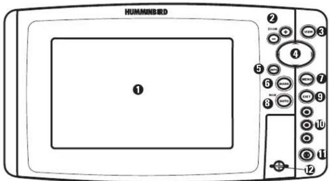
① Screen
Menu Key 7
② ZOOM (+/-) Keys
GOTO Key 8
③ View Key
Exit Key 9
4 4-Way Cursor Control Key
VIEW PRESET Keys 10
5 Info Key*
Power/Light Key 11
6 MARK Key
SD Card Slot 12
*Your control head will have one of the INFO keys shown here. Both keys function in the same way.

POWER/LIGHT Key
The POWER/LIGHT key is used to power the Fishing System on and off. You can also use the POWER/LIGHT key to adjust the backlight and contrast of the display.
Power On: Press the POWER/LIGHT key to power on the unit. When this screen is displayed, press the MENU key to access the Start-Up Options Menu.
Power Off: Press and hold the POWER/LIGHT key for 3 seconds. A mes: will appear to indicate how many seconds there are until shutdown occur. To ensure that shutdown occurs properly and any menu settings will be saved, your Fishing System should always be turned off using the POWER/LIGHT key.
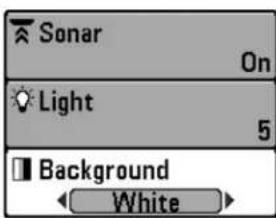
Adjust the Backlight or the Display Background Color: Press the POWER/LIGHT key to access the Light and Background submenu. Use the 4-WAY Cursor Control key to select Light or Background, and then use the LEFT or RIGHT Cursor key to change the settings. Press EXIT to exit the Light and Background submenu.
NOTE: Your control head will start up with the backlight on and will automatically turn it off to conserve power.
Turn Local Sonar On or Off: From the Light and Background submenu, use the 4-WAY Cursor Control key to select Local Sonar. Use the LEFT or RIGHT Cursor key to change the setting. See Setup Menu Tab: Local Sonar for more information.
NOTE: This feature may appear as either Sonar or Local Sonar, depending on your model.

VIEW Key
The VIEW key is used to cycle through all available views. Press the VIEW key to advance to the next view. Press the VIEW key repeatedly to cycle through all available views. Views can be hidden to optimize the system to your fishing requirements (see Views or Views Menu Tab).

MENU Key
The MENU key is used to access the menu system. See The Menu System for more information.
Start-Up Options Menu: Press the MENU key during the power up sequence to view the Start-Up Options menu.
X-Press™ Menu: Press the MENU key once in any view to access the X-Press™ Menu, which provides frequently-used menu settings that correspond with the current view or navigation mode.
Main Menu: Press the MENU key twice in any view to access the Main Menu, which is organized under tabbed headings to help you find a specific menu item quickly.
4-WAY Cursor Control Key
(RIGHT, LEFT, UP, or DOWN Cursor Keys)
The 4-WAY Cursor Control key has multiple functions, which depend on the view, menu, or situation.
- Menu Selection: Press the DOWN or UP Cursor keys to highlight a menu option, then press the RIGHT or LEFT Cursor keys to change menu setting. The changes will be activated and saved immediately.
- Freeze Frame: In Sonar View, Side Imaging® View, and Down Imaging® View press any arrow on the 4-WAY Cursor Control key to freeze the display and move the active cursor to a location on the screen. A cursor dialog box will display to show the depth of the location you choose.
- Active Cursor: Press any arrow on the 4-WAY Cursor Control key, a the active cursor will appear on the screen.
- Chart Views: The 4-WAY Cursor Control key also pans the charts a highlights decluttered waypoint icons.
NOTE: In Freeze Frame or Active Cursor mode, you can also make the cursor move diagonally by pressing in between two of the arrows on the 4-WAY Cursor Control key.
- Bird's Eye View: The 4-WAY Cursor Control key controls the motion of the eye point.
- Snapshot and Recording View: Press the UP or DOWN Cursor keys to highlight a recording icon, and then press the RIGHT Cursor key fic start recording playback. Press the RIGHT or LEFT Cursor keys to control the speed of playback.
VIEW PRESET Keys
The VIEW PRESET keys are used to save your three favorite views for quick retrieval. Instead of using the VIEW key to cycle through all the views to find the one you want, you program the VIEW PRESET keys to display a specific view immediately. See Views for more information.

INFO Key
Press the INFO key while in Bird's Eye, Chart, or Combo V to display information about objects that are near an active cursor. If the cursor is not active, the Chart Info submenu be displayed. See Views: Viewing Cartography for more information.
NOTE: Your control head will have one of the INFO keys shown here. Both keys function in the same way.

EXIT Key
The EXIT key has multiple functions, which depend on the situation:
- If an alarm is sounding, press the EXIT key to cancel the alarm.
- If a menu tab is selected, press the EXIT key to exit the menu mode and return to the view.
- If a menu is active, press the EXIT key to return to the previous level in the menu system.
- From any view, press the EXIT key to cycle through the available views in reverse order.
- If Freeze Frame is active, press the EXIT key to return to a scrolling display.
- If the Cursor is active, press the EXIT key to remove the cursor from the display.

MARK Key
Press the MARK key while in any view to mark the position a waypoint. The MARK key function is available if the GPS receiver is connected.
Active Cursor: The waypoint will be marked at the cursor location.
- Without Active Cursor: The waypoint will be marked at the boat location.
- If Screen Snapshot is active, a waypoint will be created, and a screen snapshot will also be saved to the optional-purchase SD card (see Views: Snapshot and Recording View). Navigation is not affected by the Screen Snapshot feature.
NOTE: If Screen Snapshot is enabled but there is not a GPS receiver connected, pressing the MARK key will capture the screen image and display an error saying that a GPS position fix is required to create a waypoint.
NOTE: You must have an optional-purchase SD card installed for the screen snapshot feature to work.

GOTO Key
The GOTO key has multiple functions, which depend on the situation.
- Active Cursor: Press the GOTO key while in any view to create a waypoint and start navigation towards that waypoint.
- Without Active Cursor: Press the GOTO key to display the saved waypoints list, and then highlight a waypoint. Press the RIGHT Cursor key to begin navigation.
- Man Overboard: Press and hold the GOTO key for more than 1.5 seconds to activate the Man Overboard (MOB) function. Once MOB is activated, any current navigation will be cancelled and the current route will be discarded without notification (see Man Overboard (MOB) Navigation).
natural_image
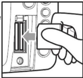
Hand inserting a component into a device panel (no text or symbols visible)Inserting an SD Card into the Card Slot
SD Memory Card Slots
The two SD memory card slots on your control head can be used with SD memory cards (optional-purchase required) to add detailed charts to your Fishing System, update your Fishing System software, or export navigation data from your Fishing System.
NOTE: The SD Memory Cards require a separate purchase. For more information, visit our Web site at humminbird.com or contact our Customer Resource Center at 1-800-633-1468.

ZOOM (+/-) Keys
The Zoom keys function in different ways which depend on the view displayed.
- Navigation Views or the Sonar Zoom View: Press the +/- ZOOM key to change the scale of the view to appear closer or farther away.
- Side Imaging® View or Down Imaging® View: Use the 4-WAY Cursor Control key to move the active cursor to a position on the screen. Press the + ZOOM key to magnify your selection. Press the -Zoom key to decrease the scale.
NOTE: The cursor must be active for the zoom feature to work in the Side Imaging ^® or Down Imaging ^® , View.
To insert an SD memory card:
- Remove the SD memory card slot cover.
- Position the SD memory card so that the label faces the left side of unit, and insert the card into the slot. Press down on the card un clicks into place.
- Close the slot cover and turn the knob just 1/4 of a turn to close. NOT overtighten, as this will not improve water resistance and may damage the cover.
- To Remove: Press the SD memory card into the slot and then release. The card will eject, and you can then pull the card from the slot.
NOTE: Do not leave the SD slot cover open. The slot cover should always be closed to prevent water damage to the unit.
Add Maps to Your Fishing System
Your Fishing System includes a built-in Contour XD ^™ or UniMap ^™ with a more detailed map of North America (Domestic models) or a detailed map of Europe and Southeast Asia, including Australia and New Zealand (International models).
You can also purchase SD memory cards with additional chart information for a particular location.
NOTE: The 800/900 Series™ supports LakeMaster®, Navionics® Gold, HotMaps™, HotMaps™ Premium, and Platinum™ Cartography on SD card media. The 800/900 Series™ does not support Navionics® Classic Charts.
NOTE: The SD Memory Cards require a separate purchase.
- Auto Select: When you install the SD cards in your control head, your Fishing System will retrieve the chart and display it automatically.
- Chart Select: You can also choose which chart to display with the Chart Select menu option in the Chart Menu Tab. Choose Right (card slot) or Left (card slot) to select the SD card you'd like to use (see Chart Menu Tab: Chart Select).
- Chart Layers: You can customize your Navigation Views by selecting which chart layers to display or hide (see Chart Menu Tab: Chart Detail Level).
- Map Borders: Use the 4-WAY Cursor Control key to move the active cursor within a map border, and press the ZOOM + key to view the different map (see Chart Menu Tab: Map Borders).
- Menu Options: The Chart Menu Tab will change to display menu options that correspond with the active chart (see Chart Menu Tab).
Import Navigation Data
Review the following information before importing navigation data (waypoints, routes, tracks, or groups) into your Humminbird® unit.
- Import Humminbird® Navigation Data: Insert a loaded SD card into the control head card slot, and follow the on-screen prompts to import the waypoints, routes, tracks, and groups. In certain models, the data will import automatically.
WARNING! DO NOT import navigation data from unknown sources into your Humminbird® unit without first converting the data to the correct format using HumminbirdPC™. Importing corrupted data can cause the unit to malfunction, which can result in lost navigation data.
NOTE: For more information and instructions, see the FAQ (Frequently Asked Questions) section of our Web site at humminbird.com or call our Customer Resource Center at 1-800-633-1468.
Export Navigation Data
The Humminbird® Waypoint Management dialog box allows you to export of your navigation items to an installed, unlocked SD Card. You can also export selected items.
For more information, see Introduction to Navigation: What's on Waypoint Management Dialog Box. Also, see your Humminbird® Waypoint Management Guide for complete details.
It is important to back up your control head's data files (waypoints, routes, tracks, groups, recordings, etc.) periodically. You can also save, view, and organize your navigation data on your PC using HumminbirdPC™. See your Humminbird® online account for details at humminbird.com.
To export all navigation data:
Use the following instructions to export all of the control head's waypoints, routes, tracks, and groups to an installed, unlocked SD card.
- Insert an unlocked SD card into the SD card slot.
- Open the Waypoint Management Dialog Box: Press the MENU key twice. Press the RIGHT Cursor key until the Navigation tab is selected. Select Waypoints, Routes, Tracks. Press the RIGHT Cursor key.
- Select Options > Select All and... > Export.
- Follow the on-screen instructions to confirm or cancel the export.
To export selected navigation items
Use the following instructions to select and export specific waypoints, routes, tracks, and groups to an installed, unlocked SD card.
- Insert an unlocked SD card into the SD card slot.
- Open the Waypoint Management Dialog Box: Press the MENU key twice. Press the RIGHT Cursor key until the Navigation tab is selected. Select Waypoints, Routes, Tracks. Press the RIGHT Cursor key.
- From a selected group directory in the Waypoint Management dialog box, select Options > Select Multiple and... > Export.
-
Select Items: Press the UP or DOWN Cursor keys to scroll through the waypoints, routes, tracks, and groups. Press the RIGHT Cursor key to select an item. Repeat as needed.
-
Confirm Export: When you are finished selecting items, press the EXIT key to select Export Selected. Press the RIGHT Cursor key and follow the on-screen instructions to confirm or cancel the export.
NOTE: If an SD memory card is not installed, an error message will be displayed, Insert the SD memory card and try again.
NOTE: The SD memory cards and USB Memory Card Reader require separate purchases. The USB Memory Card Reader accessory can be used in conjunction your personal computer to view and organize your exported navigation data. Visit Web site athumminbird.com or contact our Customer Resource Center at 1-800-633-1468 for more information.
Update Software
Set up an online account at humminbird.com so that you will receive the latest Humminbird® news and software upgrades for your Fishing System. You can also download HumminbirdPC™ from your account, which allows you to manage your waypoints, routes, and tracks on your personal computer.
NOTE: It is important to back up your control head's data files (waypoints, routes, tracks, groups, recordings, etc.) periodically. Data files should also be saved to your PC before restoring the unit's defaults or updating the software. See Export Navigation Data and Snapshot and Recording View for more information. Also, contact our Customer Resource Center with any questions.
Required Equipment: Personal computer with Internet access, a formatted SD memory card, and USB Memory Card Reader.
To update the control head software
e1. Install a formatted SD memory card into the card reader connected to your PC.
2. Register your Fishing System: Log on to humminbird.com. Click My Account. Set up a new account.
3. Download: From My Account\My Profile\My Equipment, click the file name of the latest software update (unit name [version #]).
- Read the instructions in the dialog box and click Download.
-
Follow the prompts to save the software file directly to the SD Card.
-
Install the SD card with the updated software file into the control head card slot.
-
Power on your Fishfinder. The control head will recognize the new software and run through a series of prompts to confirm software installation.
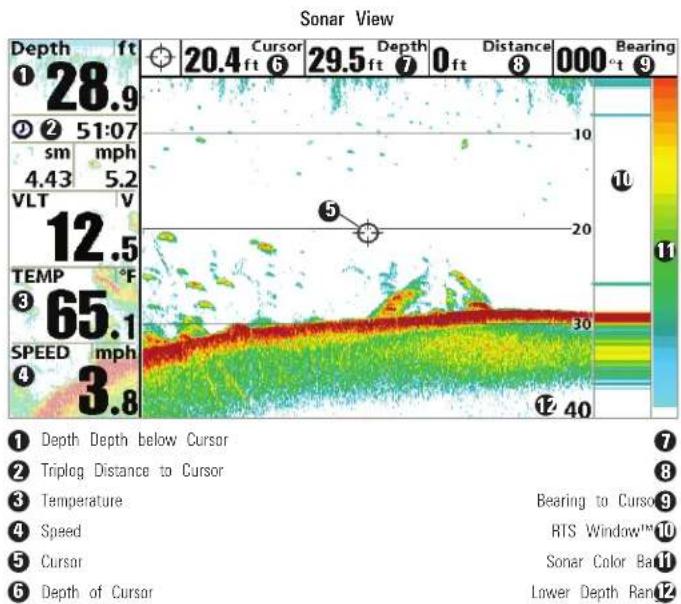
What's on the Sonar Display
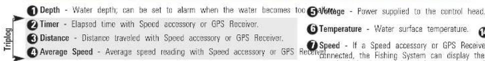
The Fishing System can display a variety of useful information about the area under and adjacent to your boat, including the following items:
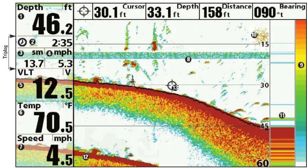
① Depth - Water depth; can be set to alarm when the water becomes too ⑤ A/mage - Power supplied to the control head.
② Timer - Elapsed time with Speed accessory or GPS Receiver. ⑥ Temperature - Water surface temperature.
3 Distance - Distance traveled with Speed accessory or GPS Receiver.
4 Average Speed - Average speed reading with Speed accessory or GPS
7 Speed - If a Speed accessory or GPS Receiver is connected, cursor information is displayed at the top of the Fishing System can display the speed of the boat, and the screen. can keep a trip log of nautical or statute miles traveled.
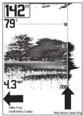
Understanding the Sonar Display
It is important to understand the significance of the display. The display does NOT show a literal 3-dimensional representation of what is under the water. Each vertical band of data received by the control head and plotted on the display represents something that was detected by a sonar return at a particular time. As both the boat and the targets (fish) may be moving, the returns are only showing a particular segment of time when objects were detected, not exactly where those objects are in relation to other objects shown on the display.
The returned sonar echoes are displayed on the screen. As a new echo received, the historical data scrolls left across the display.
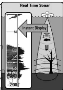
Real Time Sonar (RTS™) Window
A Real Time Sonar (RTS™) Window appears on the right side of the display in the Sonar Views. The RTS Window™ always updates at the fastest rate possible for depth conditions and shows only the returns from the bottom structure and fish that are within the transducer beam. The RTS Window plots the depth and intensity of a sonar return. (See Sonar Menu Tab Time Sonar (RTS™) Window).
The Narrow RTS Window™ indicates the sonar intensity through the use of colors. Red indicates a strong return and blue indicates a weak return. The depth of the sonar return is indicated by the vertical placement of the return on the display depth is scale.
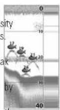
The Wide RTS Window™ indicates the sonar intensity through the use of a bar graph. The length of the plotted return provides an indication of whether the return is weak or strong. The depth of the sonar return is indicated by the vertical placement of the return on the display depth scale.
bar
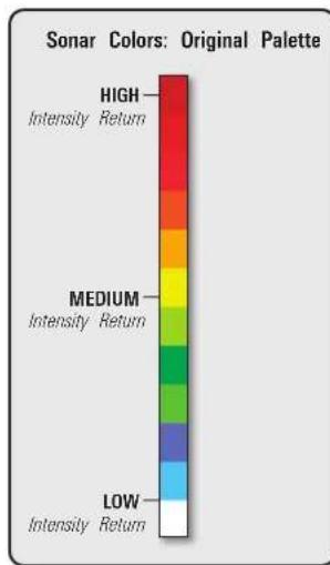
| Sonar | Colors | Original Palette | |-------|--------|-------------------| | HIGH | High | Red | | MEDIUM| Medium | Yellow | | LOW | Low | White |Sonar Colors and Bottom View
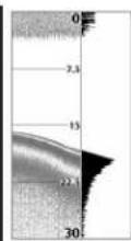
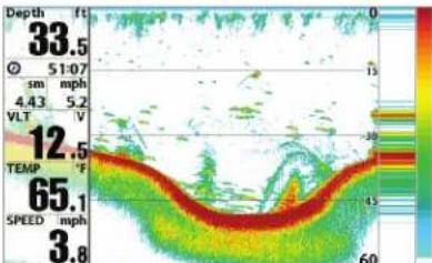
As the boat moves, the unit charts the changes in depth on the display to create a profile of the Bottom Contour. The Sonar View displays the sonar return intensity with different colors.
Strong returns often result from rocky or hard bottoms (compacted sediment, rocks, fallen trees), while weaker returns often result from soft bottoms (sand, mud), vegetation, and small fish.
The colors used to represent high, medium, to low intensity returns are determined by the palette you choose in the Sonar Colors menu option. See Sonar Menu Tab to set the Sonar Colors.
Sonar View: Original Palette
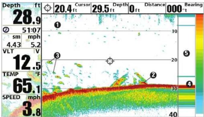
① Sonar History: Historical returns scroll left across the view.
② Strong Returns (possibly rocks, tree limbs, or other structure)
③ Weak Returns (possibly vegetation or small fish)
4 Strong Return (possibly compacted sediment or rocks)
5 RTS Window™
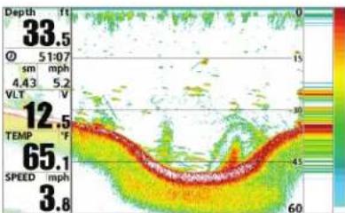
Use Bottom View to select the method used to represent bottom and structure on the display. See Sonar Menu to set the Bottom View.
Structure ID™ represents weak returns in blue and strong returns in resSwitchFire®
when Sonar Colors is set to Original. If the Sonar Colors palette is ch the Structure ID™ will display the strongest return as specified by the palette. See Sonar Menu Tab: Sonar Colors for more information.
heatmap
| Depth (ft) | Value | |---|---| | 33.5 | 0 | | 51:07 | 15 | | 4.43 | 30 | | 5.2 | 35 | | 12.5 | 40 | | 65.1 | 60 | | 3.8 | 65 |WhiteLine™ highlights the strongest sonar returns in white, resulting in distinctive outline. This has the benefit of clearly defining the bottom or display.
heatmap
| Depth (ft) | 33.5 | 12.5 | 65.1 | 3.8 | |---|---|---|---|---| | Ø 51:07 | 4.43 | 5.2 | 65.1 | 3.8 | | VLT | 5.2 | 5.2 | 65.1 | 3.8 | | Temp (°F) | 4.43 | 5.2 | 65.1 | 3.8 | | Speed (mph) | 60 | 45 | 60 | 3.8 | | Velocity (mph) | 15 | 30 | 45 | 60 | The color scale ranges from 0 to 60, likely representing velocity or speed in mph or mph.SwitchFire® controls how the sonar returns are displayed in the Sonar Views. SwitchFire® settings are available in the Sonar Menu Tab.
To see the maximum sonar information available within the transducer be so more fish arches and better jig tracking are shown, choose Max Mod
To see less clutter and more fish size accuracy interpreted from the transducer beam, choose Clear Mode. See Sonar Menu Tab: SwitchFire® for more information.
Freeze Frame and Active Cursor
Freeze Frame & Active Cursor - Press any arrow on the 4-WAY Cursor Control key, and the screen will freeze and a cursor will be displayed. 4-WAY Cursor Control key to move the cursor over a sonar return, and depth of the sonar return will be displayed at the top of the screen in cursor dialog box.
The RTS Window™ continues to update in Freeze Frame. To return to a scrolling display and exit Freeze Frame, press the EXIT key. Freeze Frame available in the Sonar, Split Sonar, and Sonar Zoom Views.
Instant Image Update
Instant Image Update - You can change a variety of sonar menu settin (such as Sensitivity or Upper Range), and the adjustments will be shown instantly on the screen.
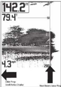
What's on the Side Imaging® Display Imaging® models only [899ci HD SI and 999ci HD SI])
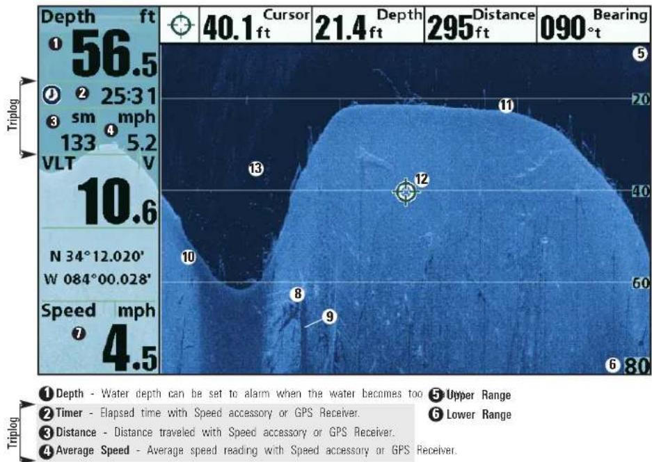
Side Imaging ^® displays a number of easily recognizable features that allow for accurate interpretation of bottom contour and structure. For Side Imaging ^® , the bottom composition determines the intensity of the sonar return. For example, rock and gravel provide a clearer sonar return than mud and sand because of their relative density. Upward slopes that face the transducer reflect sonar better than downward slopes that face away from the transducer. You can find a number of easily recognizable features on the Side Imaging ^® display that allow for accurate interpretation of bottom contour and structure, including the following items:
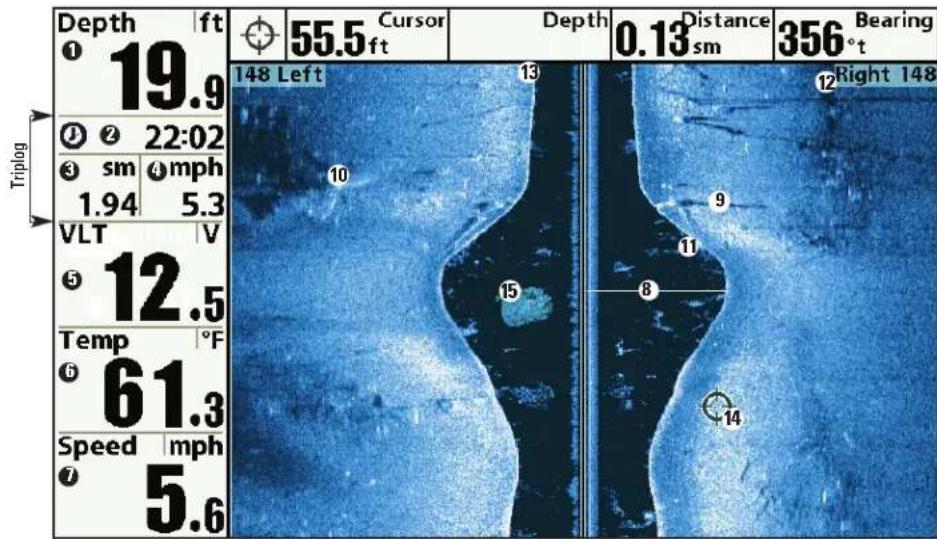
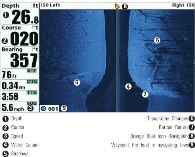
8 Water column - Shows the relative depth of the water under the boat at a given time. Variations in the width of the water column show variations in the distance to the bottom as the boat passes over.
9 Shadows - Result from a lack of reflected sonar from a particular area and can be more valuable for interpretation than the sonar reflected by the object itself. Use shadows to help you see the image in 3 dimensions, oriented in space. You can gain insight into the actual shape of an object, or the depth to which it has sunk into the bottom, through shadows on the display. Objects standing on the bottom cast a sonar shadow. The longer the shadow, the taller the object, Fish also cast shadows. You can use the shadow to interpret how close the fish is to the bottom.
Topography Changes - The light part of the screen shows where the beam is hitting hard bottom or rising terrain. The dark part of the screen indicates soft bottom (sand, mud) or descending terrain.
⑪ Bottom Return
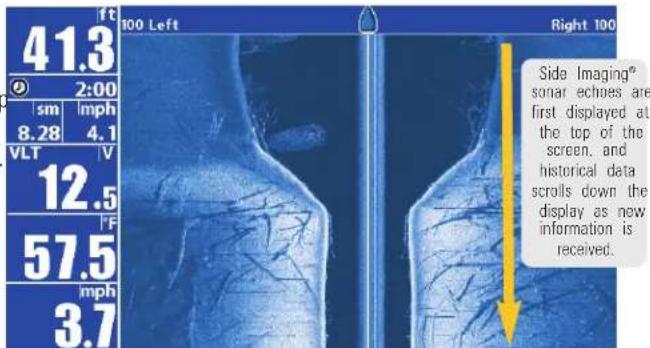
Side Imaging ^® Range - Images shown on the right side of the screen are located on the right side of your boat, and images shown on the left side of the screen are located on the left side of your boat. In this illustration, the sonar is pinging 148 feet on each side.
Top of the Display - Information from the side beams are displayed at the top of the screen. As new information is received, the historical data scrolls down the screen. For the most current information, watch the top of the screen.
14 Freeze Frame & Zoom - Use the 4-WAY Cursor Control key to move the cursor to an area on the screen, and press the ZOOM+ key to see the sonar returns in greater detail.
15 Clouded Area - May indicate a bait ball and White Streaks may indicate fish.
Understanding the Side Imaging® Display
It is important to understand how Side Imaging® technology produces the display. The images you see on the display are produced using sonar technology. The special transducer projects three distinct beams — one beam facing down and two beams pointing out to the side.
- Down Beam is aimed directly below the boat and provides conical coverage.
- Side Beams are aimed at right angles to the path of the boat. The side beam coverage is very thin from front to back, yet very wide top to bottom. The narrow aspect (front to back) of the beam illuminates a small strip of the bottom perpendicular to the direction of the boat.
Side Imaging® Representation
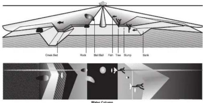
As the unit pings, a strip of data is displayed at the top of the Side Imaging ^® view.
Each time the unit pings, a strip of data representing all the echo received by the transducer are put together on the display to form the image that you see.
The rows closest to the boat icon at the top of the view are the most recent sonar data. The information is scrolled down the screen as new data, drawn at the top of the screen, becomes available.
The main benefit of Side Imaging® sonar to anglers is that it provides a overall survey of a large area of water. This gives you a better understanding of the bottom topography and how structure is oriented for more efficient fishing.
Saltwater anglers pick up precise details of popular fishing structure like wrecks, reefs, humps and drop-offs, as well as being able to spot bait in open water. Freshwater anglers can see fish-attracting structure such timber, stumps, rocks and creek beds.
SideImaging®FrequenciesandCoverage
Side Imaging® sonar uses two very precise sonar beams that are directed to either side of the boat. The beams "illuminate" the bottom contour, structure, and fish, and the results are displayed in a "picture-like" image on the screen.
- 899ci HD SI Frequencies: The side beams are operated at 455 kHz. Your Side Imaging® transducer also provides DualBeam PLUS™ at 200/83 kHz.
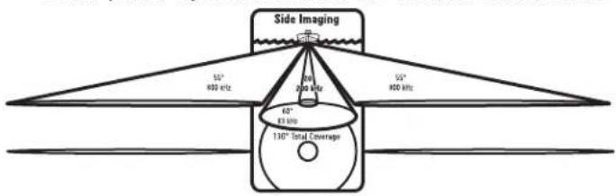
- 999ci HD SI Frequencies: The side beams can be operated at one of two frequencies: 455 kHz or 800 kHz. Your Side Imaging® transducer also provides DualBeam PLUSTM at 200/83 kHz. Selecting 800 kHz produces the sharpest image, while selecting 455 kHz provides greater bottom coverage area.
- Side Imaging® Beams are extremely narrow from front to back, and provide "thin slices" of the bottom for high resolution imaging.
- Side Imaging® Range: 240 feet to each side, with a total side coverage of 480 feet, with a depth limitation of 150 feet, depending on the contour of the bottom and when the side beam frequency selection is set to 455 kHz.
455 kHz provides maximum coverage with 180° total beam width
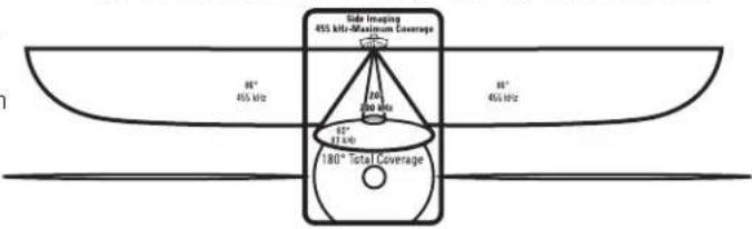
other
Side Imaging 455 MHz-Maximum Coverage | Category | Value | | :--- | :--- | | 455 MHz | 88° | | 456 MHz | 88° | | Total Coverage 456 MHz | 180° | | Total Coverage 456 MHz | 200° | The chart displays a schematic representation of an optical or radar system with labeled dimensions and coverage levels.800 kHz provides highest resolution with 130° total beam width (999ci HD SI)
For Best Performance
Use the following tips and examples to help you interpret the Side Image display.
Side Imaging® Tips
Boat speed: 2 to 6 mph
Straight line navigation
Minimum turning time and wave turbulence
Beam Coverage: When there is an area directly under the boat that do have SI beam coverage, this area will be covered by the standard 200/8 down-looking beam and displayed in the Sonar views. The net effect of on the display, is that a single object may appear as two separate entities when in reality, it is one continuous object. See Submerged Bridge: A
Perspective and the Submerged Bridge: Alternative Perspective illustrations for examples of this.
See humminbird.com for a side imaging sonar tutorial and additional information.
Boat speed: Side Imaging ^® is best performed at boat speeds between 2 to 6 mph. If the boat is stationary, the same information is displayed over and over. If the boat is moving very quickly, there will be gaps between the strips of information. The best boat speed to use will depend on the side range selected. Slower speeds are good for longer ranges, while faster speeds can be used at shorter ranges.
Boat navigation: It is important to understand that when the boat turns, successive beam strips to one side will begin to overlap and the strips on the other side will fan out, providing some distortion to the image. Because of this, the best imaging performance is produced by straight line navigation and minimal side-to-side boat motion (i.e. wave induced, etc.) This applies to navigation by either the main engine or the trolling motor. Minimize turning time and avoid wave action that induces large side-to-side rocking of the boat. For example, if there is a lot of wave activity, try to move the boat so that it is perpendicular to the waves instead of parallel with the waves in order to minimize the side-to-side rocking of the boat.
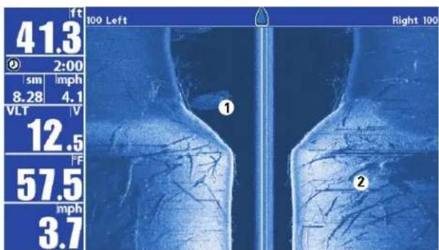
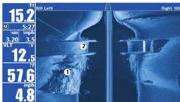
On the Water Interpretation
Submerged Bridge, Creek Channel, and New Bridge Piling
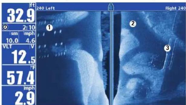
① New bridge pilings
② Creek channel
③ Submerged bridge
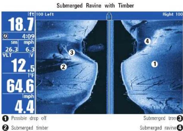
① Possible drop off
② Submerged timber
Submerged Bridge: A Closer Perspective
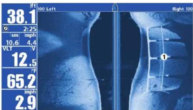
1 Submerged Bridge
Submerged Bridge, Alternative Perspective
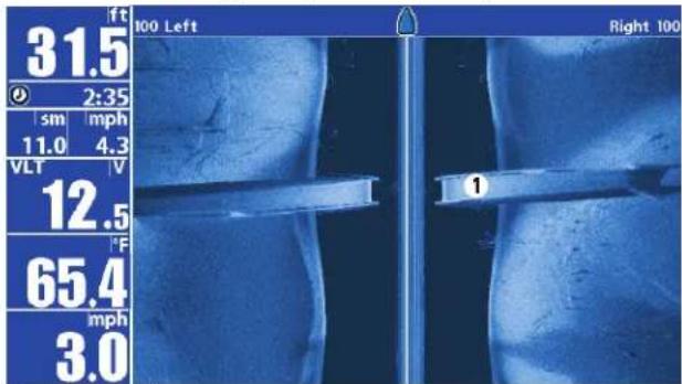
1 Submerged Bridge
Submerged Swimming Pool
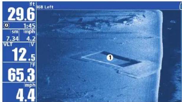
① Swimming pool
Submerged Standing and Fallen Timber, and Bait Fish
1 Bait fish
② Standing and fallen timber
Submerged Barge with Dumped Logs
1 Dumped logs
② Submerged barge
What's on the Down Imaging® Display HD DI, 959ci HD DI, 899ci HD SI, and 999ci HD SI only)
Down Imaging ^® uses unique sonar technology to provide information about the area directly below your boat. The razor-thin, high-definition profiling beams produce the detailed sonar data that you see on the display. Down Imaging ^® reveals a variety of recognizable features so that you can interpret the structure and bottom contour, including the following items:
8 Structure
7 Speed - If a GPS Receiver or Temp/Speed accessory is connected, the Fishing System can display the speed of the boat and can keep a Triplog of nautical or statute miles traveled.
9 Shadows - Result from a lack of reflected sonar from a particular area and can be as valuable for interpretation than the sonar reflected by the object itself. Use shadows to help you see the image in 3 dimensions, oriented in space. You can gain insight into the actual shape of an object, or the depth to which it has sunk into the bottom, through shadows on the display. Objects standing on the bottom cast a sonar shadow. The longer the shadow, the taller the object. Fish also cast shadows. You can use the shadow to interpret how close the fish is to the bottom.
Topography Changes - The light part of the display shows where the beam is hitting hard bottom or rising terrain. The dark part of the display indicates soft bottom (sand, mud) or descending terrain.
1 Bottom Return - Use the appearance of the bottom return to determine bottom hardness. Rock and gravel provide a clearer sonar return than mud and sand because hard objects reflect sonar better than soft objects.
⑫ Freeze Frame & Zoom - Use the 4-WAY Cursor Control key to move the cursor to an area on the screen, and press the ZOOM+ key to see the sonar returns in greater detail.
⑬ Clouded Area may indicate a bait ball and White Streaks may indicate fish.
NOTE: Entries in this view that list (with Temp/Speed or GPS Receiver) are available if either device is connected to the 800/900 Series™ Fishing System. If both devices are connected, then only the information from the GPS receiver will be displayed on the view.
Understanding the Down Imaging® Display
The images you see on the Down Imaging ^® display are produced using sonar technology. Each time the unit pings, a strip of data representing all the echoes received by the transducer are put together on the display to form the image that you see. Like traditional 2D Sonar, the sonar history scrolls left across the screen. Fre
Interpreting the Display
Down Imaging ^® beams "illuminate" the bottom contour, structure, and The beams are wide (side to side) but very thin front to back.
Use the light and dark parts of the display to interpret the objects of boat as follows:
- Dark shades represent soft returns (mud, sand) or descending terrain.
- Light shades represent denser terrain (timber, rocks) or rising terrain. A very hard bottom may appear as white on the display.
- White Streaks or Clouds may represent fish on the display.
- Shadows are not caused by light but by the lack of a sonar return. Objects standing on the bottom cause a sonar shadow to appear on the display. The longer the shadow, the taller the object. Fish may also cast shadows. You can use the shadow to interpret where the fish or object is located in relation to the bottom.
Down Imaging® Sensitivity
Use Down Sensitivity to control how the sonar returns appear on the display. Increase the sensitivity to reveal weaker returns that may be of interest, especially in very clear water or greater depths. Decrease the sensitivity to eliminate the clutter from the display that is sometimes pre in murky or muddy water. See the Down Imaging ^® X-Press ^™ Menu information.
Freeze Frame and Active Cursor
Freeze Frame and Active Cursor - Press any arrow on the 4-WAY Cursor Control key, and the screen will freeze and a cursor will be displayed. U-4-WAY Cursor Control key to move the cursor over a sonar return, and depth of the sonar return will be displayed in the cursor dialog box.
Zoom: Use the zoom keys on your control head to see the returns near cursor location at a higher magnification. See Views: Down Imaging® for more information.
Views
The sonar and navigation information from your Fishing System is displayed on the screen in a variety of easy-to-read views. Many of these views are also available as a Combo View, which shows two views on the screen at the same time.
- Default View: See below for the default view when you first power up your control head.
859ci HD: Sonar View
959ci HD: Sonar/Chart Combo View
859ci HD DI and 959ci HD DI: Chart/Down Combo View
859ci HD XD: Sonar View
959ci HD XD: Sonar/Chart Combo View
899ci HD SI and 999ci HD SI: Chart/Side Combo View
- Available Views: The available Views on your Humminbird® unit will vary with the model and the transducer attached to your control head. See Views Menu Tab and the following pages for more information
- Next View/Previous View: When you press the VIEW key repeatedly, the display cycles through the available views on your screen. When you press the EXIT key, the display cycles through the available views in reverse order.
- Customize: You can display or hide any view to suit your fishing preferences. See the following pages for more information about each View.
- Views X-Press™ Menu: Press and hold the VIEW key the 4-WAY Cursor Control key to select a view category (Sonar, Chart, Radar, Data, System) and a view. The Views X-Press™ Menu allows you to quickly access view instead of scrolling through the View Rotation.
| Sonarory |
| Chart |
| Radar |
| Data |
| System |
To customize your view rotation
You can choose which views are hidden or visible in your view rotation.
- Press the MENU key twice to access the tabbed Main Menu, then press the RIGHT Cursor key until the Views tab is selected.
- Press the UP or DOWN Cursor keys to select a View.
- Press the LEFT or RIGHT Cursor keys to change the status of the view from Hidden to Visible or vice versa.
To program each PRESET key:
Another way to access your favorite views quickly is to store them on the VIEW PRESET keys. Instead of using the VIEW key to cycle through eve view to find the one you want, you can program the VIEW PRESET key display a specific view immediately.
- Press the VIEW key to cycle to the view you want to store.
- Press and hold one of the VIEW PRESET keys for several seconds. chime will indicate that the view has been saved. You can store u to three views, one on each key.
To change the Digital Readouts:
Each view displays digital readout information (such as speed or time), which varies with the view selected, the accessory attached, and whether or not you are navigating. See Setup Menu Tab: Select Readouts for more information about which digital readout windows can be customized.
- Press the MENU key twice to access the tabbed Main Menu, then press the RIGHT Cursor key until the Setup tab is selected.
- Press the DOWN key to highlight Select Readouts, and press the RIGHT Cursor key to access the Select Readouts submenu.
NOTE: If the Select Readouts option does not appear under the Setup Tab, change the User Mode to Advanced. - Press the UP or DOWN Cursor keys to select a Readout position, then press the RIGHT or LEFT Cursor keys to choose what will be displayed in that position. To hide the data window, select Off.
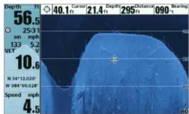
Sonar View
Sonar View presents a historical log of sonar returns. The most recent : returns are charted on the right side of the display. As new information received, the historical information scrolls left across the display.
- Upper and Lower Depth Range numbers indicate the distance from the surface of the water to a depth range sufficient to show the bottom.
- Depth is automatically selected to keep the bottom visible on the display, although you can adjust it manually as well (see Sonar X-Press™ Menu).
- Digital Readouts shown on the display will change based on the Select Readouts settings or the optional-purchase accessories attached (see Setup Menu Tab: Select Readouts).
- Freeze Frame: Use the 4-WAY Cursor Control key to freeze the display and move the cursor over a sonar return. The depth of the sonar return will be displayed at the top of the screen in the cursor dialog box.
NOTE: If the Depth number is flashing, it means that the unit is having trouble locating the bottom. This usually happens if the water is too deep, the transducer is out of the water, the boat is moving too fast, or for any other reason that the unit can't accurately receive continuous data.
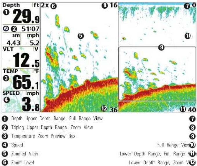
Sonar Zoom View
Sonar Zoom View provides a magnified view of the bottom and structur The Sonar Zoom View makes it easier to see separate sonar returns tha would usually be displayed close together, such as those caused by fish suspended close to the bottom or within structure.
- The Zoom Level, or magnification, is displayed in the top left corner of the display. Press the + or - ZOOM keys to increase or decrease zoom level.
- The Zoomed View is displayed on the left side of the screen. As 1 depth changes, the zoomed view updates automatically.
- The Full Range View is displayed on the right side of the screen. Full Range View includes the Zoom Preview Box, which shows when the zoomed view is in relation to the full range view.
- The Upper and Lower Depth Range numbers indicate the high and low range of the water which is being viewed.
- Digital Readouts shown on the display will change based on the Select Readouts settings or the optional-purchase accessories attached (see Setup Menu Tab: Select Readouts).
Freeze Frame: Use the 4-WAY Cursor Control key to freeze the display and move the cursor over a sonar return. The depth of the sonar return will be displayed at the top of the screen in the cursor dialog box.
Sonar Zoom View
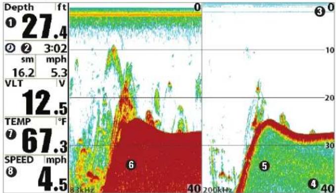
Split Sonar View
Split Sonar View displays sonar returns from each down beam frequency separate sides of the screen. You can use the Split Sonar View to make by side comparisons between the sonar returns from both beams.
- DualBeam PLUS™ models (859ci HD, 959ci HD, 899ci HD SI, 999ci HD SI) display sonar returns from the 83 kHz wide beam on left side of the screen and sonar returns from the 200 kHz narrow beam on the right side of the screen.
- Down Imaging® models (859ci HD DI, 959ci HD DI) display traditional 2D sonar returns from the 455 kHz narrow beam on the left side of the screen and sonar returns from the 200 kHz wide beam on the right side of the screen.
- Xtreme Depth models (859ci HD XD, 959ci HD XD) display sonar returns from the 50 kHz wide beam on the left side of the screen. Sonar returns from the 200 kHz narrow beam on the right side of a screen.
- Depth is displayed in the upper left hand corner.
- The Digital Readouts in the Split Sonar View cannot be customized therefore, information such as water temperature and voltage are unavailable in the Split Sonar View.
- Freeze Frame: Use the 4-WAY Cursor Control key to freeze the display and move the cursor over a sonar return. The depth of the sonar return will be displayed at the top of the screen in the cursor dialog box.
Split Sonar View (859ci HD, 959ci HD, 899ci HD SI, and 999ci HD SI)
line
| Metric | Value | |--------|-------| | Depth (ft) | 27.4 | | Velocity (mph) | 16.2 | | VLT (V) | 12.5 | | Temp (°F) | 67.3 | | Speed (mph) | 4.5 | | Time (kHz) | 8.3, 40, 200kHz | | Depth (nm) | 0 | | Velocity (mph) | 10 | | VLT (V) | 20 | | Temp (°F) | 30 | | Speed (mph) | 40 | | Time (kHz) | 200kHz |1 Depth
② Triplog
③ Upper Depth Range
4 Lower Depth Range
200 kHz Sonar History Windo 5
83 kHz Sonar History Windo 6
Temperature 7
Speed 8
Side Imaging® View 899ci HD SI and 999ci HD SI only)
Side Imaging® View shows a shadowed right- and left-looking view from boat as the boat passes over the bottom. See Understanding the Side Imaging® Display for more information about interpreting the Side Imag View.
- Side Imaging® X-Press™ Menu: Press the MENU key once to access the Side Imaging® X-Press™ Menu. You can choose a side of the water to view, the sensitivity of the sonar to see more or less detail, the side beam range, the chart scrolling speed, and the display color scheme. See Side Imaging® X-Press™ Menu, as well Understanding the Side Imaging® Display for more information.
-
Freeze Frame: Press any arrow on the 4-WAY Cursor Control key, a the SI View will freeze and a cursor will appear on the screen. Use the 4-WAY Cursor Control key to move the cursor over a sonar retu and observe the following:
-
The depth of the sonar return you choose will be displayed in the cursor information box.
- Zoom+: Press the ZOOM+ key, and a zoom box will appear an magnify the area you choose, providing more detail in the individual sonar returns. The zoom scale will increase or decrease as you press + or - repeatedly. Press EXIT to remove the zoom box and return to Side Imaging® View.
- Navigation: You can mark waypoints (press the MARK key), start navigation to a specified waypoint, or navigate to the cursor location. See Introduction to Navigation: Navigate to a Waypoint or F for more information.
- Navigation readouts will display at the bottom of the screen when navigation starts.
- Boat Icon: When you start navigation, the boat icon at the top of the screen will indicate the direction the boat needs to turn to reach the waypoint. The boat icon color will also change to orange. See Navigation Menu Tab: SI Navigation and Introduction to Navigation for more information.
Side Imaging® View (while Navigating)
Side Imaging ^® View, with Active Cursor and Zoom
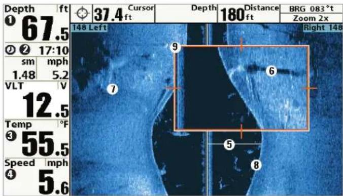
① Depth Water Column ⑤
② Triplog Shadows ⑥
③ Water Surface Temperature Topography Changes ⑦
4 Speed Bottom Return 8
Zoom Box9
Down Imaging® View
(859ci HD DI, 959ci HD DI, 899ci HD SI, and 999ci HD SI only)
Down Imaging® models (859ci HD DI, 959ci HD DI) use the razor-thin, high-definition profiling beams to produce the detailed sonar data that you see on the display.
Side Imaging ^® models (899ci HD SI, 999ci HD SI) display the down beam portion of the data from the Side Imaging ^® beams. The Down Imaging ^® results are displayed in a "picture-like" image on the screen in 2D format
Sonar returns are charted on the right side of the display. As new information is received, the historical information scrolls left across the display. See What's on the Down Imaging® Display for more informa
- Coverage: The Down Imaging® coverage is always very thin front to back, and the side to side width can be adjusted (see Sonar Menu Tab: Down Imaging® Beam Width).
- Down Imaging® X-Press™ Menu: Press the MENU key once to accept the Down Imaging® X-Press™ Menu. You can set the sensitivity of the sonar to see more or less detail, the chart scrolling speed, and the display color palette (see Down Imaging® X-Press™ Menu).
- Freeze Frame: Press any arrow on the 4-WAY Cursor Control key, and the Down Imaging® View will freeze and a cursor will appear on the screen. Move the cursor over a sonar return, and observe the followi
- The depth of the sonar return you choose will be displayed in the cursor information box.
- Zoom+: Press the ZOOM+ key, and a zoom box will appear an magnify the area you choose, providing more detail in the individual sonar returns. The zoom scale will increase or decrease as you press + or - repeatedly. Press EXIT to remove the zoom box and return to Down Imaging® View.
Down Imaging® View
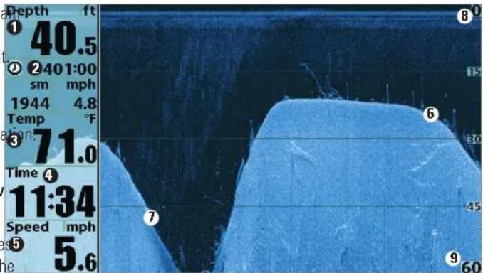
① Depth Bottom Return
② Triplug
③ Water Surface Temperature
4 Time
5 Speed
6
Topography Changes⑦
Upper Ran8
Lower Range⑨
Down Imaging® View, with Active Cursor and Zoom
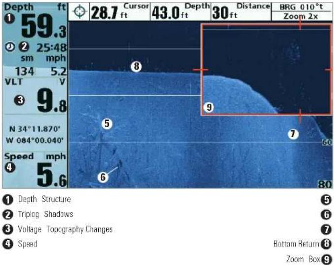
Snapshot and Recording View
(optional-purchase SD Memory card required)
Snapshot and Recording View displays the screen snapshots and recordings that are saved on the optional-purchase SD card installed in the control head. Use this view to review the snapshot and recording file data start recording, and adjust the recording settings.
- Activate Screen Snapshot: Select Screen Snapshot from the Accessories Menu Tab, and select On. Also, install an optional-purchase SD memory card in the control head, and make sure Snapshot and Recording View is set to Visible on the Views Menu Tab.
- Scroll and View: Use the UP and DOWN Cursor keys to scroll through the saved Screen Snapshots and Recordings. The active file is highlighted with arrows. Press the RIGHT Cursor key to view the file.
- Snapshot and Recording X-Press™ Menu: Press the MENU key once in this view to open the X-Press™ Menu. Use the X-Press™ Menu to Start Recording, Delete Images, or adjust the Recording and Playback settings (see Recording and Playback or Snapshot and Recording X-Press™ Menu).
NOTE: The speed of the screen capture or the recording depends on the t, of card you use; in general, SD cards capture the screen faster than MMC cards.
Snapshot and Recording View
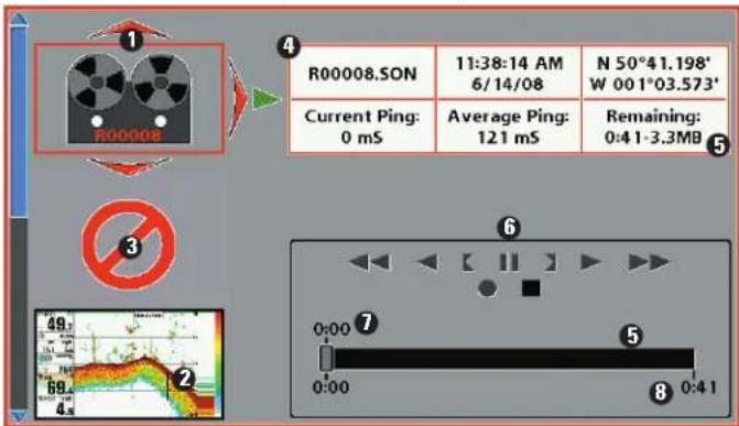
1 Recording icon
Amount of recording left to p5
② Snapshot thumbnail
Recording mode icons 6
③ Unavailable icon
Amount of recording that has been pla7
4 Information box
Amount of space used for this record 8
NOTE: For snapshots and recordings, the indicator bar has several states: during recording, the amount of space remaining on the SD card is indicated on the status bar. During playback, the amount of time/memory remaining to play is indicated on the status bar. When a snapshot thumbnail is highlighted, the amount of room remaining on the SD card is indicated.
Screen Snapshots
Screen Snapshots are saved pictures of the view on the screen. The sc snapshot will include the menus, dialog boxes, warnings, and messages were active when the screen snapshot was taken. Saved Screen Snapshot can be viewed from the Snapshot and Recording View or Chart View.
The Screen Snapshot feature is available when an optional-purchase SD memory card is installed and Screen Snapshot is On (see Accessories M Tab: Screen Snapshot).
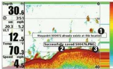
heatmap
| Point | Value | |---|---| | 1 | 30.6 | | 2 | 3:51 | | 3 | 20.3 | | 4 | 5.2 | | 5 | 20.3 | | 6 | 12.5 | | 7 | 70.3 | | 8 | 4.5 | Waypoint S00472 already exists at this location Successfully saved S00476.PNG① Waypoint saved at Cursor Location
② Screen Snapshot Confirmation
3 File Name
Make a Screen Snapshot:
-
Activate Screen Snapshot and install an SD card.
-
From any view or cursor location you want to capture, press the MARK key. The screen will pause while the image is saved.
A waypoint will also be created at the boat or active cursor location. TI screen snapshot shares the same file name (.PNG).

① From Snapshot and Recording View, select Delete Image from the X-Press™ Menu.
Delete a Screen Snapshot:
- From the Snapshot and Recording View, press the UP or DOWN Cursor keys to scroll through the saved files and highlight a snapshot file.
- Press the Menu key once, and select Delete Image from the X-Press™ Menu.
- Press the RIGHT Cursor key.
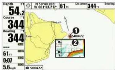
① Screen Snapshot Icon and Waypoint Name
② Thumbnail Preview
(press the INFO key to view at full size)
View a saved Screen Snapshot from Chart View:
- In Chart View, use the 4-WAY Cursor Control key to move the active cursor onto a Screen Snapshot Icon
When the cursor snaps onto the Screen Snapshot Icon, a thumbnail preview of the Screen Snapshot will be displayed on the screen.
NOTE: Navigation is not affected by the Screen Snapshot feature. Also, if Screen2. Press the INFO key, and select View Snapshot. Snapshot is enabled, but a GPS receiver is not connected, pressing the MARK key will capture the screen image but an error will display that says a GPS position 3. Press the EXIT key to return to Chart View.
fix is required to create a waypoint.
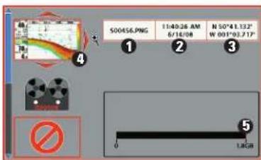
① Snapshot File Name
② Time + Date of Snapshot
③ Waypoint Position
4 Highlighted Snapshot File
⑤ SD card available storage
View a saved Screen Snapshot from Snapshot and Recording View:
- From the Snapshot and Recording View, press the UP or DOWN Cursor keys to scroll through the saved files and highlight a snapshot file.
- Press the RIGHT Cursor key.
en2. Press the INFO key, and select View Snapshot.
n 3. Press the EXIT key to return to Chart View.
Notes about Screen Snapshots:
- A border around the full screen indicates that the view is a saved screen snapshot and not a "live" view.
- If you press the INFO key, and the snapshot file connected to the icon is not saved on the installed SD card, the Chart Information b will display instead of the screen snapshot.
- Use an optional-purchase SD card reader connected to a PC to view the saved screen snapshot data files on your optional-purchase SD card (see humminbird.com for details). You will notice that a .DAT a .TXT) file is created for every .PNG screen snapshot. This data file required for viewing the screen snapshots from your control head, so don't delete these files.
Recording and Playback
The Recording feature records active sonar information. When the recording• While recording, press the EXIT key to exit the Snapshot and is played back, the views that were active during the recording are availableRecording X-Press™ Menu and scroll to a different view. Recording in Playback. The Recording and Playback feature is available when an will continue.
optional-purchase SD card is installed and Screen Snapshot is On (see Accessories Menu Tab: Screen Snapshot). Saved Recordings can be played shows the recording progress and remaining space on the SD card.
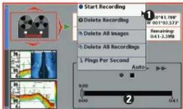
① From Snapshot and Recording View, select Start Recording from the X-Press™ Menu
② Slider Bar
Start recording:
-
From the Snapshot and Recording View, press the MENU key once to open the Snapshot and Recording X-Press™ Menu.
-
Highlight Start Recording, and press the RIGHT Cursor key. A waypoint will also be created at the boat location, and the recording shares the same file name (.SON).
Notes about Recording
ling• While recording, press the EXIT key to exit the Snapshot and ilableRecording X-Press™ Menu and scroll to a different view. Recording will continue.
- The slider bar at the bottom of the Snapshot and Recording View layed shows the recording progress and remaining space on the SD card.
- Pings Per Second: For maximum performance, keep the Pings Per Second setting on Auto (see Snapshot and Recording X-Press™ Menu).
- Viewing saved Screen Snapshots and Recording Playback are not available while in recording mode.
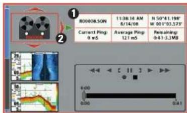
① Recording File Information
② Highlighted Recording File
Playback a Recording:
-
From the Snapshot and Recording View, press the UP or DOWN Cursor keys to scroll through the saved files and highlight a saved Recording.
-
Press the RIGHT Cursor key.
Stop recording
- In any view, press the MENU key once to open the Snapshot and Recording X-Press™ Menu.
- Highlight Stop Recording and press the RIGHT Cursor key.
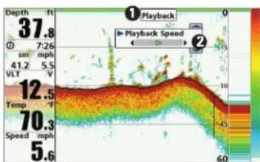
heatmap
| Depth (ft) | 37.8 | |---|---| | 0 | 7:26 | | 1 | 41.2 | | 2 | 5.5 | | 3 | V | | 4 | 12.5 | | 5 | 70.3 | | 6 | 5.6 | Playback Speed: 15-60 Playback Speed: 15-60① "Playback" indicates the control head is playing a saved recording.
② Open the X-Press™ Menu to adjust
Playback settings.
You can also use Freeze Frame and mark waypoints.
Stop Playback
- Press the MENU key once to open the Snapshot and Recording X-Press™ Menu.
- Highlight Stop Playback, and press the RIGHT Cursor key.
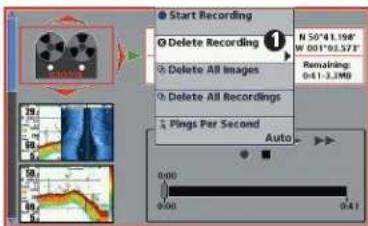
① From Snapshot and Recording View, select Delete Recording from the X-Press™ Menu.
Change Playback Settings:
- Press the MENU key once to open the Snapshot and Recording X-Press™ Menu.
- Use the X-Press™ Menu to adjust the Sonar Recording's Sensitivity, Upper Range, Lower Range, and the Playback Speed. See
Snapshot and Recording X-Press™ Menu for details.
Delete a Recording:
- From the Snapshot and Recording View, press the UP or DOWN Cursor keys to scroll through the saved files and highlight a saved Recording.
- Press the Menu key once, and select Delete Recording from the X-Press™ Menu. Press the RIGHT Cursor key.
Notes about Playback:
- "Playback" will flash periodically on the screen to indicate that the control head is playing a saved recording and not a "live" view.
- Navigation is not affected by the Sonar Recording feature, but any active navigation is cancelled and thumbnails and icons disappear when Playback begins or ends.
- Playback is paused automatically at the end of the recording.
- Freeze Frame: Press the 4-WAY Cursor Control key to pause Playba and move the Active Cursor to a location on the sonar view. The Cursor dialog box will show the depth and information for the location you choose. Press Exit to resume Playback.
- Press the MARK key during Playback to save a Screen Snapshot and/or mark a waypoint in the view or active cursor location you choose.
Recording Information
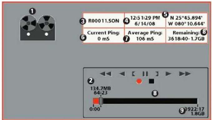
① Recording Indicator
Current Ping Rate 6
② Amount of space and time used by this recording
Average Ping Rate 7
③ Name of recording
Amount of space remaining on c8
④ Time and Date recording was started
Total amount of space on c9
⑤ Position where recording was started
NOTE: Sonar chart speed is increased during Fast Forward and reversed during Rewind. This may reduce the quality of the sonar image, since at higher speeds, not every sonar return can be processed and displayed.
Side Beam View
(with optional-purchase QuadraBeam PLUS™ transducer)
Side Beam View displays sonar data from the left and right 455 kHz by and the 200 kHz down-looking beam in one view. This view is available optional-purchase QuadraBeam PLUS™ transducer accessory is connected and Connected Transducer is set to QuadraBeam (see Sonar Menu Tab Connected Transducer).
NOTE: The QuadraBeam PLUS™ transducer requires a separate purchase.
- Bottom View: The sonar information from the side-looking beams reveals bottom contour, structure, and fish similar to the down-looking beam, but the area covered is to the left and right, which gives you a wider view of the bottom.
- Distance: The distance covered by the right and left side-looking beams is controlled by the Lower Range setting for the down-looking beam, up to a maximum of 160 feet (see Sonar X-Press™ Menu: Lower Range).
- Settings: The Side Beam View can be arranged in any of the following layouts: Default, Classic, and Slanted. To select a layout, press the MENU key once to access the Sonar X-Press™ Menu. Scr down using the DOWN Cursor key until Quad Layout is highlighted. Then press the LEFT or RIGHT Cursor keys to select a layout setting
Default layout: The top portion of the display presents a historical log of Classic layout: The top portion of the display presents a historical log of sonar returns from the 200 kHz down-looking sonar beam. New information onar returns from the 200 kHz down-looking sonar beam. New information in the down beam panel scrolls from right to left. The bottom portion of the down beam panel scrolls from right to left. The bottom portion of display presents a historical log of sonar returns from the 455 kHz right-diaphy presents a historical log of sonar returns from the 455 kHz right-left-looking sonar beams. New information in the side beam panels scroll left-looking sonar beams. New information appears at the top and scrolls from the center out. down the display.
Side Beam View, Default Layout
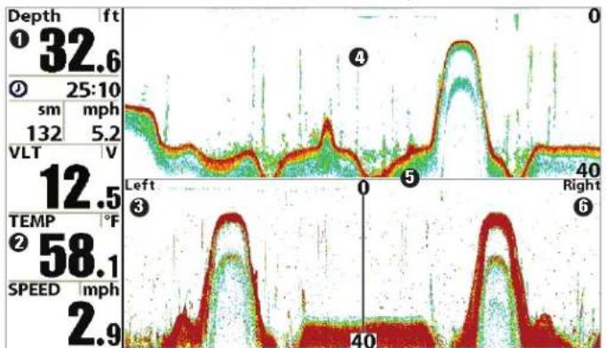
line
| Depth | Value | |-------|-------| | 32.6 | | | 12.5 | | | 58.1 | | | 2.9 | |1 Depth
200 kHz Sonar History Windo 4
② Temperature
Water Surface Line for 455 kHz Sonar History Win £ vs
3 Left Side 455 kHz Sonar History Window
Right Side 455 kHz Sonar History Wind6
Side Beam View, Classic Layout
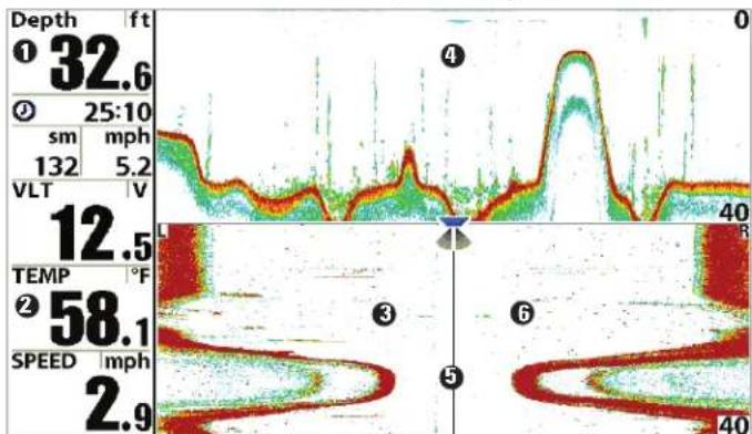
1 Depth
200 kHz Sonar History Windo 4
② Temperature
Water Surface Line for 455 kHz Sonar History Windows
3 Left Side 455 kHz Sonar History Window
Right Side 455 kHz Sonar History Wind ^6
Slanted layout: This layout is presented as three slanted panels representing the two 455 kHz side sonar beams and the 200 kHz down-looking sonar beam. New information appears on the right and scrolls to left.
Side Beam View, Slanted Layout
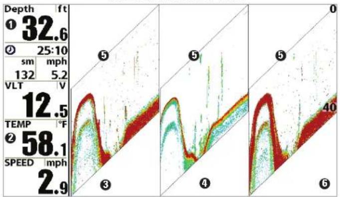
area
| Panel | Depth (ft) | Velocity (V) | Temperature (°F) | Speed (mph) | |-------|------------|--------------|------------------|-------------| | 0 | 32.6 | 12.5 | 58.1 | 2.9 | | 1 | 25:10 | 132 | | | | 2 | | | | | | 3 | | | | | | 4 | | | | | | 5 | | | | | | 6 | | | | |1 Depth 200 kHz Sonar History Windo 4
② Temperature Water Surface Line for 455 kHz Sonar History Windows
3 Left Side 455 kHz Sonar History Window Right Side 455 kHz Sonar History Wind
Bird's Eye View
Bird's Eye View shows a 3D perspective view of the track and the cha land contour from a point above and behind the boat (the eye point). A boat turns, the eye point moves to follow the boat.
- To shift the eye point position so that you can look off to the sides, or even behind the boat: Press the RIGHT or LEFT Cursor keys to the eye point right or left. Press the UP Cursor key to move the eye point forward, and press the DOWN Cursor key to move the eye point backward.
- Press the EXIT key to move the eye point back to its original pos behind and above the boat.
Bird's Eye View
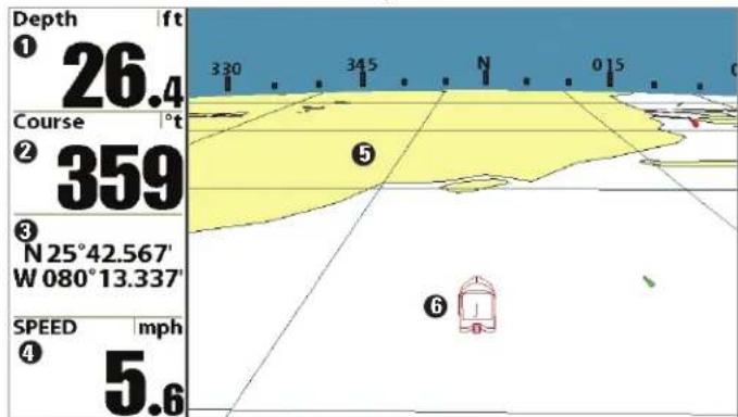
① Depth Speed of Boat 4
② Course: Direction the boat is traveling relative to North Reference Land Contours 5
③ Latitude and Longitude Position of Boat Boat Icon 6
Chart View
Chart View shows cartography from the built-in Contour XD™, built-in UniMap™, or an optional SD map for the area surrounding your current position. The cartography is applied to any standard Chart View or Combo View that displays a chart. The current track (also known as the position history or breadcrumb trail) showing where the boat has been, along with saved tracks, waypoints, and the current route (when navigating), are overlaid on the chart.
- Shift/Pan: Use the 4-WAY Cursor Control key to shift/pan the chart to another area.
- Zoom: Press the ZOOM (+/-) keys to zoom in and out.
• Information: Press the INFO key to get information about the chart objects near the cursor.
Chart View with Active Cursor
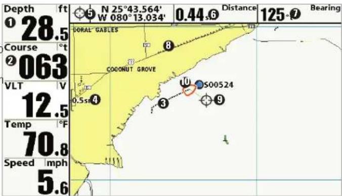
① Depth Distance to the Cursor
② Course: Direction the boat is traveling relative to North Reference.
3 Track (Breadcrumbs Trail)
4 Map Scale
⑤ Latitude and Longitude Position of Cursor
6
Bearing to Cursor 7
Cartography 8
Active Cursor 9
Boat Icon 10
Combo Views
Side Imaging®/Sonar Combo View (899ci HD SI and 999ci HD SI only)
Combo Views display two views (or more) on the screen at the same time. You can perform functions for either side of the view, access the X-Press Menu, and change the left view display size. The available combo views are on the left and the Side Imaging® View is displayed on the right.
shown on the following pages.
Combo Views: Functions
The Combo Views allow you to view and control two views at once. To change the settings in a View, the view must be selected as the active side.
- The green arrow points to the active side.
- Active Side: Press the MENU key once and select Active Side from the X-Press™ Menu. Choose RIGHT or LEFT to set the active side.
- X-Press™ Menu: After you set the Active Side, press the MENU key once to access the X-Press™ Menu. The X-Press™ Menu provides settings for the active view, and the display updates immediately with your changes.
- Display Size: Press the MENU key once and select Split Position from the X-Press™ Menu. Split Position allows you to adjust the size of the left side of the display.
• Active Cursor: Press any arrow on the 4-WAY Cursor Control key, the cursor will appear on the active side of the view.
Select an Active Side, and you can adjust the sensitivity, the side beam range, the chart scrolling speed, and the color scheme of the display. For more information about each side of this combo view, see Sonar View and
Side Imaging® View.
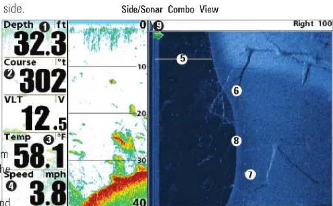
① Depth Shadows
② Course: Bearing of Boat with Respect to North Reference
③ Water Surface Temperature Bottom Return
4 Speed Green Arrow: Active Side
5 Water Column
6
Topography Changes 7
8
9
Chart/Bird's Eye Combo View
Chart/Chart Combo View
Chart/Bird's Eye Combo View shows the Chart and Bird's Eye views in Chart/Chart Combo View shows two versions of the Chart view in a combination split screen, where the Bird's Eye View is displayed on the defubination split screen so that you can see the position of the boat o and the Chart View is displayed on the right. For more information about side while you zoom in or perform other functions on the other. See CI each side of this combo view, see Chart View and Bird's Eye View.View for more information.
Chart/Bird's Eye Combo View with Active Cursor
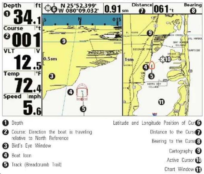
Chart/Chart Combo View with Active Cursor
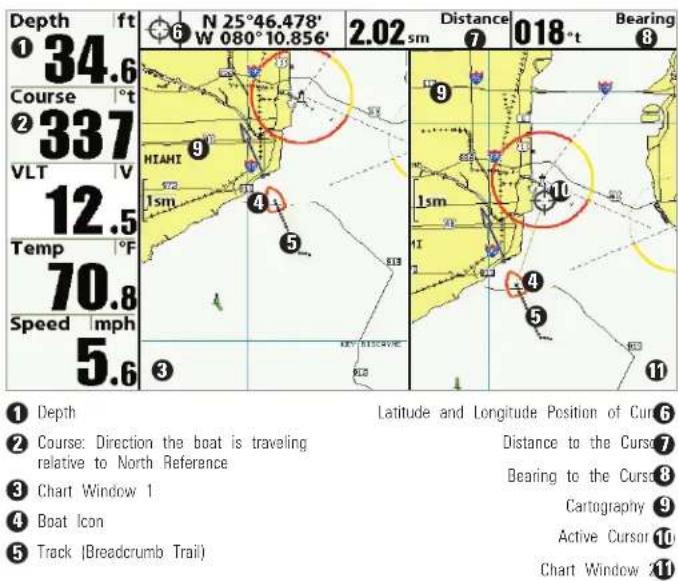
Chart/Sonar Combo View
Chart/Sonar Combo View shows both the Chart and Sonar views in a combination split screen, where the Sonar View is displayed on the left the Chart View is displayed on the right. For more information about ea side of this combo view, see Chart View and Sonar View.
Chart/Sonar Combo View
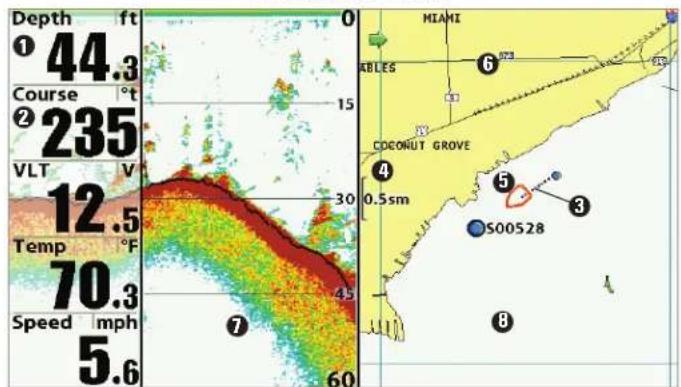
① Depth
② Course: Direction the boat is traveling relative to North Reference
③ Track (Breadcrumbs Trail)
4 Map Scale
Boat Icon 5
Cartography 6
Sonar Window⑦
Chart Window 8
Chart/Side Imaging® Combo View (899ci HD SI and 999ci HD SI only)
Chart/Side Imaging® Combo View shows chart information and Side Imaging® sonar information in a combination split screen, where the Side Imaging® View is displayed on the left and the Chart View is displayed right. For more information about each side of this combo view, see Ch. View and Side Imaging® View.
Chart/Side Combo View
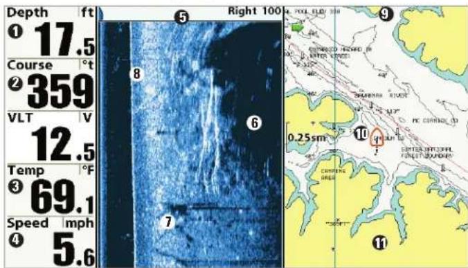
① Depth Topography Changes
② Course: Bearing of Boat with Respect to North Reference
③ Water Surface Temperature Chart View Window
4 Speed of Boat Boat Icon
⑤ Side Imaging® View Window Cartography
6 Shadows
7
Bottom Return 8
9
10
11
Down Imaging®/Side Imaging® Combo View
(899ci HD SI and 999ci HD SI only)
Down/Side Imaging® Combo View shows Down Imaging® and Side Imaging® sonar information in a combination split screen, where the Imaging® View is displayed on the left and the Side Imaging® View displayed on the right. For more information about each side of this view, see Down Imaging® View and Side Imaging® View.
Down Imaging®/Side Imaging® Combo View
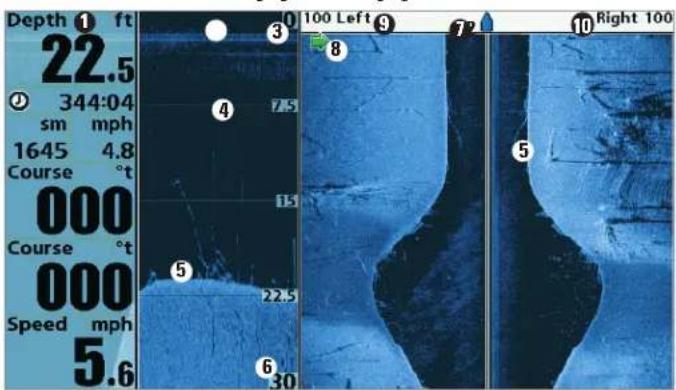
1 Digital Readouts
② Down Imaging® View Window
③ Upper Depth Range
4 Depth Lines
5 Bottom Return
Lower Depth Range6
Side Imaging® View Window⑦
Green Arrow: Active Sid 8
Side Imaging ^* Range (Lef 9)
Side Imaging® Range (Right 10)
Chart/Down Imaging® Combo View
(859ci HD DI, 959ci HD DI, 899ci HD SI, and 999ci HD SI only)
Chart/Down Imaging® Combo View shows Chart and Down Imaging® Downinformation in a combination split screen, where the Down Imaging® View is displayed on the left and the Chart View is displayed on the right. For coninformation about each side of this combo view, see Down Imaging® I and Chart View.
Chart/Down Imaging® Combo View
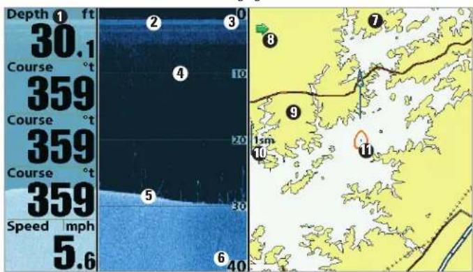
① Digital Readouts Chart View Window
② Down Imaging® View Window
③ Upper Depth Range Cartography
4 Depth Lines Map Scale
⑤ Bottom Return Boat Icon
6 Lower Depth Range
7
Green Arrow: Active Sid 8
9
10
11
Down Imaging®/Sonar Combo View
(859ci HD DI, 959ci HD DI, 899ci HD SI, and 999ci HD SI only)
Down Imaging®/Sonar Combo View shows traditional Sonar information the left and Down Imaging® sonar information on the right. For more information about each side of this combo view, see Down Imaging® and Sonar View.
Down Imaging®/Sonar Combo View
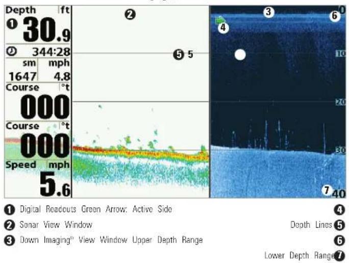
Down Imaging®/Side Imaging®/Sonar Combo View
(899ci HD SI and 999ci HD SI only)
Down/Side Imaging®/Sonar Combo View shows Down Imaging® and traditional Sonar information on the left side of the screen, and Side Viewing® on the right side of the screen. If you use the active cursor of left side of the screen, a cursor will appear in both the Sonar and Dow Imaging® views. For more information about each side of this combo view see Down Imaging® View, Side Imaging® View, and Sonar View.
Down Imaging®/Side Imaging®/Sonar Combo View
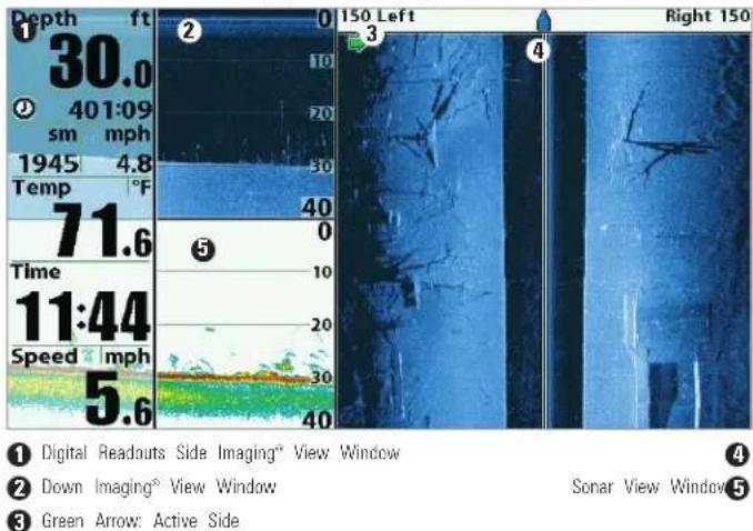
View Orientation
Both Chart and Chart Combo Views allow you to choose the orientation, the view (see Navigation Menu Tab: Chart Orientation). In each orientation, the view pans automatically so that the boat is always centered on the display. To see more of the view when the boat is traveling at the spe set, see Chart Menu Tab: Vessel Offset and Offset Speed.
- North-Up: True North is shown at the top of the display. Objects located to the north of the boat are drawn above the boat.
- Heading-Up: The boat's current heading points up, and the chart rotates around the vessel so that the vessel always points up on view.
- Course-Up: During navigation, the projected course is shown at the top of the view. Objects ahead of the boat are drawn above the boat. The boat is not navigating, the course-up reference is provided by the COG (course over ground) calculation. Also, to display the north icon the view, see Navigation Menu Tab: North-Up Indicator.
North-Up Icon: If it is turned on, the North-Up Icon displays the direction True North. It also displays the Chart Orientation, and the icon will change as the orientation and the data source change (see Navigation Menu Ta North-Up Indicator).

When the boat is stationary, it is drawn as a circle.

When the boat is in motion, it takes on a boat shape, pointed in the direction of motion (always up in the Course-Up orientation).
Viewing Cartography
In the Chart and Chart Combo Views, there are several cartography-related functions that you can access using various keys.
eBanning: Use the 4-WAY Cursor Control key to move the chart around a display in the direction of the key being pressed. When you do this, a eye cursor is drawn at the center of the screen and is linked to the body a gray line, even if the boat is off the screen. At the same time, a curved dialog box is displayed at the top of the screen with the distance and from the boat to the cursor position and the latitude/longitude coordinate of the cursor. When the cursor is active on the display, you can also use 4-WAY Cursor Control key to move the cursor diagonally.
Chart View with Cursor Present
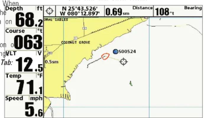
Zooming: Press the Plus (+) key to Zoom In and the Minus (-) key to Out to see the cartography at different magnification levels. The zoom le is indicated on the left side of the display. If you zoom in beyond the chart data, the display will go into Overzoom mode whereby the last available chart data is amplified to reflect the level selected. If you zoom so far that no cartography is available, a lat/long grid will be drawn in: Zooming is also influenced by the Auto Zoom and Auto Range settings. Chart Menu Tab: Auto Zoom and Auto Range for more information
Decluttered Waypoints: When two or more waypoints overlap, or are displayed close together on a chart view, the screen will automatically declutter — waypoint names will shorten and the waypoint icons will change into small blue icons.
To view a Decluttered Waypoint at full size, use the 4-WAY Cursor Co key to move the cursor onto a decluttered waypoint icon. When the c snaps onto the icon, the full-size waypoint name and icon will be disp You can also press the + ZOOM key until you can see the individual waypoints on the screen.
Screen Snapshots and Recording Icons: When a waypoint is created Screen Snapshot and Recording is active, the waypoint will appear as snapshot icon or recording icon in chart views. See Views: Snapshot Recording View for more information.
Chart Info: Press the INFO key to get detailed information about the cursor. If the cursor is active, you will see information about the chart object located near the cursor.
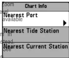
If the cursor is not active, the Chart Info submenu will appear. Use the 4-WAY Cursor Control key to select the Nearest Port, the Nearest Tide Station, or the Nearest Current Station and see information about any of these objects.
NOTE: The built-in UniMap™ does not contain any Port, Tide, or Current information. This information is only available from optional-purchase SD cards.
Nearest Port: The position and services information for the nearest port your present position will be displayed. Press the EXIT key to remove the information box and the cursor bull's eye will be centered over the port position. The cursor information boxes will indicate the distance and bear to the port from your present position.
Nearest Tide Station: Tide information for the nearest tide station to you present position will be displayed. This includes the position of the station and the times of the high and low tides for today's date. A tide graph displayed showing the rise and fall of the tides for the 24 hour time point encompassing the date. You can change the date to look at tide information before or after the date displayed by pressing the LEFT or RIGHT Cursor respectively. Press the EXIT key to remove the information box, and the
nattorsor bull's eye will be centered over the tide station position. The cur- sinformation boxes indicate the distance and bearing to the tide station fi your present position.
Nearest Current Station: Current information for the nearest current station Waypoints, Routes, and Tracks
to your present position will be displayed. This includes the position of the station and the current changes for today. Two graphs are also presented that show the time, direction, and flow speed of the current changes for 24 hour time period of today's date. You can change the date to look at current information before or after the date displayed by pressing the LEFT or RIGHT Cursor key respectively. Press the EXIT key to remove the information box, and the cursor bull's eye will be centered over the current station position. The cursor information boxes will indicate the distance and bearing to the current station from your present position.
Introduction to Navigation
Your Fishing System allows you to mark waypoints and start navigation w the control head keys or the Navigation X-Press™ Menu.
You can also use the Waypoint Management dialog box to create new waypoints and routes from scratch. You can edit your navigation data and organize it too. This section will get you started. See your Humminbird® Waypoint Management Guide for complete details.
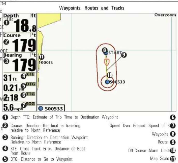
scatter
| Point | Destination | Distance (ft) | |-------|-------------|---------------| | 1 | S00533 | 1000 | | 2 | DTG | 179 | | 3 | XTE | 31 | | 4 | DTG | 0.21 | | 5 | DTG | 2.18 | | 6 | DTG | 5.6 | | 7 | SOG | 5.6 | | 8 | START | 1 | | 9 | S00533 | 1000 |Waypoints are stored positions that allow you to mark areas of interest navigation points. Your Fishing System can store up to 2,750 waypoints.
Routes link two or more waypoints together to create a path for naviga are used in trip planning. You can link individual waypoints together by the GOTO key. Your Fishing System can store up to 45 routes that can contain up to 50 waypoints.
A route represents your intended navigation and shows the shortest path each waypoint to the next. As you travel a route, staying on the route most efficient way to get to your destination, although you should always out for obstacles not shown on the chart. A Route Leg is the path between each waypoint in a route. The color of each route leg is displayed as f
• Completed Route Leg = Gray.
- Current Route Leg = Green.
• Future Route Leg = Gold.
Tracks consist of detailed position history and are displayed as a breadcrumb trail of trackpoints. The Current Track shows the position his since the unit was powered up. You can clear the Current Track or save any time. Your Fishing System can store up to 50 saved tracks, each containing 20,000 trackpoints. The current track represents your actual pa so far.
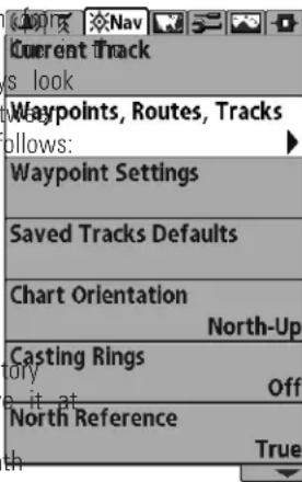
Opening the Waypoint Management Dialog Box
NOTE: The maximum number of waypoints and routes may vary due to the setup of your Waypoint Management directory. Groups and sub-groups also use storage, and the storage limit is influenced by the complexity of your Waypoint Management directory.
Open the Waypoint Management Dialog Box
The Waypoint Management dialog box allows you to organize your waypoints, routes, and tracks on your Humminbird® control head.
Open the Waypoint Management Dialog Bo
- Press the MENU key twice to open the Main Menu.
- Press the RIGHT Cursor key until the Navigation Menu Tab is selected.
- Press the DOWN Cursor key to choose Waypoints, Routes, Tracks. Press the RIGHT Cursor key to open the Waypoint Management dialog box.
What's on the Waypoint Management Dialog Box
Use the Waypoint Management dialog box to manage your waypoints, routes, and tracks.
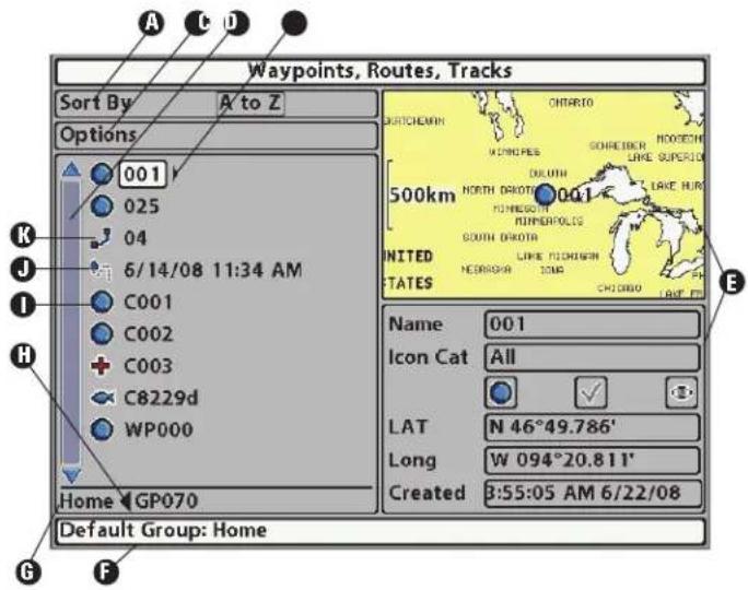
Use the 4-WAY Cursor Control key to select a waypoint, route, track, group, or menu option. To scroll through the list, press the UP or DOWN Cursor keys. To open a submenu, press the RIGHT Cursor key. To move to the higher level group, or the higher level directory, press the LEFT Cursor key.

As you scroll through the Waypoint Management dialog box, press the EXIT key to select the Options menu quickly. Press the EXIT key twice to close the dialog box.
A Sort By: Select Sort By, and press the RIGHT Cursor key repeatedly to choose a sorting option for the waypoints, routes, tracks, and groups (A - Z, Z - A, Newest, Oldest, Distance, Icon). To start a n specific search, see Options.
B Options: Provides a submenu so that you can set the default group, create new navigation items (groups, waypoints, routes), and select and edit several items at once. Select Search By to search by Nan Distance, Date, Icon, or Icon Category. The Options menu will also change to show related menus such as Save or Paste.
C Scroll and View: Press the UP or DOWN Cursor keys to browse through the full list of saved waypoints, routes, tracks, and groups. The selected item is highlighted in white.
D Submenu: After an item is selected, press the RIGHT Cursor key to view the submenu.
Preview Window: As you scroll, the selected item's information is displayed on the right side of the Waypoint Management dialog box. Press the +/- ZOOM keys to view the position closer or farth away in the preview window.
F Information: Displays the default group where all new waypoints, routes, and tracks will be saved. In this illustration, Home is the default group. This field also changes to display instructions.
G Directory: Shows the directory structure and the currently selected group. The illustration shows group GP070 as the selected group.
☑ Arrows: When arrows are displayed on a menu option, additional information or submenus are available. If the arrow points to the right, press the RIGHT Cursor key. If the arrow points to the left, press the LEFT Cursor key to move up to the higher level group directory.
- Waypoint Icon: The blue circle icon is the default waypoint icon. Waypoint names are alphanumeric and begin with WP. You can change the icon, waypoint name, add it to a route, and more. If waypoint is saved with a snapshot or recording file, see the Snapshot and Recording View on your control head to view the snapshot or recording.
Track Icon: Track names are saved with a date and time stamp, and certain track information can be edited (see Edit your Waypoints, Routes, Tracks, and Groups).
Route Icon: Route names are alphanumeric and begin with R. To change the Route name and its waypoints, see Edit your Waypoints, Routes, Tracks, and Groups.
Save, Edit, or Delete a Waypoint
Save your Current Position as a Waypoint: On any view, press the MA key to save the current position of the boat as a waypoint.
Save the Cursor Position as a Waypoint: On the Chart or Chart Comb Views, use the 4-WAY Cursor Control key to move the cursor to the po you want to save as a waypoint. Then press the MARK key to save the position as a waypoint.
Save a Position from the Sonar History: On any Sonar View, Side Imaging® View, or Down Imaging® View, use the 4-WAY Cursor Control key to monitor to a feature in the sonar history. Press the MARK key to create waypoint at the location where that sonar reading was taken. The new waypoint will also record the depth at that location.
NOTE: When you save a waypoint by any of these methods, a numerical waypoint name is automatically assigned. You can edit the waypoint information later to give it a different name and select an icon to represent i (see Edit your Waypoints, Routes, Tracks, and Groups).
Create a New Waypoint: To create a waypoint that is NOT your current position, open the Waypoint Management dialog box. Select Options > N > New Waypoint. Use the 4-WAY Cursor Control key to set the available fields. See Edit your Waypoints, Routes, Tracks, and Groups for details.
Delete a Waypoint: Open the Waypoint Management dialog box. Select Waypoint, and press the RIGHT Cursor key to open the Waypoint subme Select Delete, and press the RIGHT Cursor key. To remove the Waypoint the group, choose Selected. To delete the waypoint from all groups, cho All Instances.
Navigate to a Waypoint or Position
Add a Waypoint Target or Trolling Grid
Navigate to the Cursor Position: From the Chart or Chart Combo Views, The Waypoint Target shows a target consisting of concentric circles in various the 4-WAY Cursor Control key to move the cursor to a position or waypoint ranges centered on the waypoint you choose. The Trolling Grid on the display. Press the GOTO key. shows various distance ranges in grid format from the waypoint you cho
Navigate to a Selected Waypoint: Press the GOTO key. Press the DOWN Cursor key to highlight a waypoint from the saved waypoints list, and press the RIGHT Cursor key to start navigation.
NOTE: By repeating the previous instructions, you can add more waypoints to create a longer multi-segment route.
Navigate to a Waypoint from the Waypoint Management Dialog Box: Open the Waypoint Management dialog box. Select a Waypoint, and pre the RIGHT Cursor key to open the Waypoint submenu. Select Go To, an press the RIGHT Cursor key.
Skip a Waypoint: From the Navigation X-Press™ Menu, select Skip Next Waypoint, and press the RIGHT Cursor key. If there is not another way to skip to, navigation will be cancelled.
Cancel Navigation: From the Navigation X-Press™ Menu, select Cancel Navigation, and press the RIGHT Cursor key. Canceling navigation remove the route and any waypoints created using the GOTO key, but it does not remove any saved routes from memory. You will be prompted to save the current route when you cancel navigation.
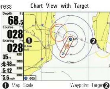
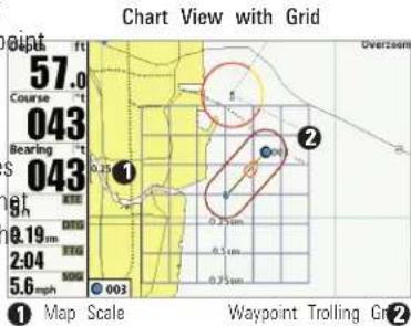
Add a Waypoint Target: Open the Waypoint Management dialog box and select a Waypoint. Press the RIGHT Cursor key, and select Target. Press the RIGHT Cursor key.
Add a Trolling Grid: Open the Waypoint Management dialog box and select a Waypoint. Press the RIGHT Cursor key, and select Grid. Press the RIGHT Cursor key. The grid can also be rotated to any heading by adjusting the Grid Rotation setting on the Navigation Main Menu.
Remove Target or Trolling Grid: Press the MENU key once, and choose Remove Target or Remove Grid from the Navigation X-Press™ Menu, and press the RIGHT Cursor key.
NOTE: Only one waypoint can have either a target or a grid applied to it at one time. If you apply a target or a grid to a new waypoint, the original waypoint will lose its target or grid.
NOTE: The spacing of the rings on the waypoint target and the spacing of the grid lines on the trolling grid are the same as the length of the scale bar on the left edge of the display. Zooming in or out will decrease or increase the spacing, respectively.
Routes
Save the Current Route: While you are navigating, the current route can be saved. From the Navigation X-Press™ Menu, select Save Current Route, and press the RIGHT Cursor key. Navigation will continue.
Create a New Route: Open the Waypoint Management dialog box. Select Options > New > New Route.
- New Route Dialog Box: Use the 4-WAY Cursor Control key to set the available fields (see Edit your Waypoints, Routes, Tracks, and Groups for details).
- Plan Route: Select Plan Route, and press the RIGHT Cursor key. The New Route dialog box closes so that you can select waypoints from the Waypoint Management dialog box. To add a selected waypoint to the route, press the RIGHT Cursor key. Repeat as needed. Select a Save and press the RIGHT Cursor key.
Adding Waypoints to a Route
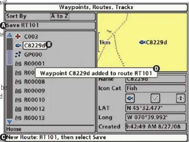
A Save:Press the EXIT key to choose Save. NewRouteInformation:Shows Press the RIGHT Cursor key to confirm the theRoute's name and next steps.
B SelectedWaypoint: Press the RIGHT Cursor key to add it to the Route. A confirmation displays each time D you add a waypoint to the Route.
Travel a Saved Route: Open the Waypoint Management dialog box. Select a saved route, and press the RIGHT Cursor key. Select Travel, and press RIGHT Cursor key. Select Forward to travel the route in order. Select Re to travel the route in reverse order.
Edit the Waypoint Order in a Route: Open the Waypoint Management dialog box. Select a Route, and press the RIGHT Cursor key to open the Route submenu. Select Open, and then choose one of the following opt
- Select Reverse, and press the RIGHT Cursor key. This will quickly reverse the order of the route. Press the EXIT key to select Save. Press the RIGHT Cursor key to confirm your changes.
OR
- Choose a Waypoint in a Route, and press the RIGHT Cursor key. Select Reorder, and press the RIGHT Cursor key. To move the waypoint up or down in the route order, press the UP or DOWN Cursor keys.
Press the EXIT key to select Save. Press the RIGHT Cursor key to confirm your changes.
Changing the Waypoint Order in a Route (two options)
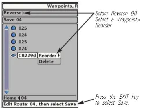
Review Route Information: Open the Waypoint Management dialog box. Select a saved route, and press the RIGHT Cursor key. Select info, and iims: RIGHT Cursor key. The Route Info dialog box displays the waypoints the route. The distance and bearing from each waypoint to the next, as as the distance and bearing from the current position to the first waypc the route will be displayed.
Delete a Saved Route: Open the Waypoint Management dialog box. Select saved route, and press the RIGHT Cursor key. Select Delete from the su and press the RIGHT Cursor key. To remove the route from the group, c Selected. To delete the route from all groups, choose All Instances.
^s Tracks
Save the Current Track: From the Navigation X-Press™ Menu, select Save Current Track, and press the RIGHT Cursor key. The track will remain or display but will change from black to gray. To remove the track complet from the display, see Hide or Display a Saved Track and Stop Tracking.
NOTE: When you save a track, a name is automatically assigned. The track n consists of a date/time stamp, but can be re-named later (see Edit your Waypoints, Routes, Tracks, and Groups).
Clear the Current Track: From the Navigation X-Press™ Menu, select Cle Current Track, and press the RIGHT Cursor key. The track will be removed from the display and permanently deleted.
Hide or Display a Saved Track: Open the Waypoint Management dialog box. Select a saved track, and press the RIGHT Cursor key. Select Edit the submenu. Use the 4-WAY Cursor Control key to set the track to vis hidden (see Edit your Waypoints, Routes, Tracks, and Groups for details).
Delete a Saved Track: Open the Waypoint Management dialog box. Select a saved track, and press the RIGHT Cursor key. Select Delete from the submenu, and press the RIGHT Cursor key. To remove the track from the group, choose Selected. To remove the track from all groups, choose All Instances. Edit your Waypoints, Routes, Tracks, and Groups Whether you are creating a new navigation item or editing it, you can the same steps to customize a waypoint, route, track, or group. The ava settings will depend on the type of item you are editing.
Stop Tracking: Press the MENU key twice to open the Main Menu. Select the Navigation Menu Tab > Current Track > Stop Tracking. Stop Tracking clears the current track, and the unit will not save trackpoints. See Navigation Menu Tab: Current Track for more information.
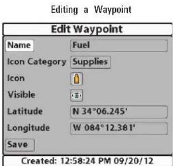
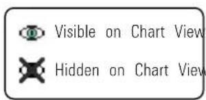
NOTE: The Edit Waypoint dialog box is also available when you select a way from the Navigation X-Press™ Menu.
NOTE: See your Humminbird® Waypoint Management Guide for more information about groups and the other great features of the Waypoint Management dialog box.
Edit a Waypoint, Route, Track, or Group
- Open the Waypoint Management dialog box.
- Open the Submenu: Use the 4-WAY Cursor Control key to select a waypoint, route, track, or group. Press the RIGHT Cursor key to open the submenu.
- Select Edit, and press the RIGHT Cursor key.
- Select a Field: Use the 4-Way Cursor Control key to move from field to field, and press the UP or DOWN Cursor keys to change the settings.
Name: Press the RIGHT or LEFT Cursor keys to move from space to space, and press the UP or DOWN Cursor keys to set the letter or number. All upper and lower case letters are available, as well as digits 0-9 and some punctuation symbols.
Icon Category: Press the UP or DOWN Cursor keys to scroll through the available categories. Select All to view all available icons. (All, Geometry, Alerts, Supplies, Navigation, Recreation, Fish, Environment)
Icon: Press the UP or DOWN Cursor keys to scroll through the available icons used to represent the waypoint in Chart View. The available icons are determined by the category selected in Icon Category.
Visible: Press the UP or DOWN Cursor keys to set the selected item to visible or hidden in the Chart View.
Latitude/Longitude: Press the RIGHT or LEFT Cursor keys to move from space to space, and press the UP or DOWN Cursor keys to the letter or number.
NOTE: The available settings will depend on the type of item you are editing.
Man Overboard (MOB) Navigation
As soon as you know that you have a man overboard (MOB), you show activate MOB navigation to maximize the chances for a successful rescue. MOB navigation allows you to create an MOB waypoint to locate the point at which your man went overboard and the relation of the boat to that
Activate MOB navigation: Press and hold the GOTO key for more than 1 seconds to activate the Man Overboard (MOB) function.
When MOB is activated, a MOB waypoint is created at the boat's current position, regardless of whether the chart cursor is active or not. The MOB waypoint has a large, distinctive icon. Once MOB is activated, any current navigation will be cancelled and the current route will be discarded without user notification. MOB navigation will begin immediately, and the MOB Vi will show the following:
- The view will switch to the Chart View, and the elapsed time since MOB was activated will be displayed.
- A line will be drawn from the boat's current position to the MOB waypoint, and the MOB waypoint will be targeted.
- The latitude/longitude position of the MOB waypoint will be displayed in an additional information box.
Cancel MOB Navigation: From the Navigation X-Press™ Menu, select Cancel MOB, and press the RIGHT Cursor key. Canceling MOB navigation removes the route and any waypoints created using the GOTO key but does not remove any saved routes from memory.
MOB Navigation
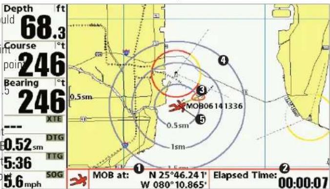
1 Position where man fell overboard Target surrounding MOB waypoint
② Elapsed time since MOB was activated MOB waypoint
3 Boat icon
It is not possible to re-activate MOB or modify the current route without first canceling MOB navigation. The Off Course trigger is also disabled and the Off Course Alarm circle is not drawn. Any press of the GOTO key, or selection of a GOTO menu option, will cause an error beep and a short message will be displayed that will disappear after 2 seconds.
The Menu System
The Menu System is divided into easy-to-use menu modules as follows. main components of the menu system are as follows:
- Start-Up Options Menu: Press the MENU key during the power on sequence to view the Start-Up Options Menu. From the Start-Up Options Menu, you can choose the following Fishfinder Modes: Normal, Simulator, and System Status.
- X-Press™ Menu: The X-Press™ Menu provides a shortcut to the most frequently-used settings, and the options on the X-Press™ Menu correspond with the current view.
- Main Menu: The Main Menu is a standard set of menu settings which are organized under the following tabbed headings: Alarms, Sonar, Navigation, Chart, Setup, Views, and Accessories.
NOTE: The X-Press™ Menu(s) and the Main Menu options can also be expanded or simplified by setting the User Mode to Advanced or Normal (see Main Menu: User Mode).
Start-Up Options Menu
Press the MENU key during the power on sequence to view the Start-L Options Menu, and select one of the modes described on the following pages. Also, see Power On for more information.
Start-Up Options Menu
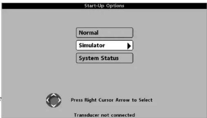
Normal
Use Normal for on-the-water operation with a transducer connected. If a functioning transducer is connected, Normal operation will be selected automatically at power up, and your Fishing System can be used on the
To exit Normal operation, power off your Fishing System.
Simulator
System Status
Use Simulator to learn how to use your Fishfinder before taking your book the System Status to view system connections and to conduct a unit s on the water. The Simulator is a very powerful tool that provides a randomly-updated display which simulates on the water operation. After you select System Status from the Start-Up Options Menu press it
Simulator
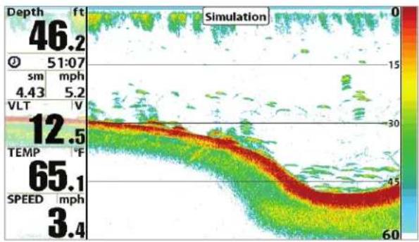
heatmap
| Depth (ft) | Temperature (°C) | |------------|------------------| | 46.2 | 65.1 | | 51:07 | 65.1 | | 4.43 | 65.1 | | 5.2 | 65.1 | | 12.5 | 65.1 | | 30 | 65.1 | | 60 | 65.1 |We recommend going through this manual while using the Simulator, since all of the menus function and affect the display in the same way as they would in Normal operation. Any menu changes you make will be saved for later use.
- A message will appear often on the display to indicate Simulator mode.
• To exit Simulator, power off your Fishing System.
NOTE: It is important to select Simulator manually from the Start-Up Options Menu as opposed to letting the Fishing System enter Simulator automatically (as it will if a transducer is not connected and you do nothing during power up).
After you select System Status from the Start-Up Options Menu, press the VIEW key to display the following options:
- Self Test
- Accessory Test
• GPS Diagnostic View
To exit System Status, power off your Fishing System.
Self Test displays results from the internal diagnostic self test, including serial number, Printed Circuit Board (PCB) serial number, software revision total hours of operation, and the input voltage.
Self Test Screen
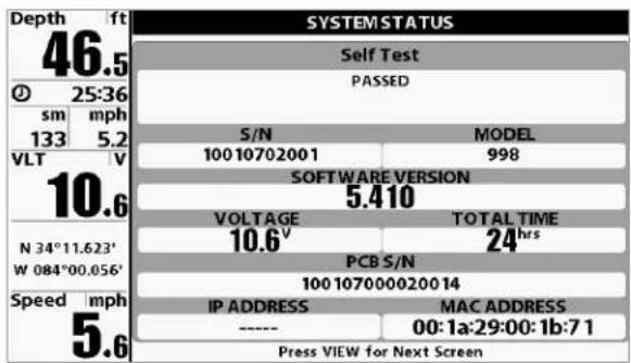
Accessory Test lists the accessories connected to the system.
Accessory Test Screen
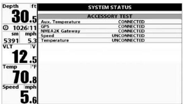
NOTE: The speed accessory will be detected only if the paddlewheel has moved 1 Sky Chart Current Latitude and Longitude since your Fishing System was powered up. 2 Satellite Being Used
GPS Diagnostic View
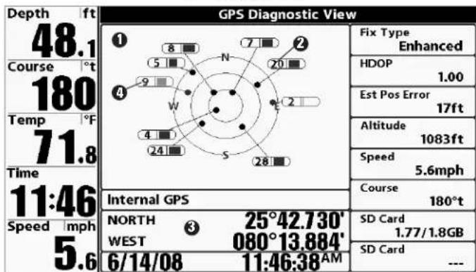
3
Satellite Being Monitored 4
GPS Diagnostic View shows a sky chart and numerical data from the GPS receiver. The sky chart shows the location of each visible GPS satellite with its satellite number and a signal strength bar. A dark gray bar indicates that the satellite is being used to determine your current position. A light gray bar indicates that the satellite is being monitored, but is not yet being used.
This view also reports the current position, local time and date, and other numeric information. The current GPS Fix Type is reported as No Fix, 2D Fix, 3D Fix, or Enhanced. An Enhanced fix has been augmented using information from WAAS, EGNOS, or MSAS. A 3D or Enhanced Fix is required for navigation. HDOP (the Horizontal Dilution of Precision) is a GPS system parameter which depends on the current satellite configuration. HDOP is used to calculate the Estimated Position Error.
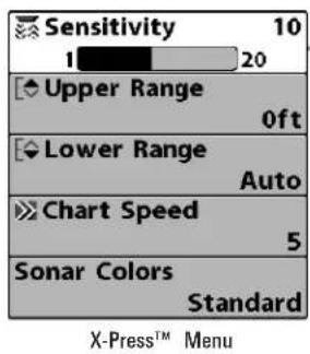
X-Press™ Menu
The X-Press™ Menu provides a shortcut to your most frequently-used settings. The options provided on the X-Press™ Menu correspond with the current view. For example, if you are in a Sonar View and press the MENU key once, the Sonar X-Press™ Menu will display.
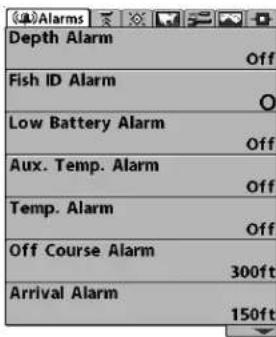
Main Menu System, Normal User Mode
Main Menu
The Main Menu provides the standard set of menu options, including the settings that are changed less frequently. The Main Menu is organized under the following tabs to help you find a specific menu item quickly: Alarms, Sonar, Navigation, Chart, Setup, Views, and Accessories.
NOTE: Menu options can be expanded or simplified by setting the User Mode to Advanced or Normal. See Main Menu: User Mode for details.
To use an X-Press™ Menu
- In any view, press the MENU key once.
- Press the UP or DOWN Cursor keys to highlight an X-Press™ Menu. To use the Main Menu: option, then use the RIGHT or LEFT Cursor keys to change the menu1. In any view, press the MENU key twice. setting.
NOTE: The X-Press™ Menu will collapse temporarily and the screen will update if it is affected by your menu setting change, which allows you to see the effects of your change immediately.
- Reactivate the X-Press™ Menu by pressing the UP or DOWN Cursor keys.
Total Screen Update™ - When you change any menu settings that affect the current view, the view will update immediately (i.e. you don't have to exit the menu to apply the change to the screen).
Menu options can be simplified or expanded by setting the User Mode to Normal or Advanced. SeeMainMenu:UserModefor details.
To use the Main Menu:
- Press the RIGHT or LEFT Cursor keys to highlight a menu tab.
- Press the DOWN or UP Cursor keys to select a specific menu option under that tab.
-
Press the RIGHT or LEFT Cursor keys again to change a menu setti
-
A down arrow at the bottom of a menu means that you can scroll to additional menu options using the DOWN Cursor key.
- A right or left arrow on a menu option means that you can use the RIGHT or LEFT Cursor keys to make changes or to see more information.
- Press the EXIT key to move quickly to the top of the tab.
Total Screen Update™ - When you change any menu settings that affect the current view, the view will update immediately (i.e. you don't have to exit the menu to apply the change to the screen).
Quick Tips for the Main Menu
- From any menu option on a menu tab, press the EXIT key to directly to the top of the tab.
- From the bottom of a menu tab, press the DOWN Cursor key to jump directly to the top of the tab.
- From the top of a menu tab, press the LEFT or RIGHT Cursor keys to scroll to the next tab. You can also jump to the beginning or end of the tab rotation by repeatedly pressing the RIGHT or LEFT Cursor keys.
- If there is a down arrow at the bottom of a menu tab, press the DOWN Cursor key to scroll to additional menu options.
- If there is a right or left arrow on a menu option, press the RIGHT or LEFT Cursor keys to make setting changes or see more information.
- If you press MENU or EXIT to leave the Main Menu and then return to the Main Menu at a later time, the menu will open to the same tab as the last time the Main Menu was displayed.
Note for all Menu Settings
The settings in all menus are adjusted in the same way. Simply use the WAY Cursor Control key to highlight a menu option, and then change the settings or activate the option (see Main Menu or X-Press™ Menu).
Below is an example of how the menu options are described in this map. Each description shows the menu option appearance, the available settings and the specific control head settings required (i.e. advanced user mode, international only, view, navigation, or accessory).
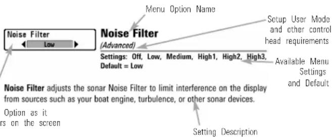
User Mode (Normal or Advanced)
Menu options can be simplified or expanded by setting your Fishing System User Mode to Normal or Advanced.
Normal Mode is provided for users who want greater simplicity and fewer menu choices.
Advanced Mode is provided for users who want the highest level of control over the Fishing System. Several menu settings are added to the Main Men when the User Mode is changed to Advanced. Advanced mode is the default setting when you first power on your Humminbird® Fishing System.
To change the User Mode setting:
- Press the MENU key twice to access the Main Menu.
- Press the RIGHT Cursor key until the Setup tab is selected.
- Press the DOWN Cursor key to highlight User Mode on the Setup main menu.
- Press the LEFT or RIGHT Cursor keys to change the User Mode setting. (Normal, Advanced, Default = Advanced)
NOTE: Any changes made while in Advanced Mode will remain in effect after you switch back to Normal Mode.
For example, the Select Readouts menu option is available when the User Mode is set to Advanced. If you change the Select Readouts settings while operating in Advanced User mode, the Select Readouts you choose will continue to display on the screen even if you switch back to Normal User Mode.
| Beam Select | 200kHz |
| Imaging Frequency | 455kHz |
| Surface Clutter | 5 |
| SwitchFire | Clear Mode |
| Fish ID + | Off |
| Fish ID Sensitivity | 5 |
| RTS Window | Narrow |
| Sonar Colors | Original Palette |
| Bottom View | Structure ID |
| Zoom Width | Narrow |
| SI Readouts | On |
| Connected TransducerHi-Def SideScan | |
| Color Bar | On |
| Temperature Graph | On |
| DI Colors | Blue |
999ci HD SI Sonar Tab, Normal Mode
| Beam Select | |
| 83kHz | |
| Imaging Frequency | |
| 455kHz | |
| Surface Clutter | |
| 5 | |
| SwitchFire | |
| Clear Mode | |
| Fish ID + | |
| Off | |
| Fish ID Sensitivity | |
| 5 | |
| RTS Window | |
| Narrow | |
| Sonar Colors | |
| Original Palette | |
| Bottom View | |
| Structure ID | |
| Zoom Width | |
| Narrow | |
| 83kHz Sensitivity | |
| 0 | |
| 455kHz Sensitivity | |
| 0 | |
| Depth Lines | |
| On | |
| SI Range Lines | |
| Off | |
| SI Readouts | |
| On | |
| Noise Filter | |
| Off | |
| Max Depth | |
| Auto | |
| Water Type | |
| Fresh | |
| Connected Transducer | |
| Hi-Def Sidescan | |
| Color Bar | |
| On | |
| Temperature Graph | |
| Off | |
| Down Imaging Beam Width | |
| Wide | |
| DI Colors | |
| Blue | |
| Cancel Navigation | |
| Active SideLeft | |
| Split Position50 | |
| Sensitivity10 | |
| Upper Range0ft | |
| Lower RangeAuto | |
| Chart Speed5 | |
| Quad LayoutDefault | |
| Bottom LockOff | |
| Bottom Range15ft | |
999ci HD SI
Sonar Tab, Advanced Mode
Sonar X-Press™ Menu (shown with optional-purchase transducer menu options)
Sonar X-Press™ Menu
The Sonar X-Press™ Menu provides a shortcut to your most frequently-used settings. Press the MENU key once while in any of the Sonar Views to access the Sonar X-Press™ Menu.
NOTE: Menu options can be expanded or simplified by setting the User Mode to Advanced or Normal. See Main Menu: User Mode for details.
NOTE: The selected transducer also influences the menu options. See Sonar Menu Tab: Connected Transducer for more information.
NOTE: Menu options are determined by your Humminbird® model. See the following pages for full menu descriptions.
Cancel Navigation
Cancel Navigation
(only when Navigating)
Settings: Press the RIGHT Cursor key and follow screen instructions.
Cancel Navigation discards the current route and exits Navigation Mode. This menu option will only appear when you are currently navigating a This will not delete a previously-saved route.
Active Side Left
Active Side
(Combo Views only)
Settings: Left, Right, Default = Left
Active Side allows you to select a side of the screen in a Combo View you choose an active side, you can apply menu settings and key comma to the view you've selected. The Active Side menu option is only available when a Combo View is on the screen (see Views: Combo Views).
- A green arrow on the Combo View points to the active side.
- When a menu is displayed in the active side, the non-active side of the screen will be grayed out.
Split Position 50 Left Right
Split Position
(Combo Views only)
Settings: Left, 30, 40, 50, 60, 70, Right, Default = Various
Split Position sets the size of the left side of the Combo View. Each C View can be set individually. The Split Position menu option is only avai when a Combo View is on the screen (see Views: Combo Views).
- The number setting indicates the percentage taken up by the left side of the Combo View.
- Selecting Left sets the left side of the screen to its smallest setting.
- The number setting indicates the percentage taken up by the left side of the Combo View.
- Selecting Left sets the left side of the screen to its smallest setting.
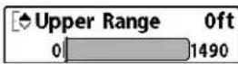
Upper Range
(Advanced: Sonar, Split Sonar and
Active Sonar Side Views only)
Settings: Various, see below.
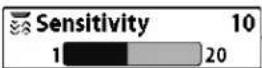
Sensitivity
Settings: Low = 1, High = 20; Default = 10
Sensitivity controls how much detail is shown on the display and will the sensitivity of all sonar frequencies.
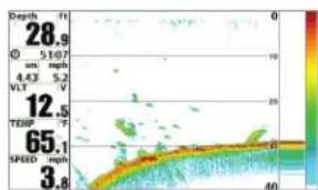
heatmap
| Depth (ft) | Value | |---|---| | 28.9 | 0 | | 51.07 | 10 | | 4.43 | 20 | | 5.2 | 25 | | 12.5 | 30 | | 65.1 | 35 | | 3.8 | 40 |Sensitivity at Low
Decrease the sensitivity to eliminate the clutter from the display that is sometimes present in murky or muddy water. If Sensitivity is adjusted too low, the display may not show many sonar returns that could be fish.
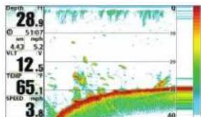
heatmap
| Depth | Value | |---|---| | 28.9 | 10 | | 12.5 | 20 | | 65.1 | 30 | | 3.8 | 40 |Sensitivity at Medium
When operating in very clear water or greater depths, increase the sensitivity to see weaker returns that may be of interest. If the sensitivity is adjusted too high, the display may become too cluttered.
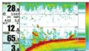
heatmap
| Depth (mm) | Value | |---|---| | 28.9 | | | 5107 | | | 4.43 | 5.2 | | 4.43 | V | | 12.5 | | | 65.1 | | | 3.8 | |Sensitivity at High
NOTE: The Sensitivity setting is a global setting and will adjust the sensitivity of all sonar frequencies.
Upper Range sets the shallowest depth range that will be displayed on Sonar, Split Sonar, and Active Sonar Side Views. Upper Range is often adjusted lower range.
For example, if you are only interested in the area between 20 and 50 feet deep, you should set the Upper Depth Range to 20 and the Lower Depth Range to 50. The Sonar View will then show the 30 foot area between 20 and 50, and will not show the surface or the bottom (assuming the bottom is deeper than 50 feet), and will show greater detail for that area between 20 and 50 feet.
NOTE: A minimum distance of 10 feet will be maintained between the Upper Lower Range regardless of the manual settings entered.
The available Upper Range settings are determined by your Humminbird® model as follows:
- 859ci HD/959ci HD: 0 to 1490 ft, 0 to 497 m (International Model only); Default = 0
- 859ci HD DI/959ci HD DI: 0 to 1490 ft, 0 to 497 m (International Models only); Default = 0
- 899ci HD SI/999ci HD SI: 0 to 1490 ft, 0 to 497 m (International Models only); Default = 0
- 859ci HD XD/959ci HD XD: 0 to 3270 ft, 0 to 997 m (International Models only); Default = 0
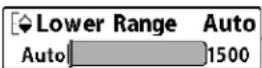
Lower Range
Settings: Various, see below.
Lower Range sets the deepest depth range that will be displayed by the
Auto: The Lower Range will be adjusted by the unit to follow the bottom automatically. Auto is the default setting.
Manual: You can adjust the Lower Range to lock the unit on a particular depth. M be displayed in the lower right corner of the screen to indicate the unit is in Manual mode. Adjust the Upper and Lower Range together to view a specific depth range, especially when looking for fish bottom structure.
For example, if you are fishing in 60 feet of water but are only interested in the first 30 feet (surface to a depth of 30 feet) you should set the Lower Depth Range limit to 30. The display will show the 0 to 30 foot range, which allows you to see a more detailed view than you would see if the display went all the way to the bottom.
NOTE: A minimum distance of 10 feet will be maintained between the Upper Lower Range regardless of the settings entered manually.
The available Lower Range settings are determined by your Humminbird® model as follows:
- 859ci HD/959ci HD: Auto to 1500 ft, Auto to 500 m (International Models only); Default = Auto
-
859ci HD DI/959ci HD DI: Auto to 1500 ft, Auto to 500 m (International Models only); Default = Auto
-
899ci HD SI/999ci HD SI: Auto to 1500 ft, Auto to 500 m (International Models only); Default = Auto
859ci HD XD/959ci HD XD: Auto to 3280 ft, Auto to 1000 m (International Models only); Default = Auto
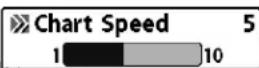
Chart Speed
Settings: 1 to 10, where 1 = Slow, 10 = Fastest; Default = 5
Chart Speed determines the speed at which the sonar information moves across the display, and consequently the amount of detail shown.
A faster speed shows more information and is preferred by most angler: however, the sonar information moves across the display quickly. A slow speed keeps the information on the display longer, but the bottom and details become compressed and may be difficult to interpret. Regardless the Chart Speed setting, the RTS Window ^™ will update at the maximum possible for the depth conditions.
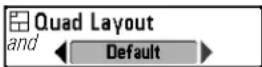
Quad Layout
(with optional-purchase QuadraBeam PLUS™ Transducer, Side Beam View only)
Settings: Default, Classic, Slanted, Default = Default
Quad Layout allows you to choose how sonar information is displayed in Side Beam View. The Side Beam View displays sonar data from the left right 455 kHz beams, as well as the 200 kHz down-looking beam. The s data can be displayed in any of the following layouts by changing the Layout setting: Default, Classic, and Slanted. See Views: Side Beam View for more information.
NOTE: Quad Layout is only available when an optional-purchase QuadraBeam PLUS™ transducer is attached and the Side Beam View is active (see Sonar Menu Tab: Connected Transducer).
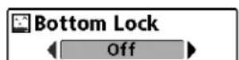
Bottom Lock
(Sonar Zoom View only)
Settings: Off, On; Default = Off
Bottom Lock changes the mode of the zoomed view in the Sonar Zoom View. Bottom Lock continuously graphs the bottom at a constant point of the display regardless of changes in depth. This "flattens" out the bottom contour but is effective at showing fish on or near the bottom.
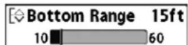
Bottom Range
(Sonar Zoom View only, when Bottom Lock is Settings: 10 to 60 feet, 2 to 10 fathoms, or 3 to meters [International Models only]; Default = 15 feet
Bottom Range allows you to control how much of the water column, measured up from the bottom, is shown in the Sonar Zoom View. Choose a small value to see low-lying bottom structure or details of the bottom return. Choose a larger value to see large structure in deeper water.
NOTE: It is possible to set the Bottom Range to be greater than the depth. In this case, you may see surface clutter in a wavy band that mirrors changes in the depth.
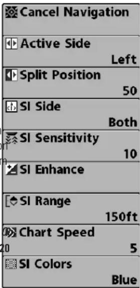
Side Imaging® X-Press™ Menu
Side Imaging® X-Press™ Menu
(Side Imaging ^® Views only [899ci HD SI and 999ci HD SI])
The Side Imaging ^® X-Press ^™ Menu provides a shortcut to your most frequently-used settings. Press the MENU key once while in any of the Side Imaging ^® Views to access the Side Imaging ^® X-Press ^™ Menu.
NOTE: Menu options can be expanded or simplified by setting the User Mode to Advanced or Normal. See Main Menu: User Mode for details.

Cancel Navigation (only when Navigating)
Settings: Press the RIGHT Cursor key and follow screen instructions.
Cancel Navigation discards the current route and exits Navigation Mode. This menu option will only appear when you are currently navigating a This will not delete a previously-saved route.
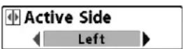
Active Side
(Combo Views only)
Settings: Left, Right, Default = Left
Active Side allows you to select a side of the screen in a Combo View.
you choose an active side, you can apply menu settings and key commands to the view you've selected. The Active Side menu option is only available
when a Combo View is on the screen (see Views: Combo Views).
- A green arrow on the Combo View points to the active side.
- When a menu is displayed in the active side, the non-active side the screen will be grayed out.
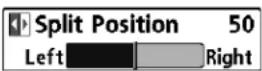
Split Position
(Combo Views only)
Settings: Left, 30, 40, 50, 60, 70, Right; Default = Various
Split Position sets the size of the left side of the Combo View. Each Combo View can be set individually. The Split Position menu option is only available when a Combo View is on the screen (see Views: Combo Views).
- The number setting indicates the percentage taken up by the left side of the Combo View.
- Selecting Left sets the left side of the screen to its smallest setting
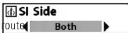
SI Side
Settings: Left, Both, Right, Default = Both
SI Side sets which transducer beam from the Side Imaging® beams will shown on the display.
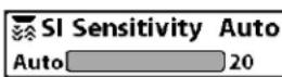
SI Sensitivity
Settings: 1 to 20, where Low = 1, High = 20, Default = 10
SI Sensitivity controls how much detail is shown on the display.
Increase the SI Sensitivity to reveal weaker returns that may be of inte especially in very clear water or greater depths. A high SI Sensitivity set shows more sonar returns from small baitfish and suspended debris in tl water; however if the SI Sensitivity is adjusted too high, the display ma become too cluttered.
Decrease the SI Sensitivity to eliminate the clutter from the display that sometimes present in murky or muddy water. If SI Sensitivity is adjusted low, the display may not show many sonar returns that could be fish.
SI Enhance
SI Enhance
Settings: Press the RIGHT Cursor key.
SI Enhance allows you to adjust your Side Imaging® View in four categories: Sensitivity, Contrast, Sharpness, and Contour Mode.
Whether you're searching the Side Imaging® data for fish or certain bottom contour, the most effective settings will vary with the situation. The display will update as you adjust each category. SI Enhance can also be used during Recording Playback (see Snapshot and Recording View).
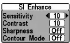
SI Enhance Submenu
- Sensitivity - Controls how much detail is shown on the display. When operating in very clear water or greater depths, increased sensitivity shows weaker returns that may be of interest. Decreasing the sensitivity eliminates the clutter from the display that is sometimes present in murky or muddy water. (1 to 20, where Low = 1, High = 20, Default = 10)
NOTE: The Sensitivity can be adjusted from the SI Enhance dialog box or the Side Imaging® X-Press™ Menu. The Sensitivity setting is provided here so that you can easily adjust the Side Imaging® data with the other settings. See Side Imaging® X-Press™ Menu: SI Sensitivity for more information.
- Contrast: Accents the light and dark parts of the Side Imaging® data to provide greater definition. (1 to 20, Default = 10)
- Sharpness: Filters the view and sharpens the edges of the Side Imaging® data. (Low (L), Medium (M), High (H), Default = Off)
- Contour Mode: Controls how the water column is displayed in the Side Imaging® Views. In the normal display with the Contour Mode y off, the water column is displayed on the view. The location of a target on the display is based on the slant range to the target.
When Contour Mode is turned on, the bottom is graphed at a constant point on the display, regardless of changes in depth. The Side Imaging ^® beams are divided by a vertical line. The water column is removed from the view, which allows the display to show targets at their linear horizontal distance. The location of a target may be easier to interpret when the water column is removed. (Off, On; Default = Off)
NOTE: If both SI Range Lines and Contour Mode are turned on, the SI Range Lines will remain on the display, but the individual range numbers are not available (see Sonar Menu Tab: SI Range Lines).
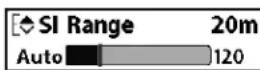
SI Range
Settings: Auto, 6 to 360 feet, or 2 to 120 meters [International Models only], Default = 150 feet, 50 meters
SI Range sets the deepest range that will be displayed in the Side Imaging views. The range must be set manually.
Choose a low range number to focus on a shorter distance of the water column and see greater detail on the screen. Choose a higher range number to view farther into the water and see an overview of details on the screen.
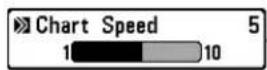
Chart Speed
Settings: 1 to 10, where 1 = Slow, 10 = Fastest, Default = 5
Chart Speed determines the speed at which the side sonar information moves down the display, and consequently the amount of detail shown. faster speed shows more information in the Side Imaging® Views and is preferred by most anglers; however, the sonar information moves across display quickly. A slower speed keeps the information on the display for which allows you to see an entire area.
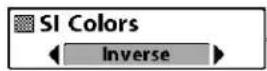
SI Colors
Settings: Blue, Amber 1, Amber 2, Brown, Green, Inverse, Gray, Green/Red, Default = Amber 1
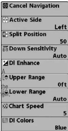
Down Imaging ^® X-Press ^TM Menu
Down Imaging® X-Press™ Menu (Down Imaging® Views only [859ci HD DI, 959. HD DI, 899ci HD SI, and 999ci HD SI])
The Down Imaging® X-Press™ Menu provides a shortcut to your most frequently-used settings. Press the MENU key once while in any of the Down Imaging® Views to access the Down Imaging® X-Press™ Menu.
NOTE: Menu options can be expanded or simplified by setting the User Mode to Advanced or Normal. See Main Menu: User Mode for details.
NOTE: Menu options are determined by your Humminbird® model. See the following pages for full menu descriptions.
SI Colors allows you to select which color palette you would like to use for the Side Imaging® display.

Cancel Navigation (only when Navigating)
Settings: Press the RIGHT Cursor key and follow screen instructions.
Cancel Navigation discards the current route and exits Navigation Mode. This menu option will only appear when you are currently navigating a This will not delete a previously-saved route.
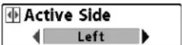
Active Side (Combo Views only)
Settings: Left, Right, Default = Left
Active Side allows you to select a side of the screen in a Combo View you choose an active side, you can apply menu settings and key commands to the view you've selected. The Active Side menu option is only available when a Combo View is on the screen (see Views: Combo Views).
- A green arrow on the Combo View points to the active side.
- When a menu is displayed in the active side, the non-active side the screen will be grayed out.
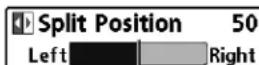
Split Position
(Combo Views only)
Settings: Left, 30, 40, 50, 60, 70, Right, Default = Various
Split Position sets the size of the left side of the Combo View. Each View can be set individually. The Split Position menu option is only as when a Combo View is on the screen (see Views: Combo Views).
- The number setting indicates the percentage taken up by the left side of the Combo View.
- Selecting Left sets the left side of the screen to its smallest setting
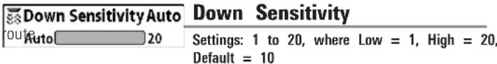
Down Sensitivity controls how the sonar returns are displayed on the D Imaging® Views.
Increase the Down Sensitivity to reveal weaker returns that may be of interest, especially in very clear water or greater depths. A high Down Imaging® Sensitivity setting shows more sonar returns from small baitfish and suspended debris in the water; however if the Down Imaging® Sensitivity is adjusted too high, the display may become too cluttered.
Decrease the Down Sensitivity to eliminate the clutter from the display is sometimes present in murky or muddy water. If Down Imaging® Sensi is adjusted too low, the display may not show many sonar returns that die fish.

DI Enhance allows you to adjust your Down Imaging® View in the follow categories: Sensitivity, Contrast, and Sharpness.
Whether you're searching the Down Imaging® data for fish or certain bo Contour, the most effective settings will vary with the situation. The disp ableupdate as you adjust each category. DI Enhance can also be used Recording Playback (see Views: Snapshot and Recording View).
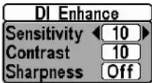
DI Enhance Submenu
- Sensitivity: Controls how much detail is shown on the display. When operating in very clear water or greater depths, increased sensitivity shows weaker returns that may be of interest. Decreasing the sensitivity eliminates the clutter from the display that is sometimes present in murky or muddy water. (1 to 20, where Low = 1, High Default = 10)
NOTE: The Sensitivity can be adjusted from the DI Enhance dialog box or the Imaging® X-Press™ Menu. The Sensitivity setting is provided here so that you can easily adjust the Down Imaging® data with the other set Down Imaging® X-Press™ Menu: Down Sensitivity for more information.
- Contrast: Accents the light and dark parts of the Down Imaging® data to provide greater definition. (1 to 20, Default = 10)
- Sharpness Filters the view and sharpens the edges of the Down Imaging® data. (Low (L), Medium (M), High (H), Default = Off)
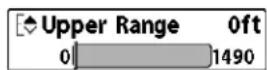
Upper Range
(Advanced, Down Imaging® Views only)
Settings: 0 to 1490 feet or 0 to 497 meters [International models only], Default = 0
Upper Range sets the shallowest depth range that will be displayed on Down Imaging ^® Views. Upper Range is often used with Lower Range.
For example, if you are only interested in the area between 20 and 50 feet deep, you should set the Upper Depth Range to 20 and the Lower Depth Range to 50. The Down Imaging® View will then show the 30 foot area between 20 and 50, and will not show the surface or the bottom (assuming the bottom is deeper than 50 feet), and will show greater detail for that area between 20 and 50 feet.
NOTE: A minimum distance of 10 feet will be maintained between the Upper Lower Range regardless of the manual settings entered.
![- 20: Lower Range Auto Auto 1500 Down Lower Range Settings: Auto to 1500 feet, Auto to 500 meters [International Models only]; Default = Auto](/content/2026/06/1204388/images/bbfa414a6e9f3d9e35fba397156fab742b50172d56bd55ea0853b7a87f1cc8f2.jpg)
"Lower Range sets the deepest depth range that will be displayed by th
Auto: The Lower Range will be adjusted by the unit to follow the bottle automatically. Auto is the default setting.
Manual: You can adjust the Lower Range to lock the unit on a particular depth. Ml be displayed in the lower right corner of the screen to indicate the unit is in Manual mode. Adjust the Upper and Lower Range together to view a specific depth range, especially when looking for fish bottom structure.
For example, if you are fishing in 60 feet of water but are only interested in the first 30 feet (surface to a depth of 30 feet) you should set the Lower Depth Range limit to 30. The display will show the 0 to 30 foot range, which allows you to see a more detailed view than you would see if the display went all the way to the bottom.
NOTE: A minimum distance of 10 feet will be maintained between the Upper Lower Range regardless of the settings entered manually.
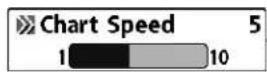
Chart Speed
Settings: 1 to 10, where 1 = Slow, 10 = Fastest, Default = 5
Chart Speed determines the speed at which the sonar information moves across the display, and consequently the amount of detail shown.
A faster speed shows more information and is preferred by most anglers however, the sonar information moves across the display quickly. A slow speed keeps the information on the display longer, but the bottom and details become compressed and may be difficult to interpret.
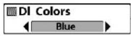
DI Colors
Settings: Blue, Amber 1, Amber 2, Brown, Green, Inverse, Gray, Green/Red, Default = Amber 1
DI Colors allows you to select which color palette you would like to us the Down Imaging® display.
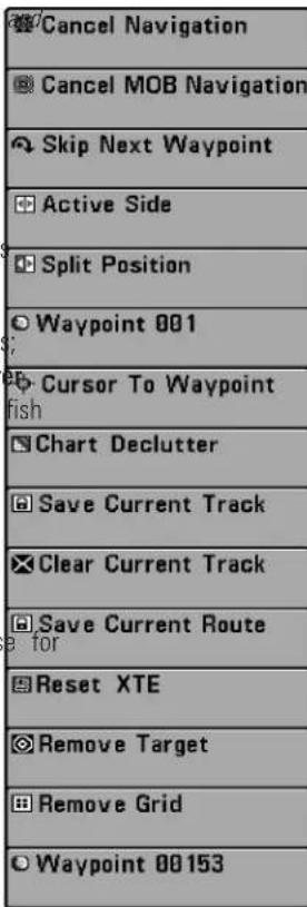
Navigation X-Press™ Menu
The Navigation X-Press™ Menu provides a shortcut to your most frequently-used settings. Press the MENU key once while in the Bird's Eye View, Chart View, or Chart Combo Views to access the Navigation X-Press™ Menu.
NOTE: Menu options will vary depending on system settings, such as whether you are currently navigating.
NOTE: Menu options can be expanded or simplified by setting the User Mode to Advanced or Normal. See Main Menu: User Mode for details.
NOTE: To see the Navigation X-Press™ Menu in a Combo View, change the Active Side setting to the side you want to adjust.
See Introduction to Navigation and the Humminbird® Waypoint Management Guide for more information.
Navigation X-Press™ Menu

Cancel Navigation
(only when Navigating)
Settings: Press the RIGHT Cursor key and follow screen instructions.
Cancel Navigation discards the current route and exits Navigation Mode. This menu option will only appear when you are currently navigating a This will not delete a previously-saved route.
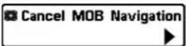
Cancel MOB Navigation
(only when MOB Navigation is activated)
Settings: Press the RIGHT Cursor key and follow screen instructions.
Cancel MOB Navigation removes the Man Overboard (MOB) waypoint and exits Man Overboard mode. This menu option will only appear when you currently navigating in Man Overboard mode.
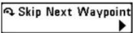
Skip Next Waypoint
(only when Navigating)
Settings: Press the RIGHT Cursor key and follow screen instructions.
Skip Next Waypoint removes the next waypoint from the current route. menu option will only appear when you are currently navigating a route.
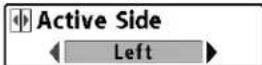
Active Side
(Combo Views only)
Settings: Left, Right, Default = Left
Active Side allows you to select a side of the screen in a Combo View. You choose an active side, you can apply menu settings and key commands to the view you've selected. The Active Side menu option is only available when a Combo View is on the screen (see Views: Combo Views).
- A green arrow on the Combo View points to the active side.
- When a menu is displayed in the active side, the non-active side of the screen will be grayed out.
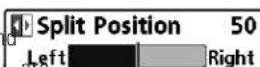
Split Position
(Combo Views only)
Settings: Left, 30, 40, 50, 60, 70, Right, Default = Various
Split Position sets the size of the left side of the Combo View. Each C View can be set individually. The Split Position menu option is only avai when a Combo View is on the screen (see Views: Combo Views).
- The number setting indicates the percentage taken up by the left s his of the Combo View.
- Selecting Left sets the left side of the screen to its smallest setting
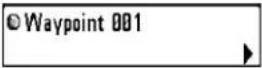
Waypoint [Name]
(Only with an active cursor on a waypoint)
Settings: Edit, Delete, Target, Grid
Waypoint [Name] allows you to view the Waypoints submenu for the waypoint under your cursor. You can move the cursor onto an existing waypoint and press the MENU key once, or use Cursor to Waypoint select a waypoint from the saved waypoints list.
NOTE: See Introduction to Navigation and the Humminbird® Waypoint Management Guide for more information.
The Waypoint Submenu includes the following menu options:
Edit opens the Edit Waypoint dialog box so that you can edit the selected waypoint. See Introduction to Navigation and the Humminbird® Waypoint Management Guide for more information.
Delete allows you to delete the waypoint.
Target applies a target to the waypoint.
Grid applies a trolling grid to the waypoint.
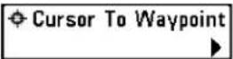
Cursor to Waypoint
(Chart or Chart Combo View only)
Settings: Press the RIGHT Cursor key and follow screen instructions.
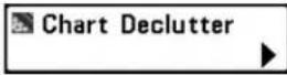
Chart Declutter
Settings: Press the RIGHT Cursor key to activate.
Chart Declutter removes all chart layers except for land outlines, waypoint routes, and tracks. The chart will stay decluttered for 10 seconds, and it will refresh to its previous display settings. To refresh the view faster to 10 seconds, press the +/- Zoom keys.
NOTE: See Chart Menu Tab: Chart Detail Level for more information.
Save Current Track
Settings: Press the RIGHT Cursor key and follow screen instructions.
Save Current Track allows you to save the current track on the display. the current track is saved, a new current track is started. Save Current appears on the Navigation X-Press™ Menu after navigation is stopped.
NOTE: To save the depth information with the current track, it is important to save the track and also edit the name before powering off the control head.
Clear Current Track
Settings: Press the RIGHT Cursor key and follow screen instructions.
Cursor to Waypoint allows you to quickly move the cursor to any saved. Clear Current Track allows you to clear the current track on the display, waypoint so that you can locate it or edit it. This X-Press™ Menu option only a new track at the present position. appears if you have saved waypoints.
Save Current Route
(only when Navigating)
Settings: Press the RIGHT Cursor key and follow screen instructions.
Save Current Route allows you to save the current route being displayed. This menu option will only appear when you are currently navigating a r
Reset XTE
(only when Navigating)
Settings: Press the RIGHT Cursor key to activate.
Reset XTE is available during navigation. When it is selected, the cross error (XTE) will be recalculated from the boat's current position to the waypoint in the route.
For example, when you've deviated from a route to navigate around an island, select Reset XTE to update the unit's course calculations from the current boat position instead of from the previous waypoint in the route.
Remove Target
(only if a Target is Active)
Settings: Press the RIGHT Cursor key to activate.
Remove Target removes the waypoint target from the display. This menu option will only appear when a target has already been applied to a waypoint.
NOTE: See Introduction to Navigation: Add a Waypoint Target or Trolling for more information.
Remove Grid
(only if a Grid is Active)
Settings: Press the RIGHT Cursor key to activate.
Remove Grid removes the waypoint grid from the display. This menu op will only appear when a grid has already been applied to a waypoint. route.
NOTE: See Introduction to Navigation: Add a Waypoint Target or Trol. for more information.
Waypoint [Name]
(Most recently-created waypoint)
Settings: Edit, Delete, Go To, Target, Grid
Waypoint [Name] allows you to view the waypoints submenu for the most recently created waypoint. You must have pressed the MARK key at least since you last powered up the Fishfinder for this menu option to appeal
NOTE: See Introduction to Navigation and the Humminbird® Waypoint Management Guide for more information.
The Waypoint Submenu includes the following menu options:
Edit opens the Edit Waypoint dialog box so that you can edit the selected waypoint. See Introduction to Navigation and the Humminbird® Waypoint Management Guide for more information.
Delete allows you to delete the waypoint.
Go To starts navigation to the waypoint.
Target applies a target to the waypoint.
Grid applies a trolling grid to the waypoint.
| Cancel Navigation |
| Start Recording |
| Stop Recording |
| Delete Image |
| Delete All Images |
| Delete Recording |
| Delete All Recordings |
| Pings Per Second Auto |
| Playback Speed |
| Stop Playback |
Snapshot and Recording X-Press™ Menu
Snapshot and Recording X-Press™ Menu
(Snapshot and Recording View only)
The Snapshot and Recording X-Press™ Menu provides access to the snapshot management and sonar recording functions. Press the MENU key once while in the Snapshot and Recording View to access the Snapshot and Recording X-Press™ Menu.
NOTE: For more information, see Views: Snapshot and Recording View.

Cancel Navigation
(only when Navigating)
Settings: Press the RIGHT Cursor key and follow screen instructions.
Cancel Navigation discards the current route and exits Navigation Mode. This menu option will only appear when you are currently navigating a This will not delete a previously-saved route.

Start Recording
(optional-purchase SD Memory Card, Snapshot and Recording View only)
Settings: Press the RIGHT Cursor key to activate.
Start Recording allows you to start sonar recording from the Snapshot & Recording View. This menu option is only available when an optional-purchase SD memory card is installed and Snapshot and Recording View on the screen.
Stop Recording
(optional-purchase SD Memory Card only)
Settings: Press the RIGHT Cursor key to activate.
Stop Recording allows you to stop sonar recording. This menu option is available when an optional-purchase SD memory card is installed and the control head is actively recording.
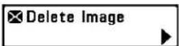
Delete Image
(optional-purchase SD Memory Card, Snapshot and Recording View only)
Settings: Press the RIGHT Cursor key and follow screen instructions.
Delete Image allows you to delete a single screen capture image. This option is only available when an optional-purchase SD card is installed, Snapshot and Recording View is on the screen, and you have selected image thumbnail.

Delete All Images
(optional-purchase SD Memory Card, Snapshot and Recording View only)
Settings: Press the RIGHT Cursor key and follow screen instructions.
Delete All Images allows you to delete all the images at once. This m option is only available when an optional-purchase SD memory card is installed and Snapshot and Recording View is on the screen.
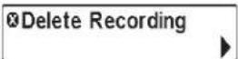
Delete Recording
(optional-purchase SD Memory Card, Snapshot and Recording View only)
Settings: Press the RIGHT Cursor key and follow screen instructions.
Delete Recording allows you to delete a single sonar recording. This m option is only available when an optional-purchase SD memory card is installed, Snapshot and Recording View is on the screen, and you have selected a recording file.

Delete All Recordings
(optional-purchase SD Memory Card, Snapshot and Recording View only)
Settings: Press the RIGHT Cursor key and follow screen instructions.
Delete All Recordings allows you to delete all the recordings at once. 1 menu option is only available when an optional-purchase SD memory car installed and Snapshot and Recording View is on the screen.

Pings Per Second
(optional-purchase SD Memory Card, Snapshot and Recording View only)
Settings: 1 to 10, Auto, Default = Auto
Pings Per Second allows you to specify the ping rate for an active son recording.
NOTE: Pings Per Second is available when an optional-purchase SD memory ca is installed, Snapshot and Recording View is on the screen, and the control he is actively recording (not playing back).
Auto is the default setting for Pings Per Second and automatically adjusts the ping rate for best recording quality. If there is limited memory on y memory card, you can slow the ping rate by setting the Pings Per Second manually, but the recording will capture less sonar detail. For maximum
performance, keep the Pings Per Second setting on Auto.

Playback Speed
(optional-purchase SD Memory Card, Snapshot and Recording View only)
Settings: Record, Rewind1, Rewind2, Slow Play Reverse, Pause, Slow Play, Normal Play, Fast Forward1, Fast Forward2, Stop
Playback Speed allows you to specify the playback speed for a sonar recording from the Snapshot and Recording View. This menu option is available when an optional-purchase SD card is installed and Recording Playback is active.
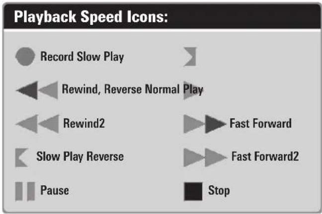
NOTE: You can also change playback speed in the Snapshot and Recording View using the LEFT and RIGHT Cursor keys, although you cannot skip to the beginning or end of a recording using these keys.
NOTE: Sonar chart speed is increased during Fast Forward and reversed during Rewind. This may result in a reduced quality sonar image, since at higher speed not every sonar return can be processed.
Stop Playback
Stop Playback
(optional-purchase SD Memory Card only)
Settings: Press the RIGHT Cursor key to activate.
only Stop Playback allows you to stop playback of a sonar recording from an view. This menu option is only available when an optional-purchase SD memory card is installed and Recording Playback is active.
NOTE: During playback, the amount of time/memory left to play is indicated b, the status bar. For more information, see Views: Snapshot and Recording View.
| Depth Alarm | Off |
| Fish ID Alarm | O |
| Low Battery Alarm | Off |
| Aux. Temp. Alarm | Off |
| Temp. Alarm | Off |
| Off Course Alarm | 328ft |
| Arrival Alarm | 164ft |
| Drift Alarm | Off |
| Alarm Tone | Medium |
| Timer Setup | |
| Start Timer | |
| Stop Timer |
Alarms Menu
Alarms Menu Tab
From any view, press the MENU key twice access the Main Menu. The Alarms tab will be the default selection.
NOTE: When an alarm is triggered, you can silence it by pressing any key. The alarm will be silenced, and will not be triggered again until a new instance of the alarm condition is detected.
| Depth Alarm | Off | |
| Off | 100 | |
Depth Alarm
Settings: Off, 1 to 100 feet, or 0.5 to 30 meters [International Models only]: Default = Off
Depth Alarm sounds when the depth becomes equal to or less than the menu setting.
| Fish ID Alarm |
| O |
Fish ID Alarm
Settings: Off, All, Large/Medium, Large; Default = Off
Fish ID Alarm sounds when the Fishfinder detects fish that correspond the alarm setting. Fish ID Alarm will only sound if Fish ID+TM is on.
For example, if you've set the Fish ID Alarm to sound for Large fish only, the Fish ID alarm will sound when a large-sized fish is detected.
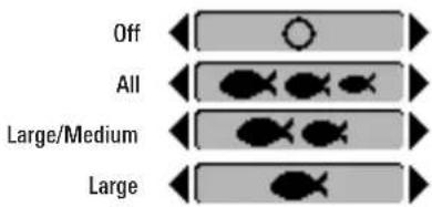
| Low Battery Alarm | Off |
| Off | 13.5 |
Low Battery Alarm
| Settings: Off, 8.5V - 13.5V; Default = Off |
Low Battery Alarm sounds when the input battery voltage is equal to than the menu setting. The battery alarm will only sound for the battery is connected to the Fishing System. The Low Battery Alarm should be slow to warn you when the battery voltage drops below the safety margin that have determined.
For example, if you are running a trolling motor (battery operated), you would want to set the Low Battery Alarm to sound before the battery voltage drops too low for it to be used to start your main, gasoline-powered engine.
| Temp. Alarm | Off |
| Off | 120 |
Temp. Alarm
| Settings: Off, 33-120 Fahrenheit, 0-50 Celsius [International Models only]: Default = Off |
Temp. Alarm sounds when the water temperature detected by the Fishir System reaches the Temp. Alarm setting, which is either set in degrees Fahrenheit or Celsius [International Models only].
For example, if the Temp. Alarm is set to 58 degrees Fahrenheit, and the wat temperature falls from 60 degrees to 58 degrees, the Temp. Alarm will sound. Similarly, if the water temperature rises from 56 degrees to 58 degrees, the Temp. Alarm will also sound.
| Aux. Temp. Alarm Off | Off | |
| Off | 120 | |
Aux. Temp Alarm
| (with optional-purchase Temp. probe or Temp/Speed only) |
| Settings: Off, 33-120 [Fahrenheit], 0-50 [Celsius], Default = Off |
Aux Temp Alarm sounds when the water temperature from the Paddlewheel/Temperature Probe detected by the Fishing System reaches the Aux Temp Alarm setting, which is set in degrees Fahrenheit or Celsius [International Models only].
For example, if the Aux Temp Alarm is set to 58 degrees Fahrenheit, and the water temperature falls from 60 degrees to 58 degrees, the Aux Temp Alarm will sound. Similarly, if the water temperature rises from 56 degrees to 58 degrees, the Temp Alarm will also sound.
| Off Course Alarm | 300ft |
| Off | 3000 |
Off Course Alarm
| Settings: Off, 25 to 3000 feet, 10 to 1000 meters [International Models only]; Default = 300 ft, 100 m |
Off Course Alarm allows you to set how far the boat is allowed to mc course before the Off Course Alarm will sound during navigation.
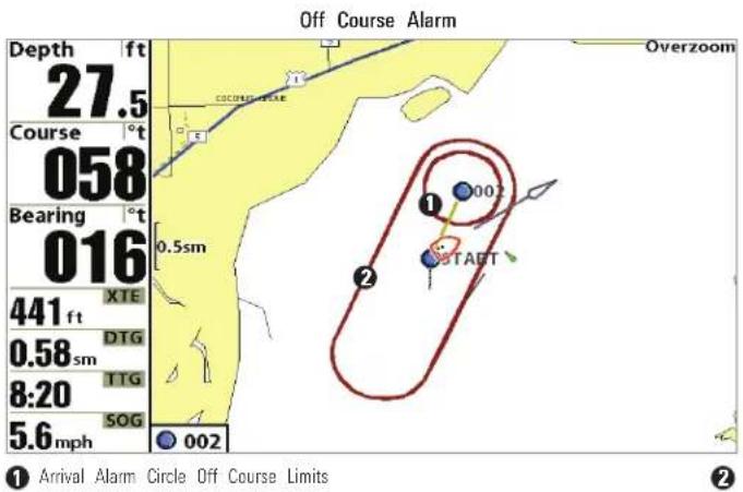
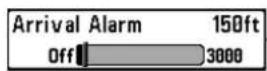
Arrival Alarm
Settings: Off, 25 to 3000 feet, 10 to 1000 meters [International Models only]; Default = 150 ft, 50 m
Arrival Alarm sounds when the boat has either exceeded the distance to destination waypoint, or has entered the Arrival Alarm Circle, based on the menu setting when navigating. Arrival Alarm allows you to set how close boat must be to the destination waypoint before the Arrival Alarm will sound.
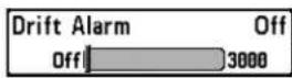
Drift Alarm
Settings: Off, 25 to 3000 feet, 10 to 1000 meters [International Models only]: Default = Off
Drift Alarm allows you to set the size of a perimeter around the boat's anchored position. If the anchored boat drifts outside of that perimeter, Drift Alarm will sound.
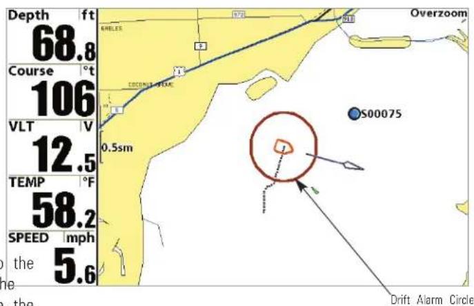
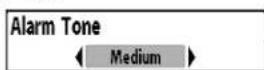
Alarm Tone
Settings: High, Medium, Low; Default = Medium
Alarm Tone selects the pitch of the alarm sound. A brief tone will be produced as you adjust the Alarm Tone so that you can select the tone you can hear best.
Timer Setup
Settings: Press the RIGHT Cursor key to open the dialog box.
Start Timer
Settings: Press the RIGHT Cursor key to start the Timer.
Timer Setup allows you to open a dialog box to create settings for the Start Timer allows you to start the Timer using the saved countdown Timer. You can also start the countdown from this dialog box. When the settings in the Timer Setup dialog box. To create the Timer settings, see Timer is started, the clock counts down from the amount of time set in the Timer Setup. dialog box.
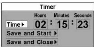
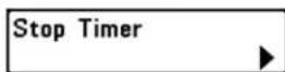
Stop Timer
(with the Timer running)
Settings: Press the RIGHT Cursor key to stop the Timer.
Stop Timer allows you to stop the Timer while it is counting down.
- Time: Use the 4-WAY Cursor Control key to set the hours, minutes, and seconds.
- Save and Start: To start the Timer immediately, select Save and Start, and press the RIGHT Cursor key.
- Save and Close: To save your settings and start the Timer at a later time, select Save and Close, and press the RIGHT Cursor key. Also, see Start Timer.
- Digital Readout: To display the Timer on-screen as it counts down, see Views: To Change the Digital Readouts.
| Beam Select | |
| 83kHz | |
| Imaging Frequency | |
| 455kHz | |
| Surface Clutter | |
| 5 | |
| SwitchFire | |
| Clear Mode | |
| Fish ID + | |
| Off | |
| Fish ID Sensitivity | |
| 5 | |
| RTS Window | |
| Narrow | |
| Sonar Colors | |
| Original Palette | |
| Bottom View | |
| Structure ID | |
| Zoom Width | |
| Narrow | |
| 83kHz Sensitivity | |
| 0 | |
| 455kHz Sensitivity | |
| 0 | |
| Depth Lines | |
| On | |
| SI Range Lines | |
| Off | |
| SI Readouts | |
| On | |
| Noise Filter | |
| Off | |
| Max Depth | |
| Auto | |
| Water Type | |
| Fresh | |
| Connected Transducer | |
| Hi-Def Sidescan | |
| Color Bar | |
| On | |
| Temperature Graph | |
| Off | |
| Down Imaging Beam Width | |
| Wide | |
| DI Colors | |
| Blue | |
Sonar Menu Tab
Press the MENU key twice to access the Main Menu and then press the RIGHT Cursor key until the Sonar tab is selected.
NOTE: Menu options can be expanded or simplified by setting the User Mode to Advanced or Normal. See Main Menu: User Mode for details.
NOTE: Menu options are determined by your Humminbird® model. See the following pages for full menu descriptions.
NOTE: The selected transducer also influences the menu options. See Sonar Menu Tab: Connected Transducer for more information.
999ci HD SI Sonar Menu (Advanced)
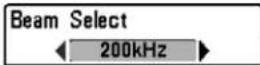
Beam Select
Settings: Various, see below.
Beam Select sets which sonar returns from the transducer will be displayed on the screen. The available beam frequencies are determined by your Humminbird® model.
DualBeam PLUS™ models (859ci HD, 959ci HD) and Side Imaging® models (899ci HD SI, 999ci HD SI) allow you to choose 200/83 kHz, 200 kHz, or 83 kHz (Default = 200/83 kHz).
- When set to 200/83 kHz, the returns from both beams are blended by starting with the 83 kHz wide beam return, dimming it, and then overlaying it with the 200 kHz narrow beam return. The darker 200 kHz narrow beam sonar returns will stand out from the paler 83 kHz wide beam sonar returns. The Split Sonar View continues to display the sonar returns from each beam in their respective windows. The blended information is shown in the Sonar View and the Sonar Zoom View. The RTS Window™ in the Sonar View will only show the returns from the 200 kHz narrow beam.
- When set to 200 kHz, only the returns from the 200 kHz narrow beam will be displayed in the Sonar View and the Sonar Zoom View. The Split Sonar View will continue to display returns from both beams in their respective windows. The RTS Window™ in the Sonar View will display the returns from the 200 kHz narrow beam.
- When set to 83 kHz, the returns from the 83 kHz wide beam will be displayed in the Sonar View and the Sonar Zoom View. The Split Sonar View will continue to display returns from both beams in their respective windows. The RTS Window™ will display the returns from the 83 kHz wide beam.
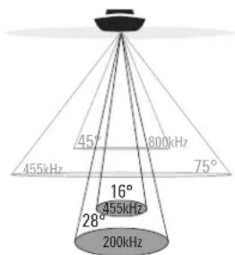
75 Degree Total Coverage
Bottom Coverage = 1 x Depth
The Down Imaging ^® models (859ci HD DI, 959ci HD DI) allow you to choose 200 kHz or 455 kHz for conical sonar coverage in the traditional sonar views.
- When set to 200 kHz, only the returns from the 200 kHz (28°) beam will be displayed.
-
When set to 455 kHz, only the returns from the 455 kHz (16°) narrow beam will be displayed.
-
When set to 200 kHz, only the returns from the 200 kHz narrow b or will be displayed in the Sonar View and the Sonar Zoom View. The Sonar View will continue to display returns from both beams in their respective windows. The RTS Window™ in the Sonar View will displ the returns from the 200 kHz narrow beam.
- When set to 50 kHz, the returns from the 50 kHz wide beam will displayed in the Sonar View and the Sonar Zoom View. The Split S View will continue to display returns from both beams in their respective windows. The RTS Window™ will display the returns from the 50 kHz wide beam.
The Xtreme Depth models (859ci HD XD, 959ci HD XD) allow you to choose 200/50 kHz, 200 kHz, or 50 kHz (Default = 200/50 kHz).
- When set to 200/50 kHz, the returns from both beams are blended by starting with the 50 kHz wide beam return, dimming it, and then overlaying it with the 200 kHz narrow beam return. The darker 200 kHz narrow beam sonar returns will stand out from the paler 50 kHz wide beam sonar returns. The Split Sonar View continues to display the sonar returns from each beam in their respective windows. The blended information is shown in the Sonar View and Sonar Zoom View. The RTS Window™ in the Sonar View will only show the returns from the 200 kHz narrow beam.

Imaging Frequency
(859ci HD DI, 959ci HD DI, 899ci HD SI and 999ci HD SI only)
Settings: Various, see below.
Imaging Frequency allows you to select which frequency to apply to the down Imaging® and Side Imaging® beams. For the best overall image quality and depth, select 455 kHz. For the sharpest image (but limited depth capability), select 800 kHz.
Down Imaging® Beams
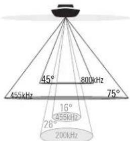
75 Degree Total Coverage
Bottom Coverage = 1 x Depth
• 859ci HD DI: 800 kHz, 455 kHz; Default = 455 kHz
• 959ci HD DI: 800 kHz, 455 kHz; Default = 455 kHz
• 899ci HD SI: 455 kHz; Default = 455 kHz
• 999ci HD SI: 800 kHz, 455 kHz; Default = 455 kHz
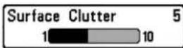
Surface Clutter
Settings: Low = 1 to High = 10; Default = 5
Surface Clutter adjusts the filter that removes surface clutter noise caused by algae and aeration. The lower the setting, the less surface clutter will be displayed.
heatmap
| Depth (ft) | Value | |------------|-------| | 45.7 | 12.5 | | 51:07 | 65.1 | | 51:07 | 3.4 |
| SwitchFire® |
| Settings: Clear Mode, Max Mode; Default = Clear Mode |
SwitchFire® controls how the sonar returns are displayed in the Sonar View
Choose Max Mode to see only raw sonar returns on the display. When M Mode is selected, you will see the maximum sonar information available with the transducer beam, so more fish arches and better jig tracking are shown
Choose Clear Mode to see less clutter and more fish size accuracy on the display. When Clear Mode is selected, the clutter is filtered, and sonar returns are interpreted to provide more details about the objects within the transducer beam, regardless of their location. In other words, a large arch of the display means a large fish has been detected.
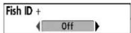
Fish ID+TM
Settings: Off, On; Default = Off
Fish ID+™ uses advanced signal processing to interpret sonar returns and will display a Fish Symbol when very selective requirements are met. When of the fish is detected, a fish icon and its depth are displayed above the return that has been classified as being a fish. Three different fish size icons represent the intensity of the sonar return and provide an indicator of relative fish size.
In DualBeam PLUSTM models (859ci HD, 959ci HD, 899ci HD SI, and 999ci HD SI), targets detected in the 200 kHz narrow beam are represented as orange fish symbols, and targets detected in the 83 kHz wide beam are represented as blue fish symbols.

Narrow beam
Orange Fish Symbols

Wide beam
Blue Fish Symbols
In Down Imaging ^® models (859ci HD DI and 959ci HD DI), targets detected in the 455 kHz conical beam are represented as blue fish symbols, and detected in the 200 kHz conical beam are represented as orange fish s
In the Xtreme Depth models (859ci HD XD and 959ci HD XD), targets detected in the 200 kHz narrow beam are represented as orange fish symbols and targets detected in the 50 kHz wide beam are represented by blue fish symbols.
When Fish ID+TM is turned off, the Fishfinder shows only the raw sonar returns as fish. returns on the display. These returns will often result in "arches" forming on
the display, indicating potential targets. Due to the transducer beam and the distance to a fish decreases as the fish moves into the beam, and increases as it moves out again, creating a Fish Arch when this distance change is shown on the display. Boat speed, chart speed, and the posit of the fish within the sonar beam greatly affect the shape of the arch.
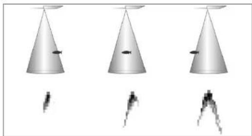
natural_image
Three identical conical objects with internal dark shapes suspended from them, shown in different angles (no text or symbols)Transducer Cone and Fish Arches

Fish ID Sensitivity adjusts the threshold of the Fish ID+™ detection targets algorithms. Selecting a higher setting allows weaker returns to be displayed as fish. This is useful for identifying smaller fish species or baitfish. Select a lower setting displays fewer fish from weak sonar returns. This is helped when seeking larger species of fish.
as Fish ID Sensitivity is used in conjunction with Fish ID + ^TM . Fish ID + ^TM mu On for Fish ID Sensitivity to affect the ability of the Fishfinder to identil
| RTS Window |
| ← Narrow → |
Real Time Sonar (RTS™) Window
Settings: Wide, Narrow, Off; Default = Narrow
RTS Window™ sets the RTS Window™ to Wide or Narrow, or turns it the Sonar Views. The RTS Window™ always updates at the fastest rate possible and only displays returns that are within the transducer beam. What's on the Sonar Display for more information.
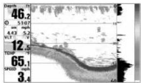
RTS Window™ (Wide)
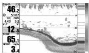
line
| Depth (mm) | Value | | ---------- | ----- | | 46.2 | 46.2 | | 51.07 | 51.07 | | 4.43 | 4.43 | | 5.2 | 5.2 | | 12.5 | 12.5 | | 65.1 | 65.1 | | 3.4 | 3.4 |RTS Window™ (Narrow)
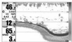
RTS Window™ (Off)
NOTE: The Wide RTS Window™ does not use grayscale.
| Sonar Colors |
| Original Palette |
Sonar Colors
Settings: Gray, Green, Inverse, Original Palette, Palette 1, Palette 2, Palette 3; Default = Original
Sonar Colors allows you to select which color palette you would like to for the display. The palette you choose will be applied to the Sonar Vie
- Gray: Light Gray (weak) to Black (strong)
- Green: Dark Green (weak) to Light Green (strong)
• Inverse: Black (weak) to White (strong)
• Original Palette: Cyan (weak) to Red (strong) - Palette 1: Navy Blue (weak), Purple (medium), Yellow (strong)
- Palette 2: Navy Blue (weak), Green (medium), Yellow (strong)
- Palette 3: Navy Blue (weak) to Red (strong)
| Bottom View |
| Structure ID |
Bottom View
Settings: Structure ID, WhiteLine; Default = Structure ID
Bottom View selects the method used to represent bottom and structure the display.
- Structure ID™ represents weak returns in blue and strong returns i red. If the Sonar Colors palette is changed, the Structure ID™ will display the strongest return as specified by the palette.
- WhiteLine™ highlights the strongest sonar returns in white, resulting in a distinctive outline. This has the benefit of clearly defining the bottom on the display.
See What's on the Sonar Display: Sonar Colors and Bottom View information.

Zoom Width
(Sonar Zoom View only)
Settings: Narrow, Medium, Wide; Default = Wide
Zoom Width adjusts the width of the zoomed view on the Sonar Zoom View.
See Views: Sonar Zoom View for more information.
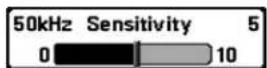
50 kHz Sensitivity
(Advanced, XD Sonar only [859ci HD XD, 959ci
Settings: -10 to +10; Default = 0
50 kHz Sensitivity changes the sensitivity of the 50 kHz beam. Increasing the 50 kHz Sensitivity will display additional weak returns, and decreasing the 50 kHz Sensitivity will display fewer weak returns.
NOTE: 50 kHz Sensitivity is particularly useful for adjusting the sensitivity of the 50 kHz sonar returns in the 200/50 kHz Split Sonar View. The 50 kHz sensitivity can be adjusted without affecting the sensitivity of the 200 kHz returns shown s the 200 kHz sonar window
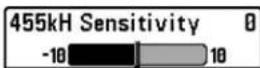
455 kHz Sensitivity
(Advanced, Down Imaging® Views only [859ci HD DI and 959ci HD DI])
Settings: -10 to +10, Default = 0
455 kHz Sensitivity adjusts the sensitivity of the 455 kHz beam. Increase sensitivity to display additional weak returns and decrease the sensitivity display fewer weak returns. HD XDJ)
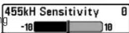
455 kHz Sensitivity
(Advanced, with optional-purchase QuadraBeam PLUS™ transducer)
Settings: -10 to +10, Default = 0
455 kHz Sensitivity adjusts the sensitivity of the 455 kHz beam. Increase sensitivity to display additional weak returns and decrease the sensitivity display fewer weak returns.
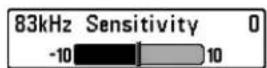
83 kHz Sensitivity
(Advanced, DualBeam PLUS™ Sonar only
[859ci HD, 959ci HD, 899ci HD SI, 999ci HD
Settings: -10 to +10, Default = 0
NOTE: 455 kHz Sensitivity is particularly useful for adjusting the sensitivity of the 455 kHz sonar returns in the Side Beam View. The 455 kHz sensitivity ca SI) be adjusted without affecting the sensitivity of the 200 kHz returns shown in the 200 kHz sonar window.
83 kHz Sensitivity changes the sensitivity of the 83 kHz beam. Increasing the 83 kHz Sensitivity will display additional weak returns, and decreasing the 83 kHz Sensitivity will display fewer weak returns.
NOTE: 83 kHz Sensitivity is particularly useful for adjusting the sensitivity of the 83 kHz sonar returns in the 200/83kHz Split Sonar View. The 83 kHz sensitivity can be adjusted without affecting the sensitivity of the 200 kHz returns shown in the 200 kHz sonar window.
The 455 kHz Sensitivity menu option is available when a QuadraBeam PLUS™ transducer is attached to the Fishing System, User Mode is set Advanced (see Setup Menu Tab: User Mode), and Connected Transdu set to QuadraBeam (see Sonar Menu Tab: Connected Transducer).
NOTE: Visit our Web site at humminbird.com to order this accessory online or contact our Customer Resource Center at 1-800-633-1468.
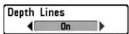
Depth Lines
(Advanced)
Settings: Off, On; Default = On
Depth Lines divide the display into four equal sections which are separated by three horizontal depth lines. The depth of each line is displayed along the depth scale. You can turn Depth Lines On or Off.

heatmap
| Depth (ft) | Value | |---|---| | 45.7 | 0 | | 51:07 | 13 | | 51:07 | 13 | | 51:07 | 13 | | 51:07 | 13 | | 51:07 | 13 | | 51:07 | 13 | | 51:07 | 13 | | 51:07 | 13 | | 51:07 | 13 | | 4.43 | 30 | | 4.43 | 30 | | 4.43 | 30 | | 4.43 | 30 | | 4.43 | 30 | | 4.43 | 30 | | 4.43 | 30 | | 4.43 | 30 | | 4.43 | 30 | | 4.43 | 30 |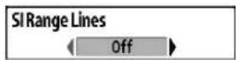
SI Range Lines
(Advanced, Side Imaging ^® View only [899ci HD SI and 999ci HD SI])
Settings: On, Off; Default = Off
SI Range Lines divide each side beam range into four equal sections on the display. SI Range Lines can be used to interpret the location of objects on the display. You can turn SI Range Lines On (visible) or Off (hidden).
NOTE: The range numbers are estimated and should not be used for measurement.
NOTE: If both SI Range Lines and Contour Mode are turned on, the SI Range Lines will remain on the display, but the individual range numbers are not available (see Side Imaging® X-Press™ Menu: SI Enhance).
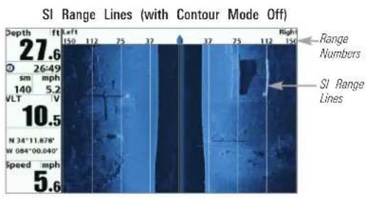
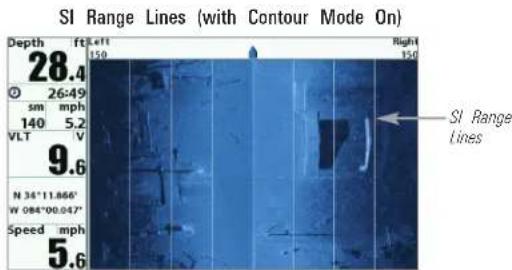
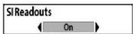
SI Readouts
(Advanced, Side Imaging® View only [899ci HD and 999ci HD SI])
Settings: On, Off; Default = On
SI Readouts allows you to display or hide the digital readout boxes in Side Imaging® View.
When SI Readouts is set to Off, Temperature and Depth will continue displayed on the screen.
NOTE: See Setup Menu Tab: Select Readouts for more information.
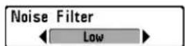
Noise Filter
(Advanced)
Settings: Off, Low, Medium, High 1, High 2, High 3; Default = Low
Noise Filter adjusts the sonar Noise Filter to limit interference on the disp from sources such as your boat engine, turbulence, or other sonar devices
The Off setting removes all filtering. Low, Medium, and High 1, High 2, H 3 settings add progressive filtering of the sonar returns. High 1, High 2,
High 3 are useful when there is excessive trolling motor noise, but in some deep water situations, the High settings may actually hinder your unit's ability to find the bottom.
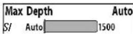
Max Depth
(Advanced)
Settings: Various, see below.
Max Depth controls the maximum depth of operation. When Max Depth not to Auto, the Fishing System will acquire bottom readings as needed (within the capacity of the unit). When Max Depth is set to match your fishing maximum depth, your Fishing System will not attempt to acquire some data below that depth, so more detail will be shown on the scre
NOTE: If the bottom is deeper than the Max Depth setting, the digital depth readout will flash, indicating that the Fishfinder cannot locate the bottom.
- 859ci HD/959ci HD: Auto to 1500 ft, Auto to 500 m (International Models only); Default = Auto
- 859ci HD DI/959ci HD DI: Auto to 1500 ft, Auto to 500 m (International Models only); Default = Auto
- 899ci HD SI/999ci HD SI: Auto to 1500 ft, Auto to 500 m play{International Models only}; Default = Auto
• 859ci HD XD/959ci HD XD: Auto to 3280 ft, Auto to 1000 m
high(International Models only); Default = Auto
eMax Depth controls the down beam reading. The SI Range (Side Imaging® Range) controls the side beams and down beam reading at the same time. If SI Range is set to a deeper range than the Max Depth setting, your 899ci HD SI Combo or 999ci HD SI Combo will default to the SI Range setting. For example, if you set the Max Depth to 50 feet and then set the SI Range to 150 feet, your unit will acquire bottom readings from 150 feet (see Side Imaging® X-Press™ Menu: SI Range).
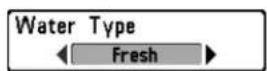
Water Type
(Advanced)
Settings: Fresh, Salt (shallow), Salt (deep);
Default = Fresh
Water Type configures your unit for operation in fresh or salt water. In water, you can also choose the shallow or deep setting. The Water Type menu option is available when User Mode is set to Advanced (see Main Menu: User Mode).
NOTE: Make sure that the Water Type is set accurately, especially in salt water as this affects the accuracy of deep water depth readings. In salt water, what would be considered a large fish might be 2 to 10 times bigger than a large in fresh water (depending on the type of fish you are seeking). The salt water setting allows for a greater range in fish size adjustment to account for this difference.

Digital Depth Source
(Advanced, Down Imaging ^® models with optional-purchase transducers only [859ci HD
DI and 959ci HD DI)
Settings: Auto, 2D Element; Default = Auto
Digital Depth Source specifies the beams that will be used to provide the depth for the digital depth readouts (see Views and Setup Menu Tab: Select Readouts for more information). It is important to set this menu option based on the transducer that is connected to the control head, as follows:
- If a Down Imaging ^ transducer is connected to the control head, select Auto. Depending on the depth, Auto will automatically choose the 2D conical beams or the Down Imaging ^ beams to display dept in the digital readout window. Auto is the default setting.
- If an accessory transducer is connected to the control head, select 2D Element. For example, if you connect an ice transducer to your Down Imaging® unit, change the digital depth source to 2D Element in order to display depth in the digital readout window. The 2D Element setting should not be used with a Down Imaging® transducer.
NOTE: Visit our Web site at humminbird.com to determine which accessory transducers are compatible with your Humminbird® Fishing System, or Contact our Customer Resource Center.
NOTE: When Digital Depth Source is set to 2D Element, the DI setting will be removed from the DI Pings menu. When DI Pings is set to DI, the 2D Element setting will be removed from the Digital Depth Source menu. See DI Pings for more information.
Connected Transducer ◀ Compact Sidescan ▶
Connected Transducer
Settings: Hi-Def Sidescan, Compact Sidescan, Sidescan, DI 200/455, DI 200/83, DI 200/50, Quad Beam, Dual Beam, Dual 50/200, Universal Sonar 2; Default = Various, see below
Connected Transducer allows you to choose which connected transducer you want to use. When you choose a transducer, the corresponding features will be automatically added to your Fishing System.
NOTE: This feature may appear as either Connected Transducer or Transducer Select, depending on your model.
- 859ci HD and 959ci HD: Dual Beam is the default selection. The QuadraBeam PLUS™, Dual 50/200 kHz and Universal Sonar 2 transducers require a separate purchase. The 859ci HD/959ci HD does not support High-Definition Sidescan, Compact Sidescan, or Sidescan transducers.
- 859ci HD DI and 959ci HD DI: Down Imaging® is the default selecti The DI 200/50 kHz, Dual 50/200 kHz, Dual 83/200 kHz, and Universal Sonar 2 transducers require a separate purchase. The 859ci HD DI/959ci HD DI does not support High-Definition Sidescan, Compact Sidescan, or Sidescan transducers.
- 899ci HD SI: Compact Sidescan is the default selection. Hi-Def Sidescan, Sidescan, Down Imaging®, QuadraBeam PLUS™, Dual Beam, Dual 50/200, and Universal 2 require a separate purchase.
-999ci HD SI: Hi-Def Sidescan is the default selection. The Compact Sidescan, Sidescan, Down Imaging®, QuadraBeam PLUS™, Dual Beam, Dual 50/200, and Universal Sonar 2 require a separate purchase.
- 859ci HD XD and 959ci HD XD: Your Fishing System will default to Dual 200/50. Your Fishing System also supports the optional-purchase DualBeam PLUS™ transducer (XNT 9 20) and optional-purchase Universal Sonar 2.
NOTE: To purchase transducers, visit our Web site at humminbird.com or call our Customer Resource Center at 1-800-633-1468.
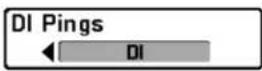
DI Pings
(Advanced, Down Imaging® View and Chart/Down Combo View only)
Settings: 2D + DI, DI; Default = 2D + DI
DI Pings allows you to select which beams will be used to display returns the Down Imaging ^® view.
Select 2D + DI to display returns from both the 2D sonar beams and the Down Imaging® beams.
Select DI to display returns from the Down Imaging ^® beams only. Selecting DI provides faster screen updates.
NOTE: When DI Pings is set to DI, the 2D Element setting will be removed from the Digital Depth Source menu. When the Digital Depth Source is set to 2D Element, the DI setting will be removed from the DI Pings menu. See Digital Depth Source for more information.
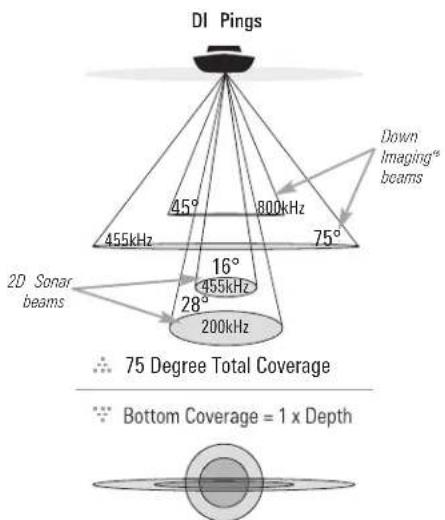
NOTE: See How Sonar Works: Down Imaging® Sonar for more information
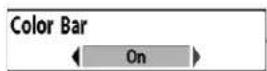
Color Bar
Settings: Off, On, Default = On
Color Bar allows you to display or suppress the display of the color bar shown in the full screen Sonar View.
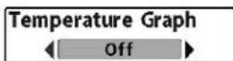
Temperature Graph
(Sonar View only, with Temperature input)
Settings: Off, On, Default = On
Temperature Graph allows you to display or suppress a water temperature graph over the main Sonar View to show temperature changes correlated recent sonar history.
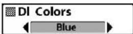
DI Colors
(859ci HD DI, 959ci HD DI, 899ci HD SI, and HD SI only)
Settings: Blue, Amber 1, Amber 2, Brown, Green, Inverse, Gray, Green/Red; Default = Amber 1
DI Colors allows you to select which color palette you would like to us the Down Imaging® display.
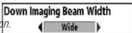
Down Imaging® Beam Width
(Advanced, 899ci HD SI and 999ci HD SI only)
Settings: Narrow, Medium, Wide; Default = Wide
Down Imaging ^® Beam Width controls the width of the beam (side to s for the Down Imaging ^® View and sets the amount of information shown the display.
To see only the data directly under your boat, select Narrow. Medium no more information, while Wide displays the maximum information available from the Down Imaging® beam width.
| Current Track | |
| Waypoints, Routes, Tracks | |
| Waypoint Settings | |
| Saved Tracks Defaults | |
| Chart OrientationNorth-Up | |
| Casting RingsOff | |
| North ReferenceTrue | |
| Waypoint Proximity FlagsOff | |
| Waypoint DeclutteringOff | |
| Trolling Grid Rotation0° | |
| Trackpoint Interval15 seconds | |
| Track Min Distance50ft | |
| Track Color Range50ft | |
| Map DatumWGS 84 (Default) | |
| North Up IndicatorOff | |
| Course Projection LineStandard | |
| 3D View OutlineVisible | |
| Continuous Navigation ModeOff | |
| SI NavigationOff |
Navigation Menu Tab
Press the MENU key twice to access the Main Menu, then press the RIGHT Cursor key until the Navigation tab is selected.
NOTE: Menu options will vary depending on system settings, such as whether you are currently navigating.
NOTE: Menu options can be expanded or simplified by setting the User Mode to Advanced or Normal. See Main Menu: User Mode for details.
NOTE: Menu options are determined by your Humminbird® model. See the following pages for full menu descriptions.
899ci HD SI, 999ci HD SI Navigation Menu Tab, Advanced
| Current Track | Save | Current Track |
| Clear | Settings: Save, Clear, Appearance, Stop Tracking | |
| Appearance | ||
| Stop Tracking |
Current Track allows you to view the Current Track submenu. See Introduction to Navigation: Tracks for more information.
The Current Track Submenu contains the following menu options:
Save allows you to save the current track.
Clear allows you to delete the current track.
Appearance allows you to change the style and color of the current track. (Breadcrumb Trail, Dashed Line, Solid Line or Wide Line, and a line, the color of the line, or Color By Depth).
- If you choose Color By Depth, you cannot choose one color to represent the track. A color range will represent the different depths on the track instead, from light green (shallowest) to black (deepest). You can change the depth range associated with black by using the Track Color Range menu setting (see Navigation Menu Tab: Track Color Range).
- If you choose Hidden, the unit continues to save trackpoints, but the track will not be displayed on the view.
Stop Tracking clears the current track and the unit will not save trackpoints. To resume saving the track, select Current Track > Start Tracking.
NOTE: To save the depth information with the Current Track, it is important save the track and also edit the name before powering off the control head.
Waypoints, Routes, Tracks
Waypoints, Routes, Tracks
(Waypoint Management Dialog Box)
Settings: Press the RIGHT Cursor key to open the dialog box.
Waypoints, Routes, Tracks allows you to open the Waypoint Management dialog box. Use the Waypoint Management dialog box to create new waypoints and routes and organize your navigation data. You can also edit waypoint, route, and track information. Your navigation data can be saved into groups, sorted, copied, and exported to HumminbirdPC™.
See Introduction to Navigation and the Humminbird® Waypoint Management Guide for more information.
Waypoint Settings
Waypoint Settings
Settings: Press the RIGHT Cursor key to open the dialog box.
Waypoint Settings allows you to open the Waypoint Settings dialog box. Use the Waypoint Settings dialog box to set the waypoint icon category and the waypoint icon for all new waypoints. See Introduction to Navigation: Edit your Waypoints, Routes, Tracks, and Groups and the Humminbird® Waypoint Management Guide for details.
The Waypoint Settings dialog box includes the following options
Icon Category allows you to select a waypoint icon category (All, Geometry, Alerts, Supplies, Navigation, Recreation, Fish, Environment). The Default Waypoint Icon also changes to match the selected category.
Default Waypoint Icon allows you select an icon for all new waypoints. To see the most icon choices, set the Icon Category to
New Waypoint Icon:
Select Default, and the system will automatically apply your settings to new waypoints.
If you choose Select, each time you mark a waypoint (by pressing the MARK key), you will be prompted to change the waypoint icon and category. To accept the current settings, press the MARK key again.
Saved Tracks Defaults
Saved Tracks Defaults
Settings: Press the RIGHT Cursor key to open the dialog box.
Saved Tracks Defaults allows you to open the Default Track dialog box. the dialog box to set the default track appearance for all newly-saved tr
The Saved Tracks dialog box includes the following options:
Visibility allows you to set new tracks to visible or hidden.
Style allows you to set the appearance and color of new tracks (Breadcrumbs Trail, Dashed Line, Solid Line or Wide Line, and if a line is the color of the line, or Color By Depth).
If you choose Color By Depth, you cannot choose one color to represent the track. A color range will represent the different depths on the track instead, from light green (shallowest) to black (deepest). You can change the depth range associated with black by using the Track Color Range menu setting (see Navigation Menu Tab: Track Color Range).
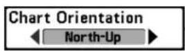
Chart Orientation
Settings: North-Up, Heading Up, Course-Up; Default = North-Up
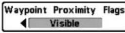
Waypoint Proximity Flags
(Advanced)
Settings: Hidden, Visible; Default = Hidden
Chart Orientation allows you to select whether the Chart and Combo Views should be drawn North-Up, Heading Up, or Course-Up. The Chart Orientation setting does not apply to the Bird's Eye View (see Viewing Cartography). Waypoint Proximity Flags allows you to display or hide waypoint flags in the ten closest waypoints to the boat or active cursor. The flags show distance from the boat (or active cursor) to each waypoint.
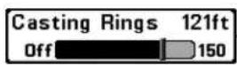
Casting Rings
Settings: Off to 150 feet, 0 to 50 meters; Default Off
Waypoint Proximity Flags are also influenced by the zoom level and boat speed. The flags are only displayed if the chart range is less than .5 s or the boat is traveling less than 15 mph.
Casting Rings allows you to display a circle around each waypoint on the Chart View. This menu option sets the distance that the Casting Ring will be displayed from the waypoint. Select Off to hide the Casting Rings.
NOTE: Casting Rings are not applied to decluttered waypoints (see Navigation Menu Tab: Waypoint Decluttering).

North Reference
Settings: True, Magnetic; Default = True
North Reference allows you to have bearings displayed with one of two orientations: True North or Magnetic North.
Chart View with Waypoint Flags Turned On
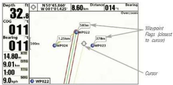
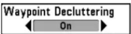
Waypoint Decluttering
(Advanced)
Settings: Off, On; Default = On
Waypoint Decluttering allows you to set the declutter feature On or Off. When two or more waypoints overlap, or are displayed close together on chart view, the screen will automatically declutter—waypoint names will shorten and the waypoint icons will change into small blue icons. Select to display waypoints at regular size.
Trackpoint Interval works in conjunction with Track Min Distance. Both conditions must be met before a trackpoint is added to the current track during slow travel or drift, setting both Trackpoint Interval and Track Min Distance to small values will allow you to increase the track resolution.
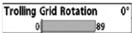
Trolling Grid Rotation
Settings: 0° to 89°, Default = 0°
Trolling Grid Rotation allows you to set the orientation of the trolling degrees, where a setting of 0^ displays a standard North, South, East, alignment. See Introduction to Navigation: Add a Waypoint Target Trolling Grid for information.
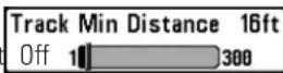
Track Min Distance
(Advanced)
Settings: 1 to 300 feet, or 1 to 100 meters [International Units only]; Default = 16 ft, 5 m
Track Min Distance allows you to set a minimum distance of travel bef trackpoint is added to the track.
Track in Min Distance works in conjunction with Trackpoint Interval. Both work conditions must be met before a trackpoint is added to the current track during slow travel or drift, setting both Trackpoint Interval and Track Min Distance to small values will allow you to increase the track resolution.
NOTE: This feature may appear as either Trolling Grid Rotation or Grid Rotation depending on your model.
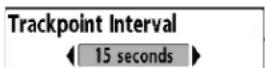
Trackpoint Interval
Settings: 1 second, 5 seconds, 10 seconds, 15 seconds, 30 seconds, or 60 seconds; Default = 1 second
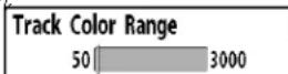
Track Color Range
Settings: 50 to 3000* feet or 20 to 1000 meters [International Units only], Default = 50 ft, 20 m
Track Color Range allows you to set the depth range that will be displayed as black, the deepest depth, when Color By Depth is selected as the st the current track (see Navigation Menu Tab: Current Track).
Trackpoint Interval allows you to select the time period between trackpoints. The current track can only contain up to 20,000 trackpoints, longer time periods cause the track to extend back further in time, but be less detailed.
*NOTE: Only an optional-purchase transducer with a 50 kHz frequency will allow you to track to 3000 feet.
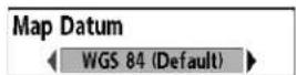
Map Datum
(Advanced)
Settings: Various, Default = WGS 84
Map Datum allows you to change the map coordinate system used by Fishing System to match those of a paper map.
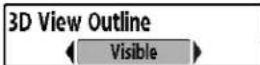
3D View Outline
Settings: Hidden, Visible, Default = Visible
3D View Outline allows you to display or hide an outline on the Chart the either Chart or Bird's Eye Combo Views that shows what you're view on the Bird's Eye side of the view.
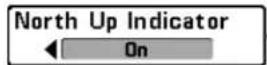
North-Up Indicator
Settings: On, Off; Default = Off
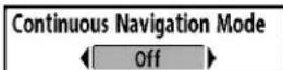
Continuous Navigation Mode
Settings: Off, On, Default = Off
North-Up allows you to display the North-Up icon on the screen to indicate Continuous Navigation Mode allows you to continue to navigate and fis the direction of True North. The icon also displays the Chart Orientation, and a particular waypoint, even if you pass over it multiple times. It will change as the orientation and the data source change. To set the
Chart Orientation, see Navigation Menu Tab. Also, see Views: View Orientation.

Course Projection Line
Settings: Hidden, Standard, Single Vector, COG/SOG; Default = Standard
Course Projection Line displays an arrow or line, extending from the boat, that projects your current course and shows where the boat if you continue on your present course.
You can choose the style of the Course Projection Line as follows:
- Standard = arrow
- Single Vector = line
- COG/SOG = line with tick marks at set intervals from the boat. The tick marks are based on the speed calculation.

SI Navigation
(Side Imaging ^® models only [899ci HD SI and 999ci HD SI])
Settings: Off, On, Default = On
SI Navigation controls how the boat icon is displayed in Side Imaging® Views. If SI Navigation is turned on, the boat icon indicates the direction of boat needs to turn to reach the next waypoint during navigation. The boat icon color will also change to orange.
If SI Navigation is turned Off, the boat icon will not change during nav although you can still mark waypoints and start navigation from a Side Imaging® View. See Side Imaging® View and Introduction to Navigation for more information.
| Lat/Lon Grid | Hidden |
| Navalds on Bird's Eye View | Visible |
| Chart Select | Auto |
| Set Simulation Position | |
| Set Map Offset | |
| Clear Map Offset | |
| Shaded Depth | 5ft |
| Chart Detail Level | All |
| Map Borders | MMC/SD Only |
| Spot Soundings | Hidden |
| Auto Zoom | Off |
| Auto Range | Off |
| Vessel Offset | Off |
| Offset Speed | 5mph |
| Contour Lines | Visible |
| Depth Colors | Shaded |
| Depth Highlight | Off |
| Depth Highlight Range | 5ft |
| Water Level Offset | 0 |
| Shallow Water Highlight | 0 |
| Lake List |
Chart Menu Tab
Press the MENU key twice to access the Main Menu and then press the RIGHT C key until the Chart tab is selected.
NOTE: Menu options can be expanded or simplified by setting the User Mode to Advanced or Normal. See Main Menu: User Mode for details.
NOTE: When a map from an optional purchase SD card is installed, the Chart Menu Tab will change to display menu options that correspond with the active chart. To manually select a chart card, see Chart Select. Also, see Add Maps to the Fishing System for more information.
Chart Menu (Advanced, shown with optional-purchase Navionics ^® and LakeMaster ^® menu options)
| Lat/Lon Grid |
| Hidden |
Lat/Lon Grid
Settings: Hidden, Visible, Default = Hidden
pLat/Lon Grid allows you to display or hide a grid showing latitude and longitude lines.
| Navaids on Bird's Eye ViewVisible |
Navaids on Bird's Eye View
Settings: Hidden, Visible, Default = Visible
Navaids on Bird's Eye View allows you to display or hide additional navigational aids in Bird's Eye View, such as lights and buoys.
NOTE: You will see more navigational aids with an optional-purchase SD card.
| Chart Select |
| Auto |
Chart Select
Settings: Auto, Contour XD, Left Chart Card, Right Chart Card; Default = Auto
Chart Select allows you to choose which chart to use if you have built charts or a map card. If you select Auto, your unit will select a chart automatically. Select Right to use the SD card installed in the right card and select Left to use the SD card installed in the left card slot (see S Memory Card Slots: Add Maps to Your Fishing System).
NOTE: The SD Memory Cards require a separate purchase. For more information visit our Web site at humminbird.com or contact our Customer Resource Center at 1-800-633-1468.
Set Simulation Position ▶ Settings: Press the RIGHT Cursor key and follow screen instructions to activate.
Set Simulation Position allows you to set the position of the boat used the Simulator. Press any arrow on the 4-WAY Cursor Control key to act the cursor and move it to the coordinates where you want to start the simulation. Then confirm the position using the Set Simulation menu sett
NOTE: The cursor must be active in order for this procedure to work. If the cursor was not active before you began this procedure, an error message will appear. Exit the menu, set the cursor, then try again.
Set Map Offset ▶ Settings: Press the RIGHT Cursor key and follow screen instructions to activate.
Set Map Offset allows you to change the map offset used by your Fis Press the 4-WAY Cursor Control key to activate the cursor and move it location where the Map Offset will be applied. Then, confirm the map position using the Set Map Offset menu setting.
The Map Offset will be applied to all maps and not just the map that requires the correction. The Map Offset should be cleared if a different map is to be used.
NOTE: The cursor must be active in order for this procedure to work. If the cursor was not active before you began this procedure, an error message will appear. Exit the menu, set the cursor, then try again.
NOTE: This feature does not apply to LakeMaster® charts.
Clear Map Offset Clear Map Offset(Advanced) Settings: Follow screen instructions to activate.
Clear Map Offset allows you to clear the Map Offset. The Clear Map C menu option is available when Map Offset is active.
Shaded Depth 16ft Off 180 Settings: Off, 1 to 180 feet, or 1 to 60 meters [International Units only], Default = 15 ft, 5 m
Shaded Depth allows you to change the depth used for shading on the Chart Views.
Chart Detail Level All Chart Detail Level Settings: Basic, Navigation, Underwater, All,
Chart the Detail Level allows you to select how much chart detail you want displayed on the Navigation Views.
NOTE: Some chart details are only available with optional-purchase SD cards.
Basic shows land areas, ports, obstructions, and restricted areas.
Navigation shows navaids, landmarks, ferryways, and navigation routes in addition to the Basic information.
Underwater shows depth contours, fishing areas, underwater wrecks, tides and currents in addition to the Basic and Navigation information.
All shows roads, buildings, railways, and other notations in addition to the Basic, Navigation, and Underwater information.
Custom (Advanced user mode) allows you to display or hide chart layers on the Navigation Views. The available chart layers include Navigable Canals, Boundaries, Restricted Areas, Coastline, Bridges, etc.
To customize the chart layers:
- Select Chart Detail Level from the Chart Menu Tab. Press the RIGHT Cursor key to select Custom. Selecting Custom adds the Custom Chart Layers menu to the Chart menu.
- Press the DOWN Cursor key to select Custom Chart Layers, and press the RIGHT Cursor key to access the submenu.
- Use the 4-WAY Cursor key to select a layer and turn it on (visible) or off (hidden). All changes take place immediately.
Map Borders, shown with optional-purchase Navionics® Cartography with Custom Chart Layers
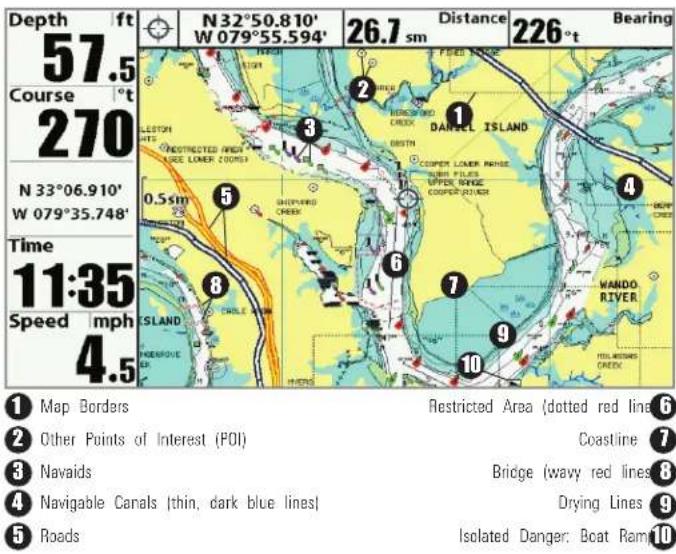
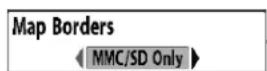
Map Borders
Settings: Hidden, MMC/SD Only, All Visible; Default = MMC/SD Only
Map Borders allows you to display or hide map borders. The dotted line a Map Border indicate an area which contains a different map. Use the 4-WAY Cursor key to move the active cursor within a map border, and the ZOOM + key to view the different map.
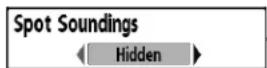
Spot Soundings
Settings: Hidden, Visible, Default = Hidden
Spot Soundings allows you to display or hide spot soundings, which are depth measurements shown on the chart.
NOTE: Spot Soundings are only available with optional-purchase SD cards.
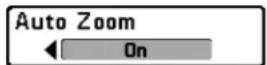
Auto Zoom
(Advanced)
Settings: On, Off; Default = Off
Auto Zoom sets the Chart View to zoom automatically based on the speed of the boat. As the boat's speed increases, the chart range will increase can continue to use the +/- ZOOM keys to see more or less of the view. Auto Zoom will resume after 20 seconds. To use only the +/- ZOOM keys adjust the chart range, turn off Auto Zoom. See Views: Viewing Cartog for more information.
NOTE: The Auto Zoom setting does not apply to the Bird's Eye View.

Auto Range
(Advanced)
Settings: On, Off; Default = Off
Auto Range, when turned on, sets the chart scale to the lowest range that only the boat icon and the next waypoint in the route are displayed. Views: Viewing Cartography for more information.
Zoom In/Out: Press the +/- ZOOM keys. Using the +/- ZOOM keys will override Auto Range. To resume using Auto Range, press and hold the +/- ZOOM keys. See Views: Viewing Cartography for more information
NOTE: The Auto Range setting does not apply to the Bird's Eye View.
NOTE: If Auto Range is turned on, it will override the Auto Zoom menu actio.
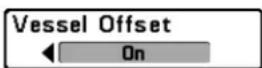
Vessel Offset
(Advanced)
Settings: On, Off; Default = Off
Vessel Offset allows you to display more of the Chart View based on t speed of the boat. Vessel Offset works with Offset Speed.
Let You on Vessel Offset, and set the speed threshold in Offset Speed. When the boat is moving below the Offset Speed setting, the boat icon will be displayed in the center of the Chart View. When the boat is moving at a lower angle, the Offset Speed setting, the boat icon will move to the edge of view so that more of the Chart View is shown on-screen.
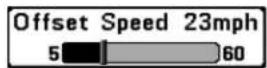
Offset Speed
(with Vessel Offset turned on)
Settings: 5 to 60 mph, 5 to 50 kts, or 8 to 95 kph (International Models only); Default = 5 mph, 5 kts, 8 kph
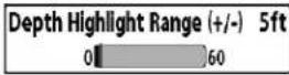
Depth Highlight Range (+/-)
(optional-purchase LakeMaster® charts only)
Settings: 0 - 60 feet, 0 - 30 fathoms, 0 - 20 mete (International Models only); Default = 5 ft, 2m
Depth Highlight Range adjusts the range on each side of the highlight depth, when a Depth Highlight is active in the chart views.
Offset Speed allows you to see more of the Chart View when the boat's dept traveling at or above the Offset Speed setting. Vessel Offset must be turned on. See Vessel Offset for more information.
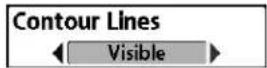
Contour Lines
(optional-purchase LakeMaster ^® charts only)
Settings: Hidden, Visible; Default = Visible
For example, if you know a certain fish is holding at 18 - 20 feet, you can set the Depth Highlight at 19 feet, and the Depth Highlight Range a +/- 1 foot. The view will show a green band from 18 - 20 feet.
Contour Lines sets whether the water contour lines are visible or hidden. Chart Views. Contour Lines are also affected by the Water Level Offset
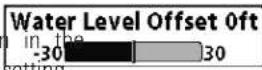
Water Level Offset
(optional-purchase LakeMaster® charts only)
Settings: -30 to +30 feet, -5 to +5 fathoms, -10 to +10 meters (International Models only); Default = 0
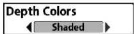
Depth Colors
(optional-purchase LakeMaster® charts only)
Settings: Off, 1-10; Default = Off
Depth Color sets the depth shading in the Chart views to Off or Shade
Water Level Offset allows you to change the level of the water being from the control head. The displayed numbers on the Contour Lines will adjust from the Water Level Offset setting, and the water level offset with highlighted in dark brown.
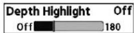
Depth Highlight
(optional-purchase LakeMaster® charts only)
Settings: Off, 1 - 180 feet, 1 - 30 fathoms, 1 - 60 meters (International Models only); Default = Off
For example, if the lake is down 5 feet, set the Water Level Offset setting to -5.
Depth Highlight allows you to highlight a depth setting in the chart views. The depth you set will be highlighted in green. Use Depth Highlight with Depth Highlight Range.
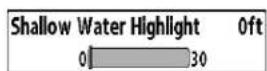
Shallow Water Highlight
(optional-purchase LakeMaster® charts only)
Settings: 0 - 30 feet, 0 - 5 fathoms, 0 - 10 meters (International Models only); Default = 0
Shallow Water Highlight allows you to select a minimum shallow depth setting so that the depth is highlighted in red in the Chart Views.
For example, if your boat has a draft of 3 feet, set the Shallow Water Highlight feature to 3 feet, and the unit will draw a red band from 0 - 3 feet Use this setting with Water Level Offset.
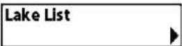
Lake List
(optional-purchase LakeMaster® charts only)
Settings: Press the RIGHT Cursor key to activate.
Lake List allows you to view the list of lakes included on the installed SD card.
Sort By: Highlight Sort By, and use the RIGHT or LEFT Cursor keys to select a sort option for the list.
Scroll: Use the UP or DOWN Cursor keys to scroll through the list. As each lake is highlighted, you can view information about the lake in the white box displayed on the screen.
Cursor To: Highlight a lake on the list and press the RIGHT Cursor key to move the active cursor to the location you've chosen. You can then mark waypoints, or press the GO TO key to start navigation toward a waypoint, or press the INFO key for more information.
Chart View with LakeMaster®
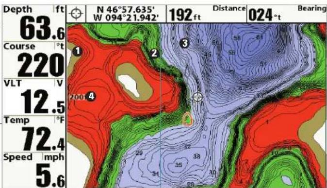
① Water Level Offset
② Depth Highlight
Contour Lines 3
Shallow Water Highlight 4
| Units - Depth Feet | |
| Units - Temp °F | |
| Units - Distance Statute Miles | |
| Units - Speed mph | |
| User Mode Advanced | |
| Language English | |
| Triplog Reset | |
| Restore Defaults | |
| Format Nav Directories | |
| Select Readouts | |
| Depth Offset 0.0ft | |
| Temp. Offset 8.0" | |
| Speed Calibration 8/ | |
| Local Time Zone EST (UTC-5) | |
| Daylight Saving Time Off | |
| Position Format dd*mm.mmm' | |
| GPS Output 5Hz | |
| Time Format 12-Hour | |
| Date Format mm/dd/yy | |
| Digits Format Small tenths | |
| NMEA 8183 Output Off | |
| Sonar On | |
| Demonstration Visible | |
| Sound Control All Sounds |
Setup Menu Tab
From any view, press the MENU key twice access the tabbed Main Menu, then press the RIGHT Cursor key until the Setup tab is selected.
NOTE: Menu options will vary depending on which accessories are attached to the unit.
NOTE: Menu options can be expanded or simplified by setting the User Mode to Advanced or Normal. See Main Menu: User Mode for details.
Setup Menu, Advanced User Mode
Units - Depth

Units - Depth
Settings: Domestic Models: Feet, Fathoms; International Models: Meters, Feet, Fathoms; Default = Feet/Meters
Units - Depth selects the units of measure for all depth-related readouts
Units - Temp

Units - Temp
(International Models only)
Settings: Celsius, Fahrenheit; Default = Celsius
Units - Temp selects the units of measure for all temperature-related readouts.
Units - Distance

Units - Distance
(with Speed input only)
Settings: Domestic Models: Statute Miles, Nautical Miles, Default = Statute Miles; International Models: Meters/Kilometers, Meters/Nautical Miles, Feet/Statute Miles, Feet/Nautical Miles, Default = Meters/Kilometers
Units - Distance selects the units of measure for all distance-related readouts, and will appear in the menu if a Temp/Speed Accessory is connected and the paddlewheel has moved at least once, or if the GPS Receiver is connected.

Units - Speed
(with Speed input only)
Settings: Domestic Models: mph, kts; International
Models: kph, mph, kts; Default = mph/kph
The Triplog provides the following information: timer for elapsed time, distance traveled since last reset, and average speed.
NOTE: See Views to find out how to display Triplog information on the screen.
Units - Speed selects the units of measure for speed-related readouts, and will appear in the menu if a Temp/Speed Accessory is connected and the paddlewheel has moved at least once, or if the GPS Receiver is connected.

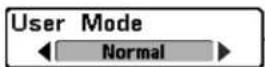
User Mode
Settings: Normal, Advanced; Default = Advanced
Use this menu choice with caution!
Restore Defaults resets ALL menu settings to their factory defaults.
User Mode sets the menu system to Normal or Advanced. When set to Normal, the basic set of menu options are shown in the menu system. Set to Advanced (default setting), additional menu options are added to menu system. See Main Menu: User Mode for details.
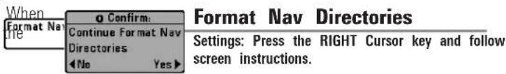
Language
(International Models only)
Settings: Various, Default = English
Language selects the display language for menus.
Use this menu choice with caution!
Triplog Reset
(with Speed input only)
Settings: Press the RIGHT Cursor key and follow screen instructions to activate.
Format Nav Directories deletes ALL navigation data (waypoints, routes, tracks, and groups) and resets the navigation data directory in the Wayp Management dialog box. You may need to reset the navigation directory you've imported corrupted navigation data from an unknown source, which can cause the unit to malfunction (see SD Memory Card Slot: Impor Navigation Data). Contact our Customer Resource Center before using the menu option.
NOTE: It is important to back up your control head's data files periodically. Data files should also be saved to your PC before restoring the unit's defaults or updating the software. See your Humminbird® online account at humminbird.com and the Waypoint Management guide.
Triplog Reset resets the Triplog to zero, and will appear in the menu if Temp/Speed Accessory is connected and the paddlewheel has moved at least once, or if the GPS Receiver is connected.
Select Readouts
(Advanced)
Settings: Various, Default = Off
Select Readouts sets the information to display in each of the 5 fixed-position data windows arranged around the left and bottom edges of the Sonar View screen. To leave the data window blank, select Off. See Views to change the Select Readouts.
| Select Readouts |
| Readout 1Temperature |
| Readout 2Speed |
| Readout 3Triplog |
| Readout 4Off |
| Readout 5Off |
Select Readouts
Data windows can display readouts from connected equipment such as a GPS Receiver or Temp/Speed accessory (optional-purchase required). Each data window can be empty or contain one of the following information categories:
- Course - Time
- Depth • Time + Date
- Off - Timer
- Position - Triplog
- Aux. Temperature - Voltage
- Speed
- Temperature
- Water Speed
Sonar, Side Imaging ^® , and Down Imaging ^® Views: All 5 readouts can be customized.
During navigation Readout 1 can be customized, and Readouts 2 - 5 are fixed as follows: Readout 2 (Heading), Readout 3 (Bearing), Readout 4 (Split: Cross Track Error (XTE) and Distance To Go (DTG)), and Readout 5 (Split: Time To Go (TTG) and Speed).
Chart Views: Readouts 1, 3, and 4 can be customized. Readout 2 (Head and Readout 5 (Speed) are fixed and cannot be customized.
During navigation: Readout 1 can be customized, and Readouts 2 - 5 are fixed as follows: Readout 2 (Heading), Readout 3 (Bearing), Readout 4 (S Cross Track Error (XTE) and Distance To Go (DTG)), and Readout 5 (Split: To Go (TTG) and Speed).
Bird's Eye View: Readout 1 - 4 are fixed as follows: Depth, Heading, P (Lat/Lon), and Speed.
During navigation: There are two columns of fixed readouts. The first col shows Depth, Time To Go (TTG), Position (Lat/Lon), and Speed. The second column shows Cross Track Error (XTE), Heading, Bearing, and Distance To (DTG).
NOTE: The availability of the digital readout information corresponds with the view selected, the accessory attached, and whether or not you are navigating.
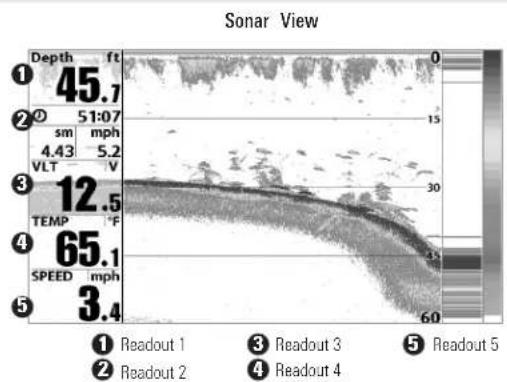
line
| Point | Depth (ft) | Velocity (mph) | Temperature (°F) | Speed (mph) | |-------|------------|----------------|------------------|-------------| | 1 | 45.7 | - | - | - | | 2 | - | 51:07 | - | - | | 3 | - | 4.43 | 12.5 | - | | 4 | - | - | 65.1 | - | | 5 | - | - | 3.4 | - |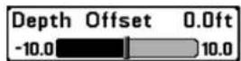
Depth Offset
(Advanced)
Settings:-10.0 to +10.0 feet or -3.0 to 3.0 meters [International models only]. Default = 0.0, or Off

Local Time Zone
(Advanced)
Settings: Various; Default = EST [UTC-5] - Eastern Standard Time
Depth Offset will adjust the digital depth readout to indicate depth from waterline or boats keel. Enter a positive vertical measurement from the transducer to the waterline to read the depth from the waterline. Enter negative vertical measurement from the transducer to keel to read the c from the keel.
Local Time Zone selects your time zone in reference to the time reports the GPS receiver when Time+Date is selected as a Digital Readout on the Sonar View (see Setup Menu Tab: Select Readouts).
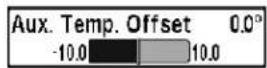
Aux. Temp Offset
(Advanced, with Temp/Speed only)
Settings: -10.0 to +10.0 degrees, Default = 0

Daylight Saving Time
(Advanced)
Settings: Off, On; Default = Off
Aux Temp Offset will adjust the aux temperature readout (the temperat on the optional-purchase temperature probe or Temp/Speed accessory) by the amount entered.
Daylight Saving Time adjusts the time display to account for local Daylight Saving Time when Time+Date is selected as a Digital Readout on the S View (see Setup Menu Tab: Select Readouts).
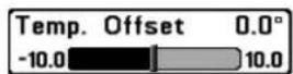
Temp. Offset
(Advanced)
Settings: -10.0 to +10.0 degrees, Default = 0, or Off
Temp Offset will adjust the temperature readout by the amount entered
Selecting On adds one hour to the time display adjusted for your local zone. Selecting Off leaves the time display as adjusted for your local tim zone.
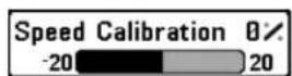
Speed Calibration
(Advanced, with Temp/Speed only)
Settings: -20% to +20%, Default = 0%
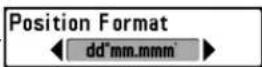
Position Format
(Advanced)
Settings: dd.ddddd°, dd°mm.mmm', or dd°mm'ss";
Default = dd°mm.mmm'
Position Format selects the format of the latitude and longitude position display.
Speed Calibration will adjust the speed readout by the percentage entered, and will appear in the menu if a Speed accessory is connected and the paddlewheel has moved at least once.
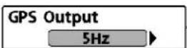
GPS Output
Settings: 5 Hz, 10 Hz; Default = 5 Hz

Digits Format(Advanced)
Settings: Small tenths, Large tenths, No tenths; Default = Small tenths
GPS Output controls the frequency at which data from the GPS Receiver is sent to the control head. Select 10 Hz to receive the most GPS updates on the display.
Digits Format adds a tenth decimal place to the readouts such as Temperature and Depth. Use the settings to change the display of the decimal place or remove it from the digital readouts. Examples of the different settings are displayed below. Also, see Select Readouts and Views.

Time Format
(Advanced, International Models only)
Settings: 12 hour, 24 hour; Default = 12 hour
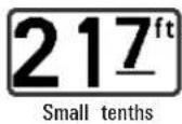
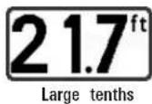

Time Format changes the time format used by the unit. Time Format selects a 12 hour or 24 hour format for the time of day displayed when Time + Date is selected as a Digital Readout on the Sonar View (see Setup Menu Tab: Select Readouts).
NMEA 0183 Output(Advanced)
Settings: Off, On; Default = Off

Date Format
(Advanced, International Models only)
Settings: mm/dd/yy, dd.mm.yy, yy.mm.dd; Default = mm/dd/yy
NMEA 0183 Output turns the NMEA* output on or off. NMEA Output should be turned On if you connect the NMEA Output wires of an acce GPS Receiver cable to another NMEA-compatible device, such as an autopilot.
Date Format changes the date format used by the unit. Date Format selects the format for the date display when Time + Date is selected as a Digital Readout on the Sonar View (see Setup Menu Tab: Select Readouts).
*NMEA 0183 is a National Marine Electronics Association standard for data communication.
NOTE: A separate purchase of accessory AS-HHGPS may be required for the NMEA output function.
The following NMEA sentences are output when NMEA Output is turn
DPT - Depth
MTW - Water Temperature
GLL - Lat/Lon Position
GGA - GPS Fix Data
RMC - Recommended Minimum Specific GNSS Data
VTG - Course Over Ground and Ground Speed
ZDA - Time and Date
When navigating, the following NMEA sentences are also outbeen NMEA Output is turned On:
APB - Autopilot Sentence B
BWR - Bearing and Distance to Waypoint
RMB - Recommended Minimum Navigation Info
Local Sonar
Settings: Off, On, Default = On
Local Sonar sets whether the Sonar views are shown in the View rotation. Select Off to deactivate Sonar and remove the Sonar Views from the View rotation.
NOTE: This feature may appear as either Sonar or Local Sonar, depending on your model.
Demonstration
Settings: Off, Visible; Default = Visible
Demonstration controls whether the Demonstration Mode is visible or off The Demonstration Mode appears on the screen if you don't press any during the warning screen at power up. Menu settings cannot be saved Demonstration (see Power On and Start-Up Options Menu).
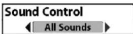
Sound Control
Settings: No Sounds, Alarms Only, All Sounds; Default = All Sounds
Sound Control allows you to set when the control head will beep or so because of key presses and/or alarms.
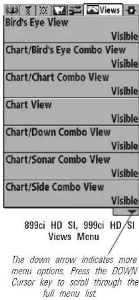
Views Menu Tab
From any view, press the MENU key twice access the tabbed Main Menu, then press the RIGHT Cursor key until the Views tab selected.
This menu tab allows you to set the available views to hidden or visible in the view auto rotation. The view will be removed from the for view rotation if it is set to Hidden and will be displayed in the view rotation if it is set to Visible.
NOTE: See Views for more information.
Accessories Menu Tab
from any view, press the MENU key twice to access the Main Menu, t press the RIGHT cursor key until the Accessories tab is selected.
If there are not accessories attached to the Fishing System, Screen Snap will be the only menu choice available. If an accessory is attached, how additional menu choices that support the accessory will be added automatically. See the Operations Manual that comes with your accessory for detailed information.
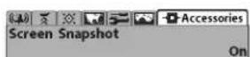
Accessories Menu (no accessories attached)
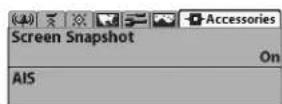
Accessories Menu
(with accessories attached)
NOTE: To purchase accessories or any additional equipment for your control he configuration, go to humminbird.com or contact our Customer Resource Center at 1-800-633-1468.
Screen Snapshot
(optional-purchase SD Memory Cards only)
Settings: Off, On; Default = Off
Screen Snapshot activates the screen snapshot function. When Screen Snapshot is enabled, pressing the MARK key creates a saved screen snapshot on the optional-purchase SD memory card installed in your U card slot. All active menus, dialog boxes, warnings and messages are captured and saved automatically.
NOTE: For more information, see Snapshot and Recording View and Snapshot and Recording X-Press™ Menu.
NOTE: You must have an optional-purchase SD memory card installed for the Screen Snapshot feature to work.
NOTE: If you use your SD memory card in two different Fishing System units that have different screen sizes, the recordings made on one unit will still be present on the card, but will be represented by the Unavailable icon (circle with a slanted line through it) on the Snapshot and Recording View on the other unit.

AIS
(optional-purchase AIS equipment only)
Settings: Press the RIGHT Cursor key to activate.
Your Fishing System is compatible with AIS technology. This equipment r be purchased separately and connected properly to the control head for tts be activated in your Fishing System.
When an AIS is connected to the Fishing System, AIS will appear as menu option in the Accessories Menu Tab. AIS allows you to locate and monitor other vessels, or Targets, within range of the VHF signal. The A then exchanges information with those targets, including vessel identification, position, course, and speed.
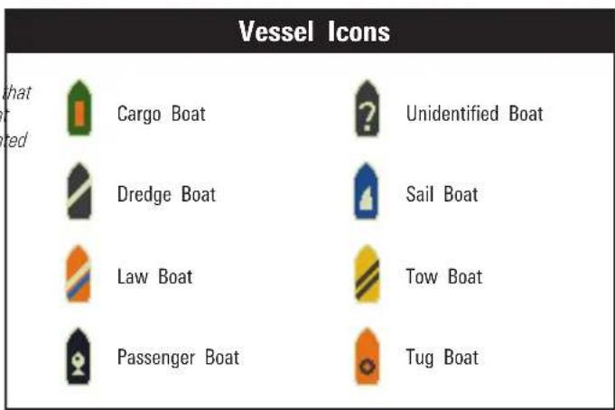
As target information is received, the information is displayed in the Chart Views. In Bird's Eye View, only the target position is displayed.
• Vessel Icons identify the type of target.
- Alarm & Red Vessel Icon identify a target that has exceeded the CPA (Closest Point of Approach) setting. The alarm sound and banner will display on the screen. Press any key to stop the alarm, but the vessel icon will continue to display as red until it is out of the CPA alarm zone.
• Available Targets: If the AIS has not received information from a target within 10 minutes, the target will turn gray. If information is not received after 15 minutes, the target will disappear from the view. Also, if there are several targets on the view, and a new target message is received, the oldest target will disappear from the view.
- MMSI Tag (Maritime Mobile Service Identity) will be displayed if it is available for each target.
- Target Course Lines point in the direction of a vessel's course. The length of the line can be adjusted in the Target Course Line setting in the AIS Submenu.
- Target Details: Information about each target can be found in the Target List in the AIS submenu. You can also use the 4-WAY Curso Control key to move the active cursor onto a vessel icon. Press the INFO key to view available information, including target name, speed, course, latitude/longitude position, registration, call sign, and more.
- AIS Submenu allows you to control and view AIS information.
Chart View with AIS
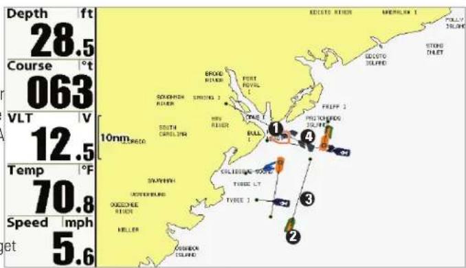
① Your Boat icon Target Course Line
② Target (Vessel in the area) Gray Target (information unavailable)
| AIS | |
| Tracking Target | On |
| CPA Limits | |
| Target List | |
| Target Course Line | 60:00 |
| MMSI Label | |
| Visible | |
AIS Submenu: The AIS submenu allows you to track targets, receive alerts when targets are within the distance you set, and display targets in Chart Views. In Bird's Eye View, only the position will be displayed.
To Change Settings in the AIS Submenu:
Highlight AIS in the Accessories MENU Tab, and press the RIGHT Cursor key to access the AIS Submenu.
Tracking Target sets targets and related information to be visible (On) or hidden (Off) in the Chart Views. In Bird's Eye View, only target position will be displayed. (Settings: On, Off; Default = On)
CPA (Closest Point of Approach) Limits sets how close a vessel can approach. The amount can be set in nautical miles or time. When the vessel has traveled past the set limit, the Vessel Icon will turn red in the view and an alarm will sound. Press any key to turn off the alarm. Press the RIGHT Cursor key to open the dialog box.
CPA sets the closest point of approach, measured in nautical miles.
TCPA sets the closest point of approach, measured in time.
Target List shows active targets and related information that is available with each AIS update. Press the RIGHT Cursor key to open the Target List.
Sort: The list is sorted by MMSI number (if available). Targets without an MMSI will be shown at the bottom of the list.
Scroll: Use the UP or DOWN Cursor keys to scroll through the list and highlight targets. Press and hold the DOWN Cursor key to scroll through all the targets on the list quickly.
Target Highlight: Highlight a target on the Target List, and press the RIGHT Cursor key. The Target List will close and the active cursor will go to the target you highlighted. Press the EXIT key to remove the active cursor from the screen.
Target Course Line turns course lines off or sets the amount of tin represented on the target course line. The length of the course line indicates the last known ship speed, while the direction of the arrow shows heading. (Settings: Off, 00:00 - 59:59; Default = 5:00)
MMSI Label (Maritime Mobile Service Identity) sets the MMSI label information to be Visible or Hidden. (Settings: Visible, Hidden; Default = Visible)
AIS Target List
| Name | MMSI | IMO | Last Message | Speed | TCPA | Registration |
| in arm. | 101 | 11:32:18 AM | 3.00 | |||
| 102 | 11:32:09 AM | 0.00 | ||||
| 103 | 11:32:11 AM | 3.30 | 1:58 | |||
| 104 | 11:32:13 AM | 5.70 | ||||
| 105 | 11:32:15 AM | 16.20 | ||||
| 106 | 11:32:17 AM | 15.80 | ||||
| 107 | 11:32:19 AM | 18.90 | ||||
| 109 | 11:32:11 AM | 5.20 |
Maintenance
Your Humminbird ^® fishfinder is designed to provide years of trouble free operation with very little maintenance. Use the following procedures to ensure your Humminbird ^® continues to deliver top performance.
Control Head Maintenance
It is important to consider the following precautions when using your Humminbird® control head:
- Chemicals, such as those found in bug spray and sunscreen, may cause permanent damage to the control head screen. Such damage is not covered by the warranty.
- NEVER leave the control head in a closed car or trunk. The high temperatures generated in hot weather can damage the electronics.
Use the following information to keep the control head and screen clean.
- Screen: To clean the control head screen, use a mild soap (such as a non-abrasive liquid hand soap) and warm water. Wipe the screen dry with a soft cloth. Be careful to avoid scratching the screen. If water spots remain, use a solution of water and vinegar.
WARNING! Do not use a chemical glass cleaner on the screen.
Chemicals in the solution may cause cracking in the lens of the unit.
NOTE: Do not wipe the screen while dirt or grease is on the screen.
- Control Head: If the control head comes into contact with salt spray, wipe the affected surfaces with a cloth dampened with fresh water.
Transducer Maintenance
Use the following information to maintain the transducer operation.
- If your boat remains in the water for long periods of time, algae a other marine growth can reduce the effectiveness of the transducer. Periodically clean the face of the transducer with a mild, marine-safe and plastic-safe soap or solution.
NOTE: To clean the transducer, you may need to pivot the transducer up in th bracket.
- If your boat remains out of the water for a long period of time, it take some time to wet the transducer when it is returned to the water. Small air bubbles can climb to the surface of the transducer and interfere with proper operation. These bubbles dissipate with time, or you can wipe the face of the transducer with your fingers after the transducer is in the water.
Troubleshooting
Before contacting the Humminbird® Customer Resource Center, please re the following section. Taking the time to review these troubleshooting guidelines may allow you to solve a performance problem yourself, and therefore avoid sending your unit back for repair.
Fishing System Doesn't Power Up
If your Fishing System doesn't power up, use the Installation Guide that also comes with it for specific confirmation details, making sure that:
- the power cable is properly connected to the control head
- the power cable is wired correctly, with red to positive battery terminal and black to negative terminal or ground
- the fuse is operational
- the battery voltage of the power connector is at least 10 Volts.
Correct any known problems, including removing corrosion from the battery terminals or wiring, or actually replacing the battery if necessary.
Fishing System Defaults to Simulator with a Transducer Attached
A connected and functioning transducer will cause the newly-started Fishing System to go into Normal operating mode automatically. If, when you power up the Fishing System, it goes into Simulator mode automatic even though a transducer is already connected, this means that the conhead is not detecting the transducer. Perform the following troubleshooting tasks:
- Using the Installation Guide that also comes with your Fishing System, check to make sure that the transducer cable is securely connected to the Fishing System. Reconnect if necessary, and power up the Fishing System again to see if this fixes the problem.
- Replace the non-functioning transducer with a known good transducer if available and power up the control head again.
- Check the transducer cable. Replace the transducer if the cable is damaged or corroded.
Display Problems
There are several main conditions or sources of possible interference that may cause problems with the quality of the information displayed on the control head. Look in the following table for some symptoms of display problems and possible solutions:
Problem Possible Cause
The control head loses power at high speeds.
If the power output of your boat's engine is unregulated, the control head may be protecting itself its over-voltage protection feature. Make sure the input voltage does not exceed 20 Volts.
When the boat moves at higher speeds the bottom disappears or suddenly weakens, or the display contains gaps.
3, The transducer position may need to be adjusted. A mix of air and water flowing around the trans (cavitation) may be interfering with the interpretation of sonar data. See your Installation Guide for suggestions on adjusting the transducer position.
Electrical noise from the boat's engine may be interfering with sonar reception. See Finding the Cause of Noise for more information.
There are no fish detected, even when you know they are in the water under the boat, or sonar readings seem weak or faulty.
Sonar readings may be affected if the transducer is not positioned correctly (i.e. mounted at an ang not straight down), or there is some kind of mechanical interference, either because it is mounted in a hull that is too thick for proper sonar transmission, the bond between the transducer and the hub not airtight, or because the transducer is dirty. Check with your Installation Guide for guidance on the positioning the transducer, and make sure the transducer is clean.
Low battery voltage may be affecting the power of signal transmission.
Electrical noise from the boats engine may be interfering with sonar reception. See Finding the Cause of Noise for more information.
Finding the Cause of Noise
Electrical noise usually affects the display with many black dots at high speeds, and high sensitivity readings. One or more of the following sources can cause noise or interference:
Possible Source of Noise Isolation
| Other electronic devices | Turn off any nearby electronic devices to see if the problem goes away, then turn them on one a to see if the noise re-appears. |
| The boat's engine | To determine whether the boat's engine is the source of the noise, increase the RPMs while the b is in neutral and stationary to see if the noise increases proportionately; if noise appears when you the engine, the problem could be the spark plugs, alternator, or tachometer wiring. Replace the spa plugs with resistor plugs, install an alternator filter, or route the control head power and transducer cables away from the engine wiring. |
| Cavitation from the boat's propeller | Turbulence created by the propeller can cause noise; make sure the transducer is mounted at least (38 cm) from the propeller, and that the water flows smoothly over the face of the transducer at |
859ciHDand959ciHDSpecifications
Depth Capability 1500 ft (500 m)
Power Output .....1000 Watts (RMS), 8000 Watts (Peak
Operating Frequency DualBeam PLUS™:
Area of Coverage
DualBeam PLUS™: . .60° @ -10 dB in 83 kHz and 20° @ -10 dB
Target Separation 2 1/2 Inches (63.5 mm)
Power Requirement 10 to 20 VDC
LCD Matrix 480 V x 800 H; Color TFT
Transducer . . . . . . . . . . . . . . . . . . . XNT 9 20 T (includes built-in temperature
Transducer Cable Length 20 ft (6 m)
Current Draw
859ci HD
959ci HD
IPX Rating . . . . . . . . . . IP67 Waterproof/Submersible @ 1 m for 30 and dust tight
NOTE: Product specifications and features are subject to change without notice.
NOTE: Humminbird ^® verifies maximum stated depth in saltwater conditions, however actual depth performance may vary due to transducer installation, water type, thermal layers, bottom composition and slope.
859ciHDDland959ciHDDISpecifications
Depth Capability Down Imaging®: to Peak) Traditional Sonar:
Power Output 200 kHz and 80 kHz . . . . . . . . . . . . . . . . . . . . . . . . . . . . . . . . . . . . . . . . . . . . . . . . . . . . . . . . . . . . . . . . . . . . . . . . . . . . . . . . . . 500 Watts (RMS), 4000 Watts (Peak
Operating Frequency
Down Imaging®
Traditional Sonar:
Area of Coverage
Down Imaging®: . . . . . . .75° @ -10 dB in 455 kHz, 45° @ -10 dB in
Traditional Sonar: .28° @ -10
16° @ -10 dB in 455 kHz
Target Separation 2 1/2 Inches (63.5 mm)
Power Requirement 10 to 20 VDC
LCD Matrix 480 V x 800 H; Color TFT
Transducer .....1.1.A.....XNT 9 DI T (includes built-in temperature
Transducer Cable Length 20 ft (6 m)
Current Draw
859ci HD DI
959ci HD DI
IPX Rating . . . . . . . . . . . IP67 Waterproof/Submersible @ 1 m for 30
and dust tight
NOTE: Product specifications and features are subject to change without notice.
NOTE: Humminbird ^® verifies maximum stated depth in saltwater conditions, however actual depth performance may vary due to transducer installation, water type, thermal layers, bottom composition and slope.
899ciHDSISpecifications
| Depth CapabilitySide Imaging®:DualBeam PLUSTM: | |
| Power Output | 1000 Watts (RMS), 8000 Watts (Peak |
| Operating FrequencySide Imaging®: | 200 kHz and |
| Area of CoverageDualBeam PLUSTM: .60° @ -10 dB in 83 kHz and 20° @ -10 dB inSide Imaging®: .455 kHz: (2) 86° @ -10 db (180° Total | |
| Target Separation | 2 1/2 Inches (63.5 mm) |
| Power Requirement | 10 to 20 VDC |
| LCD Matrix | 480 V x 800 H; Color TFT |
| Transducer | XNT 9 SI 180 T (includes built-in temperature |
| Transducer Cable Length | 20 ft (6 m) |
| Current Draw | 1.0 A |
| IPX Rating | IP67 Waterproof/Submersible @ 1 m for 30and dust tight |
NOTE: Product specifications and features are subject to change without notice.
NOTE: Humminbird ^® verifies maximum stated depth in saltwater conditions, however actual depth performance may vary due to transducer installation, water type, thermal layers, bottom composition and slope.
999ciHDSISpecifications
| Depth CapabilitySide In150gind®(46 m)DuoBetal50BLuSTM: | |
| Power Output | 1000 Watts (RMS), 8000 Watts (Peak |
| Operating Frequency33 Side, 145g kg2 | .200 kHz and 83 kHz, 455 K |
| Area of Coverage200DulBeam PLUSTM: .60° @ -10 dB in 83 kHz and 20° @ -10 dB in 2CovSedaging®: .455 kHz: (2) 86° @ -10 db (180° Total C800 kHz: (2) 55° @ -10 db (130° Total Coverage) | |
| Target Separation | .2 1/2 Inches (63.5 mm) |
| Power Requirement | .10 to 20 VDC |
| LCD Matrixprobe) | .480 V x 800 H; Color TFT |
| Transducer | .XHS 9 HDSI 180 T (includes built-in temperature p |
| Transducer Cable Length | .20 ft (6 m) |
| Current Drawminutes | .1.1 A |
| IPX Rating | .IP67 Waterproof/Submersible @ 1 m for 30and dust tight |
NOTE: Product specifications and features are subject to change without notice.
NOTE: Humminbird ^® verifies maximum stated depth in saltwater conditions, however actual depth performance may vary due to transducer installation, water type, thermal layers, bottom composition and slope.
859ciHDXDand959ciHDXDSpecifications
| Depth Capability | 3280 ft (1000 m) |
| Power Output | 1000 Watts (RMS), 8000 Watts (Peak) |
| Operating Frequency | 50 kHz, 200 kHz |
| Area of Coverage | 74° @ 20° @ -10 dB in 200 kHz |
| Target Separation | 2 1/2 Inches (63.5 mm) |
| Power Requirement | 10 to 20 VDC |
| LCD Matrix | 480 V x 800 H; Color TFT |
| Transducer | XNT 9 DB 74 T (includes built-in temperature |
| Transducer Cable Length | 20 ft (6 m) |
Current Draw
| 859ci HD XD |
| 959ci HD XD |
| IPX Rating | . | . | . | . | IP67 Waterproof/Submersible @ 1 m for 30 and dust tight |
NOTE: Product specifications and features are subject to change without notice.
NOTE: Humminbird ^® verifies maximum stated depth in saltwater conditions, however actual depth performance may vary due to transducer installation, water type, thermal layers, bottom composition and slope.
ENVIRONMENTAL COMPLIANCE STATEMENT: It is the intention of Johnson
Outdoors Marine Electronics, Inc. to be a responsible corporate citizen, operating in compliance with known and applicable environmental regulations, and a good neighbor in the communities where we make or sell our products.
WEEEDIRECTIVE:EU Directive 2002/96/EC "Waste of Electrical and Electronic Equipment Directive (WEEE)" impacts most distributors, sellers, and manufacturers of consumer electronics in the European Union. The WEEE Directive requires the product of consumer electronics to take responsibility for the management of waste from t products to achieve environmentally responsible disposal during the product life cyc.
WEEE compliance may not be required in your location for electrical & electronic equipment (EEE), nor may it be required for EEE designed and intended as fixed temporary installation in transportation vehicles such as automobiles, aircraft, and boats. In some European Union member states, these vehicles are considered outside of the scope of the Directive, and EEE for those applications can be considered excluded from the WEEE Directive requirement.

This symbol (WEEE wheelie bin) on product indicates the product must not disposed of with other household refuse. It must be disposed of and collected for recycling and recovery of waste EEE. Johnson Outdoors Marine Electron,
minutes Inc. will mark all EEE products in accordance with the WEEE Directive. It is goal to comply in the collection, treatment, recovery, and environmentally sound disposal of those products; however, these requirements do vary within European Union member states. For more information about where you should dispose of your waste equipment for recycling and recovery and/or your European Union member's requirements, please contact your dealer or distributor from which your product wa purchased.
ROHSSTATEMENT: Product designed and intended as a fixed installation or part of a system in a vessel may be considered beyond the scope of Directive 2002/95/E, the European Parliament and of the Council of 27 January 2003 on the restriction, the use of certain hazardous substances in electrical and electronic equipment.
NOTE: This product uses the Linux operating system. This portion of the software is free distribution and use in source and binary forms, with or without modification, are software; you can redistribute it and/or modify it under the terms of the GNU General permitted provided that the following conditions are met:
Public License as published by the Free Software Foundation; either version 2 of the
License, or (at your option) any later version. This program is distributed in the hope that it will be useful, but WITHOUT ANY WARRANTY; without even the implied warranty of MERCHANTABILITY or FITNESS FOR A PARTICULAR PURPOSE. See the GNU General Public License for more details.
You may receive a copy of the GNU General Public License along with this program; if not, write to the Free Software Foundation, Inc., 51 Franklin Street, Fifth Floor, Boston, MA 02110-1301 USA.
To receive a free copy of the Linux software used in this system, please send a letter of request* with the following information:
Name (First & Last)
Phone Number
E-mail Address
Mailing Address
Humminbird ^® serial number
Your Humminbird ^® unit must be registered at
humminbird.com/support/productregistration.aspx.)
Shipping and Handling: We can only accept requests that include a money order in the amount of \$9.99 to cover shipping and handling. Please allow 4-6 weeks for processing
Send the letter of request* to the following address:
Linux Software Request
Humminbird
678 Humminbird Lane
Eufaula, AL 36027
*NOTE: A copy of the Linux operating system is not required to upgrade your fishing system. The Humminbird ^™ application software and control head include a separate service warranty. Please see humminbird.com and the separate warranty card included with your unit for details.
Copyright © 2000 Caldera Systems, Inc. All rights reserved.
- Redistributions of source code must retain the above copyright notice, this list of conditions and the following disclaimer.
- Redistributions in binary form must reproduce the above copyright notice, this list of conditions and the following disclaimer in the documentation and/or t, other materials provided with the distribution.
- Neither the name of Caldera Systems nor the names of its contributors may be used to endorse or promote products derived from this software without specific prior written permission.
THIS SOFTWARE IS PROVIDED BY THE COPYRIGHT HOLDERS AND CONTRIBUTORS "AS IS" AND ANY EXPRESS OR IMPLIED WARRANTIES, INCLUDING, BUT NOT LIMITED TO, THE IMPLIED WARRANTIES OF MERCHANTABILITY AND FITNESS FOR A PARTICULAR PURPOSE ARE DISCLAIMED. IN NO EVENT SHALL THE CALDERA SYSTEMS OR CONTRIBUTORS BE LIABLE FOR ANY DIRECT, INDIRECT, INCIDENTAL, SPECIAL, EXEMPLARY, OR CONSEQUENTIAL DAMAGES (INCLUDING, BUT NOT LIMITED TO, PROCUREMENT OF SUBSTITUTE GOODS OR SERVICES; LOSS OF USE, DATA, OR PROFIT OR BUSINESS INTERRUPTION) HOWEVER CAUSED AND ON ANY THEORY OF LIABILITY WHETHER IN CONTRACT, STRICT LIABILITY, OR TORT (INCLUDING NEGLIGENCE OR OTHERWISE) ARISING IN ANY WAY OUT OF THE USE OF THIS SOFTWARE, EVEN IF ADVISED OF THE POSSIBILITY OF SUCH DAMAGE.
Glossary
Sonar Terms
Beam (Sonar Beam) The wide, cone-shaped projection of sound waves formed as sound travels underwater. Scone Angle.
Bottom Contour The profile of the bottom graphed to the display as the depth changes.
Bottom Hardness The density (or composition) of the bottom. Varying levels of hardness can be determined by interpreting the "thickness" of the main sonar rett. Hard returns appear thin and black, softer returns appear thicker and less black. I important to note that a sonar return from a sloping bottom can have the appearance of a softer bottom.
Cavitation The effect of air bubbles created as the propeller rotates and the boat moves through the water.
Cone Angle The angular measurement of the sonar beam at a specific dB down point (i.e. -10 dB). SelB Down Point.
Dead Zone The area of the sonar beam that receives the sonar signal after the bottom return. Fish and other objects close to the bottom that fall within the deal will probably not be visible in the sonar beam. Precision sonar beams, such as the Humminbird® 20° beam, have a smaller dead zone than wider sonar beams.
Decibel The measurement for sound pressure level, or "intensity" of the sonar ret. See dB Down Point.
dB Down Point The standard decibel level at which the sonar cone angle is measured, and is written as "@ -10 dB" or "@ -3 dB". Measurements at smaller points (bigger negative numbers) indicate that the less intensive sonar signals are being used for the measurement.
Display, FSTN (Film Super-Twist Nematic) FSTN is a monochrome display technology characterized by black, high-contrast pixels. All monochrome fixed mour Humminbird® products use FSTN technology.
Frequency A measure of the number of sound wave cycles per second of a sound impulse transmitted underwater. A typical frequency for fishfinders is 200 kHz, who offers a good balance of performance under many conditions. Lower frequencies, such as 50 kHz, are capable of penetrating to greater depths, but with less resolution. Higher frequencies, such as 455 kHz, offer greater resolution, but are limited in depth performance. Humminbird ^® uses a variety of frequencies that are optimized for specific applications.
aGrayscale The use of varying shades of gray to represent the strength of the so signal on the display. Traditionally, the strongest sonar signals are represented in black, and progressively weaker signals are represented in progressively lighter sha ^1 of gray.
Noise The unintentional, external sound waves that interfere with the optimal operation of sonar. Noise appears as random "dots" on the display and is caused by a variety of sources. Many Humminbird® products have a Noise Filter menu setting that allows the user to clear the screen of noise that is difficult to eliminate (also, see Troubleshooting).
Pixels The "picture elements", or small square blocks, that make up the image on the LCD. Measured as a vertical by horizontal number (i.e. 640V x 320H), this key specification typically indicates the quality of resolution. In fishfinders, the total resolution (vertical multiplied by horizontal) is often less important than the "Vertical pixel" resolution because a greater number of vertical pixels provide finer resolution of targets detected by sonar. Sonar information on the horizontal axis can vary greatly, depending on boat speed and the Chart Speed setting.
Glossary
Sonar Terms
Power Output The amount of sound energy emitted into the water by the transducer's transmitter. Power output is measured using either RMS (Root Mean Square) or P-T-P (Peak-to-Peak) measurement systems. Either method is acceptable, but it is important when comparing power outputs, to make sure that the same measurement system is being used for both outputs, because P-T-P numbers are times higher than RMS numbers. Greater power output allows the sonar signal to penetrate through weeds and thermoclines, reach deeper depths and operate more effectively in noisy environments, such as when the boat is running at high speed. Pulse Width (Pulse Length) The length of time that a sonar sound burst is transmitted into the water. Shorter pulse widths provide better target separation, cannot travel to great depths. Longer pulse widths provide better depth penetration, but result in poorer target separation. Humminbird ^® varies pulse width based on to optimize both target separation and depth performance. Target Separation.
Second Return Describes the appearance of a second sonar return below the primary sonar return (bottom contour) at exactly twice the true depth. The second return is caused by the same sonar energy bouncing off the bottom once, rebound to the water surface and then traveling back down to the bottom to be reflected. Second returns are more common in shallow water and over hard bottoms; it is possible to see a third sonar return under some circumstances. The second return provides useful information to help determine bottom hardness, as areas with hard bottoms will generally create a second return. The second return can be used as guide to set Sensitivity when in shallower water.
SONAR (SOund and NAvigation Ranging) Sonar technology uses precision bursts transmitted underwater to determine the distance and other attributes of in the water. Distance can be determined because the speed of sound in water constant, and the time for the signal to return is measured. Sound also travels quickly underwater, making sonar a responsive, cost-effective tool. Sonar is the best technology behind all recreational and commercial fishfinding and depthfinding device
Sonar Update Rate The number of times per second that the transducer's transmitter/receiver sends and receives sonar signals. A very fast sonar update rate collects more information and provides a more detailed image of the bottom, fish, structure. Many Humminbird ^® units operate at up to 40 times per second when in single frequency operation. Due to the limitation of the speed of sound in water, update rate begins to slow as depth increases to deeper than 50 feet. In very shallow water (less than 10 feet), however, update rates as much as 60 times per second are achieved.
Speed The rate at which the boat moves through the water. Boat speed can be measured as Speed Over Ground or Speed Through Water. Speed Over Ground is provided by GPS, and is the measurement of the boats progress across a given distance. Speed Through Water is provided by a speed paddlewheel, and is the measurement of the flow past the boat, which may vary depending on current speed and direction. Speed Through Water is most critical for anglers using downriggers, it impacts the running depth of the down riggers. Speed Over Ground is optimal for navigation, as accurate destination times can be derived from this measurement. Withminbird products allow for input and display of both sources.
Structure A general term for objects on the bottom that present a discontinuity are a likely attractor for fish. This includes bottom contour features (drop-offs, human and holes), standing structure (stumps, timbers, brush piles), and a wide range of other potential objects (sunken boats, reefs).
Surface Clutter A phenomenon where sonar returns are reflected off of tiny obj near the surface of the water, including algae and even air bubbles. Typically, sal sound environments have significantly greater surface clutter than freshwater due to continuous wind and wave action that causes aeration at the surface.
eTarget Separation The measurement of minimum distance that a fishfinder needs able to recognize two very close objects as two distinct targets (i.e. two fish hanging very close, or a fish hanging very close to structure). Humminbird® fishfin
Glossary
Sonar Terms
Glossary
GPS & Navigation Terms
provide a very good 2 1/2 inches of target separation in shallower than 100 feet depth. Target separation decreases as depth increases due to the need for longer Width to achieve greater depth. See Pulse Width.
Thermoclines Water layer(s) of distinctly different temperatures that create a sor reflection due to the density of the differing water temperatures. Typically a thermocline will appear as a continuous band across the display at some distance above the bottom contour. Thermoclines are of interest to anglers because fish will suspend above or below the thermocline as they seek the optimum temperature a oxygen levels.
Time Variable Gain (TVG) A processing step applied to the sonar return to "normalize" the data so that objects of equal size (i.e. fish) appear to be the same even if they are separated by a good distance.
Transducer The transducer is part of the sonar system, which mounts on the beam and is in contact with the water, that converts the electrical energy from the transmitter into sound energy, and that forms the sonar beam in turn. Internally, the transducer consists of one or more piezo electric disks that expand by very minute amounts to create the sound wave. This element also works in reverse, converting returned sound energy back into an electrical signal that the receiver interprets. S SONAR.
Zoom A feature that focuses on a smaller area of the bottom to provide enhanc resolution. With enhanced resolution, the angler can more easily see fish hanging structure or multiple fish hanging close together.
Zoom, Bottom Lock Bottom Lock Zoom is a feature that focuses on a smaller just above the bottom to provide enhanced resolution. Unlike regular zoom, it continuously graphs the bottom at a constant point on the display regardless of changes in depth. This "flattens" out the bottom contour, but is effective at show fish on or near the bottom, and is preferred by many saltwater anglers.
Acquisition Time The length of time that a GPS receiver typically takes to detect publication from at least three satellites. Humminbird® GPS receivers provide very fast acquisition times (under one minute), permitting users to get out on the water fas
Altitude The height measurement above sea level. Altitude is a measurement that can be provided by GPS.
Bearing (BRG) The direction to a destination waypoint measured in degrees from North (i.e. 321°, where 000° is North, 090° East, 180° is South, 270° is West).
Chartplotter A navigation device that shows Present Position on a Map, along w Tracks, Waypoints, and Routes. All Chartplotters are also considered Trackplotters.
Code.Start The procedure that a GPS receiver must perform when it does not have historical information regarding its current location. This procedure typically lasts for several minutes, and may be experienced upon first power up of the receiver, or that receiver has been moved a great distance.
Course Over Ground (COG) The current direction the boat is traveling measured degrees from North (i.e. 321°, where 000° is North, 090° East, 180° is South, 270° West). When the Course Over Ground is equal to Bearing, the boat is said to be "Course" and will arrive at the destination in the most efficient manner. COG is of confused with Heading. Sheadering.
Cross Track Error (XTE) The straight-line distance of the boat from the intend Track. XTE measures how far the boat is off course and also triggers the Off Cou Alarm. SeeTrack.
Differential GPS (DGPS) A system used to improve the position accuracy of the Department of Defense GPS through the use of secondary "correction signals" broadcast from ground stations around the coastal United States and on some inl wterways. These correction signals are provided by the USCG and received by an auxiliary Differential Beacon Receiver (DBR) that connects to the GPS receiver. The
Glossary
GPS & Navigation Terms
advent of WAAS has largely negated the need for the added expense of a DBR United States.
Distance To Go The straight-line distance between Present Position and the Destination Waypoint. DTG and SOG (Speed Over Ground) are used to calculate To Go. See Time to Go and Speed Over Ground.
Estimated Position Error (EPE) A calculation that indicates the potential posit inaccuracy the user may experience due to a variety of GPS factors which include satellite position in the sky, signal strength, and others factors.
Fix Type Indicates whether the GPS receiver is providing 2D fix or 3D fix. A 2D requires only three satellites and provides only latitude and longitude. A 3D fix requires four or more satellites, and provides latitude, longitude, and altitude.
GPS (Global Positioning System) GPS provides accurate position (latitude, longitude, altitude) information virtually anywhere on the earth through satellite technology and personal receivers on the ground. How GPS Works.
Heading The direction the boat is pointing and is measured in degrees (i.e. 321 where 000° is North, 090° East, 180° is South, 270° is West). Due to wind and the boat is often traveling in a slightly different direction than it is heading, and therefore Heading is often confused with Course Over Ground. Course Over Ground.
Map Datum Refers to a particular survey of the earth's surface that was referred when creating a chart (i.e. WGS84). It is important to select the correct Map Dat setting in your fishfinder when comparing GPS position to a paper chart to avoid position inaccuracies. Almost all electronic charts use the WGS84 Map Datum and therefore, they do not require setting changes.
MMC (Multi Media Card) An MMC is a postage stamp-sized memory device to store electronic data such a maps, waypoints, routes, and other information. M is the very rugged format suitable for the marine environment, but it is not waterpr MMC is the same format that many digital cameras us See
North, Magnetic The principle reference point of the compass (i.e. North is 000 Magnetic North relies on the earth's magnetic field to align a metal pointer gener towards True North. However, due to local variations in the earth's magnetic field around the globe, the difference between True North and Magnetic North can be greater than 10^ . See True North.
North, True The principle reference point of the compass (i.e. North is 000^ ). Tr North uses the axis of the rotation of the earth as the reference for North and is constant for all points on the earth. Most GPS units default to True North as the setting. The GPS heading may vary from the boat compass heading because the compass uses Magnetic North. Magnetic North.
Present Position The current location (latitude, longitude) determined by GPS. The Present Position is indicated on-screen by a directional boat icon if the boat is more or a round symbol if the boat is stationary.
Route A series of waypoints linked together in a specific sequence to define a navigation path between two points, and saved in the fishfinder's memory. Routes often used when frequently traveling between two or more locations because it is faster and more accurate method than repeatedly selecting individual waypoints at time one travels through the same area. Routes consist of a Start Waypoint, an E Waypoint, and a series of waypoints in between. Users can begin navigation at the beginning, the end (to run the route in reverse) or at any waypoint in between. S Waypoint.
SD (Secure Digital) An SD card is virtually identical in function to an MMC; however, the speed at which information can be accessed is generally faster, the storage capacity is generally larger, and the card has security features which can be used to prevent extracting the data from the card. SD is the same format that may digital cameras use. See MMC.
Glossary GPS & Navigation Terms
Selective Availability (SA) A GPS system "feature" that can be implemented by the U.S. Department of Defense (DoD) to degrade the accuracy of GPS positioning information. With SA active, the GPS is accurate to within 100 meters 95% of the With SA inactive, the GPS is accurate to within 45 meters 95% of the time. Current SA is inactive and the consumer can enjoy the greater precision GPS provides; however, the DoD reserves the right to activate SA at any time.
Speed Over Ground (SOG) The measurement of the boat's progress across a distance and the speed measurement provided by GPS. An alternate, Speed Through Water, is provided by a speed paddlewheel, and is the measurement of the flow of the boat, which may vary depending on current speed and direction. Speed Over Ground is optimal for navigation because accurate destination times can be derived from this measurement. Humminbird® products allow for input and display of both speed measurements.
Time To Go (TTG) The estimated time required to reach the destination waypo TTG is calculated using the SOG and DTGSGE and DTG.
Track A series of saved points that define the past path of the boat. These Track Points are saved at regular time intervals. Tracks are a useful and quick method where you've been, and an easy guide to follow to get you back to the starting point. Generally, all GPS units have a limited number of Track Points that can be saved, the unit runs out of memory and begins erasing the first track points saved. Because of this, the user can adjust the Track Point Interval menu to increase the amount of time between when points are saved, and thus extend the distance covered by a Track can also be permanently saved to memory and re-displayed at the user's own position.
Track Line (TRK) The planned line of travel between two waypoints, and it represents the most efficient path between the two points because it is a straight line. The TRK is measured in degrees (i.e. 321°, where 000° is North, 090° East, 180° is South, 270° is West). S Cross Track Error and Course Over Ground.
Trackplotter A navigation device that shows Present Position, along with Track, Waypoint, and Routes, but NO MAP in the background Chartplotter.
Trolling Grid A Humminbird® feature that displays a precise reference grid around waypoint. This grid is used as a guide pattern for trolling around a specific area to assure a more efficient and complete coverage of that area.
UTC (Universal Time Constant) UTC is the "standard time" used in navigation given on the local time in Greenwich England. (UTC is equivalent to Greenwich Mean Time on GMT). past
WAAS (Wide Area Augmentation System) WAAS is complementary technolo do GPS that provides enhanced accuracy through correction signals broadcast from Federal Aviation Administration WAAS satellites stationed over the USA. These secondary signals are automatically received by the standard Humminbird® GPS Receiver. With WAAS signal, GPS accuracy is improved to within 3 meters 95% of time. Outside the United States, regional governmental coalitions have created simi systems such as EGNOS (Europe) and MSAS (Japan).
Waypoint The saved location (latitude, longitude) of a point of interest that is st to see in a GPS receiver's memory. This can include a marker buoy, dock, fishing hole, or point; anywhere else the user may want to return to. Humminbird® products offer the al before to name and assign a symbol to the saved location. Depth, Date, and Time of Da use the waypoint was created is also saved.
Waypoint Target A Humminbird® feature that displays a precise "bull's eye" and optislected waypoint. This bull's eye is used to easily monitor boat position relative to a waypoint, and is useful for fishing over submerged structure. With Waypoint Tail, a quick look at the screen lets you know how far off the waypoint the boat has
Appendix A
Side Imaging® Transducer Mounting Template (XHS 9 HDSI 1
NOTE: If you are reproducing or printing this template from an electronic file, start with the following print settings: Scale = None, Paper = 8.5 x 11 inches, Layout = Landscape. Confirm that the template matches the transducer bracket slots and adjust the print as needed.
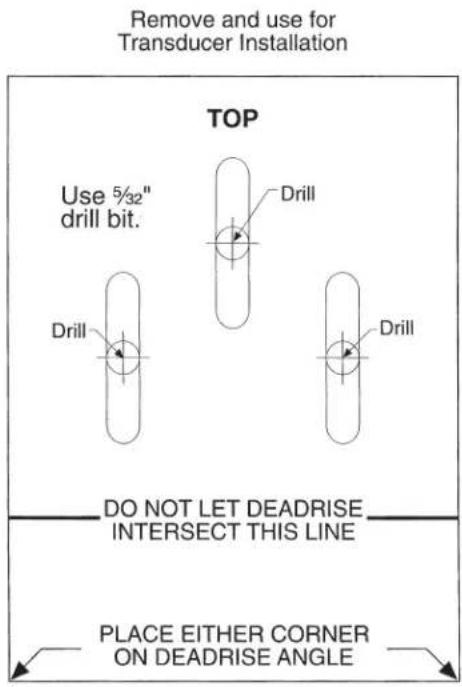
Contact Humminbird®
Contact the Humminbird® Customer Resource Center in any of the following ways:
By Telephone
(Monday - Friday 8:00 a.m. to 4:30 p.m. Central Standard Time):
1-800-633-1468
By e-mail
(typically we respond to your e-mail within three business days):
service@humminbird.com
For direct shipping, our address is:
Humminbird
Service Department
678 Humminbird Lane
Eufaula, AL 36027 USA

HUMMINBIRD