
SR775AX - Cooker SMEG - Free user manual and instructions
Find the device manual for free SR775AX SMEG in PDF.
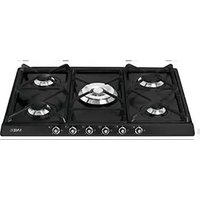


| Product Type | Freestanding Cooker |
| Brand | Smeg |
| Model | SR775AX |
| Overall Dimensions (W x D x H) | 90 x 60 x 85 cm |
| Weight | Approx. 65 kg |
| Power Supply | 220-240 V / 50-60 Hz |
| Power Rating | 11.5 kW |
| Number of Hob Zones | 5 (4 induction + 1 gas wok) |
| Oven Capacity | 70 Liters |
| Energy Class | A+ |
| Cleaning Type | Pyrolytic Self-Cleaning |
| Oven Functions | 8 functions including fan, grill, pizza, defrost |
| Display Type | Digital with Touch Controls |
| Child Lock | Yes |
| Cool Door Technology | Yes (3 layers) |
| Gas Type (if applicable) | Natural Gas / LPG Convertible |
| Material | Stainless Steel with Glass Oven Door |
| Warranty | 2 Years |
Frequently Asked Questions - SR775AX SMEG
User questions about SR775AX SMEG
0 question about this device. Answer the ones you know or ask your own.
Ask a new question about this device
Download the instructions for your Cooker in PDF format for free! Find your manual SR775AX - SMEG and take your electronic device back in hand. On this page are published all the documents necessary for the use of your device. SR775AX by SMEG.
USER MANUAL SR775AX SMEG
INSTRUCTIONSFORTHEUSER:thesecontainuseradvice,thedescription ofthecontrolsandthecorrectproceduresforcleaningandmaintenanceof theappliance.

INSTRUCTIONSFORTHEINSTALLER:theseareintendedforthequalified technicianwhomustinstalltheappliance,setitfunctioningandcarryout aninspectiontest.
1. INSTRUCTIONSFORUSE

THISMANUALISANINTEGRALPARTOFTHEAPPLIANCE.ITMUSTBEKEPTINITS ENTIRETYANDINANACCESSIBLEPLACEFORTHEWHOLEWORKINGLIFEOF THECOOKINGHOB.WEADVISEYOUTOREADTHISMANUALANDALLTHE INFORMATIONITCONTAINSCAREFULLYBEFOREUSINGTHEHOB.ALSOKEEP THESERIESOFNOZZLESPROVIDED.INSTALLATIONMUSTBECARRIEDOUTBY QUALIFIEDPERSONNELINACCORDANCEWITHTHEREGULATIONSINFORCE. THISAPPLIANCEISINTENDEDFORHOUSEHOLDUSEANDCOMPLIESWITHTHE EECDIRECTIVESCURRENTLYINFORCE.THEAPPLIANCEHASBEENBUILTTO CARRYOUTTHEFOLLOWINGFUNCTIONS:COOKINGANDHEATINGFOODS;ALL OTHERUSESARETOBECONSIDEREDIMPROPER. THEMANUFACTURERCANNOTBEHELDLIABLEFORUSEOTHERTHANAS INDICATED.

IFTHEAPPLIANCEISINSTALLEDONBOATSORINCARAVANS,DONOTUSEITAS AROOMHEATER.

DONOTUSETHISAPPLIANCEFORHEATINGROOMS.
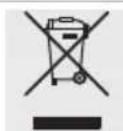
THISAPPLIANCEISMARKEDACCORDINGTOEUROPEANDIRECTIVE2002/96/EC ONWASTEELECTRICALANDELECTRONICEQUIPMENT(WEEE). THISDIRECTIVEDETERMINESTHESTANDARDSFORTHECOLLECTIONAND RECYCLINGOFWASTEELECTRICALANDELECTRONICEQUIPMENTAPPLICABLE THROUGHOUTTHEEUROPEANUNION.

BEFORETHEAPPLIANCEISPUTINTOOPERATION,ALLPROTECTIVEFILMSMUST BEREMOVED.

SUITABLEHEAT-PROOFGLOVESSHOULDBEWORNFORALLOPERATIONS.

DONOTUSESTEELSPONGESANDSHARPSCRAPERSASTHEYWILL DAMAGETHESURFACE. USENORMALNON-ABRASIVEPRODUCTS, INCLUDINGWOODENOR PLASTICUTENSILSIFNECESSARY.RINSETHOROUGHLYANDDRY USINGASOFTCLOTHORAMICROFIBRECLOTH.

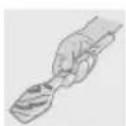

DONOTLEAVETHEAPPLIANCEUNATTENDEDDURINGCOOKINGOPERATIONS WHEREFATSOROILSCOULDBERELEASED. FATSANDOILSMAYCATCHFIRE.

ALWAYSCHECKTHATTHECONTROLKNOBSAREINTHE(OFF)POSITION WHENYOUFINISHUSINGTHEHOB.
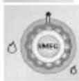

NEVERPLACEPANSWITHBOTTOMSWHICHARENOTPERFECTLYFLATAND SMOOTHONTHECOOKINGHOBRACKS.

NEVERUSECONTAINERSWHICHPROJECTBEYONDTHEOUTSIDEEDGEOFTHE HOB.
2.SAFETYPRECAUTIONS
REFERTOTHEINSTALLATIONINSTRUCTIONSFORTHESAFETYREGULATIONS FORELECTRICORGASAPPLIANCESANDVENTILATIONFUNCTIONS. INYOURINTERESTSANDFORYOURSAFETYITHASBEENESTABLISHEDBYLAW THATTHEINSTALLATIONANDSERVICINGOFALLELECTRICALAPPLIANCESISTO BECARRIEDOUTBYQUALIFIEDPERSONNELINACCORDANCEWITHTHE REGULATIONSINFORCE. OURAPPROVEDINSTALLERSGUARANTEEASATISFACTORYJOB. GASORELECTRICALAPPLIANCESMUSTALWAYSBEDISCONNECTEDBY SUITABLYSKILLEDPEOPLE.

BEFORECONNECTINGTHEAPPLIANCETOTHEPOWERGRID, CHECKTHEDATA ONTHEPLATEAGAINSTTHEDATAFORTHEGRIDITSELF.

THEIDENTIFICATIONPLATECONTAININGTHETECHNICALDATA, SERIALNUMBER ANDBRANDNAMEISINAVISIBLEPOSITIONUNDERTHECASING. DONOTREMOVETHEPLATEONTHECASINGFORANYREASON. BEFORECONNECTINGTHEAPPLIANCE, ENSURETHATITISSETTOTHETYPEOF GASTHATITWILLBESUPPLIEDWITH, CHECKINGTHELABELAPPLIEDUNDER THECASING.

BEFORECARRYINGOUTINSTALLATION/MAINTENANCEWORK, MAKESURETHAT THEAPPLIANCEISNOTCONNECTEDTOTHEPOWERGRID.
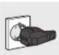
THEPLUGTOBECONNECTEDTOTHEPOWERSUPPLYCABLEANDITSSOCKET MUSTBEOFTHESAMETYPEANDCONFORMTOTHEREGULATIONSINFORCE. THESOCKETMUSTBEACCESSIBLEAFTERTHEAPPLIANCEHASBEENBUILTIN. NEVERDISCONNECTTHEPLUGBYPULLINGONTHECABLE.

IFTHEPOWERSUPPLYCABLEISDAMAGED,CONTACTTHETECHNICALSUPPORT SERVICEIMMEDIATELYANDTHEYWILLREPLACEIT.

THEAPPLIANCEMUSTBECONNECTEDTOEARTHINCOMPLIANCEWITH ELECTRICALSYSTEMSAFETYREGULATIONS.

IMMEDIATELYAFTERINSTALLATION, CARRYOUTABRIEFINSPECTIONTEST, FOLLOWING THE INSTRUCTIONS BELOW. SHOULD THE APPLIANCE NOT FUNCTION, DISCONNECTITFROMTHEPOWERSUPPLYANDCALLTHENEAREST TECHNICALSUPPORTCENTRE. NEVERATTEMPTTOREPAIRTHEAPPLIANCE.

DURINGUSETHEAPPLIANCEBECOMESVERYHOT.TAKECARENOTTOTOUCH THEHEATINGELEMENTS.

THEUSEOFTHISAPPLIANCEISNOTPERMITTEDTOPEOPLE(INCLUDING CHILDREN)OFREDUCEDPHYSICALANDMENTALABILITY,ORLACKINGIN EXPERIENCEINTHEUSEOFELECTRICALAPPLIANCES,UNLESSTHEYARE SUPERVISEDORINSTRUCTEDBYADULTSORPEOPLERESPONSIBLEFORTHEIR SAFETY.

DONOTLETCHILDRENGONEARTHEAPPLIANCEWHENITISINOPERATIONOR PLAYWITHITATANYTIME.

DONOTINSERTPOINTEDMETALOBJECTS(CUTLERYORUTENSILS)INTOTHE SLITSINTHEAPPLIANCE.
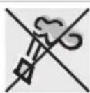
DONOTUSESTEAMJETSFORCLEANINGTHEAPPLIANCE. THESTEAMCOULDREACHTHEELECTRONICS, DAMAGINGTHEMANDCAUSING SHORT-CIRCUITS.

DONOTMODIFYTHISAPPLIANCE.

DONOTSPRAYANYSPRAYPRODUCTSNEARTHEELECTRICALAPPLIANCE WHILEITISINOPERATION. DONOTUSESPRAYPRODUCTSWHILETHEPRODUCTISSTILLHOT.

Themanufacturerdeclinesallresponsibilityfordamagetopersonsorthingscaused bynon-observanceoftheaboveprescriptionsorbyinterferencewithanypartofthe applianceorbytheuseofnon-originalspareparts.
3. ENVIRONMENTAL RESPONSIBILITY
3.1 Ourenvironmentalcare

PursuanttoDirectives2002/95/EC,2002/96/EC,2003/108/EC,relatingtothe reductionoftheuseofhazardoussubstancesinelectricalandelectronic appliances,aswellastothedisposalofrefuse,thecrossedoutbinsymbolon theapplianceindicatesthattheproduct,attheendofitsusefullife,mustbe collectedseparatelyfromotherrefuse.Therefore,theusermustconsignthe productthathasreachedtheendofitsworkinglifetotheappropriateselective collectioncentresforelectricalandelectronicrefuse,ordeliveritbacktothe retailerwhenpurchasinganequivalentproduct,onaoneforonebasis.
Adequateselectivecollectionforthesubsequentforwardingofthe decommissionedproducttorecycling,treatmentandecologicallycompatible disposalcontributestoavoidingpossiblenegativeeffectsontheenvironment andonhealthandpromotestherecyclingofthematerialsofwhichthe applianceconsists.Theillicitdisposaloftheproductbytheuserresultsinthe applicationofadministrativesanctions.
Theproductdoesnotcontainsubstancesinquantitiessufficienttobe consideredhazardoustohealthandtheenvironment,inaccordancewith currentEuropeandirectives.
3.2 Yourenvironmentalcare
Our product's packaging is made of non-polluting materials, therefore compatible with the environment and recyclable. Please help by disposing of the packaging correctly. You can obtain the addresses of collection, recycling and disposal centres from your retailer or from the competent local organisations.

Do not discard the packaging or any part of it, or leave it unattended. It can constitute a suffocation hazard for children, especially the plastic bags.
Your oldappliancealsoneedstobedisposedofcorrectly.
Important: handoveryourappliancetothelocalagencyauthorisedforthe collectionofhouseholdappliancesnolongerinuse.Correctdisposalenables intelligentrecoveryofvaluable materials.
Before disposing of your appliance is important to removed doors and leave shelves in the same position as for use, to ensure that childrenc cannot accidentally becomeetrapped inside during play. It is also necessary to cut the connecting cable to the powers supply, removing it along with the plug.
4.USINGTHEHOB

Before turning on the burners, makes sure that the burners, flame-spreader crowns and racks are fitted correctly.
Intheultra-rapidburner, notchAmustbealignedwithpinB.


4.1 Lightingtheburners
Theburnercontrolledbyeachknobisshownnexttotheknob. The applianceisequippedwithelectronicignition.Simplypresstheknoband simultaneouslyturnitanticlockwisetotheminimumflamesymbol,untillights. Onvalvedmodels,holddowntheknobforabout2secondstokeeptheflamelit andtoactivatethesafetydevice.Theburnermaygooutwhentheknobis released.Ifthishappens,repeattheprocedure,holdingtheknobdownfor longer.
(Onsomemodelsonly)
Double-crownburnerscomprise an auxiliary and rapid burner, controlled by twodifferentknobs which permittouse both burners at the same time to select one or the other as required.


If the burners should go out accidentally, after about 20 seconds as safety device will be tripped, cutting off the gas supply, even if the gas tap is open.
4.2 Practicaltipsforusingtheburners
Forbetterburnerperformanceandminimumgas consumption,panswithflat,evenbasesandwithlids shouldbeused,andtheirsizeshouldbeinproportion to theburner(see"4.3Pandiameters").
During cooking, inorderto avoid burns or damage to the hobtop and to the glass lid (when present), all pansor griddles must be positioned within the cooking hob perimeter and a minimum distance of 3-4 cm must be maintained from the knobs.


Makesurenevertotouchthelidglasswithpotsandpansthatarestillhot. The glasscouldcrackandbreakwiththeheat.
4.3 Pandiameters
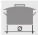
| (*)Burnermin.andmax.∅(incm) | ||
| 1 | Auxiliary | 7 - 18 |
| 2 | Semi-rapid | 10 - 24 |
| 3 | Medium Rapid | 12 - 24 |
| 4 | Large Rapid | 14 - 26 |
| 5 | Double crown ultra-rapid | 12 - 28 |
| 6 | Triple crown ultra-rapid | 22 - 28 |
| 7 | Fishburner | Suitableovalcontainers |
(*)Forburnerreferencenumbers,see“9.7Arrangementoftheburnersonthecooking hob”.
4.4 Using the griddle plate
Afew precautions are necessary if you wish to use a griddle plate:
- leave a gap of at least 160 mm between the edge of the griddle plate and the sidewall;
- ifoneoftheburnersclosetothewoodnearwallisatriplecrownburner, leave a gap of at least 160 mm between this wall and the edge of the griddle plate;
- donotallowtheburnerflamestoextendbeyondtheedgeofthegriddle plate;
- operate the burners underneath the griddle plate for 10 minutes at maximum power, thenturnthemdowntotheminimumsetting. Neverusethegriddle plateformorethan45minutes.
5.CLEANINGANDMAINTENANCE

Important: DONOTUSESTEAMJETSFORCLEANINGTHEHOB.

Beforeperforminganyoperationsrequiringaccesstopoweredparts, disconnecttheappliancefromthepowersupply.
5.1Cleaningthehob

Tokeep thehobingoodconditionitshouldbecleanedregularlyafteruse. Letitcoolfirst.
5.1.1 Ordinarydailycleaning
Tocleanandpreservesurfaces,alwaysuseonlyspecificproductsthatdonot containabrasivesorchlorine-basedacids.
Howtouse: pour the product onto adamp cloth and wipethesurface, rinse thoroughly and dry with asoft cloth or a microfibre cloth.
5.1.2 Foodstainsorresidues
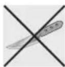
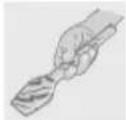
Donotusemetallicspongesorsharpscrapers:theywilldamagethe surface.
Useordinarynon-abrasiveproducts,togetherwithanti-scratch spongesandwoodenorplasticutensilsifnecessary.
Rinsethoroughlyanddrywithasoftclothorchamoisleather.
5.2Cleaningthecomponents
5.2.1 Knobs
Theknobsshouldbecleanedwithlukewarmwaterand washingupliquid.Foreasiercleaningtheycanberemovedby pullingthemupwards.Drythoroughlyaftercleaning.

Donotuseaggressiveproductscontainingalcoholorproductsforcleaningsteel andglasswhencleaningtheknobs,astheseproductscouldcausepermanent damage.
5.2.2 Racks
Removetheracksandcleanthemwithlukewarmwaterand non-abrasivedetergent,makingsuretoremoveany encrustations.Replacethemonthecookinghob. Thesecomponentsmustnotbewashedinthedishwasher.
5.2.3Flame-spreadercrowns
Theflame-spreadercrownsareremovable.Washthemwith hotwaterandnon-abrasivedetergent,makingsuretoremove anyencrustations.
Toremoveburnedonfoodresidue,leavetosoakinhotwater andwashingupliquid,thenscrubusingascourersponge. Forlessstubbornresidueandforpolishing,usestainless steelcreamcleanerCremalnoxwithamicrofibercloth. Aftercleaningensuretheyareperfectlydryandreposition themcorrectly.
5.2.4 Ignitersandthermocouples
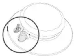
Forcorrectoperationtheignitersandthermocouplesmust alwaysbeperfectlyclean.Checkthemfrequentlyandclean themwithadampclothifnecessary.Removeanydry residueswithawoodentoothpickoraneedle.


5.2.5Lid(onsomemodelsonly)
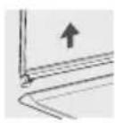
Cleantheglassorsteellid, wheremounted, withlukewarmwater. Never use abrasivespongesordetergents. Tocleantherearpartofthecooktop, remove thelidunitbyliftingitupwards.
When finished cleaning, refit the covermakingsuretoinsert it correctly.
Beforeliftingupthelid, dryoutanyliquidthatmayhavedripped.
Neverlowerthelidwhenburnersareonorstillhot.

Aftercleaning, drytheappliancethoroughlytopreventwaterordetergentdrips frominterferingwithitsoperationorcreatingunsightlymarks.
6. POSITIONINGINTHECOUNTERTOP

The following operation requires building and/or carpentry works must be carried out by a competent tradesman.
Installation can be carried out on various materials such as masonry, metal, solid wood or plastic laminated wood as long as they are heat resistant (T 90°C).
6.1 Fixingtothesupportingstructure
Createanopeningwiththedimensionsshowninthefigureinthetopsurfaceof thecounte.

A(mm)B(mm)C(mm)D(mm)E(mm)L(mm)X(mm)Y(mm)
| min 145 | min 460 | min 750 | 20÷40 | min 50 | 690 | 555÷560 | 478÷482 |
Carefullypositionthesuppliedinsulatingsealontheouterperimeterofthehole madeinthecountertopasshowninthefigurebelow,tryingtomakeitstickon theentiresurfacebyapplyinglightpressureonitwithyourhands.Refertothe dimensionsinthefigure,bearinginmindthatthesidesAmustbrushagainstthe hole. Fix the hob to the unit using the appropriate brackets B supplied.
Carefully trim the surplus away from edge C beyond the seal. The dimensions given in the following drawing refer from the hole to the inside of the seal.


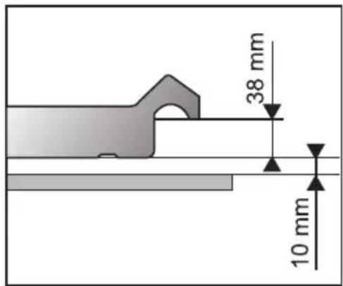
Incaseofinstallationonanemptykitchenunitwithdoors,aseparationpanel mustbeplacedunderthehob.Keepaminimumdistanceof10mmbetweenthe bottomofthehobandthesurfaceofthepanel,whichmustbeeasilyextractable toallowsufficientaccessforanytechnicalassistance.

7.ELECTRICALCONNECTION
Makesurethatthevoltageandcapacityofthepowerlineconformtothedata shownontheplatelocatedunderthecasing.Donotremovethisplateforany reason.

Theplugattheendofthesupplycableandthewallsocketmustbeofthesame typeandmustconformtotheapplicablelegislationonelectricalinstallations. Makesurethatthesupplylineissuitablyearthed.

Passthepowersupplycablethroughthebackoftheunit,takingcarethatit doesnottouchthebottomcasingofthehobortheoven(ifany)installed underneathit.

Fitthepowersupplylinewithamultipolarcut-outdevicewithacontactopening gapequaltoorgreaterthan3mminaneasilyaccessiblepositionclosetothe appliance.

Avoiduseofadaptersandshunts.

Ifthepowercableisreplaced, thecross-sectionofwiresinthenewcablemustbe nolessthan0.75mm 2 (3x0.75cable), rememberingthattheendforconnectionto theappliancemusthaveanearthwire (yellow/green)whichisatleast20mm longer.
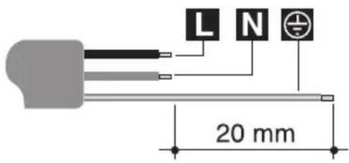
OnlyuseaH05V2V2-Forsimilarcableresistanttothemaximumtemperatureof 90°C . Thecablemustbereplacedbyaspecialisedtechnicianwhomustcarry outtheconnectiontothepowergridfollowingthediagrambelow.
L=brown
N = b l u e

=yellow/green

Thepowersupplycablemustbereplacedbyanauthorisedservicecentreto preventanyrisks.

Themanufacturerdeclinesallresponsibilityfordamagetopersonsorthings causedbynon-observanceoftheaboveprescriptionsorbyinterferencewith anypartoftheappliance.
8.GASCONNECTION
If the appliance is installed on an oven, you must avoid running the gastube round the back of the oven in order to avoid overheating.
Connectiontothegassupplynetworkcanbemadeusingarigidcopperhose oraflexiblesteelhosewithacontinuouswallandincompliancewiththe guidelinesestablishedbytheapplicablestandard.
Tofacilitatetheconnection,connectorAonthebackoftheappliancecanbe orientated laterally; loosen hexagonal nut B, twist connector A into the desired positionthenretightenhexagonalnutB(itissealedwitharubbergasket).Once theoperationiscomplete,checkthehosefittingsforleaksusingasoapy solution;neveruseaflame.
ThecookerhobispresetfornaturalgasG20(2H)atapressureof20mbar. For supplyingitwithothertypesofgas,seechapter"9.ADAPTATIONTO DIFFERENTTYPESOFGAS".Thegasinletconnectionisthreaded 1/2 "for externalgas(ISO228-1).
Connectionwitharigidcopperhose:The
connectiontothegassupplynetworkmustbemade insuchawaythatitdoesnotcausestressesofany typeontheappliance.
The connection can be made using the adapter unit D with double cone, always inserting gasket (provided) in between.
Connectionwithaflexiblesteelhose:useonly continuouswallstainlesssteelhosesthatcomply withtheapplicablestandards,makingsuretoalways insertgasketC(provided)betweenconnectorAand flexiblehoseE.
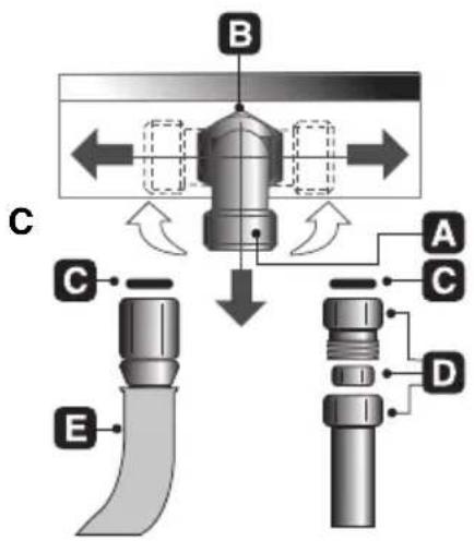

Installationwithflexiblehosemustbecarriedoutsothatthelengthofthepiping doesnotexceed2metreswhenfullyextended;makesurethatthehosesdonot comeintocontactwithmovingpartsandthattheyarenotcrushedinanyway.
8.1ConnectiontoLPG

Useapressureregulatorandmaketheconnectiononthegascylinderfollowing theguidelinesetoutintheregulationsinforce.
Makesurethatthesupplypressurecomplieswiththevaluesindicatedinthe paragraph"3.2Burnerandnozzlecharacteristicstables".
8.2 Roomventilation

Theroomcontainingtheapplianceshouldhaveanairsupplyinaccordancewith thestandardsinforce. Theroomwheretheapplianceisinstalledmusthave enoughairflowneededfortheregularcombustionofgasandthenecessaryair changeintheroomitself. Theairvents,protectedbygrills,mustbetherightsize tocomplywithcurrentregulationsandpositionedsothatnopartofthemis obstructed,notevenpartially.
Theroommustbekeptadequatelyventilatedinordertoeliminatetheheatand humidityproducedbycooking:inparticular,afterprolongeduse,youare recommendedtoopenawindowortoincreasethespeedofanyfans.
8.3 Extraction of the combustion products

Thecombustionproductsmaybeextractedbymeansofhoodsconnectedtoa naturaldraughtchimneywhoseefficiencyiscertainorviaforcedextraction.An efficientextractionsystemrequiresprecisionplanningbyaspecialistqualifiedin thisareaandmustcomplywiththepositionsanddistancesindicatedbythe regulations.Whenthejobiscomplete,theinstallermustissueacertificateof conformity.
9.ADAPTATIONTODIFFERENTTYPESOFGAS

Beforecarryingoutthefollowingoperations, disconnecttheappliancefromthe powersupply.
ThecookerhobispresetfornaturalgasG20(2H)atapressureof20mbar.If othertypesofgasaretobeused,thenozzlesmustbereplacedandtheprimary airmustbeadjusted.
Inordertoreplacethenozzlesandadjusttheburners,thehobtopmustbe removedasdescribedbelow.
9.1Removingthehobtop
1 Remove all the knobs, panstands, the caps and the flame spread crowns;
2removethescrewsandthenutsAthatsecuretheburnersupports;
3liftthehobtopfromitshousing;
4replacetheburnernozzlesinaccordancewiththereferencegaschart;
5adjusttheprimaryairasdescribedin"9.5Primaryairadjustment".

9.2 Adjustment for LPG
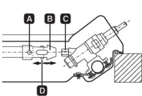
Loosen screw A and push support B all the way. Using a double head, remove nozzleCandreplaceitwiththeappropriatenozzle,followingtheinstructionsin thetablesforthetypeofgastobeused.Thenozzletighteningtorquemustbe no more than 3 Nm. Reposition support B so that nozzle C is covered perfectly. Move the Venturi tube D to adjust the air flow until distance "X" is reached indicatedinthechartinparagraph"5.5Primaryairadjustment"andthensecure thetubebymeansofscrewA.Aftertheadjustmentshavebeencarriedout, restorethesealswithsealingwaxorequivalentmaterial.

| Burner | Rated heating capacity (kW) | LPG-G30/G3128/37mbar | ||||||
| Nozzle diameter 1/100mm | By-pass mm 1/100 | Reduced capacity (W) | Capacity g/hG30 | Capacity g/hG31 | ||||
| Auxiliary (1) | 1.05 | 48 | 30 | 33 (*) | 380 | 76 | 75 | |
| Semi-rapid (2) | 1.65 | 62 | 30 | 33 (*) | 380 | 120 | 118 | |
| Medium rapid (3) | 2.55 | 76 | 37 | 40 (*) | 650 | 185 | 182 | |
| Large Rapid (4) | 3.1 | 85 | 43 | 750 | 225 | 222 | ||
| Ultra-rapid (5) | 3.3 | 87 | 55 | 65 (*) | 1200 | 240 | 236 | |
| Doublecrown | Internal (6) | 1.15 | 48 | 30 | 33 (*) | 380 | 84 | 82 |
| External (6) | 3.8 | 92 | 55 | 65 (*) | 1200 | 276 | 271 | |
| Fish burner (7) | 2 | 67 | 43 | 45 (*) | 750 | 145 | 143 | |
(*)By-passvalueforapplianceswithoutvalves.
9.3 Adjustment for city gas
Carryoutthesamestepsasdescribedin"9.2AdjustmentforLPG", butselectthe nozzlesandadjusttheprimaryairforcitygasasindicatedinthetablebelowandin "9.5Primaryairadjustment".
Warning: Only units with safety valves can be used with city gas G110.
| Burner | Rated heating capacity (kW) | Citygas-G1108mbar | ||
| Nozzlediameter 1/100mm | Reducedcapacity (W) | |||
| Auxiliary(1)1.05132380 | ||||
| Semi-rapid(2)1.65165380 | ||||
| Mediumrapid(3)2.55210650 | ||||
| LargeRapid(4)3.1240750 | ||||
| Ultra-rapid(5)3.3250 | 1200 | |||
| Doublecrown | Internal(6) | 1.05132380 | ||
| External(6) | 3.9290 | 1200 | ||
| Fishburner | 2 | 190750 | ||
The values for city gas refer to appliances in category III 1a2H3+.
9.4 Adjustmentfornaturalgas
The hob is preset for natural gas G20 (2H) at a pressure of 20 mbar. To reset the applianceforoperationwiththistypeofgas,carryoutthesamestepsasdescribed in"9.2AdjustmentforLPG",butselectthenozzlesandadjusttheprimaryairfor naturalgasasindicatedinthetablebelowandin"9.5Primaryairadjustment".After the adjustments have been carried out, restore the seals with sealing wax or equivalentmaterial.
| Burner | Rated heating capacity (kW) | Naturalgas-G2020mbar | ||
| Nozzlediameter 1/100mm | Reducedcapacity (W) | |||
| Auxiliary(1)1.0573 | 380 | |||
| Semi-rapid(2)1.6592 | 380 | |||
| Mediumrapid(3)2.55115650 | ||||
| LargeRapid(4)3.1126750 | ||||
| Ultra-rapid (5) | 3.3130 | 1200 | ||
| Double crown | Internal(6) | 1.0573 | 380 | |
| External(6) | 3.9140 | 1200 | ||
| Fishburner | 2 | 100750 | ||
9.5 Primaryairadjustment
Referstodistance“X” in mm.

| BURNER | G30/G3128/37mbar | G2020mbar | G1108mbar | |
| Auxiliary(1)1.01.50.5 | ||||
| Semi-rapid(2)1.51.50.5 | ||||
| Mediumrapid(3)1.51.01.0 | ||||
| LargeRapid(4)10.02.51.5 | ||||
| Ultra-rapid(5)2.52.01.5 | ||||
| Doublecrown | Internal(6)6.03.01.0 | |||
| External(6)10.03.05.0 | ||||
| Fishburner | 2.52.01.0 | |||
To identify the burners on your hob, refer to the drawings in "9.7 Arrangement of the burners on the cookinghob".
9.6Finaloperations
After making the adjustments described above, reassemble the appliance by followingtheinstructionsin"9.1Removingthehobtop"inreverseorder.
9.6.1 Adjusting the minimum for city and natural gas
Reposition the components on the burner and slidetheknobsontothetaprods.
Light the burner and set it on the minimum position. Extract the knob again and turn the adjustment screw inside or next to the tap rod (depending on the model) until the correct minimumflameisachieved.
Refittheknobandverifythattheburner flameis stable (when turning the knob rapidly from the maximumtotheminimumpositiontheflamemust notgoout).

9.6.2AdjustingtheminimumsettingforLPG
ToadjusttheminimumsettingwithLPG,youmusttightenthescrewinsideornextto thetaprod(dependingonthemodel)fullyinaclockwisedirection.
Thebypassdiametersforeachindividualburnerareshownintable"9.2Adjustment forLPG".

Afteradjustmentwithagasotherthanthepresetone,replacethelabelonthe casingoftheappliancewiththelabelcorrespondingtothenewgas. Thelabelis insertedinsidethepacktogetherwiththenozzles.
9.7 Arrangement of the burners on the cooking hob
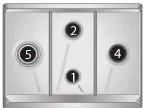
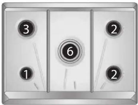
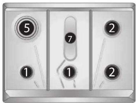
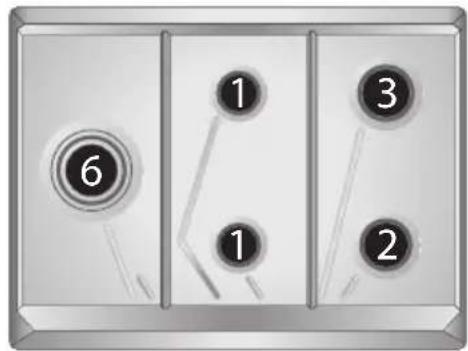


BURNERS
1.Auxiliary
2.Semi-rapid
3. MediumRapid
4.LargeRapid
5.Triplecrownultra-rapid
6. Doublecrownultra-rapid
7.Fishburner
9.8 Lubrication of gastaps

Overtimethegastapsmaybecomedifficulttoturnandgetblocked.Cleanthem internallyandreplacethelubricationgrease.
Thisprocedure must be carried out by as specialised technician.
- INSTRUCTIONSFORUSE
- SAFETYPRECAUTIONS
- ENVIRONMENTAL RESPONSIBILITY
- OURENVIRONMENTALCARE
- YOURENVIRONMENTALCARE
- USINGTHEHOB
- LIGHTINGTHEBURNERS
- PRACTICALTIPSFORUSINGTHEBURNERS
- PANDIAMETERS
- USING THE GRIDDLE PLATE
- CLEANINGANDMAINTENANCE
- CLEANINGTHEHOB
- ORDINARYDAILYCLEANING
- FOODSTAINSORRESIDUES
- CLEANINGTHECOMPONENTS
- KNOBS
- RACKS
- FLAME-SPREADERCROWNS
- IGNITERSANDTHERMOCOUPLES
- LID(ONSOMEMODELSONLY)
- POSITIONINGINTHECOUNTERTOP
- FIXINGTOTHESUPPORTINGSTRUCTURE
- ELECTRICALCONNECTION
- GASCONNECTION
- CONNECTIONWITHARIGIDCOPPERHOSE:THE
- CONNECTIONTOLPG
- ROOMVENTILATION
- EXTRACTION OF THE COMBUSTION PRODUCTS
- ADAPTATIONTODIFFERENTTYPESOFGAS
- REMOVINGTHEHOBTOP
- ADJUSTMENT FOR LPG
- ADJUSTMENT FOR CITY GAS
- ADJUSTMENTFORNATURALGAS
- PRIMARYAIRADJUSTMENT
- FINALOPERATIONS
- ADJUSTING THE MINIMUM FOR CITY AND NATURAL GAS
- ADJUSTINGTHEMINIMUMSETTINGFORLPG
- ARRANGEMENT OF THE BURNERS ON THE COOKING HOB
- BURNERS
- LUBRICATION OF GASTAPS
Brand : SMEG
Model : SR775AX
Category : Cooker