USER MANUAL LASER FF 55 ZIBRO
Congratulations with your purchase of the Zibro, the number one brand among movable heaters. You have purchased a first-class quality product, which will serve you for many years to come. This, of course, provided you use the heater correctly. Please read these Directions for Use first, to ensure maximum lifetime for your Zibro.
Your heater comes with a 24-month manufacturer's warranty on all defects in material or workmanship.
We wish you much warmth and comfort with your Zibro.
Yours sincerely,
PVG International B.V.
Customer Service Department
1 READ THE DIRECTIONS FOR USE FIRST.
2 IN CASE OF ANY DOUBT, CONTACT YOUR ZIBRO DEALER.
SUMMARY
Chapter 1: INSTALLATION
Chapter 3: ERROR MASSAGES
Chapter 4: WARRANTY PROVISIONS
WHAT YOU NEED TO KNOW IN ADVANCE
THE RIGHT FUEL
Only use Class C1 paraffin fuel in accordance with BS2869: Part 2, or equivalent. Your Zibro heater has been designed for use with high-quality water-free pure paraffin oil, such as Zibro Extra or Zibro Kristal. Only fuels of this kind will ensure clean and proper burning. Lower quality fuel may result in:
increased possibility of malfunctioning
incomplete burning
reduced heater lifetime
smoke and/or smells
deposits on the grid or mantle
Using the right fuel is therefore essential for safe, efficient, and comfortable use of your heater.
Always refer to your local Zibro dealer for the right fuel for your heater.

- The first time you ignite your heater it will smell like 'new' for a short time.
- Store your fuel in a cool and dark place.
- Fuel has a limited shelf life. Start every heating season with renewed fuel.
- The right quality of fuel will be assured, when you use Zibro Extra or Zibro Kristal for your heater.
- If you change to another brand and/or type of parrafin oil, you must first finish up all the remaining fuel in the heater.
TIPS FOR SAFE USE
1 Make sure that children are always aware of the presence of a burning heater.
2 Position the front of the heater at a distance of minimum 1.5 metres from walls, curtains, and furniture.
3 Do not use the heater in dusty rooms. You will not have optimum burning in such rooms. Do not use the heater in the immediate surrounding of a bath, a shower or a swimming pool.
4 Switch off the heater, before you leave or go sleeping. Unplug the heater as well, when you go away for a longer period of time (e.g. holidays).
5 Store and move fuel only in suitable tanks and jerrycans.
6 Make sure that the fuel is not exposed to heat or extreme temperature changes. Always store the fuel in a cool, dry and dark place (sunlight will affect the quality).
7 Never use the heater in places where harmful gasses or fumes may be present (e.g. exhaust gasses or paint fumes).
8 Beware that the grid of the heater becomes hot. If the appliance is covered there is a risk of fire.
9 Use only in accordance with state and/or local regulations, ordinances and codes.
10 Make sure the heater is on a level surface during operation
11 Do not service or refuel heater while in operation or still hot.
12 Do not operate in areas exposed to flammable vapors or high duel level to avoid fire or explosion.
Chapter 1, INSTALLATION
1. Introduction
This chapter contains all the relevant information, specifically:
Installation specifications
- List of installation tools
- Instructions for the installation of the Laser System
The heater can be installed at any location, on condition that there is full compliance with electrical, fuel and emission regulations.
Before you start installing the heating system (possibly including electrical wiring and fuel supply equipment), check the local building and fire safety regulations. The requirements stipulated in these regulations must be respected in order to guarantee a legally approved installation and correct operation.

The heater was designed to be used to a maximum altitude of 1000m above sea level. Contact your dealer for the necessary adjustments if you wish to use it at a higher altitude.
2. Moving the heater
In addition to the space required for the heater, extra room must be kept free for air circulation. We recommend that you store fuel elsewhere. The Laser System can be placed on any type of flooring (including fitted carpets or other flammable materials) and operate safely, unless fuel or fire safety regulations specify otherwise. Check the gaps in the manner stipulated in the instructions in the manual.
- Crosshead screwdriver
- Steel tape measure
- Felt-tip pen or pencil
- Cement for exterior use
- Electric drill (clockwise and anti-clockwise recommended)
- Hole cutting saw, jig saw or other tools suitable for sawing a hole of 70 80 ~mm for the exhaust pipe
- Long drill
- Standard screwdrivers
- Volt, Ohmmeter
- Spirit level
- Small range of self-tapping screws
- Insulated screwdriver
- Protective material for your floor
- Container for fuel exhaust pipe
3. The electrical supply system
The electrical system must be protected from overloads by an at least 5-Ampere fuse or contact breaker.

Some installations (such as for use in mobile homes) must be fitted with a permanent connection to the household power circuits. This must be done by a recognised electrician.
Chapter 1, INSTALLATION
4. Wiring for the room temperature sensor
A temperature sensor that can be fitted to a wall measures the room temperature in order to automatically regulate the heating. The standard sensor wire is approximately 2.5m long.

The sensor may not be placed in a draught, direct sunlight or the warm air flowing out of the heater. This may cause incorrect temperature indications.
5. Unpacking
Save all packaging materials for possible future transportation.
A) Remove the cardboard (drilling) template and the user's manual from the packaging.
B) Remove the box with the installation kit from the packaging.
C) Remove the heater from the packaging.
D) Remove the plastic bag containing the parts.
E) Remove the exhaust pipe from the bottom of the box.
F) Check that all parts are present.

Only the standard feed and exhaust system is supplied with the heater.
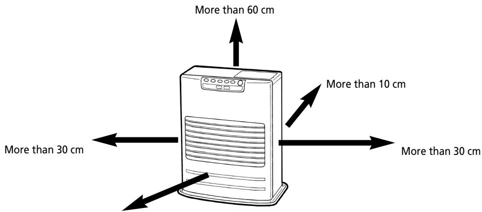
More than 1.5m
Laser FF 55
Fig. 1-1: Gaps heater/exhaust pipe
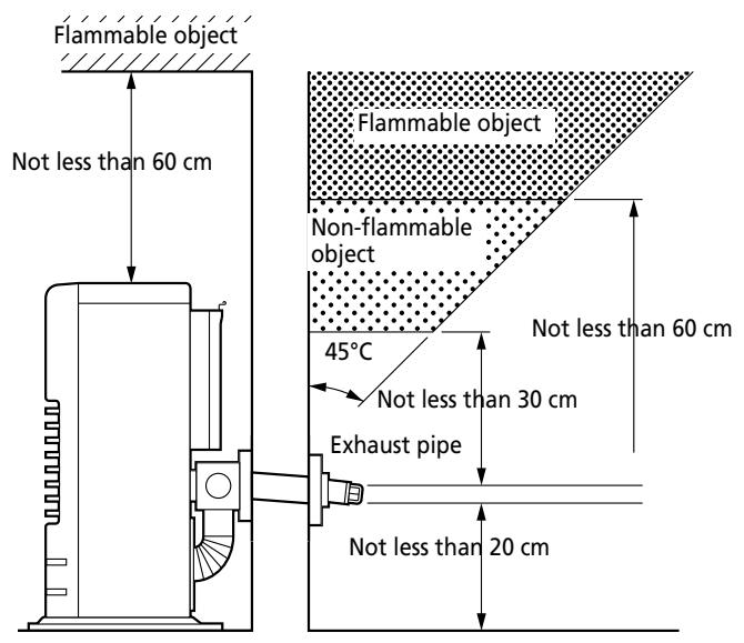
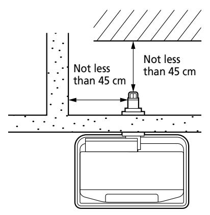
Fig. 1-1 (continued) gaps heater/exhaust pipe
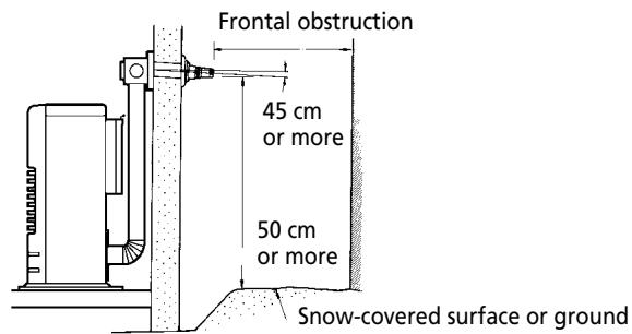
Important: The gap with the ground must be enlarged in areas subject to heavy snowfall.
Important: A windbreaker may be necessary in open areas that are subjected to strong winds.
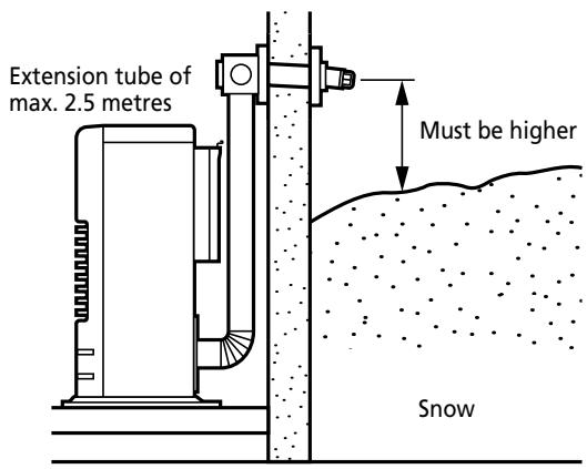
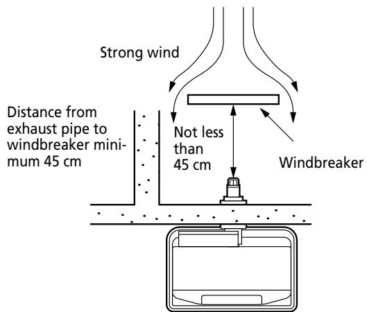
Fig. 1-2 Gaps heater/exhaust pipe
Chapter 1, INSTALLATION
After using the installation template as a guide for the drilling of the hole for the exhaust pipe, the Laser can be installed normally, according to the procedure in the illustration.
If the template is lost or the heater has to be moved, these are the dimensions and locations of the holes for the fuel pipe and exhaust pipe.
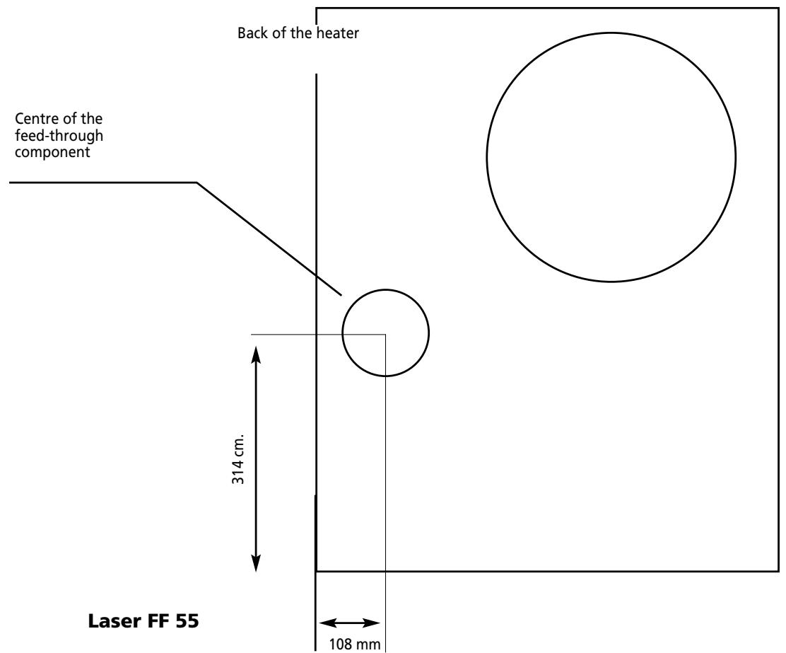
Fig. 1-3 Template

Do not remove any components from the heater. Always contact your dealer if repairs are required.
If the electricity cable is damaged, this may only be replaced with type H05 VV-F and by a recognised installer.
Chapter 1, INSTALLATION
Standard installation parts
The following list of standard installation parts is supplied with your heater. It may be necessary to order extra parts from your Zibro dealer if other installation methods are required.
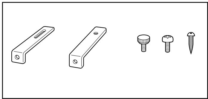
Wall hooks (2 set)
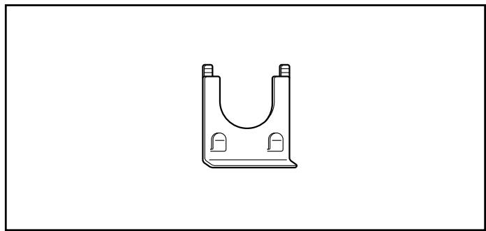
Pipe holder (1)
Pipe lock (1)
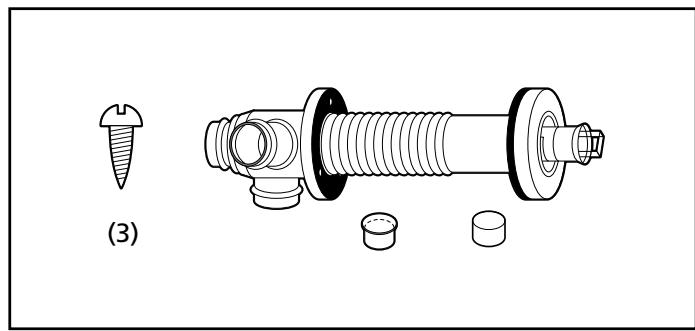
Exhaust pipe (1)
Chapter 1, INSTALLATION
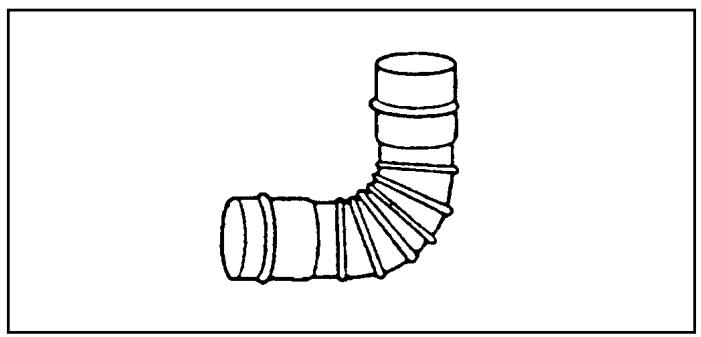
Right-angled exhaust pipe bend (1)
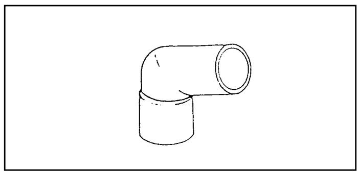
Right-angled air hose (2)
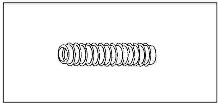
Flexible air hose (1)
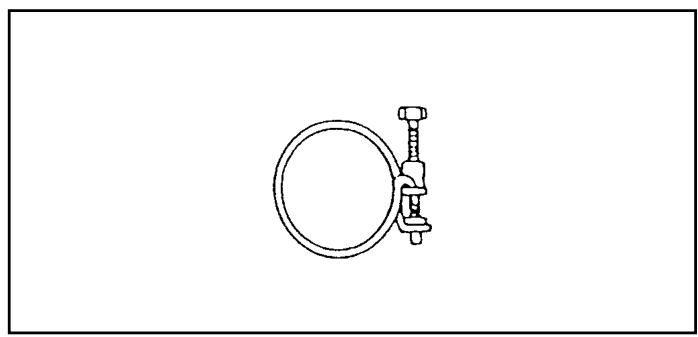
Hose clip (2)
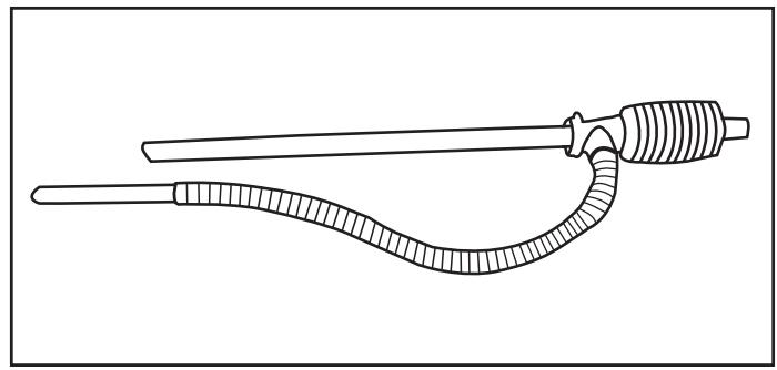
Manual fuel pump (1)
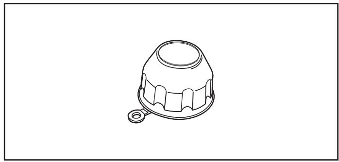
Fuel cap cover (1)
Chapter 1, INSTALLATION
- For the standard installation, use the template supplied to position the hole for the exhaust pipe correctly.
Use cellotape or small nails to attach the template to the desired position on the wall (see Fig. 4).
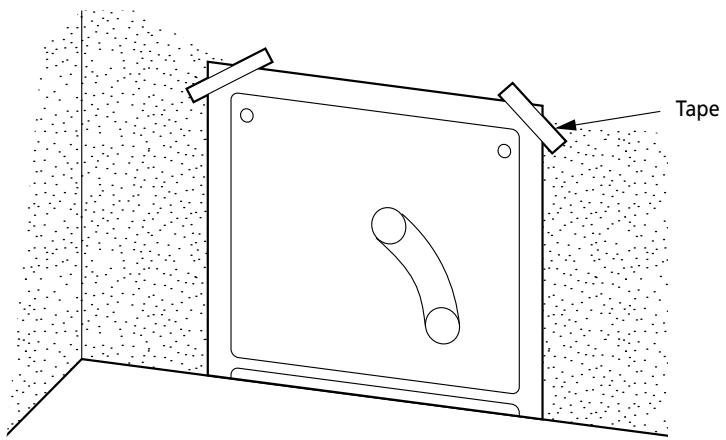
Fig. 4
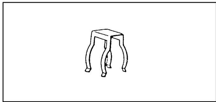
Comment: The heater must be installed on a strong and stable floor. The floor must be flat and level. If this is not the case, the heater can be levelled by means of adjustable legs. This can be checked with the plumb line.
- Drill the hole for the exhaust pipe. Use a hole saw with a diameter of 70 80 ~mm (see Fig. 5). The opening on the interior side of the wall must be a little higher than the opening on the outside in order to create a slight gradient in the feed-through and exhaust pipe
after installation (approximately 2^ ) (see Fig. 6). This ensures that condensed water in the exhaust pipe flows to the outside and prevents the penetration of rainwater and snow after installation.
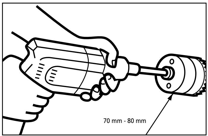
Fig. 5
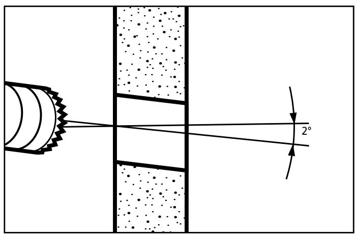
Fig. 6
Chapter 1, INSTALLATION
3. Install the inner flue pipe.
a. For wall thickness 230 320mm
From inside the room, insert the inner flue pipe through the hole. Make sure the arrow on the inner flue pipe is pointing up. Secure the inner flue pipe to the wall with the three wood screws. (See Fig. 7)
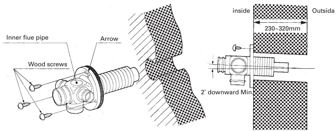
Fig. 7
b. For wall thickness 130 230mm
Remove Intake joint and Exhaust joint from Outer flue pipe (See Fig. 8).
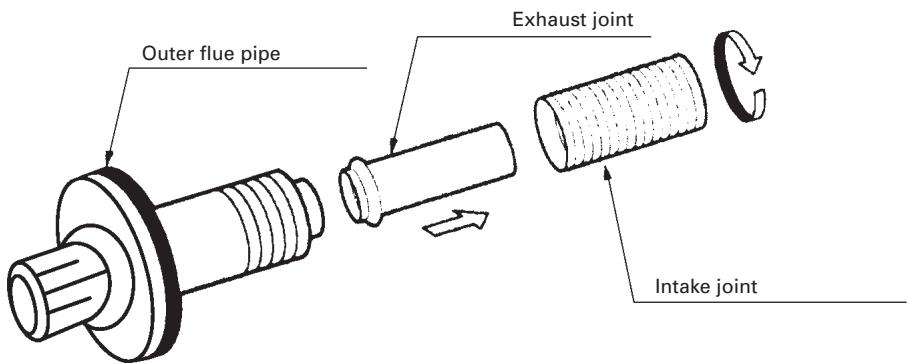
Fig. 8
Chapter 1, INSTALLATION
c. From outside, insert the outer flue pipe through the hole. Secure the outer flue pipe to the wall by turning it clockwise. This locks the two halves together (See Fig. 9).
IMPORTANT: Make sure the arrow on the outer flue pipe fringe is pointing up.
Make sure to secure the outer flue pipe well. (A-part shown in Fig. 9)
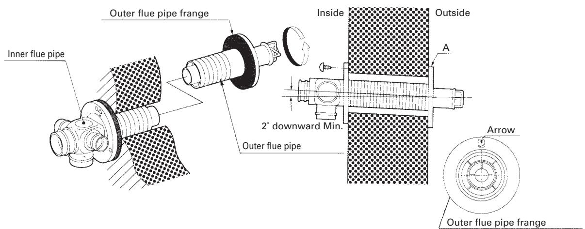
Fig. 9
- Attach the right-angled exhaust pipe bend to the outlet of the exhaust pipe. Cut, if necessary, the flexible air hose to size. Fasten the right-angled air hose to both ends of the flexible air hose – now attach the right-angled air hose to the inlet of the exhaust pipe. Attach the right-angled air hose to both ends of the flexible air hose. Now fasten the right-angled air hose to the inlet of the exhaust pipe.
Fasten the right-angled air hose onto the inlet with a hose clip. Seal the inlets and outlets that are not being used with the caps supplied. Check that the caps are firmly in position (See Fig.10). Use water or soap pads to provide lubrication when fitting the right-angled air hose onto the flexible air hose. The total length of the exhaust pipe may be a maximum of 3m (max. 3 bends).
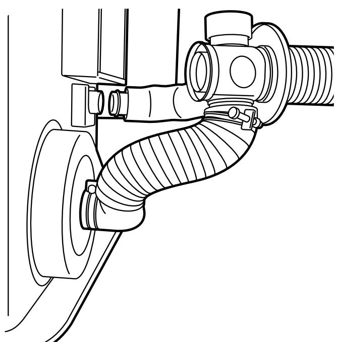
Fig. 10
Chapter 1, INSTALLATION
- Move the heater into position. Attach the right-angled exhaust pipe bend to the outlet of the exhaust pipe and attach the right-angled exhaust pipe bend to the inlet. Make sure all connections are tight (See Fig. 11).
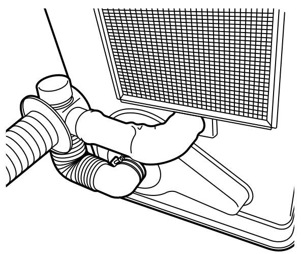
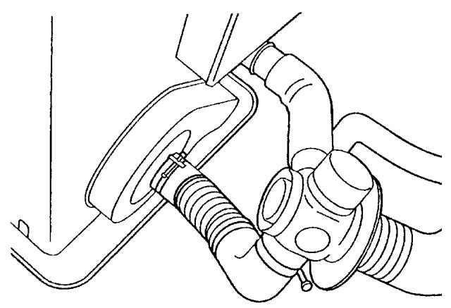
Fig. 11
- Fasten the right-angled air hose to the inlet with the hose clip. Attach the right-angled exhaust bend to the exhaust pipe with the pipe holder (If the extension pipe is used, also attach the pipe holder to the connection of the right-angled exhaust pipe bend and extension
pipe). Attach the right-angled exhaust bend to the outlet by sliding the pipe lock into the outlet clip (See Fig. 12).
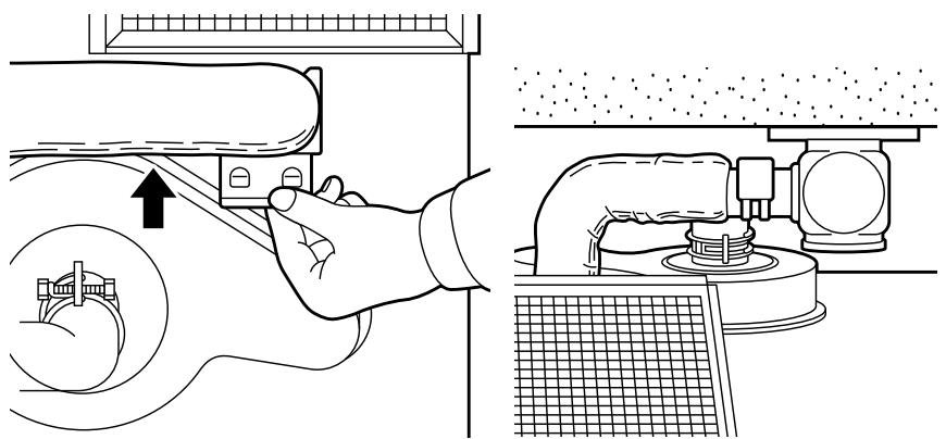
Fig. 12
Chapter 1, INSTALLATION
CHECKLIST
- Check whether the heater has been connected to a suitable socket.
- Ensure that the fuel is free of water or other contaminants.
- Check outside the building in order to ascertain that there is no fuel or obstructions to the free circulation of air in the area immediately adjacent to the exhaust pipe.
- Inspect the inlet air hose for cracks, loose connections or blockages.
- Check the outlet air hose for cracks, loose connections or blockages.
- Check the back of the heater to ensure that the airflow to the air circulation ventilator is not obstructed.
- Inspect the interior of the building to ensure that the area immediately adjacent to the heater is free of fuel and objects that may obstruct the free flow of air.
- Check that the room sensor is not exposed to draughts, direct sunlight or heat radiated directly from the heater.
- Use a spirit level to check that the heater is level.
If this inspection brings any faults to light, resolve these problems before using the heater.

Use only water-free high quality pure paraffin oil. Never use benzene, LPG, camping gas or other flammable liquids. The use of these substances may cause explosions or fire.
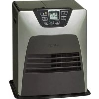
The Laser is an easy to use ventilated petroleum heater. It provides considerable quantities of heat, automatically regulates the room temperature, uses very little fuel and electricity and has options for automatic or manual operation.
This chapter provides all the information required for the operation of the Laser heater system. All specified operating procedures must be carried out in the order in which they are described.
2. Laser FF 55 heater specifications
| Low | Medium | High |
| Heat yield (W) | 1590 | 3550 | 5500 |
| Fuel consumption (l/h) | 0.18 | 0.401 | 0.623 |
Nominal yield
(as applied to petroleum heaters): 92.7%
Power consumption:
| Setting | Setting | Setting | Setting |
| Ignition | high | medium | low | off |
| 275 W | 51 W | 40 W | 31 W | 4 W |
Ventilator capacity: 5.2 / 3.4 / 1.5 cubic metre/min.)
- Fuel source: removable tank of 7.6 litres or external tank
Heating air as main heat source: 65 - 220m^3
3. Operating elements and lights
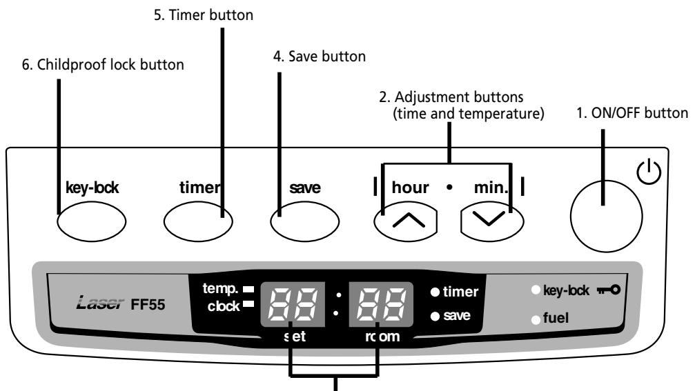
3. Information display
Fig. 2-1 Operation panel
- ON/OFF button:
The main switch to turn the heater on and off.
Switch it "ON" to activate the heater. Combustion will start after a 3-9 minutes pre-heating period. The heater has 4 settings "HIGH", "MEDIUM", "LOW" and "OFF".
- Adjustment buttons:
Temperature selection switches offer the user the option to select the desired temperature during operation.
- Information display
Displays the clock, set temperature, room temperature and error codes.
- SAVE button:
Allows you to limit the temperature.
When this function is activated, the heater will automatically switch off and on again.
- TIMER button:
Allows you to switch on the heater automatically at a preset time.
- CHILDPROOF LOCK button:
Can be used to prevent children accidentally changing the heater settings.
Step 1: Filling fuel

- Do not fill the removable tank in the living room, but in a more suitable place (there can always be some spillage).
- Do not refuel the heater while in operation or still hot.
Follow the procedure below:
[1] Make sure that the heater is switched off.
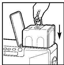
[2] Open the tank lid and lift the removable tank out of the heater.
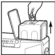

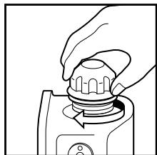
Note: Some drops may leak from the tank. Put down the removable tank (cap pointing upwards) and screw off the fuel cap using the fuel cap cover.
[3] Take the manual fuel pump and insert the smooth, most rigid tube into the jerry can. Make sure that it is in a higher position than the removable tank. Insert the ribbed hose into the opening of the removable tank.
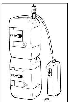
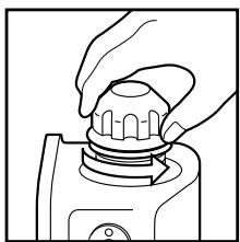
[4] Lock the switch button on top of the pump (turn clockwise).
[5] Squeeze the pump a few times, until fuel starts flowing into the removable tank. As soon as this happens, there is no need to press any longer.
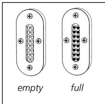
[6] Check the removable tank fuel gauge while filling the tank. Stop filling by loosening the switch button on top of the pump (turn anti-clockwise), once the gauge indicates that the tank is full. Never overfill the tank, especially not when the fuel is very cold (fuel expands when it heats up).
[7] Let the remaining fuel in the pump flow back into the jerry can and carefully remove the pump. Carefully screw the fuel cap back on the tank using the fuel cap cover. After use, re-store the cover at the rear of the heater. Clean off any spilled fuel.
[8] Check whether the fuel cap is straight and tightened properly. Reinstall the removable tank in the heater (cap down). Close the tank lid.
Step 2: Plug in the heater
Insert the plug into the wall-socket (230 Volts - AC/50Hz).
Step 3: Setting the clock
Important: The clock on the heater must always be set to the correct time.
It is only possible to set the correct time, when the heater is connected to the mains and not burning. Use the adjustment buttons to set the time. First press either of the two buttons to switch on the
function (the CLOCK light and the information display will start blinking). Next, set the hours using the button on the left ( hour) and the minutes using the button on the right ( min.). Press once to increase the value by one step. When you hold down the button, the value will continue going up, until you release the button again. After approximately 10 seconds the blinking will stop and the setting will be locked. After switching off the heater, the clock time will be displayed.
5. Igniting the heater
The heater is operated directly by the user. However, the heat yield is controlled automatically in accordance with the room temperature registered by the temperature sensor.
Step 1: Switch the heater ON
Press the ON/OFF button. The current room temperature and the set temperature are displayed on the information display.
The ON/OFF light starts to flash, after which the heater will switch on.

Note: (*) The start-up time depends on the room temperature.
After 9-15 minutes, the heater will automatically select the correct operating mode and the ON/OFF button will now be illuminated continuously.
Room temperature:
under 0^ C
11 minutes
0^ - 15^
9 minutes
15°C
8.5 minutes
If no flames are visible after the start-up period, the heater will deactivate and then restart automatically. If flames are still not detected, the heater will deactivate and will have to be restarted manually (error code E-2 on the information display).
Step 2: Setting the room temperature
The temperature setting can only be adjusted, when the heater is burning. Use the adjustment buttons to adjust the temperature. First press either of the two buttons to switch on the function (the TEMP light next to the information display will start blinking). Next, adjust the tem
perature using the button on the right ( min.) to set the temperature to a higher setting and the button on the left (△ hour) to lower the temperature. Press once to increase the value one step. After approximately 10 seconds the light will stop blinking and setting will be locked. The available temperature settings range from 10^ minimum to 32^ maximum. When the heater has been unplugged (or after a power failure), the temperature will reset to the factory setting of 20^ .
The operating mode is automatically controlled in accordance with the room temperature detected by the room temperature sensor. The heater works in the "HIGH" operating mode until the room temperature has reached the desired level.
When the room temperature reaches the chosen setting, the heater automatically switches to the "MED" or "LOW" operating mode in order to maintain the desired temperature.
Step 3: The correct use of 'SAVE'
The 'SAVE' function allows you to limit the temperature. When this function is activated, the heater will automatically switch off, when the room temperature exceeds the set temperature by 2^ . Subsequently, when the room temperature has dropped again to the set temperature, the heater will automatically switch on again. Activate the 'SAVE' setting by pressing the appropriate button. The SAVE indicator light will light up. Switch off the function by pressing the SAVE button once again.

Without the 'SAVE' setting your heater will maintain the set temperature by approximation as well, by adjusting its heating capacity. 'SAVE' is an economy setting, which you can use when, for instance, you are not present in the room or to keep it frost-free.
Step 4: The 'FUEL' indicator light
When the FUEL indicator light lights up, it means that there is only fuel left for 10 more minutes. The countdown of the remaining heating time can be seen in the information display. You remove the fuel tank and refill it outside the living room. If you don't refill it, you will hear an alarm signal every two minutes, warning you to refill the removable tank and after 10 minutes the heater will switch off automatically.
The timer allows you to switch on the heater automatically at a preset time.
In order to switch on the timer, the correct time must have been set and the heater should be off. Follow the procedure below:
[1] Press the TIMER button. The TIMER light and the information display will start blinking.
[2] Use the adjustment buttons to set the time at which the heater must ignite. Use the button on the left (△hour) to set the hours and the button on the right (▼min.) to set the minutes (interval of 10 minutes).
[3] Press the ON/OFF button while the information display is blinking.
[4] After approximately 10 seconds the information display will show CLOCK again and the TIMER indicator light will light up, indicating that the timer function has been activated.
To clear the timer setting, press the ON/OFF button once.

Note: When the room temperature is less than 15^ C , the preset time is changed automatically depending on the room temperature in order to heat the room by the desired time.
Room temperature
Ignition time
More than 15^ C
Set time
0^ C 15^ C
10 minutes before set time
Less than 0^
20 minutes before set time
7. Room temperature sensor
The room temperature sensor is fitted with a 2.5 meter cable. This is located on the back of the heater. Ensure that the cable does not touch the outlet tube. The room temperature sensor can be installed with cello tape or with a wood screw.
Select the location where the sensor is to be installed in such a way that it will not be exposed to direct sunlight, draughts or the warm air flowing out of the heater.
8. Childproof lock
The childproof lock can be used to prevent children accidentally changing the heater settings. When the heater is burning and the childproof lock is on, the heater can only be switched off. Other functions are blocked then. If the heater has already been switched off, the childproof lock also prevents accidental ignition of the heater. Activate the childproof lock by pressing the appropriate button and holding it down for more than 3 seconds. The KEY-LOCK indicator light will light up, indicating that the childproof lock has been activated. Switch off the childproof lock by pressing the button and holding it down for more than 3 seconds once again.
9. Switching off the heater
There are two ways to switch off the heater.
[1] Press the ON/OFF button. The information display will show the CLOCK signal. The air circulation ventilator and the ventilator motor continue to operate for approximately 3 minutes in order to cool the heater down.
[2] Press the TIMER button, when you want to switch off the heater and ignite it again with the timer the next time. This not only switches off the heater, but it also activates the timer function. You can change the required time with the adjustment buttons.
10. Recovery after overheating
The heater is protected against damage caused by overheating.
A sensor will activate if the temperature in the housing exceeds 80^ .
Step 1: Switch the heater OFF.
Step 2: Allow the heater to cool down.
Ensure that the metal housing has cooled sufficiently before touching it.
Under normal conditions, a period of 30 to 45 minutes is sufficient to allow the heater to cool down completely.
Step 3: Pull the heater plug out of the socket.
Step 4: Look for the source of the overheating. Overheating is usually caused by objects that obstruct the free flow of air. Check that the circulation ventilator or exhaust pipes are not blocked. Check that there are no objects blocking the outlet system.
Step 5: Remove the front panel.
Step 6: Clean the inside of the heater.
Before starting to clean the heater, ensure that the interior is cool enough to touch. Wipe all dust off the outside of the housing with a clean, non-fluffy, damp cloth or another suitable cleaning aid. Do not forget to clean the outside of the heat chamber and the heat exchanger.
Step 7: Re-attach the front panel.
Step 8: Insert the heater plug into the socket.
Step 9: Switch the heater ON.
Step 10: Re-program the heater (clock and timer).

Attention: If the heater overheats after the completion of a recovery procedure, contact your dealer and do not switch the heater on until the problem has been resolved.
11. Cleaning the filter (monthly)
Switch off the heater and let it cool down, before you start any maintenance work. Also disconnect the plug from the mains.
Your Zibro needs hardly any maintenance. It is, however, important that you clean the air filter with a vacuum cleaner and the grid with a damp cloth, both on a weekly basis.
Regularly inspect the fuel filter as well:
[1] Remove the removable tank from the heater and remove the fuel filter. Some drops may leak from the filter; keep a cloth at hand.
[2] Remove the dirt by tapping the fuel filter upside-down against a hard surface. (Never clean it with water!)
[3] Reinstall the fuel filter into the heater.
We recommend that you remove dust and stains in time with a damp cloth, because otherwise these may cause stains that are hard to remove.

Do not remove any heater components yourself. Always contact your Zibro dealer for repairs. When the power cord is damaged, it may only be replaced by an authorized fitter. Use a new cord of the type H05 VV-F.
12. Before consulting an expert
The following situations do not indicate defects.
While switching the heater on or off.
White smoke can be seen when the heater is switched on for the first time.
Machine oil or dust on the burner chamber or heat exchanger is burning.
The flames flicker for several minutes after the heater has been ignited.
The ignition rod continues to function when the heater is cold, even several minutes after ignition. This may cause the flames to be a little larger.
The heater makes intermittent creaking sounds when warming up or cooling down.
Expansion and shrinkage of metal parts may cause a slight creaking sound.
Circulation of air in the room does not start immediately when the heater is lit.
To prevent unpleasant cold draughts, the ventilator only switches on when the heater has become warm.
A loud clicking sound can be heard during the first use or when the fuel runs out.
There is air in the fuel pump. This should be gone within approximately 1 minute.

Note: The fuel pump may make a slight ticking sound during normal operation. This does not indicate a problem.
While the heater is in operation
A part of the burner pot and/or heat exchanger becomes red in color during operation.
This is normal and does not indicate a problem.
Chapter 3, ERROR MESSAGES
| CODE | INFORMATION | WHAT TO DO |
| E-0 | Power interrupted. | Re-ignite the heater |
| E-2 | Ignition safety feature is activated. | Contact your dealer |
| E-6 | Extinguished during operation. | Contact your dealer |
| E-8 | Blower motor malfunction. | Contact your dealer |
| E-12 | Overheating safety feature is activated. | Clean the air filter and remove dust. |
| E-13 | Burner thermistor malfunction | Contact your dealer |
| Excess fuel in the burner | Contact your dealer |
| E-22 | Ignition failure three times | Contact your dealer |
| --:-- | No fuel. | Refill removable tank. |
| Timer is not setting. | Set the timer. |
| Hi | Room temperature is higher than 35°C. | Check the position of room temperature sensor. |
| Position of room temperature sensor is not correct. | |
| Lo | Room temperature is lower than -10°C. | Check the position of room temperature sensor. |
| Room thermistor malfunction or disconnected. | |
Chapter 1, INSTALLATION
Your heater comes with a 24-months warranty starting on the date of purchase. Within this period all defects in material or workmanship will be repaired without any charge. The following provisions shall apply regarding this warranty:
1 We expressly dismiss all other claims for damages, including consequential damages.
2 Any repairs or replacements of components within the term of warranty will not result in an extension of the term of warranty.
The warranty shall no longer apply, when the heater has been modified, non-original parts have been used, or when it is repaired by third parties.
4 The warranty shall not apply to parts that are subject to normal wear, such as the burner mat and the manual fuel pump.
5 The warranty shall only apply, when you present the original, dated proof of purchase, provided no changes have been made to it.
The warranty shall not apply to damages caused by actions not in compliance with the Directions for Use, neglect, and the use of an incorrect type of fuel, or fuel past its use-by date. The use of incorret fuel can even be dangerous*.
7 Transportation costs and the risks involved during the transportation of the heater or heater components shall always be for the account of the purchaser.
In order to avoid unnecessary costs, we recommend that you always read the 'Directions for Use' carefully first. In case they offer no solution, please take the heater to your dealer for repair.
- Highly inflammable substances may induce uncontrollable burning, causing flames to break out. Should this happen, never try to move the heater, but always switch off the heater immediately. In case of emergency you may use a fire extinguisher, but only a type B extinguisher: a carbon dioxide or powder extinguisher.
Waste electrical products should not be disposed with household waste. Please recycle where facilities exist. Check with your local authority or retailer for recycling advice.
DISTRIBUTED IN EUROPE BY PVG INTERNATIONAL b.v.
A OSTERREICH
email: appliance@appliance-group.com
ESPAN
PVG Espana S.A.
Pol. Ind. San José de Valderas II
email: appliance@appliance-group.com
GB UNITED KINGDOM
Scott Brothers Ltd.
The Old Barn, Holly House Estate
Cranage, Middlewich, CW10 9LT UK
tel.: +44 1606 837787
fax: +44 1606 837757
email: sales@scottmail.co.uk
ITALIA
PVG Italy SRL
Via Niccolò Copernico 5
50051 CASTELFIORENTINO (FI)
tel: +39 571 628 500
fax: +39 571 628 504
email: pvgitaly@zibro.com
NORGE
Appliance Norge AS
Vogellunden 31
1394 NESBRU
tel: +47 667 76 200
fax: +47 667 76 201
email: appliance@appliance-group.com
NEDERLA
PVG International B.V.
P.O.Box 96
5340 AB OSS
tel: +31 412 694 694
fax: +31 412 622 893
email: pvgnl@zibro.com
PORTUGAL
Gardena, Lda
email: appliance@appliance-group.com
TR TURKEY
PVG Isitma Klima Soogutma Ltd.Sti.
Atatürk Cad. No 380 Ak Ishani Kat 6
35220 Alsancak
IZMIR - TURKEY
tel: +902324633372
fax: +902324636991
email: pvgturkey@zibro.com