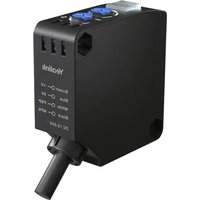
YPS20 - Door/window sensor Yealink - Free user manual and instructions
Find the device manual for free YPS20 Yealink in PDF.


| Product Type | Door/Window Sensor |
| Brand | Yealink |
| Model | YPS20 |
| Connectivity | Wireless (Zigbee 3.0) |
| Power Source | 1x CR123A (3V) battery |
| Battery Life | Up to 2 years (typical usage) |
| Detection Method | Magnetic contact (reed switch) |
| Operating Temperature | -10°C to 50°C |
| Dimensions | 70 × 35 × 20 mm (sensor); 70 × 14 × 14 mm (magnet) |
| Weight | 30 g (sensor only) |
| Mounting Type | Adhesive tape or included screws |
| Compatibility | Yealink Smart Hub or compatible Zigbee gateway |
| Security Features | Anti-tamper switch |
| Color | White |
| Certifications | CE, FCC |
| Cable Length | Not applicable (wireless) |
| Indoor/Outdoor Use | Indoor use only |
| Cleaning | Wipe with a dry, soft cloth. Do not use solvents. |
| Battery Replacement | User-replaceable; open the sensor cover to access battery compartment. |
| Repairability | Not user-serviceable; contact Yealink support for issues. |
Frequently Asked Questions - YPS20 Yealink
User questions about YPS20 Yealink
0 question about this device. Answer the ones you know or ask your own.
Ask a new question about this device
Download the instructions for your Door/window sensor in PDF format for free! Find your manual YPS20 - Yealink and take your electronic device back in hand. On this page are published all the documents necessary for the use of your device. YPS20 by Yealink.
USER MANUAL YPS20 Yealink
The Yealink solution uses the YPS20 to monitor the status of physical partitions in divisible and combinable meeting rooms. It controls the merging and separating of two rooms by detecting the presence of partition panels and executing the corresponding actions.
Step 1: Determine Sensor Installation Location
To determine an appropriate location for deploying the YPS20 sensor in a meeting room, 1. consider the following conditions:
- The sensor should be installed in a location that is generally out of reach and free from interference by moving objects or people. Ceiling or side wall installations are recommended.
- Ensure the optical axis is as perpendicular as possible to the partition. If perfect alignment is not possible, keep the angle less than 30° .
- After deployment, the distance between the sensor and the partition must be less than 1.5 meters. Additionally, when the partition is open, there should be no structural beams or obstacles blocking the light path to maintain detection accuracy (refer to the following table).
- If objects behind the partition may cause misinterpretation of the open/closed status, consider reducing the sensor's sensitivity to minimize interference from these objects. Adjust the sensitivity knob so that:2.
- Ensure the deployment position of the YPS20 relative to the partition is less than the effective distance.
- The distance from interfering objects behind the partition should be greater than the interference distance.
YPS20 offers 6 sensitivity levels. Refer to the following table for the corresponding active and interference distances at each level.
| Level 1 Level 2 Level 3 | Level 4 Level 5 Level 6 | |||||
| Active Distance (m) 0 0.05 | 0.5 | 0.7 | 1.3 | 1.5 | ||
| Interface Distance (m) 0 | 0.2 | 0.8 | 1.0 | 8 4 | ||

±10% variation may exist between individual units.
Step 2: Connect YPS20 to AP08
For actual deployment, the YPS20 will be used to connect the Yealink AP08 DSP to transmit the merge split signal.
Connect the YPS20 to the Phoenix male terminal.1.
Plug it into the AP08 GPIO Phoenix female terminal.2.
Power on the AP08 once the connection is secure.3.
YPS20 Wire Definitions:
• Brown: Power supply positive
- Blue: Ground
- White: Signal output (connect to AP08 GPIO input)
- Black: Not used
| YPS20 AP08 GPIO | In AP08 GPIO in Connector | |
| Brown | +12VDC | 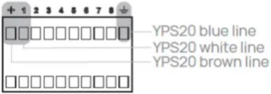 |
| White Input 1 | ||
| Black No Connection | ||
| Blue | GND | |
Step 3: Verify Sensor Status
After wiring is completed:
Open and close the partition and observe the YPS20 indicator lights to ensure proper 1. detection.
- Make sure the Action switch is set to the D position.

Troubleshooting Based on Indicator Lights:
| LED Status Possible Cause Solution | ||
| Green LED is off or blinking Sensor | or is too far from the partition or at the detection limit | Move the sensor closer to the partition |
| Green LED is steady, orange LED blinks or turns on when rooms are merged | Interference is affecting detection | Increase distance from interfering object or reduce sensitivity |
| Green LED is steady, orange LED turns off when rooms are divided | Sensor cannot detect the partition (e.g., dark-colored surface) | Move the sensor closer to the partition |
Step 4: Wiring and Installation Considerations
- If the cable length from YPS20 to AP08 is less than 10 meters, the default cable is sufficient.
- For distances over 10 meters, use AWG26 cable to extend the wiring (maximum extension: 20 meters).
Step 5: Special Case Handling
- Under normal circumstances, the infrared beam of the sensor should be perpendicular to the partition. If perpendicular detection is not possible, an angle deviation within 30° is allowed, and the distance from the YPS20 to the partition should be less than 1.5 meters.
- The sensor detects the open/closed status of the partition by emitting infrared light that reflects off it. An inclined installation reduces the effective detection range, which can be compensated by slightly reducing the distance between the sensor and the partition.
- Avoid direct sunlight or strong light interference to ensure accurate sensor detection
Step 6: Room Designer Configuration
- On the Room Designer homepage, click New to create a room. Enter the room information and click Confirm to proceed to the Room Setup Wizard.
- Select to create a Divisible Room. Fill in the room information and choose the appropriate conference room equipment.

Under Link View, double-click on AP08 to enter the Audio Flow.3.
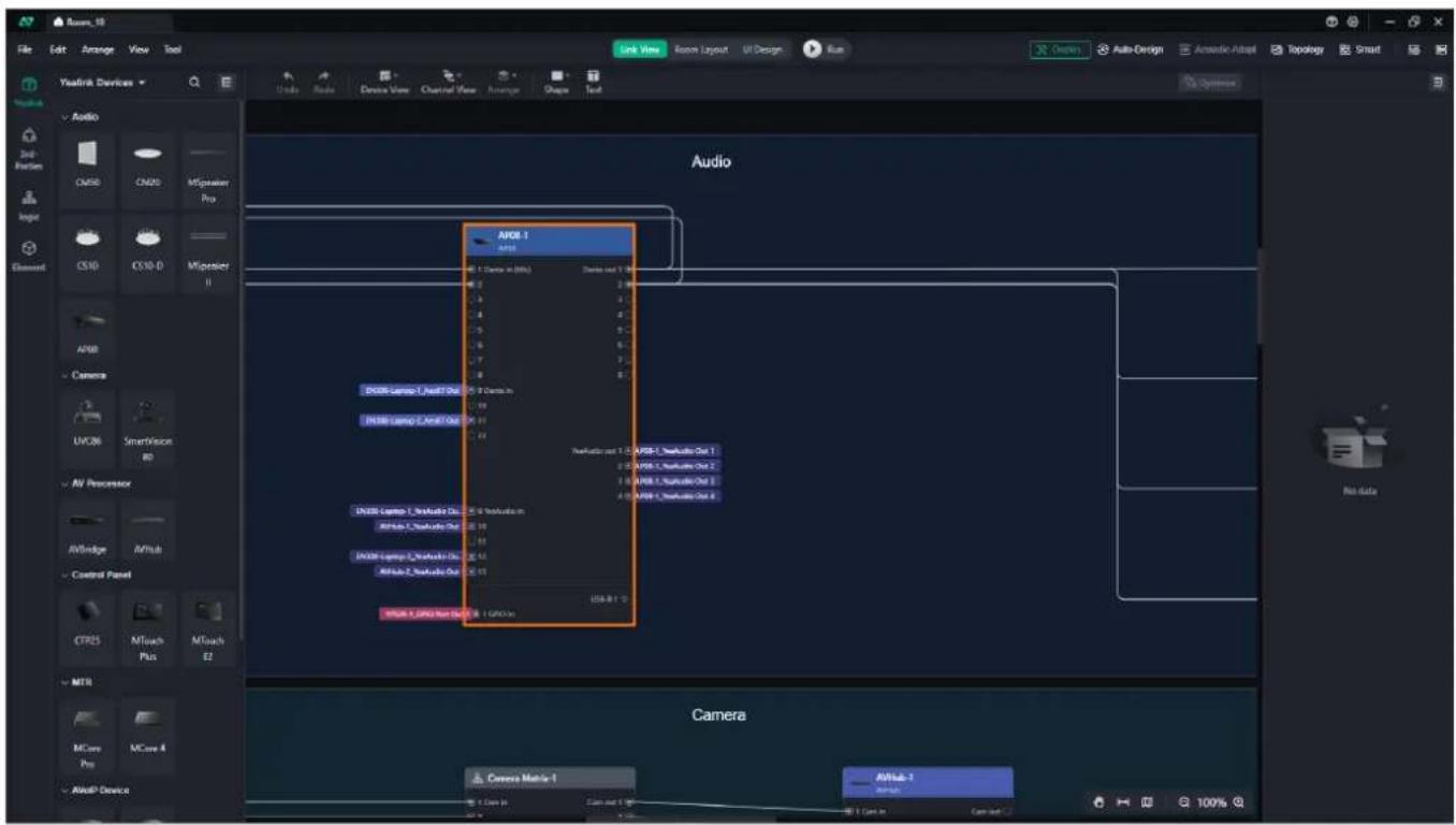
- Click Preset in the top right corner to switch between presets for divisible conference rooms or to combine room presets.
![graph TD A["1"] --> B["10"] C["2"] --> D["11"] E["3"] --> F["12"] G["4"] --> H["13"] I["5"] --> J["14"] K["6"] --> L["15"] M["7"] --> N["16"] O["8"] --> P["17"] Q["9"] --> R["18"] S["10"] --> T["19"] U["11"] --> V["20"] W["12"] --> X["21"] Y["13"] --> Z["22"] AA["14"] --> AB["23"] AC["15"] --> AD["2…](/content/2026/07/1458192/images/29c4e11f60e69ddb5e27a214fefe9a0502b3f50cbfd1a7b7545200416d817d69.jpg)
Brand : Yealink
Model : YPS20
Category : Door/window sensor