
CF25 - Refrigerator DOMETIC - Free user manual and instructions
Find the device manual for free CF25 DOMETIC in PDF.


| Product type | Compressor portable refrigerator |
| Brand | Dometic |
| Model | CF25 |
| Capacity | 25 liters |
| Dimensions (W x H x D) | 470 x 350 x 290 mm |
| Weight | 11 kg |
| Power supply | 12 V / 24 V DC and 230 V AC (via adapter) |
| Power consumption | 45 W in operation |
| Temperature range | -15 °C to +10 °C |
| Cooling function | Compressor with electronic control |
| Insulation | High performance, polyurethane foam |
| Features | Digital control, LED display, battery protection |
| Exterior material | Impact-resistant ABS plastic |
| Maintenance and cleaning | Clean with a soft cloth and soapy water. Manual defrosting required. |
| Safety | Protection fuse, reverse polarity protection |
| Spare parts and repairability | Available from Dometic after-sales service (filter, fan, thermostat) |
| Included accessories | 12 V cable, mains adapter, carrying handle |
| Applications | Camping, caravan, boat, mobile use |
| Warranty | 2 years (according to seller's conditions) |
Frequently Asked Questions - CF25 DOMETIC
User questions about CF25 DOMETIC
0 question about this device. Answer the ones you know or ask your own.
Ask a new question about this device
Download the instructions for your Refrigerator in PDF format for free! Find your manual CF25 - DOMETIC and take your electronic device back in hand. On this page are published all the documents necessary for the use of your device. CF25 by DOMETIC.
USER MANUAL CF25 DOMETIC
CF18, CF25, CF35, CF40, CF50
EN Compressor Cooler
Operating manual....6


Please read this operating manual carefully before starting the device. Keep it in a safe place for future reference. If the device is passed on to another person, this operating manual must be handed over to the user along with it.
The manufacturer cannot be held liable for damage resulting from improper usage or incorrect operation.
Contents
1 Explanation of symbols 7 2 Safety instructions 8 2.1 General safety....8 2.2 Operating the cooling device safely 9 3 Scope of delivery....10 4 Accessories....10 5 Intended use....11 6 Function description....11 6.1 Scope of functions....12 6.2 Operating and display elements .....13 7 Operation....15 7.1 Before initial use .....15 7.2 Energy saving tips....16 7.3 Connecting the cooler .....16 7.4 Using the battery monitor....18 7.5 Using the cooler 20 7.6 Setting the temperature 21 7.7 Switching off the cooler 22 7.8 Defrosting the cooler 22 7.9 Replacing the AC fuse (CF 35, CF 40, CF 50)....22 7.10 Replacing the DC plug fuse 23 7.11 Replacing the light bulb (CF 25, CF 35, CF 40, CF 50)....23 8 Cleaning and maintenance 24 9 Guarantee....24
10 Troubleshooting 25 11 Disposal 26 12 Technical data 27
1 Explanation of symbols

DANGER!
Safety instruction: Failure to observe this instruction will cause fatal or serious injury.

WARNING!
Safety instruction: Failure to observe this instruction can cause fatal or serious injury.

CAUTION!
Safety instruction: Failure to observe this instruction can lead to injury.

Failure to observe this instruction can cause material damage and impair the function of the product.

NOTE
Supplementary information for operating the product.
2 Safety instructions
2.1 General safety

WARNING!
- Do not operate the cooling device if it is visibly damaged.
- If this cooling device's power cable is damaged, it must be replaced by the manufacturer, customer service or a similarly qualified person in order to prevent safety hazards.
- This cooling device may only be repaired by qualified personnel. Improper repairs can lead to considerable hazards.
- This cooling device can be used by children aged 8 years or over, as well as by persons with diminished physical, sensory or mental capacities or a lack of experience and/or knowledge, providing they are supervised or have been taught how to use the cooling device safely and are aware of the resulting risks.
- Cleaning and user maintenance must not be carried out by children without supervision. Children must not play with the cooling device.
- Children must be supervised to ensure that they do not play with the cooling device.
- Always keep and use the cooling device out of the reach of children under the age of 8 years.
- Do not store any explosive substances such as spray cans with a flammable propellant in the cooling device.

CAUTION!
- Disconnect the cooling device from the power supply before each cleaning and maintenance.
- After every use.
Food may only be stored in its original packaging or in suitable containers.

NOTICE!
Check that the voltage specification on the type plate corresponds to that of the energy supply.
Only connect the cooling device as follows: - With the DC cable to a DC outlet in the vehicle - Or with the AC connection cable to the AC power supply.
- Never pull the plug out of the socket by the cable.
- If the cooling device is connected to the DC outlet: Disconnect the cooling device and other power consuming devices from the battery before connecting a quick charging device.
- If the cooling device is connected to the DC outlet: Disconnect the cooling device or switch it off when you turn off the engine. Otherwise you may discharge the battery.
- The cooling device is not suitable for transporting caustic materials or materials containing solvents.
- The insulation of the cooling device contains flammable cyclopentane and requires special disposal procedures. Deliver the cooling device at the end of its life-cycle to an appropriate recycling.
2.2 Operating the cooling device safely

CAUTION!
Before starting the cooling device, ensure that the power supply line and the plug are dry.

NOTICE!
- Do not use electrical devices inside the cooling device unless they are recommended by the manufacturer for the purpose.
- Do not place the cooling device near open flames or other heat sources (heaters, direct sunlight, gas ovens etc.). • Danger of overheating!
Ensure at all times that there is a minimum of 50 mm (2") ventilation on all four sides of the cooling device. Keep the ventilation area free of any objects that could restrict the air flow to the cooling components. Do not place the cooling device in closed compartments or areas with none or minimal air flow.
- Ensure that the ventilation openings are not covered.
- Do not fill the inner container with ice or liquids.
- Never immerse the cooling device in water.
- Protect the cooling device and the cable against heat and moisture.
3 Scope of delivery
No. in fig. 1, page 3 Quantity Description
| 11 Cooler | |||
| 21 Connection cable for DC connection | |||
| Only CF 35, CF 40, CF 50 | |||
| 3 | 1 | Connection cable for AC connection | |
| Only CF 35, CF 40, CF 50 | |||
| 4 | 2 | Carrying handle, consisting of: | |
| - 2 holders | |||
| - 1 handle | |||
| - 4 fastening screws | |||
| - | 1 | O | p e |
4 Accessories
Available as accessories (not included in the scope of delivery):
Description Ref. no.
| Insulated cover bag for CF 18 9600003792 | |
| Insulated cover bag for CF 25 | 9600003793 |
| Insulated cover bag for CF 35 | 9600003794 |
| Insulated cover bag for CF 40 | 9600003795 |
| Insulated cover bag for CF 50 | 9600003796 |
If you have questions regarding the accessories, contact your local service partner.
5 Intended use
The cooler is suitable for cooling and freezing foods.
The cooler is designed to be operated from:
- a DC on-board power supply of a vehicle, boat or caravan
- a DC auxiliary battery
- an AC power supply (CF 35, CF 40, CF 50)
For operating CF 18, CF 25 at 120 V~ you need an AC/DC power supply rectifier (accessory).

CAUTION! Health hazard!
Please check if the cooling capacity of the device is suitable for storing the food or medicine you wish to cool.
6 Function description
The cooler can refrigerate or freeze food products. A fast-acting and efficient cooling system provides maintenance-free cooling performance with a compressor and control module.
The cooler is designed for mobile use and can be carried by using a folding carrying bracket (CF 18), two recessed grips (CF 25) or two removable carrying handles (CF 35, CF 40, CF 50).
The cooler can withstand a short-term inclination of 30°, for example on boats.
6.1 Scope of functions
| CF18CF25 | CF35, CF40, CF50 | ||
| Power supply with priority circuit for connecting to the power supply – | - ● | ||
| Battery monitor to protect the vehicle battery 2-level 3-levelTurbo mode for rapid cooling –Display with temperature gauge (switches off automatically at low battery voltage)Temperature setting rotary-knob two buttons in steps of 1 °C (2 °F) | ●● | ●● | |
| Removable carrying handles – | - ● |
6.2 Operating and display elements
CF25, CF35, CF40
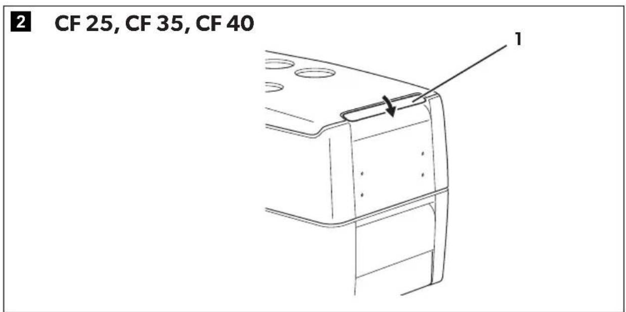
Lock for lid (fig. 2 1, page 3)
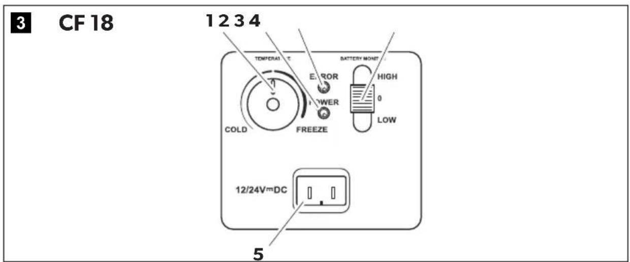
CF18
Operating panel and DC power supply inlet (fig. 3, page 3)
Item Description Explanation
| 1 TEMPERATURE Temperature controller, cooling temperature at the end positions: COLD: +10 °C (+50 °F) FREEZE: -18 °C (0 °F) | ||
| 2 POWER Status indication | ||
| LED lights up green: Device is switched on and ready for operation | ||
| LED lights up yellow: Set temperature has been reached | ||
| 3 ERROR LED flashes red: | Device is switched on but not ready for operation | |
| 4 BATTERY MONITOR | Switch-on device/battery monitor: | |
| 0: | Device is switched off | |
| HIGH: | Device is switched on, battery monitor is in HIGH mode | |
| LOW: | Device is switched on, battery monitor is in LOW mode | |
| 5 12/24 V--- | DC voltage supply inlet | |
CF25, CF35, CF40, CF50
Operating panel (fig. 4, page 4)
| Item Description Explanation | |
| 1 O NOFF | Switches the cooler on or off when the button is pressed for between one and two seconds |
| 2 POWER Status indication | |
| LED lights up green: Compressor is on | |
| LED lights up orange: Compressor is off | |
| LED flashes orange: Display switched off automatically due to low battery voltage | |
| 3 ERROR LED flashes red: Device is switched on but not ready for operation | |
| 4 SET Selects the input mode- Temperature setting- Celsius or Fahrenheit display- Set battery monitor | |
| 5 - | Display, shows the information |
| 6 UP + | Press once to increase the value |
| 7 DOWN - | Press once to decrease the value |
CF25
Connection sockets (fig. 5, page 4)
| Item Description | |
| 1 | DC voltage supply inlet |
CF35, CF40, CF50
Connection sockets (fig. 6, page 4)
| Item Description | |
| 1 | AC voltage supply inlet |
| 2 | Fuse holder |
| 3 | DC voltage supply inlet |
7 Operation
7.1 Before initial use

NOTE
Before starting your new cooler for the first time, you should clean it inside and outside with a damp cloth for hygienic reasons (please also refer to the chapter “Cleaning and maintenance” on page 24).
Mounting the handles (CF 35, CF 40, CF 50)
The handles are enclosed unassembled. If you wish to attach the handles, proceed as follows:
▶ Make a handle by putting two holders (fig. 7 1, page 4) and a handle (fig. 7 2, page 4) together. ▶ Fasten the grip with the enclosed screws in the holes provided.
Turning the lid stop around (CF 50)
You can turn the lid stop around if you want to open the lid from the other side. To do this, proceed as follows:
▶ Open the lid and pull it out (fig. 8 A, page 5). ▶ Turn the lid. ▶ Insert the lid in the lid holders on the side opposite the cooler (fig. 8 B, page 5).
Selecting the temperature units (CF 25, CF 35, CF 40, CF 50)
You can switch the temperature display between Celsius and Fahrenheit. This is how to do it:
▶ Switch on the cooler. ▶ Press the "SET" button (fig. 4 4, page 4) twice. ▶ Use the "UP+" (fig. 4 6, page 4) and "DOWN−" (fig. 4 7, page 4) buttons to select Celsius or Fahrenheit. √ The selected temperature units then appear in the display for a few seconds. The display flashes several times before it returns to the current temperature.
7.2 Energy saving tips
- Choose a well ventilated location which is protected from direct sunlight.
- Allow warm food to cool down first before placing it in the cooling device to keep cool.
- Do not open the cooling device more often than necessary.
- Do not leave the cooling device open for longer than necessary.
- Defrost the cooling device once a layer of ice forms.
- Avoid unnecessary low temperatures.
7.3 Connecting the cooler
AC extension cord

WARNING!
Because of potential safety hazards under certain conditions, the manufacturer strongly recommends against the use of an extension cord. However, if you must use an extension cord, it is absolutely necessary that it be a UL-Listed (in the United States) or a CSA-Listed (in Canada) appliance extension cord, with 10 A (minimum), 120 V electrical ratings.

CAUTION!
- Under no circumstances should you attempt to splice extension cord wires.
- Do not use power strips or 2-way splitters.
- Always unroll or uncoil an extension cord to avoid heat retention and possible melting.
▶ Select a UL/CSA listed 120 V~ / ≥ 10 A outdoor use extension cord according to the following table:
| 120 V~ | Maximum cord length | |||
| 10 ft. (3 m) | 25 ft. (7.6 m) | 50 ft. (15.2 m) | 100 ft. (30.5 m) | |
| Wire conductors | 3 | 3 | 3 | 3 |
| AWG | 14 (1.6 mm2) | 12 (2 mm2) | 12 (2 mm2) | 12 (2 mm2) |
DC extension cord

CAUTION!
- The manufacturer does not recommend using any type of DC extension cord.
- Under no circumstances should you attempt to splice extension cord wires.
- Do not use power strips or 2-way splitters.
- Always unroll or uncoil an extension cord to avoid heat retention and possible melting.
Select a 12 V/24 V---/≥ 10 A automotive use extension cord according to the following table:
| Maximum cord length | |
| 12 V--- | 3 ft. (0.9 m) 6 ft. (1.8 m) 10 ft. (3 m) 12 ft. (3.7 m) |
| 24 V--- | 6 ft. (1.8 m) 10 ft. (3 m) 15 ft. (4.6 m) 25 ft. (7.6 m) |
| AWG | 14 (1.6 mm 2 ) 12 (2 mm 2 ) 10 (2.6 mm 2 ) 8 (3.3 mm 2 ) |
Connecting to a battery (vehicle or boat)
The cooler can be operated with 12 V--- or 24 V---.

NOTICE! Danger of damage!
Disconnect the cooler and other consumer units from the battery before you connect the battery to a quick charging device.
Overvoltage can damage the electronics of the device.
For safety reasons the cooler is equipped with an electronic system to prevent polarity reversal. This protects the cooler against short-circuiting when connecting to a battery.
Using the fused DC plug

NOTICE! Danger of damage!
For protection of the device the DC cable supplied includes a fuse inside the plug. Do not remove the fused DC plug. Only use the DC cable supplied.
Plug the DC connection cable (fig. 1 2, page 3) into the DC power supply inlet of the cooler (fig. 5 1, page 4/fig. 6 3, page 4). Connect the connection cable to the DC power outlet.
Connecting to an AC power supply (e.g. in the home or office) (CF35, CF40, CF50)

DANGER! Danger of electrocution!
- Never handle plugs and switches with wet hands or if you are standing on a wet surface.
- If you are operating your cooler on board a boat from a power supply connection of 120 V~, you must install a residual current circuit breaker between the 120 V AC power supply and the cooler. Seek advice from a trained technician.
The coolers have an integrated multi-voltage power supply with a priority circuit for connecting to an AC voltage source. The priority circuit automatically switches the cooler to power supply operation if the device is connected to an AC power supply, even if the DC connection cable is still attached.
When switching between the AC power supply and the battery supply, the red LED may light up briefly.
Plug the AC connection cable (fig. 1 3, page 3) into the AC power supply inlet of the cooler (fig. 6 1, page 4). Connect the connection cable to the AC power outlet.
7.4 Using the battery monitor
The device is equipped with a multi-level battery monitor that protects your vehicle battery against excessive discharging when the device is connected to the on-board DC supply.
If the cooler is operated when the vehicle ignition is switched off, the cooler switches off automatically as soon as the supply voltage falls below a set level. The cooler will switch back on once the battery has been recharged to the restart voltage level.

NOTICE! Danger of damage!
When switched off by the battery monitor, the battery will no longer be fully charged. Avoid continuous starting and shutting off of the vehicle's engine when using the cooler in an automotive environment. Allow the vehicle to recharge the battery before powering the cooler on.
In "HIGH" mode, the battery monitor responds faster than at the levels "LOW" and "MED" (see the following table).
| Battery monitor mode | CF18CF25, CF35, CF40, CF50 | ||||
| LOW | HIGH | LOW | MED | HIGH | |
| Switch-off voltage at 12 V | 10.4 V | 11.5 V | 11.4 V | 11.8 V | |
| Restart voltage at 12 V | 11.5 V | 12.5 V | 12.2 V | 12.6 V | |
| Switch-off voltage at 24 V | 22.1 V | 24.0 V | 21.5 V | 24.1 V | 24.6 V |
| Restart voltage at 24 V | 23.6 V | 25.4 V | 23.0 V | 25.3 V | 26.2 V |
Selecting the battery monitor mode (CF 25, CF 35, CF 40, CF 50)
Switch on the cooler. Press the "SET" button (fig. 4 4, page 4) three times. Use the "UP+" (fig. 4 6, page 4) and "DOWN-" (fig. 4 7, page 4) buttons to select the battery monitor mode. The selected mode then appears in the display for a few seconds. The display flashes several times before it returns to the current temperature.

NOTE
When the cooler is supplied by the starter battery, select the battery monitor mode "HIGH". If the cooler is connected to a supply battery, the battery monitor mode "LOW" will suffice.
If you wish to operate the cooler from the AC power supply, set the battery monitor to the "LOW" position.
7.5 Using the cooler

NOTICE! Danger of overheating!
Ensure at all times that there is sufficient ventilation so that the heat generated during operation can dissipate. Ensure that the ventilation slots are not covered. The cooler MUST maintain a MINIMUM of 2 inches (51 mm) away from walls or similar surfaces which could restrict important air flow requirements of the cooling system.
Place the cooler on a firm foundation.
Make sure that the ventilation slots are not covered and that the heated air can dissipate.

NOTE
Place the cooler as shown (fig. 1, page 3). If you operate the box in a different position it can be damaged.
Close the cooler, see chapter "Connecting the cooler" on page 16.

NOTE
If you wish to operate the cooler from the AC power supply, set the battery monitor to the "LOW" position.

NOTICE! Danger from excessively low temperature!
Ensure that only those objects are placed in the cooler that are intended to be cooled at the selected temperature.
CF18
Set the slide switch (fig. 3 4, page 3) to "HIGH" when providing power from your vehicle's DC power source.
Set the slide switch (fig. 3 4, page 3) to "LOW" when providing power from an external DC power supply source.
The "POWER" LED is lit green.
The cooler starts cooling the interior.
When the cooling temperature has been reached, the "POWER" LED is lit yellow.
CF25, CF35, CF40, CF50
Press the "ON/OFF" button (fig. 4 1, page 4) for one to two seconds. The "POWER" LED lights up. The display (fig. 4 5, page 4) switches on and shows the current cooling temperature.

NOTE
The temperature displayed is that of the middle of the interior. The temperatures elsewhere can deviate from this temperature.
The cooler starts cooling the interior.

NOTE
When operating with the battery, the display switches off automatically if the battery voltage is low. The LED "POWER" flashes orange.
Locking the cooler (CF 35, CF 40)
Close the lid. Press the lock (fig. 2 1, page 3) down until it latches in place audibly.
7.6 Setting the temperature
CF18
Set the cooling temperature with the temperature controller (fig. 3 1, page 3).
CF25, CF35, CF40, CF50
Press the "SET" button (fig. 4 4, page 4) once. Use the "UP+" (fig. 4 6, page 4) and "DOWN-" (fig. 4 7, page 4) buttons to select the cooling temperature. The cooling temperature appears in the display for a few seconds. The display flashes several times and then the current temperature is displayed again.
7.7 Switching off the cooler
Empty the cooler. Switch the cooler off. Pull out the connection cable.
If you do not want to use the cooler for a longer period of time:
Leave the cover slightly open. This prevents odor build-up.
7.8 Defrosting the cooler
Humidity can form frost in the interior of the cooling device or on the vaporizer. This reduces the cooling capacity. Defrost the device in good time to avoid this.

NOTICE! Danger of damage!
Never use hard or pointed tools to remove ice or to loosen objects which have frozen in place.
To defrost the cooler, proceed as follows:
Take out the contents of the cooler. If necessary, place them in another cooling device to keep them cool. Switch off the device. Leave the cover open. Wipe off the defrosted water.
7.9 Replacing the AC fuse (CF 35, CF 40, CF 50)

DANGER! Danger of electrocution!
Disconnect the connection cable before you replace the device fuse.
Pull off the connection cable. Pry out the fuse insert (fig. 6 2, page 4) with a screwdriver. Replace the defective fuse with a new one that has the same rating (T4AL 250 V). Press the fuse insert back into the housing.
7.10 Replacing the DC plug fuse
Pull the adapter sleeve (fig. 9 4, page 5) off of the plug. Unscrew the screw (fig. 9 5, page 5) out of the upper half of the housing (fig. 9 1, page 5). Carefully raise the upper half of the housing from the lower (fig. 9 6, page 5) half. Take out the contact pin (fig. 9 3, page 5). Replace the defective fuse (fig. 9 2, page 5) with a new fuse of the same type and rating (3AG, Fast Acting, 10 A). Re-assemble the plug in the reverse order.
7.11 Replacing the light bulb (CF 25, CF 35, CF 40, CF 50)
Press the switch pin (fig. 10 2, page 5) downwards so that the transparent part (fig. 10 1, page 5) of the lamp can be removed at the front.
Replace the light bulb.

NOTE
The LEDs in the light bulb must be aligned with the transparent part of the lamp.
Press the transparent part of the lamp back into the housing.
8 Cleaning and maintenance

WARNING!
Always disconnect the device from the power supply before you clean and service it.

NOTICE! Risk of damage
- Never clean the cooler under running water or in dish water.
- Do not use abrasive cleaning agents or hard objects during cleaning as these can damage the cooler.
Occasionally clean the device interior and exterior with a damp cloth. Make sure that the air inlet and outlet vents on the device are free of any dust and dirt, so that heat can be released and the device is not damaged.
9 Guarantee
The statutory warranty period applies. If the product is defective, please contact the manufacturer's branch in your country (see the back of the instruction manual for the addresses) or your retailer.
For repair and guarantee processing, please include the following documents when you send in the device:
• A copy of the receipt with purchasing date - A reason for the claim or description of the fault
10 Troubleshooting
Fault Possible cause Suggested remedy
| Device does not function, LED does not glow. | No voltage was detected in the DC power outlet. | In most vehicles the ignition must be turned on before power will be supplied to the DC power outlet. |
| No voltage present in the AC voltage outlet. | Try using another plug outlet. | |
| The device fuse is defective. | Replace the device fuse, see chapter “Replacing the AC fuse (CF 35, CF 40, CF 50)” on page 22. | |
| The integrated power supply adapter is defective. | This can only be repaired by an authorized repair center. | |
| The device does not cool (plug is inserted, “POWER” LED is lit). | Defective compressor. | This can only be repaired by an authorized repair center. |
| The device does not cool (plug is inserted, “POWER” LED flashes orange, display is switched off). | Battery monitor is set too high. | Select a lower battery monitor setting. |
| Battery voltage is too low. | Test the battery and charge it as needed. | |
| When operating from the DC outlet: The ignition is on and the device is not working and the LED is not lit. | The DC outlet is dirty. This results in a poor electrical contact. | If the plug of your cooler becomes very warm in the DC outlet, either the DC outlet must be cleaned or the plug has not been assembled correctly. |
| The fuse of the DC plug has blown. | Replace the fuse in the DC plug, see chapter “Replacing the DC plug fuse” on page 23. | |
| The vehicle fuse has blown. | Replace the vehicle’s DC outlet fuse. Please refer to your vehicle’s operating manual. |
Fault Possible cause Suggested remedy
| The display shows an error message (e.g. “Err1”) and the appliance does not cool. | The appliance has switched off due to an internal fault. | This can only be repaired by an authorized repair center. |
| The interior light of a compartment flashes. | The lid of the compartment has been left open for more than three minutes. | Close the lid of the compartment. |
11 Disposal
▶ Place the packaging material in the appropriate recycling waste bins wherever possible.

If you wish to finally dispose of the product, ask your local recycling centre or specialist dealer for details about how to do this in accordance with the applicable disposal regulations.
12 Technical data
| CF18CF25 | ||
| Connection voltage: 12/24 V--- | ||
| Rated current- 12 V---: 7.0 A 7.0 A- 24 V---: 3.0 A 3.0 A- 120 V~ : | - | |
| Cooling capacity: +10 °C to -18 °C (+50 °F to +0.4 °F) | ||
| Usable capacity: 18 l (0.64 cu. ft.) | 23 l (0.82 cu. ft.) | |
| Climate class: | N, ST, T | |
| Ambient temperature: | 18 °C to 43 °C (+50 °F to 109.4 °F) | |
| Noise emission: | - | |
| Refrigerant quantity: | 38 g (1.34 oz.) | 40 g (1.41 oz.) |
| CO2 equivalent: | 0.054 t (119.05 lb.) | 0.057 t (125.66 lb.) |
| Global warming potential (GWP): 1430 | ||
| Dimensions (W x H x D) in mm (in.): | 300 x 414 x 465(11.81 x 16.30 x 18.31) | 260 x 425 x 550(10.24 x 16.73 x 21.65) |
| Weight: | 12 kg (26.46 lb.) | 12.7 kg (28 lb.) |
| Test/certificates: |  Intertek4009683 Intertek4009683 | |
| CF35CF40 | ||
| Connection voltage: 12/24 V--- and 120 V~ | ||
| Rated current-12 V---:-24 V---:-120 V~: | 731 (1.1 cu. ft.) 36 l (1.3 cu. ft.) | |
| Cooling capacity: +10 °C to -18 °C (+50 °F to +0.4 °F) | ||
| Usable capacity: 31 l (1.1 cu. ft.) 36 l (1.3 cu. ft.) | ||
| Climate class: N, ST, T | ||
| Ambient temperature: 18 °C to 43 °C (+50 °F to 109.4 °F) | ||
| Noise emission: | 45 dB(A) | |
| Refrigerant quantity: | 42 g (1.48 oz.) | |
| CO2 equivalent: | 0.060 t (132.28 lb.) | |
| Global warming potential (GWP): 1430 | ||
| Dimensions (W x H x D) in mm (in.): 360 x | 385 x 580(14.17 x 15.16 x 22.83) | 360 x 445 x 580(14.17 x 17.52 x 22.83) |
| Weight: | 15.5 kg (34.61 lb.) | 17.2 kg (37.92 lb.) |
| Test/certificates: |  US File No: SA 12891CF50 US File No: SA 12891CF50 | |
| Connection voltage: 12/24 V--- and 120 V~ | ||
| Rated current | ||
| -12 V---: | 7 | |
| -24 V---: | 3 | |
| -120 V~ : | 1 | |
| Cooling capacity: +10 °C to -18 °C (+50 °F to +0.4 °F) | ||
| Usable capacity: 47 l (1.7 cu. ft.) | ||
| Climate class: N, ST, T | ||
| Ambient temperature: 18 °C to 43 °C (+64.4 °F to 109.4 °F) | ||
| Noise emission: 45 dB(A) | ||
| Refrigerant quantity: 45 g (1.59 oz.) | ||
| CO2 equivalent: | 0.064 t (141.1 lb.) | |
| Global warming potential (GWP): 1430 | ||
| Dimensions (W x H x D) in mm (in.): | 360 x 480 x 630(14.17 x 18.9 x 24.8) | |
| Weight: | 18 kg (39.68 lb.) | |
| Test/certificates: |  |  |

NOTE
If the ambient temperature is above 32\ °C ( 90\ °F ), the minimum temperature cannot be attained.
The refrigerant circuit contains R134a.
Contains fluorinated greenhouse gases
Hermetically sealed equipment
CF25, CF35, CF40, CF50
CF25, CF35, CF40, CF50
CF25, CF35, CF40, CF50
Solo CF35, CF40, CF50
Solo CF35, CF40, CF50
CF25, CF35, CF40, CF50
CF25, CF35, CF40, CF50
CF25, CF35, CF40, CF50
Only CF35, CF40, CF50
CF25, CF35, CF40, CF50
CF25, CF35, CF40, CF50
CF25, CF35, CF40, CF50
dometic.com/sales-offices
- EN COMPRESSOR COOLER
- CONTENTS
- EXPLANATION OF SYMBOLS
- DANGER
- WARNING
- CAUTION
- NOTE
- SAFETY INSTRUCTIONS
- GENERAL SAFETY
- NOTICE
- OPERATING THE COOLING DEVICE SAFELY
- SCOPE OF DELIVERY
- ACCESSORIES
- INTENDED USE
- CAUTION! HEALTH HAZARD
- FUNCTION DESCRIPTION
- SCOPE OF FUNCTIONS
- OPERATING AND DISPLAY ELEMENTS
- CF25, CF35, CF40, CF
- CF
- CF35, CF40, CF
- OPERATION
- BEFORE INITIAL USE
- MOUNTING THE HANDLES (CF 35, CF 40, CF 50)
- TURNING THE LID STOP AROUND (CF 50)
- SELECTING THE TEMPERATURE UNITS (CF 25, CF 35, CF 40, CF 50)
- ENERGY SAVING TIPS
- CONNECTING THE COOLER
- AC EXTENSION CORD
- DC EXTENSION CORD
- CONNECTING TO A BATTERY (VEHICLE OR BOAT)
- NOTICE! DANGER OF DAMAGE
- USING THE FUSED DC PLUG
- CONNECTING TO AN AC POWER SUPPLY (E.G. IN THE HOME OR OFFICE) (CF35, CF40, CF50)
- DANGER! DANGER OF ELECTROCUTION
- USING THE BATTERY MONITOR
- SELECTING THE BATTERY MONITOR MODE (CF 25, CF 35, CF 40, CF 50)
- USING THE COOLER
- NOTICE! DANGER OF OVERHEATING
- NOTICE! DANGER FROM EXCESSIVELY LOW TEMPERATURE
- LOCKING THE COOLER (CF 35, CF 40)
- SETTING THE TEMPERATURE
- SWITCHING OFF THE COOLER
- DEFROSTING THE COOLER
- REPLACING THE AC FUSE (CF 35, CF 40, CF 50)
- REPLACING THE DC PLUG FUSE
- REPLACING THE LIGHT BULB (CF 25, CF 35, CF 40, CF 50)
- CLEANING AND MAINTENANCE
- NOTICE! RISK OF DAMAGE
- GUARANTEE
- TROUBLESHOOTING
- DISPOSAL
Brand : DOMETIC
Model : CF25
Category : Refrigerator