2010 - Manual lawn mower MTD - Free user manual and instructions
Find the device manual for free 2010 MTD in PDF.
User questions about 2010 MTD
0 question about this device. Answer the ones you know or ask your own.
Ask a new question about this device
Download the instructions for your Manual lawn mower in PDF format for free! Find your manual 2010 - MTD and take your electronic device back in hand. On this page are published all the documents necessary for the use of your device. 2010 by MTD.
USER MANUAL 2010 MTD
For problems or questions, DO NOT return this product to the store. Contact your Customer Service Agent at 1-800-521-8559.
Jenn Feng Industrial Co., Ltd.
No. 19, Lane 118, Min Tsu Road, sec. 2
Ping Chang City, Taoyuan, Taiwan, R.O.C.
Made in China/Made in China/Made in China
OWNER'S OPERATING MANUAL
Handy Push Reel Mower
MANUEL D'UTILSATION
Alimentation Autonome
MANUAL DEL USUARIO
Segador a Bobina
Model No. 2010, 2011
SAFETY RULES
Thanks for choosing our McCulloch garden tool, we are convince that you will be satisfied with this low cost, no noise and no lawn mower pollution's please read all instructions in this manual carefully before using mower.
Inspect your lawn for any debris or foreign objects and remove them before mowing.
- Never place your hands, fingers or feet inside the reel.
Although not powered by a motor, when the wheels turn, the reel cuts.
- Never mow when the grass is wet enough to be slippery.
- Don't place your hands or feet near a moving part of the mower.
- Don't operate the mower while barefoot or wearing sandals.
- Walk slowly, never run. Always be sure of your footing when operating the mower.
- Never intentionally strike or ram trees, fences, etc. This can cause injuries or severely damage the mower.
- Remember that this mower is a precision piece of lawn care equipment. Treat it as such by exercising caution when using it.
Make sure your mower is in safe operating condition. Don't attempt to operate the mower if it is damaged. have it repaired first.
OPERATION
- HANDLE
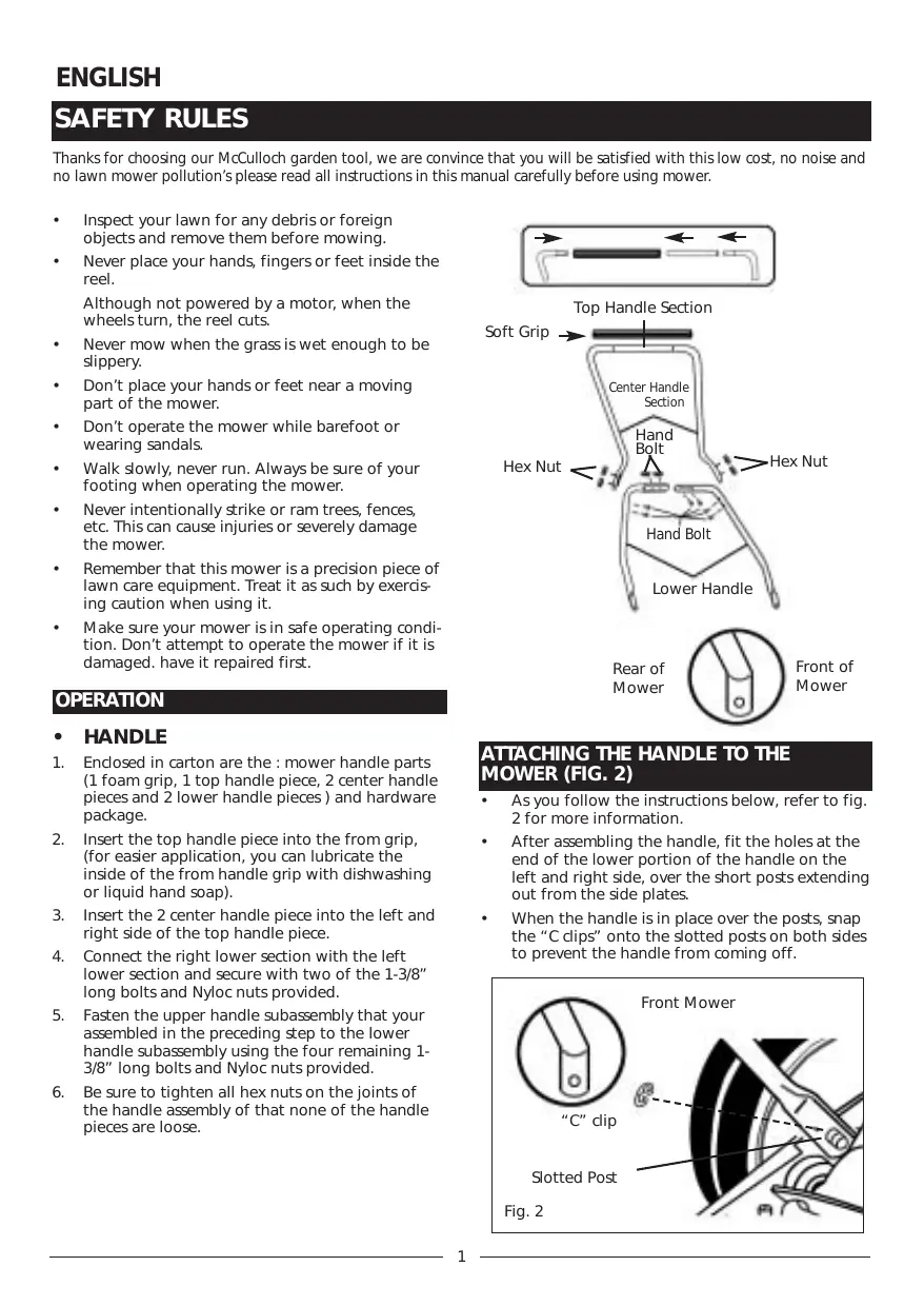
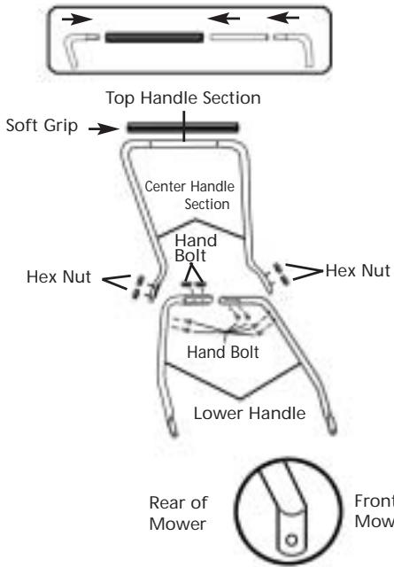
- Enclosed in carton are the : mower handle parts (1 foam grip, 1 top handle piece, 2 center handle pieces and 2 lower handle pieces) and hardware package.
- Insert the top handle piece into the from grip, (for easier application, you can lubricate the inside of the from handle grip with dishwashing or liquid hand soap).
- Insert the 2 center handle piece into the left and right side of the top handle piece.
- Connect the right lower section with the left lower section and secure with two of the 1-3/8" long bolts and Nyloc nuts provided.
- Fasten the upper handle subassembly that your assembled in the preceding step to the lower handle subassembly using the four remaining 1-3/8" long bolts and Nyloc nuts provided.
- Be sure to tighten all hex nuts on the joints of the handle assembly of that none of the handle pieces are loose.
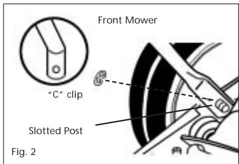
ATTACHING THE HANDLE TO THE MOWER (FIG. 2)
- As you follow the instructions below, refer to fig. 2 for more information.
After assembling the handle, fit the holes at the end of the lower portion of the handle on the left and right side, over the short posts extending out from the side plates. - When the handle is in place over the posts, snap the "C clips" onto the slotted posts on both sides to prevent the handle from coming off.
MINOR CUTTING HEIGHT ADJUSTMENTS (FIG. 3)
- These units can be adjusted to offer a cutting height range from 1/2 to 1-3/4 simply by adjusting the roller assembly.
- As you follow the instructions below, refer to fig. 3 for more information.
- To achieve the lowest cutting position, loosen and remove the nuts on both sides of the roller assembly. Position the bolt through the bottom hole of the plastic roller bracket and top hole of the mower side plate.
- To achieve the highest cutting position, loosen and remove the nuts on both sides of the roller assembly. Position the bolt through the top hole of the plastic roller bracket and bottom hole of the mower side plate.
- Other cutting heights can be obtained by positioning the bolts through other hole locations.

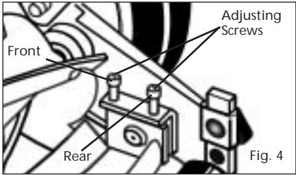
MOWER BLADE ADJUSTMENT (FIG. 4)
- The blades have been preadjusted before leaving the factory.
- Misalignment can occur resulting in blades that are too loose or too tight. If this happens, you will notice a rough, uneven cut or hard-pushing mower.
- All adjustments are made from the rear of the mower (opposite from the bar with the logo decal). Each end of the cutting bar can be adjusted separately.
- As you follow the instructions below, refer to Fig.4 for more information.
- The cutting bar blade (located under the reel) pivots. The front screws move the cutter bat away from the blades, while the rear screws move the cutter bar toward the blades.
- Adjusting the screws is a very sensitive procedure. 1-16th of a turn is considered a major adjustment.
- Before tightening one adjusting screw, be sure to loosen the opposing screw and equal amount.
LOOSENING THE BLADES
- The cutter bar blade must be moved further from the cutting reel.
- Loosen both back screws equally by turning them counter-clockwise.
- Tighten both front screws equally by turning them clockwise.
TIGHTENING THE BLADES
- The cutter bar must be moved closer to the cutting reel.
- Loosen both front screws equally by turning them counter-clockwise.
- Tighten both back screws equally by turning them clockwise.
CHECKING ADJUSTMENTS
- Turn mower upside down.
- Insert a piece of paper (i.e., writing or newspaper between the cutter bar and the reel blades, and carefully turn the reel blades by hand.
- All blades should slice the paper evenly the entire length of the cutter bar while the reel turns smoothly.
- If the mower has an intermittent cut, adjustment should be made to the appropriate side of the blades to attain proper cutting action.
GENERAL CARE
- Minimum care is required to assure smooth operation of your mower.
- To avoid damage to the mower or cutting blades, keep the area to be mowed free from any debris.
- We suggest a routine application of oil or lubricant (i.e., WD-40). This should be applied to all cutting surfaces, the cutting reel axle shaft and wheels.
SHARPENING THE CUTTING BLADES
- When the mower is properly lubricated and adjusted, sharpening should not be necessary for several years.
However, the following steps will allow you to do the procedure yourself at relatively little expense. - Spread a thin layer of lapping compound on the front edge of the reel blades.
- Adjust the cutter bar so that the cutter bar blade has light but firm contact with the reel blades across the full width of the cutter bar.

WARNING: Do not overtighten the adjusting screws, as this could damage the cutter bar. Both screws must be tight on the final adjustment.
- Turning the reel blades backward, until the reel blades rotate retativety free and the front edge of the cutter bar blade is polished.
- Remove wheels; reverse pinions and pawls so that the beveled edge of the pawl is on the right.
NOTE : It is recommended to use and industrial or valve lapping compound between 100-240 grit. This is usually available at an industrial or automotive supply store. If professional sharpening is required, consult your local yellow pages for lawn mower repair services.