
ELPMB47 - Projector EPSON - Free user manual and instructions
Find the device manual for free ELPMB47 EPSON in PDF.
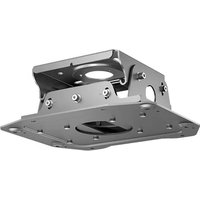


| Product type | Ceiling projector mount |
| Compatible brand | Epson |
| Compatible models | Epson projectors with compatible mount (ELPMB47) |
| Material | Steel and ABS plastic |
| Color | White |
| Dimensions (L x W x H) | 300 x 200 x 100 mm |
| Weight | 0.6 kg |
| Maximum load capacity | 15 kg |
| Horizontal rotation | 360° |
| Vertical tilt | ±15° |
| Ceiling distance | 50-200 mm adjustable |
| Ceiling fixing | Screws and anchors included (for concrete or wood ceiling) |
| Installation | Requires drilling and ceiling fixing |
| Maintenance | Clean with a soft, dry cloth |
| Security | Integrated security lock to prevent theft |
| Warranty | 2 years |
| Repairability | Spare parts available from the manufacturer |
Frequently Asked Questions - ELPMB47 EPSON
User questions about ELPMB47 EPSON
0 question about this device. Answer the ones you know or ask your own.
Ask a new question about this device
Download the instructions for your Projector in PDF format for free! Find your manual ELPMB47 - EPSON and take your electronic device back in hand. On this page are published all the documents necessary for the use of your device. ELPMB47 by EPSON.
USER MANUAL ELPMB47 EPSON


Instruction Manual (this document)


Operation


Operation

Vertical tilt angle

Horizontal tilt angle

Left/right rotation angle

Front/back slide
Contents
Included Items List 20
Safety Instructions 21
Precautions on Where to Mount the Projector 23
Installation 24
Removing the Ceiling Plate from the Projector Plate 24
Installing the Ceiling Plate to the Ceiling 25
Mounting to a Concrete Ceiling 26
Fitting the Projector Plate to the Projector 27
Fitting the Projector Plate to the Ceiling Plate 28
Adjusting the Installation Position 29
Moving the Projected Images Higher or Lower 29
Tilting the Projected Images to the Right or Left 30
Adjusting the Size of the Projected Images 30
Installing the Safety Wires 31
Inquiries 33
Specifications 33
Included Items List
Check the following list to confirm that you have all of the supplied items. If by any chance there is anything missing or damaged, please contact your dealer.
□ Ceiling plate □ Projector plate

The ceiling plate and projector plate are preassembled. Separate them before starting the installation.
☐ Projector mounting screws: 4 pcs. (M6 x 16)
□ Hexagon wrench (M6) □ Hexagon wrench (M8)


Safety wires: 2 pcs. (1.5 m, φ 1.5 mm)
Wire clips: 2 pcs.
User's Guide (this guide)


Safety Instructions
Read this document carefully to assemble and install this product safely and correctly. Be sure to follow the safety precautions. Keep these instructions close at hand to help solve any points you do not understand.
So that you can use the product safely and correctly, symbols are applied in this guide and on the product to indicate possible harm to the user or to others and the risk of damage to property. The indications and their meaning are as follows. Make sure you understand them properly before reading this guide.
 | Warning | This symbol indicates information that, if ignored, could possibly result in death or personal injury due to incorrect handling. |
 | Caution | This symbol indicates information that, if ignored, could possibly result in personal injury or physical damage due to incorrect handling. |
Carefully read the warnings in "Safety Instructions / Support and Service Guide" supplied with your projector before starting the installation to determine a suitable place to install it.

Warning
- The installation work should be performed only by specialists with the required technical know-how and ability. Incomplete assembly or installation could cause the projector and ceiling mount to fall and cause injury.
- This product weighs approximately 11 kg. When transporting or moving the product, handle it with care to avoid injury.
- Do not install the ceiling mount on an inclined or weak surface.
The ceiling must be strong enough to install the projector and ceiling mount. Before starting the installation, carefully check the weight of the projector and the ceiling mount. Make sure the ceiling is strong enough and use the most appropriate methods to prevent the projector from falling.
Do not install the product in a location where it might be exposed to vibration or shock.
Otherwise the product or the installation surface could be damaged. If the product falls, it could result in death or personal injury.

Warning
● Always follow the instructions below when installing the ceiling mount. If installation work is not carried out correctly, the projector and ceiling mount could fall and cause injury.
- Check the structure and materials of the mounting location and use the most appropriate construction method.
- Do not hang or mount anything except the specified projector from or on the ceiling mount. The projectors that can be mounted on this ceiling mount are listed in the catalogs.
- Do not hang from the ceiling mount or apply excessive force to it during or after installation.
- Tighten the screws firmly. Also, never loosen or remove any screws carelessly when mounting or removing the ceiling mount.
- Never disassemble or remodel the ceiling mount unless indicated in this manual.
● Install the supplied safety wire to prevent the projector from falling.
The safety wire also prevents the projector from swaying during an earthquake or vibration.
p.31
- Applying a screw-locking adhesive, lubricant, oil or other substance to the points at which the projector is fixed to the ceiling mount can make the case crack and the projector fall, leading to damage or injury. Do not use any sort of adhesive, lubricant or oil when installing or adjusting the ceiling mount.
- Never loosen any bolts, screws, or nuts after installation. Also, check periodically that no screws have come loose. If you find a loose screw, tighten it firmly.
- Do not use the ceiling mount and refer all repairs to qualified service personnel under the following conditions:
• The ceiling mount fell off or was broken before installation. • The supplied parts have problems and do not work correctly.
● Unplug the projector before installing.
● Handle the power cord carefully.
Incorrect handling could cause fire or electric shock. Observe the following precautions when handling:
- Do not handle the cord with wet hands.
- Do not use a cord that is damaged or modified.
Do not install or use the projector in locations where it could be splashed with water, such as outdoors, in a bathroom, or in a shower room. Do not install in locations subject to high levels of humidity.
This could cause fire or electric shock.
When cleaning, do not use a wet cloth or alcohol, benzine, thinner, and so on.
If water enters the projector, the casing may degrade and break, which could cause an electric shock.
Do not strongly pull or pinch the projector's power cord during installation. Be careful especially when passing the power cord through the pole.
If the power cord is damaged, it could cause fire or an electric shock. Contact your dealer if the wires of the power cord become exposed or broken.

Caution
At least two people are needed for the installation. Make sure to provide a sturdy scaffold for this work.
Otherwise, you may fall or drop the projector and cause injury.
Precautions on Where to Mount the Projector
Carefully read the warnings in "Safety Instructions / Support and Service Guide" supplied with your projector before starting the installation to determine a suitable place to install it. In particular, pay attention to the following items.
- Set the projector up in a location where direct sunlight or strong light from fluorescent lamps does not shine onto the receiver for the remote control. Strong light shining onto the receiver for the remote control may interfere with remote control operations.
- Install the projector so it is away from the air outlet of air conditioners or other similar devices. If air from an air conditioner blows directly onto the projector, the surrounding temperature increases and the projector may not operate correctly. ● Make sure there is a big enough gap between the projector and the wall. See the User's Guide supplied with your projector for details on the necessary distance. If the projector is too close to the wall, the surrounding temperature increases and the projector may not operate correctly.
- To limit the effect of external noise, we recommend that you position the projector so that the cable connecting it to a computer or other devices is no longer than 20 meters. ● The projector should be installed in a location that is free from dust and moisture to prevent the lens and internal optical parts from becoming dirty.
- Do not install the projector in a location beyond its operating temperature range. Doing so can cause it to malfunction.
- Closing the curtains in a bright room makes the projected image easier to see.
Installation
Removing the Ceiling Plate from the Projector Plate
The ceiling plate is fitted to the projector plate at the factory. Use the following procedure to separate them.
Procedure

1 Remove the screws for the vertical tilt adjustment points on both sides using the supplied M8 hexagon wrench.

② Remove the ceiling plate from the projector plate.
Installing the Ceiling Plate to the Ceiling
Determine the distance to the screen and locate the mounting position before mounting the ceiling plate.
The distance varies according to the type of the lens unit installed on the projector. See the "User's Guide" supplied with the projector.
Procedure
Refer to the ceiling template below to cut the bolt-mounting holes into the ceiling.
Ceiling template (units: mm)

Note
When installing this product after uninstalling the ELPMB22, you can use the mounting holes that are already in the ceiling as they are.
After installing, you cannot rotate the projector beyond ±5° to the left or right. Check that the projector is facing in the correct direction before installing.
Mounting to a Concrete Ceiling
When installing the ceiling mount on a concrete ceiling, use 4 anchor bolts (M12). You need to purchase commercially available anchor bolts.
Caution
Before installing the ceiling plate, check that the projector is facing in the correct direction.

Warning
● Make sure in advance that the concrete on which this product is installed can hold the weight and lateral movement of the projector and ceiling mount. If the concrete is not strong enough or has deteriorated, fortify it with reinforcing bars or something similar. ● Install the anchor bolts according to the specifications and methods of the manufacturer of the materials so they do not come out, become loose, or shift. ● Tighten the screws firmly during installation or after adjusting the angles. After tightening the screws, retighten them firmly and make sure that they are not loose. - Epson accepts no responsibility for any damage or injury caused by lack of wall strength or inadequate installation.

The ceiling plate can be horizontally rotated at ±5 degrees. Adjust the direction of the projector using four bolts secured loosely. After adjusting the direction, tighten the hexagon nuts securely.
The center of rotation when adjusting the direction

Warning
● Tighten the screws firmly. After tightening the screws, retighten them firmly and make sure that they are not loose. - Install the supplied safety wire to prevent the projector from falling. p.31 - Applying a screw-locking adhesive, lubricant, oil or other substance to the points at which the projector is fixed to the ceiling mount can make the case crack and the projector fall, leading to damage or injury. Do not use any sort of adhesive, lubricant or oil when installing or adjusting the ceiling mount.
Procedure

1 Attach the projector so that the on the projector plate is on the same side as the projector's lens.
Align the screw holes for the ceiling mount fixing points with the holes for the projector plate. See the "User's Guide" supplied with the projector for details on the position of the projector's ceiling mount fixing points.
② Tighten the supplied four screws (M6 x 16) in the screw holes of the projector plate using the supplied M6 hexagonal wrench.
Tighten and secure the three remaining screws.
Caution
When attaching the projector plate to the projector, make sure you use the screws supplied.
Procedure

Secure the screws at the height of these marks so that the projector is set up almost horizontally.
1 Put the shaft of the projector plate into the grooves of the ceiling plate and place it securely in the horseshoe-shaped points. Do not release your hands from the projector until mounting is complete.
② Put the screws for the vertical angle adjustment points that were removed when removing the ceiling plate from the projector plate in the screw holes.
Secure the two screws in the angle adjustment points as shown in the left illustration, using the supplied M8 hexagon wrench to fix the projector. For details on adjusting the angle of the projector, see the next section "Adjusting the Installation Position".

③ Secure the four screws for the horizontal roll adjustment points as shown in the left illustration, using the supplied M8 hexagon wrench to fix the projector.
For details on adjusting the angle of the projector, see the next section "Adjusting the Installation Position".
Adjusting the Installation Position

Warning
● Never loosen or remove any screws needlessly when adjusting the position. Doing so could cause the projector to fall and lead to an accident. - Retighten all screws and make sure that they are not loose after adjustment.
Moving the Projected Images Higher or Lower
When the images are projected higher or lower compared to the screen, adjust the projection position using the lens shift of the projector.
When moving the projection position vertically over the adjustable range of the lens shift, the projection position can be adjusted another 5 degrees in either direction by tilting the projector.


When tilting the projector, the projected images may be twisted. The images twisted in a trapezoidal shape can be corrected by using the keystone adjustment.
However, the image goes out of focus as the inclination angle increases.
For details on the lens shift and keystone, see the "User's guide" supplied with the projector.
Procedure

① Loosen the two screws for the vertical angle adjustment points on the left and right using the supplied M8 hexagon wrench. ② Tilt the rear of the projector vertically to adjust the angle until the position of the projected images fits the screen. ③ After adjusting the angle, secure the screws on both sides using the M8 hexagon wrench.
Tilting the Projected Images to the Right or Left
When the projected image is tilted to the right or left compared to the screen, tilt the projector ±5 degrees to adjust the projection position.


Procedure

① Loosen the four screws for the horizontal roll adjustment points at the front and rear using the supplied M8 hexagon wrench. ② Tilt the projector to the left or right to adjust the angle until the position of the projected images fits the screen. ③ After adjusting the angle, secure the screws on both sides using the M8 hexagon wrench.
Adjusting the Size of the Projected Images
When the projected images are too big or too small for the screen, try adjusting the size of the image on the projector first. For details on adjusting the size of the image, see the "User's Guide" supplied with the projector.
To adjust the size of the image, you can slide the projector forward or backward by ±30 mm by following the steps below.


Procedure

1. Loosen the four screws for the front/rear slide adjustment points on the left and right using the supplied M8 hexagon wrench. 2. Slide the projector forward or backward to adjust the projected image until it fits the screen. 3. After adjusting the position, secure the screws using the M8 hexagon wrench.
Installing the Safety Wires

After installing the projector on the ceiling, take additional precautions to secure it in place and prevent it from falling or rolling.
Pass the wires provided diagonally through the projector plate using the wire clips to prevent the projector from falling.
Warning
● Make sure in advance that the concrete on which this product is installed can hold the weight and lateral movement of the projector and ceiling mount. If the concrete is not strong enough or has deteriorated, fortify it with reinforcing bars or something similar. ● Install the anchor bolts according to the specifications and methods of the manufacturer of the materials so they do not come out, become loose, or shift.
Procedure

1. Locate two commercially available anchor bolts at the end of a diagonal line on the ceiling.
We recommend locating the anchor bolts within 1 meter from the center of the projector.
Use M12 anchor bolts.
2. Loop the two safety wires around the two bolts and secure them firmly.
Make sure that the wire loops are under the flat washers, and then tighten the hexagon nuts.

3. Loosen the screws of the wire clip, and then pass the end of the safety wire through the wire clip and a hole on the projector plate.
④ Pull the end of the wire rope out from under the projector plate and pass it through the wire clip.
⑤ Stretch the safety wire as tight as possible without causing the position of the projected image to move, and then tighten the screws of the wire clip loosely to secure the wire.
Caution
After installing the safety wire, check the following points. If by any chance the wire is damaged, replace it with a commercially available wire rope of 1.5 mm or more in diameter.
● The wire is not frayed or unraveling. ● The wire is not bent at an acute angle against the edge of the flat washer or other object.


⑥ Perform steps 3 to 5 again for the other safety wire and fix it to the projector plate as well.
⑦ After installing the safety wires, move each wire clip in the direction shown in the illustration and tighten the screws of the clips.
Caution
- If the supplied safety wires are too short for where you are installing the projector, use commercially available wire ropes of 1.5 mm or more in diameter. ● Cut off any extra wire rope after installation.
Inquiries
Inquiries can be directed to the contact information given in the manual of the projector.
Specifications
| Dimensions 400 (W) x 124 (H) x 330 (D) mm | ||
| Weight Approx. 11 kg | ||
| Maximum load capacity Approx. 75 kg | ||
| Adjustable range Vertical tilt adjustment 0 to ±5° | ||

Vertical tilt adjustment

Horizontal roll adjustment

Horizontal rotation adjustment

Front/rear slide
Table of contents

Warning


Procedure


Procedure

Horizontal rotation adjustment

□ Wire clips: 2 pcs.

Warning


Procedure

Procedure
Horizontal roll adjustment


Warning


Procedure


Procedure

Front/rear slide
Contents


Warning


Procedure

Procedure
Horizontal rotation adjustment


Notice


Procedure


Procedure

Horizontal balance adjustment

② Remove the ceiling adapter plate from the projector adapter plate.
Install the ceiling adapter plate to the ceiling
Warning


Steps


Steps

Vertical tilt adjustment

Horizontal scroll adjustment

Horizontal rotation adjustment

Front / Rear
Table of Contents
List of included items 130
Safety precautions 130
Notes on projector installation location 132
Installation 133
Warning
● Tighten the screws.


Step


Step

Vertical tilt adjustment

Horizontal rotation adjustment

Horizontal rotation adjustment

Slide forward/backward
- OPERATION
- CONTENTS
- INCLUDED ITEMS LIST
- SAFETY INSTRUCTIONS
- WARNING
- CAUTION
- PRECAUTIONS ON WHERE TO MOUNT THE PROJECTOR
- INSTALLATION
- REMOVING THE CEILING PLATE FROM THE PROJECTOR PLATE
- PROCEDURE
- INSTALLING THE CEILING PLATE TO THE CEILING
- NOTE
- MOUNTING TO A CONCRETE CEILING
- ADJUSTING THE INSTALLATION POSITION
- MOVING THE PROJECTED IMAGES HIGHER OR LOWER
- TILTING THE PROJECTED IMAGES TO THE RIGHT OR LEFT
- ADJUSTING THE SIZE OF THE PROJECTED IMAGES
- INSTALLING THE SAFETY WIRES
- INQUIRIES
- SPECIFICATIONS
- TABLE OF CONTENTS
- NOTICE
- INSTALL THE CEILING ADAPTER PLATE TO THE CEILING
- STEPS
- ● TIGHTEN THE SCREWS
- STEP
Brand : EPSON
Model : ELPMB47
Category : Projector