MAC5500G - Compressor MAKITA - Free user manual and instructions
Find the device manual for free MAC5500G MAKITA in PDF.
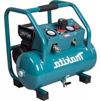
| Product Type | Gas Engine Air Compressor |
| Brand | Makita |
| Model | MAC5500G |
| Power Source | Honda GX160K1QX6-E Gas Engine (4-stroke) |
| Air Tank Capacity | 10 gallons (38 L) |
| Maximum Pressure | 150 psi (10.3 bar) |
| Recommended Engine Oil | SAE 10W-30 (see engine manual) |
| Recommended Compressor Oil | EAOIL 40 (SAE 20W, ISO 68) - 4 liters |
| Compressor Lubrication | Check level before each use; change every 300 hours or 3 months |
| Belt Type | A49-E (V-belt) |
| Warranty | 1 year against defects in material and workmanship |
| Main Functions | Air compression for pneumatic tools, inflation, sandblasting, spraying |
| Routine Maintenance | Check oil level, drain condensation, clean air filter, check belt tension |
| Safety | Safety valve, do not breathe compressed air, wear safety glasses, do not modify tank |
| Main Replacement Parts | Pump PV02A-E, tank 10TT41X5-M-E, regulator 410029-E, safety valve PSV1/4-150-E |
| Repairability | Parts list provided; Makita authorized service centers |
| General Information | Mobile compressor with wheels, recoil start, automatic on/off cycle |
Frequently Asked Questions - MAC5500G MAKITA
User questions about MAC5500G MAKITA
0 question about this device. Answer the ones you know or ask your own.
Ask a new question about this device
Download the instructions for your Compressor in PDF format for free! Find your manual MAC5500G - MAKITA and take your electronic device back in hand. On this page are published all the documents necessary for the use of your device. MAC5500G by MAKITA.
USER MANUAL MAC5500G MAKITA
Portable Gas Compressor Operating Instructions
www.makita.ca
NOTICE
Carefully read this instruction manual before attempting to operate this compressor.
thakita
MAC5500G

www.makita.ca
TABLE OF CONTENTS
SAFETY PRECAUTIONS 4
Cautions 4
Air receiver. 4
Safety valve 4
INSTALLATION & OPERATING INSTRUCTIONS 5
Installation 5
Before operating the air compressor 5
Compressor lubrication 5
Filling compressor with oil 6
Oil changes. 6
Engine lubrication 6
Maintenance 6
Checking Belt Tension 7
OPERATING YOUR AIR COMPRESSOR 8
Engine Gas Driven 8
COMPRESSOR MAINTENANCE SCHEDULE 9
TROUBLESHOOTING 10
WARRANTY 15
FACTORY SERVICE CENTRES 34
PART BREAKDOWNS 35
En Francais 17


CAREFULLY READ THIS INSTRUCTION MANUAL BEFORE ATTEMPTING TO OPERATE THIS COMPRESSOR.
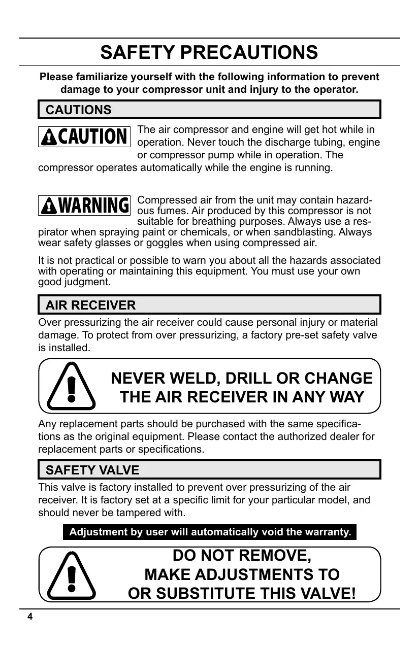
SAFETY PRECAUTIONS
Please familiarize yourself with the following information to prevent damage to your compressor unit and injury to the operator.
CAUTIONS

CAUTION
The air compressor and engine will get hot while in operation. Never touch the discharge tubing, engine or compressor pump while in operation. The
compressor operates automatically while the engine is running.

WARNING
Compressed air from the unit may contain hazardous fumes. Air produced by this compressor is not suitable for breathing purposes. Always use a res
pirator when spraying paint or chemicals, or when sandblasting. Always wear safety glasses or goggles when using compressed air.
It is not practical or possible to warn you about all the hazards associated with operating or maintaining this equipment. You must use your own good judgment.
AIR RECEIVER
Over pressurizing the air receiver could cause personal injury or material damage. To protect from over pressurizing, a factory pre-set safety valve is installed.

NEVER WELD, DRILL OR CHANGE THE AIR RECEIVER IN ANY WAY
Any replacement parts should be purchased with the same specifications as the original equipment. Please contact the authorized dealer for replacement parts or specifications.
SAFETY VALVE
This valve is factory installed to prevent over pressurizing of the air receiver. It is factory set at a specific limit for your particular model, and should never be tampered with.
Adjustment by user will automatically void the warranty.

DO NOT REMOVE, MAKE ADJUSTMENTS TO OR SUBSTITUTE THIS VALVE!
Proper care, maintenance and lubrication ensures longevity. The compressor should always be level for proper lubrication. Use only in a clean, dry, and well-ventilated area. The compressor has heat dissipation fins for proper cooling. Keep the fins and other parts that collect dust clean. Do not place rags or other materials on top of the compressor, as this obstructs cooling and can be a fire hazard.
BEFORE OPERATING THE AIR COMPRESSOR
PLEASE CHECK THE FOLLOWING CAREFULLY:
1) Check to see that nuts and bolts are all snug.
2) Check if the quantity and quality of oil is correct.
3) If the intake filters are dirty, they should be replaced or cleaned.
COMPRESSOR LUBRICATION

ALWAYS CHECK THE OIL LEVEL AND
QUALITY BEFORE START-UP. DO
NOT ADD OR CHANGE OIL WHILE
THE UNIT IS RUNNING. USE ONLY
RECOMMENDED NON-DETERGENT OIL.
RECOMMENDED OIL.
Compressor oil:
EAOIL 10 (1 Litre)
Compressor oil:
- Compressor originally filled with SAE 20W oil (ISO 68)
Compressor oil is a non-detergent mineral oil formulated with additives to help minimize carbon build-up, increase ring life and reduce oil consumption, for use at ambient temperatures of 0^ to 30^ (32^ - 86^) .
OTHER APPROVED OILS.
Regular mineral oils can also be used in Makita compressors. Always use a non-detergent oil with the following specifications:
| AMBIENT TEMPERATURES AT POINT OF OPERATION | SAE VISCOSITY | ISO VISCOSITY |
| -16°C TO 0°C (3.2°F - 32°F) | SAE 10W | ISO 32 |
| 1°C TO 26°C (33.8°F - 78.8°F) | SAE 20W | ISO 68 |
| ABOVE 27°C (80.6°F) | SAE 30W | ISO 100 |
FILLING THE COMPRESSOR WITH OIL
1) Remove the oil filler plug
2) Slowly pour the proper oil into the pump crankcase.
3) Always keep oil level in the middle of the sight glass.
OIL CHANGES
INITIAL OIL CHANGE DUE AT 100 HOURS.
CHANGE OIL EVERY 300 HOURS OR 3 MONTHS WHICHEVER COMES FIRST.
1) Remove the oil drain plug. Allow oil to drain completely.
2) Replace the oil drain plug.
3) Refill with the recommended oil to the proper level.
ENGINE LUBRICATION
Check engine Owner's manual for lubrication and maintenance requirements.
MAINTENANCE
Before doing any maintenance or adjustments to your air compressor, the following safety precautions should be taken:
TURNS OFF ENGINE. WAIT UNTIL ENGINE IS COMPLETELY STOPPED.
DRAIN AIR RECEIVER AND AIR LINES OF AIR PRESSURE.
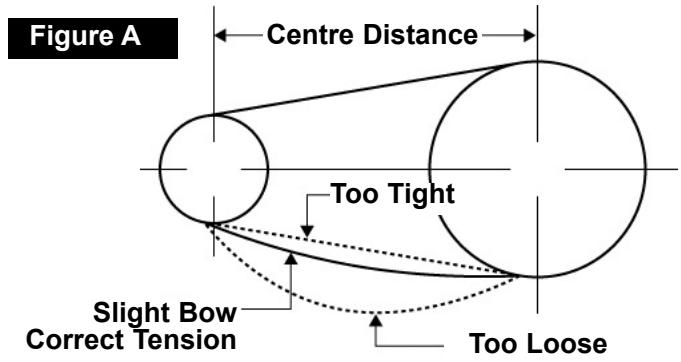
CHECKING BELT TENSION
Adjust belt(s) so when pressure is applied at the center, there is approximately 1/2 slack (see diagram "Figure A" below).
If the belt is installed too tight, the engine might be overloaded. This will cause the engine to overheat. If the belt is installed too loosely, it will slip and excessive wear and vibration will occur.
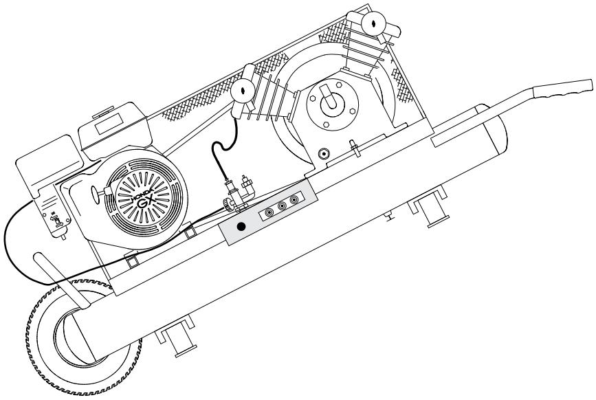
HOW TO INSTALL A NEW BELT IF REQUIRED:
1) Turn off engine. Wait until engine is completely stopped
2) Remove belt guard.
3) Loosen engine bolts and slide engine toward compressor head just enough to allow old belt to be removed.
4) Install proper replacement belt.
5) Slide engine away from compressor head to provide recommended tension as shown in diagram (Figure A.)
6) Align belt using a straight edge ruler against pulley's edge.
7) Fasten engine bolts.
8) Ensure engine and compressor pulley's are secure. Re-check alignment.
9) Re-install belt guard.
10) Belt tension should be checked after 20 hours of operation. Check tension monthly thereafter.
OPERATING YOUR AIR COMPRESSOR
ENGINE - GAS DRIVEN
1) Check entire unit for any damage.
2) Check compressor and engine oil level, fill or add if necessary.
3) Make sure gas tank is filled.
4) Read entire engine manual.
5) Starting the engine.
a) Move fuel lever to the "On" position.
- If engine is cold, move choke lever to the "Closed" position
- If engine is warm, leave choke lever in "Open" position
b) Turn engine switch to "On" position.
c) Pull starter grip lightly until you feel resistance, then pull briskly, return starter grip gently - engine should start, if not repeat.
d) Once the engine starts running, slowly move the choke lever to the "Open" position.
e) With the engine running properly, the compressor fills the air receiver with compressed air, when maximum pressure (set by the pilot valve control) is reached, the engine and compressor will slow down to idle speed, and will return to full RPM when the cut-in pressure is reached. The unit will continue to cycle automatically until turned off.
6) Stopping the engine.
a) Turn engine switch to the "Off" position.
b) Turn the fuel lever to the "Off" position.

ENGINE IDLE SPEED MAY NEED TO BE ADJUSTED, EVEN ON YOUR BRAND NEW UNIT TO COMPENSATE FOR DIFFERENCES IN ALTITUDE. PLEASE CONSULT THE ENGINE OPERATING MANUAL.
MAINTENANCE SCHEDULE

EXTRA CARE SHOULD BE TAKEN TO AVOID PERSONAL INJURIES WITH AUTOMATICALLY CONTROLLED COMPRESSORS
QUARTERLY OR 300 HOURS (Whichever comes first)
INSPECT THE AIR RECEIVER FOR CORROSION OR OTHER DAMAGE.
CHANGE COMPRESSOR OIL.
REPLACE AIR FILTER (MORE OFTEN IF COMPRESSOR IS USED NEAR PAINT SPRAYING OPERATIONS OR IN DUSTY ENVIRONMENTS).
TROUBLE SHOOTING
| PROBLEM | POSSIBLE CAUSE | CORRECTIVE ACTION |
| Will not start | Please refer to Honda manual included | |
| Low pressure | Safety valve leaks. | Replace safety valve. |
| Drain cock open. | Close drain cock. | |
| Loose tubes or fittings. | Tighten fittings. | |
| Dirty or plugged air filter. | Clean or replace as necessary. | |
| Defective unloader valve. | Replace unloader valve. | |
| Oil in discharge | Too much oil in the crank-case. | Drain oil and fill to proper level. |
| Improper oil viscosity. | drain and replace oil | |
| Compressor overheated. | Air pressure regulated too high. | |
| Restricted air filter. | Clean or replace air filter. | |
| Worn piston rings. | Replace piston rings. | |
| Compressor overheats | Dirty compressor head, cylin- der or intercooler. | Clean with compressed air. |
| Clogged inlet filter. | Clean or replace as necessary. | |
| Operating pressure too high. | Reduce operating pressure. | |
| Low oil or wrong oil being used. | Drain and replace oil. | |
| Compressor cycle too long. Proper cycle is 50-60% on Stop/Start operation. | Allow for longer rest between cycles. | |
| Compressor loads & un- loads or idols up & down excessively | Pilot valve differential adjust- ed too close. | Replace worn components as necessary. Make necessary adjustments. |
| Leaks in air system. | Check for leaks. | |
| Worn or loose drive belts | Tighten V-belts or replace | |
| Defective compressor valves. | Replace valves. | |
| Compressor too small for intended use. | Upgrade to larger compressor. |
TROUBLE SHOOTING
| PROBLEM | POSSIBLE CAUSE | CORRECTIVE ACTION |
| Insufficient output, low discharge pressure | Clogged inlet filter. | Clean or replace as necessary. |
| Leaks in air lines, air valves, fittings, etc... | Replace worn components as necessary. | |
| Drive belts slipping. | Tension V-belts. | |
| Drain valve left open. | Close drain valve. | |
| Defective pressure gauge. | Replace pressure gauge. | |
| Leaking head gasket. | Replace head gasket. | |
| Dirty or plugged inter cooler tubes. | Remove and clean inter cooler tubes. | |
| Unloader pilot adjusted too low, or defective. | Make necessary adjustments. | |
| Worn or defective compressor valves. | Replace valves. | |
| Worn piston, worn out rings. | Replace worn parts. | |
| Restrictive check valve. | Clean check valve and replace if necessary. | |
| Compressor incorrectly sized. | Upgrade to larger compressor. | |
| Engine stalls. | Faulty unloader / check valve. | Replace unloader check valve. |
| Low oil in engine | Add oil to engine | |
| Compressor not level. | Level compressor. | |
| Water in crankcase oil gets dirty, rusty valves or cylinders | Cycle too short; compressor does not operate long enough to vaporize condensed moisture during compression. | Allow for longer operating cycle. |
| Compressor operating outside in cold conditions or inlet filter not protected against weather. | Provide adequate protection against extreme weather conditions. |
TROUBLE SHOOTING
| PROBLEM | POSSIBLE CAUSE | CORRECTIVE ACTION |
| System pressure leaking back through check valve when compressor is stopped. | Check and replace check valve if necessary. | |
| Wrong oil being used. | Drain and replace with proper oil | |
| Excessive vibration | Loose compressor, engine or engine guard. | Tighten components. |
| Compressor not level. | Level compressor | |
| Leg bolts over tightened to floor. | Loosen leg bolts. | |
| Excessive discharge pres-sure. | Reduce operating pressure. | |
| Wrong oil being used. | Drain and replace with proper oil. | |
| Loose flywheel, drive, pulley or drive belts. | Tighten loose components and check belts. | |
| Worn connector rods, wrist pin or main bearings. | Check and replace worn parts. | |
| Compressor Knocks | Compressor valves loose or broken. | Check and replace worn or broken valves.. |
| Check valve knocks at low pressure. | Remove and clean check valve. | |
| Compressor uses too much oil | Clogged inlet filter. | Clean inlet filter or replace as necessary. |
| Wrong oil being used, wrong viscosity. | Drain and replace oil. | |
| Oil level too high. | Fill compressor with oil to proper level. | |
| Crankcase breather valve malfunction. | Replace crankcase breather. | |
| Compressor runs unloaded too long | Increase load or stop compres-sor when not needed. Check for air leaks. |
TROUBLE SHOOTING
| PROBLEM | POSSIBLE CAUSE | CORRECTIVE ACTION |
| Compressor operating out-side in cold conditions or inlet filter not protected against weather. | Provide adequate protection against extreme weather conditions. | |
| Worn piston rings. | Replace piston rings. | |
| Piston rings not seated. | See below. | |
| Piston rings not seated. | Allow 100 hours of normal operation for new rings to seat. |
COMPRESSOR MAINTENANCE LOG
| DATE | TYPE OF MAINTENANCE OR REPAIRS |
COMPRESSOR MAINTENANCE LOG
| DATE | TYPE OF MAINTENANCE OR REPAIRS |
| REFLECTED |
MAKITA LIMITED ONE YEAR WARRANTY
WARRANTY POLICY
Every Makita tool is thoroughly inspected and tested before leaving the factory. It is warranted to be free of defects from workmanship and materials for the period of ONE YEAR from the date of original purchase. Should any trouble develop during this one year period, return the COMPLETE tool, freight prepaid, to one of Makita's Factory or Authorized Service Centers. If inspection shows the trouble is caused by defective workmanship or material, Makita will repair, (or at our option, replace), without charge.
This warranty does not apply where:
Repairs have been made or attempted by others;
Repairs are required because of normal wear and tear;
The tool has been abused, misused or improperly maintained;
- Alterations have been made to the tool.
IN NO EVENT SHALL MAKITA BE LIABLE FOR ANY INDIRECT, INCIDENTAL OR CONSEQUENTIAL DAMAGES FROM THE SALE OR USE OF THE PRODUCT. THIS DISCLAIMER APPLIES BOTH DURING AND AFTER THE TERM OF THIS WARRANTY.
- The Makita warranty is the only and entire written warranty given by Makita for the Makita tools. No dealer or his agent or employee is authorized to extend or enlarge upon this warranty by any verbal or written statement or advertisement.
MAKITA DISCLAIMS LIABILITY FOR ANY IMPLIED WARRANTYES, INCLUDING IMPLIED WARRANTYES OF "MERCHANTABILITY" AND "FITNESS FOR A SPECIFIC PURPOSE," AFTER THE ONE YEAR TERM OF THIS WARRANTY.
This Warranty gives you specific legal rights. The provisions contained in this warranty are not intended to limit, modify, take away from, disclaim or exclude any warranties set forth in any provincial legislation. To the extent required by law, the provisions in any provincial of federal legislation with respect to warranties take precedence over the provisions in this warranty.
Makita Corporation
3-11-8, Sumiyoshi-cho,
Anjo, Aichi 446-8502 Japan
Makita Corporation of America
2650 Buford Hwy.
Buford GA 30518
Makita Canada Inc
1950 Forbes Street
Whitby, ON L1N 7B7
thakita
MAC5500G

www makita.ca
thakita
COMPRESSEUR
PORTATIF
Ä ESSENCE
MANUEL
D’UTILISATION
www.makita.ca
AVIS
NE PAS ENLEVER, ALTERER OU REMPLACER CETTE SOUPAPE!
INSTALLATION ET OPÉRATION
INSTALLATION
3-11-8, Sumiyoshi-cho,
Anjo, Aichi 446-8502 Japan
Makita Corporation of America
2650 Buford Hwy.
Buford GA 30518
Makita Canada Inc
1950 Forbes Street
Whitby, ON L1N 7B7
FACTORY SERVICE CENTRES CENTRES DE SERVICE EN USINE
| HEAD OFFICE SIÉGE SOCIAL 1950 Forbes Street, Whitby, ON L1N 7B7 (905) 571-2200 1-800-263-3734 | REGIONAL OFFICE BUREAU RÉGIONAL 11771 Hammersmith Way Richmond, BC V7A 5H6 (604) 272-3104 1-800-663-0909 | REGIONAL OFFICE BUREAU RÉGIONAL 6389 boul Couture St Leonard, PQ H1P 3J5 (514) 323-1223 1-800-361-7049 |
| Alberta #8-6115 4th St. S.E. Calgary, AB T2H 2H9 (403) 243-3995 1-800-267-0445 | Nova Scotia 202 Brownlow Avenue Dartmouth, NS B3B 1T5 (902) 468-7064 1-800-625-4821 | Ontario ... cont'd 317 Adelaide St. S. Unit 117 London, ON N5Z 3L3 (519) 686-3115 1-800-571-0899 |
| 11614 - 149 Street Edmonton, AB T5M 3R5 (780) 455-6644 1-888-455-6644 | Ontario 1950 Forbes Street, Whitby, ON L1N 7B7 (905) 571-2200 1-800-263-3734 | Québec 1140 rue Bégin St. Laurent, PQ H4R 1X1 (514) 745-5025 1-888-745-5025 |
| British Columbia 11771 Hammersmith Way Richmond, BC V7A 5H6 (604) 272-3104 1-800-663-0909 2284 Holdom ave. Burnaby, BC V5B 4Y5 (604) 291-1511 1-877-295-1511 | 6350 Tomken Rd Unit 8 Mississauga, ON L5T 1Y3 (905) 670-7255 1-800-221-9811 | 1200 St. Jean Baptiste Unit 106 Les Saules, PQ G2E 5E8 (418) 871-5720 1-800-663-5757 |
| 203 Colonnade Road Nepean, ON K2E 7K3 (613) 224-5022 1-888-560-2214 | Saskatchewan 206A-2750 Faithful Ave. Saskatoon, SK S7K 6M6 (306) 931-0111 1-888-931-0111 | |
| Manitoba 1670 St. James Street Winnipeg, MB R3H 0L3 (204) 694-0402 1-800-550-5073 |
| PV02A-E Compressor Pump | |||
| Item | Description | Part # | Qty |
| 1 | Intake filter ass'y | 51111-5600-E | 2 |
| 2 | cylinder head | 52122-0101-E | 2 |
| 3 | Lift limiter - discharge valve plate | 51121-3102-E | 4 |
| 4 | Valve seat | 52122-2101-E | 2 |
| 5 | Valve seat to head gasket | 52122-2105-E | 2 |
| 6 | Discharge valve plate | 51121-2103-E | 4 |
| 7 | Intake valve plate | 52122-2103-E | 2 |
| 8 | Valve seat to cylinder gasket | 52122-2104-E | 2 |
| 9 | Piston | 51122-5101-E | 2 |
| 10 | Piston pin /w snap rings | 51122-5112-E | 2 |
| 12 | Connecting rod /w dipper | 51122-5120-E | 2 |
| 14 | Cylinder | 52122-4101-E | 2 |
| 15 | Oil filler cap | 51111-4719-E | 1 |
| 16 | Cylinder to crankcase gasket | 51122-4103-E | 2 |
| 17 | Oil sight glass /w gasket | 51111-4770-E | 1 |
| 18 | Crankcase | 51122-4701-E | 1 |
| 19 | Crankshaft | 51122-4601-E | 1 |
| 20 | Front bearing | 83501-6205-E | 1 |
| 21 | Rear bearing | 83501-6205-E | 1 |
| 22 | Crankcase to rear bearing housing gasket | 51122-4704-E | 1 |
| 23 | Rear bearing housing | 51122-4703-E | 1 |
| 24 | Oil seal | 51122-4708-E | 1 |
| 25 | Crankcase breather | 51111-4761-E | 1 |
| 26 | Flywheel c/w fasteners | 51122-6601-E | 1 |
| 27 | Front bearing housing | 51122-4706-E | 1 |
| 28 | Crankcase to front bearing housing gasket | 51122-4707-E | 1 |
| 29 | Connecting (interstage) tubing | 51122-7710-E | 1 |
| Misc | 1/4" street elbow (oil drain) (Not Shown) | STREL1/4-E | 1 |
| Misc | Rear bearing snap ring (Not Shown) | 83610-113025-E | 1 |
| Misc | Interstage "Y" fitting (Not Shown) | 51121-7702-E | 1 |
| Misc | Interstage "elbow" fitting (Not Shown) | 51112-7701-E | 1 |
| A | Intake filter element kit includes: three (3) intake filter elements | 101000-300-E | 1 |
| B | Valve repair kit includes: valve seat to head gasket (item 5) two(2) outlet valve plates (item 6) intake valve plate (item 7) six(6) valve plate screws valve seat to cylinder gasket (item 8) | 101000-165-E | 2 |
| C | Ring repair kit includes: valve seat to head gasket (item 5) valve seat to cylinder gasket (item 8) two (2) compression rings one (1) oil control ring cylinder to crankcase gasket (item 16) | 101000-265-E | 2 |
| D | Valve Plate Assembly (Not shown) | 52122-2100-E | 2 |
thakita
MAC5500G
www makita.ca
4) Most favored points are / Points favors sont:
Design / Conception
Features / Caracteristiques
Size / Taille
Price /Prix
Repair
Service / Service e
Certificate of warranty / Certificate de garantie
Male Female HommeFemme


Address / Adresse:
City / Ville:
Province:
Postal Code /
Code postal:
Occupation / Profession:
Dealers name and address /