GA6020C - Grinders MAKITA - Free user manual and instructions
Find the device manual for free GA6020C MAKITA in PDF.

| Product type | Angle grinder |
| Brand | MAKITA |
| Model | GA6020C |
| Power source | Mains (alternating current) |
| Voltage | 120 V (depending on model) |
| Frequency | 60 Hz |
| No-load speed | 10,000 rpm |
| Wheel diameter | 150 mm (6 inches) |
| Double insulation | Yes |
| Electric brake | Yes |
| Constant speed control | Yes |
| Soft start | Yes |
| Anti-restart | Yes |
| Overload protection | Yes (automatic power reduction) |
| Indicator light | Yes (green for power, red for anti-restart) |
| Shaft lock | Yes |
| Side handle | Yes, included |
| Auxiliary handle | Yes, included and adjustable |
| Wheel guard | Yes, adjustable |
| Maintenance | Clean ventilation slots, replace brushes |
| Safety | Wear safety glasses, dust mask, hearing protection |
| Main replacement parts | Brushes, inner flange, lock nut, rubber pad |
Frequently Asked Questions - GA6020C MAKITA
User questions about GA6020C MAKITA
0 question about this device. Answer the ones you know or ask your own.
Ask a new question about this device
Download the instructions for your Grinders in PDF format for free! Find your manual GA6020C - MAKITA and take your electronic device back in hand. On this page are published all the documents necessary for the use of your device. GA6020C by MAKITA.
USER MANUAL GA6020C MAKITA
INSTRUCTION MANUAL MANUEL D'INSTRUCTION MANUAL DE INSTRUCCIONES
Angle Grinding Meuleuse d'Angle Esmeriladora de Disco
GA5020
GA5020C
GA5020Y
GA5021C
GA6020
GA6020C
GA6020Y
008074

DOUBLE INSULATION
DOUBLE ISOLATION
DOBLE AISLAMENTO
WARNING:
For your personal safety, READ and UNDERSTAND before using. SAVE THESE INSTRUCTIONS FOR FUTURE REFERENCE.
AVERTISSEMENT:
| Model | GA5020/.GA5020Y | GA5020C/GA5021C | GA6020/GA6020Y | GA6020C |
| Wheel diameter | 125 mm (5") | 125 mm (5") | 150 mm (6") | 150 mm (6") |
| Spindle thread | 5/8" | |||
| No load speed (RPM) | 11,000/min | 10,000/min | 10,000/min | 9,000/min |
| Overall length | 356 mm (14") | 390mm (15-3/8") | 356 mm (14") | 390mm (15-3/8") |
| Net weight | 2.2 kg (4.9 lbs) | 2.4 Kg (5.3 lbs) | 2.2 kg (4.9 lbs) | 2.4 Kg (5.3 lbs) |
- Due to our continuing programme of research and development, the specifications herein are subject to change without notice.
- Note: Specifications may differ from country to country.
USA002-2
GENERAL SAFETY RULES
(For All Tools)
WARNING! Read and understand all instructions.
Failure to follow all instructions listed below, may result in electric shock, fire and/or serious personal injury.
SAVE THESE INSTRUCTIONS.
Work Area
- Keep your work area clean and well lit. Cluttered benches and dark areas invite accidents.
- Do not operate power tools in explosive atmospheres, such as in the presence of flammable liquids, gases or dust. Power tools create sparks which may ignite the dust or fumes.
- Keep bystanders, children, and visitors away while operating a power tool. Distractions can cause you to lose control.
Electrical Safety
- Double insulated tools are equipped with a polarized plug (one blade is wider than the other.) This plug will fit in a polarized outlet only one way. If the plug does not fit fully in the outlet, reverse the plug. If it still does not fit, contact a qualified electrician to install a polarized outlet. Do not change the plug in any way. Double insulation eliminates the need for the three wire grounded power cord and grounded power supply system.
- Avoid body contact with grounded surfaces such as pipes, radiators, ranges and refrigerators. There is an increased risk of electric shock if your body is grounded.
- Do not expose power tools to rain or wet conditions. Water entering a power tool will increase the risk of electric shock.
- Do not abuse the cord. Never use the cord to carry the tools or pull the plug from an outlet.
Keep cord away from heat, oil, sharp edges or moving parts. Replace damaged cords immediately. Damaged cords increase the risk of electric shock.
- When operating a power tool outside, use an outdoor extension cord marked "W-A" or "W". These cords are rated for outdoor use and reduce the risk of electric shock.
Personal Safety
- Stay alert, watch what you are doing and use common sense when operating a power tool. Do not use tool while tired or under the influence of drugs, alcohol, or medication. A moment of inattention while operating power tools may result in serious personal injury.
- Dress properly. Do not wear loose clothing or jewelry. Contain long hair. Keep your hair, clothing, and gloves away from moving parts. Loose clothes, jewelry, or long hair can be caught in moving parts.
- Avoid accidental starting. Be sure switch is off before plugging in. Carrying tools with your finger on the switch or plugging in tools that have the switch on invites accidents.
- Remove adjusting keys or wrenches before turning the tool on. A wrench or a key that is left attached to a rotating part of the tool may result in personal injury.
- Do not overreach. Keep proper footing and balance at all times. Proper footing and balance enables better control of the tool in unexpected situations.
- Use safety equipment. Always wear eye protection. Dust mask, non-skid safety shoes, hard hat, or hearing protection must be used for appropriate conditions. Ordinary eye or sun glasses are NOT eye protection.
Tool Use and Care
-
Use clamps or other practical way to secure and support the workpiece to a stable platform. Holding the work by hand or against your body is unstable and may lead to loss of control.
-
Do not force tool. Use the correct tool for your application. The correct tool will do the job better and safer at the rate for which it is designed.
- Do not use tool if switch does not turn it on or off. Any tool that cannot be controlled with the switch is dangerous and must be repaired.
- Disconnect the plug from the power source before making any adjustments, changing accessories, or storing the tool. Such preventive safety measures reduce the risk of starting the tool accidentally.
- Store idle tools out of reach of children and other untrained persons. Tools are dangerous in the hands of untrained users.
- Maintain tools with care. Keep cutting tools sharp and clean. Properly maintained tools with sharp cutting edges are less likely to bind and are easier to control.
- Check for misalignment or binding of moving parts, breakage of parts, and any other condition that may affect the tool's operation. If damaged, have the tool serviced before using. Many accidents are caused by poorly maintained tools.
- Use only accessories that are recommended
by the manufacturer for your model. Accessories that may be suitable for one tool, may become hazardous when used on another tool.
SERVICE
- Tool service must be performed only by qualified repair personnel. Service or maintenance performed by unqualified personnel could result in a risk of injury.
- When servicing a tool, use only identical replacement parts. Follow instructions in the Maintenance section of this manual. Use of unauthorized parts or failure to follow Maintenance instructions may create a risk of electric shock or injury.
USE PROPER EXTENSION CORD. Make sure your extension cord is in good condition. When using an extension cord, be sure to use one heavy enough to carry the current your product will draw. An undersized cord will cause a drop in line voltage resulting in loss of power and overheating. Table 1 shows the correct size to use depending on cord length and nameplate ampere rating. If in doubt, use the next heavier gage. The smaller the gage number, the heavier the cord.
Table 1: Minimum gage for cord
| Ampere Rating | Volts | Total length of cord in feet | ||||
| 120 V | 25 ft. | 50 ft. | 100 ft. | 150 ft. | ||
| More Than | Not More Than | AWG | ||||
| 0 | 6 | 18 | 16 | 16 | 14 | |
| 6 | 10 | 18 | 16 | 14 | 12 | |
| 10 | 12 | 16 | 16 | 14 | 12 | |
| 12 | 16 | 14 | 12 | Not Recommended | ||
000173
USB005-4
SPECIFIC SAFETY RULES
DO NOT let comfort or familiarity with product (gained from repeated use) replace strict adherence to grinder safety rules. If you use this tool unsafely or incorrectly, you can suffer serious personal injury.
- Always use proper guard with grinding wheel. A guard protects operator from broken wheel fragments.
- Accessories must be rated for at least the speed recommended on the tool warning label. Wheels and other accessories running over rated speed can fly apart and cause injury.
- Hold tool by insulated gripping surfaces when performing an operation where the cutting tool
may contact hidden wiring or its own cord. Contact with a "live" wire will make exposed metal parts of the tool "live" and shock the operator.
- When using depressed center grinding wheels, be sure to use only fiberglass-reinforced wheels.
- Always use safety glasses or goggles. Ordinary eye or sun glasses are NOT safety glasses.
- Check the wheel carefully for cracks or damage before operation. Replace cracked or damaged wheel immediately. Run the tool (with guard) at no load for about a minute, holding tool away from others. If wheel is flawed, it will likely separate during this test.
- Use only flanges specified for this tool.
- Be careful not to damage the spindle, the
flange (especially the installing surface) or the lock nut. Damage to these parts could result in wheel breakage.
-
NEVER use tool with wood cutting blades or other sawblades. Such blades when used on a grinder frequently kick and cause loss of control leading to personal injury.
-
Hold the tool firmly.
- Keep hands away from rotating parts.
- Make sure cord is clear of wheel. Do not wrap cord around your arm or wrist. If control of tool is lost, cord may become wrapped around you and cause personal injury.
- Make sure the wheel is not contacting the workpiece before the switch is turned on.
- Before using the tool on an actual workpiece, let it run for a while. Watch for vibration or wobbling that could indicate poor installation or a poorly balanced wheel.
- Use the specified surface of the wheel to perform the grinding.
- Watch out for flying sparks. Hold the tool so that sparks fly away from you and other persons or flammable materials.
- Do not leave the tool running. Operate the tool only when hand-held.
- Do not touch the workpiece immediately after operation; it may be extremely hot and could burn your skin.
- ALWAYS wear proper apparel including long sleeve shirts, leather gloves and shop aprons to protect skin from contact with hot grindings.
- Use of this tool to grind or sand some products, paints and wood could expose user to dust containing hazardous substances. Use appropriate respiratory protection.
- After using the tool, make sure the wheel rotation comes to a complete stop before setting the tool down. Setting the tool down with the wheel rotating can cause personal injury.
SAVE THESE INSTRUCTIONS.
WARNING:
MISUSE or failure to follow the safety rules stated in this instruction manual may cause serious personal injury.
USD295-1
Symbols
The followings show the symbols used for tool.
V
volts
A
amperes

alternating current

alternating or direct current
n。
no load speed

Class II Construction
.../min r/min
- revolutions or reciprocation per minute
FUNCTIONAL DESCRIPTION
CAUTION:
Always be sure that the tool is switched off and unplugged before adjusting or checking function on the tool.
Shaft lock
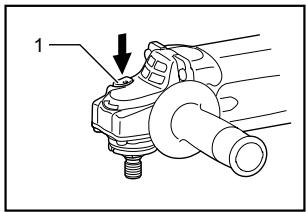
- Shaft lock
007991
CAUTION:
- Never actuate the shaft lock when the spindle is moving. The tool may be damaged.
Press the shaft lock to prevent spindle rotation when installing or removing accessories.
Switch action
CAUTION:
- Before plugging in the tool, always check to see that the switch trigger actuates properly and returns to the "OFF" position when released.
For tool with type A switch trigger
007992
- Lock button / Lock-off button
- Switch trigger (typeA)
For tool without lock button and lock-off button
To start the tool, simply pull the switch trigger. Release the switch trigger to stop.
For tool with lock-off button
To prevent the switch trigger from being accidentally pulled, a lock-off button is provided.
To start the tool, depress the lock-off button and pull the switch trigger. Release the switch trigger to stop.
For tool with typeB switch trigger
008415
- Lock lever
- Switch trigger (type B)
For tool with the lock-on switch
To start the tool, simply pull the switch trigger (A). Release the switch trigger to stop. For continuous operation, pull the switch trigger (A) and then push in the lock lever (B). To stop the tool from the locked position, pull the switch trigger (A) fully, then release it.
For tool with the lock-off switch
To prevent the switch trigger from accidentally pulled, a lock lever is provided. To start the tool, push in the lock lever (B) and then pull the switch trigger (A). Release the switch trigger to stop.
For tool with the lock on and lock-off switch
To prevent the switch trigger from accidentally pulled, a lock lever is provided. To start the tool, push in the lock lever (B) and then pull the switch trigger (A). Release the switch trigger to stop. For continuous operation, push in the lock lever (B), pull the switch trigger and then push the lock lever further in (B). To stop the tool from the locked position, pull the switch trigger (A) fully, then release it.
Electric brake
This tool is equipped with an electric wheel brake. If the tool consistently fails to quickly stop wheel after switch trigger release, have tool serviced at a Makita service center.
Electronic function
Constant speed control (For models GA5020C/GA5021C/GA6020C)
Possible to get fine finish, because the rotating speed is kept constantly even under the loaded condition.
- Additionally, when the load on the tool exceeds admissible levels, power to the motor is reduced to protect the motor from overheating. When the load returns to admissible levels, the tool will operate as normal.
Soft start feature
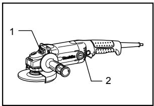
Soft start because of suppressed starting shock. Indication lamp
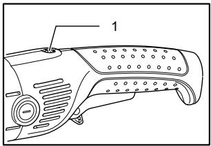
1. Indication lamp
008416
The indication lamp lights up green when the tool is plugged. If the indication lamp does not light up, the mains cord or the controller may be defective. The indication lamp is lit but the tool does not start even if the tool is switched on, the carbon brushes may be worn out, or the controller, the motor or the ON/OFF switch may be defective.
Unintentional restart proof
Even locking lever keeping the switch trigger depressed (Lock-on position) does not allow the tool to restart even when the tool is plugged.
At this time, the indication lamp flickers red and shows the unintentional restart proof device is on function.
To cancel the unintentional restart proof, pull the switch trigger fully, then release it.
ASSEMBLY
CAUTION:
Always be sure that the tool is switched off and unplugged before carrying out any work on the tool.
Installing side grip (handle)
CAUTION:
Always be sure that the side grip is installed securely before operation.
007993
Screw the side grip securely on the position of the tool as shown in the figure.
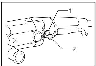
Installing loop handle (Accessory)
CAUTION:
Always be sure that the loop handle is installed securely before operation.
008049
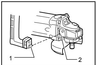
- Protrusion of loop handle
- Matching hole in gear housing
Always install the loop handle on the tool before operation. Hold the tool's switch handle and the loop handle firmly with both hands during operation.
Install the loop handle so that its protrusion will fit into the matching hole in the gear housing.
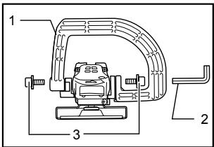
Install the bolts and tighten them with the hex wrench. The loop handle can be installed in two different directions as shown in the figures whichever is convenient for your work.
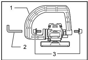
- Loop handle
- Hex wrench
- Bolt
008048
- Loop handle
- Hex wrench
- Bolt
Installing or removing wheel guard
CAUTION:
- When using a depressed center grinding wheel/Multi-disc, wire wheel brush or cut-off wheel, the wheel guard must be fitted on the tool so that the closed side of the guard always points toward the operator.
For tool with locking screw type wheel guard
007994
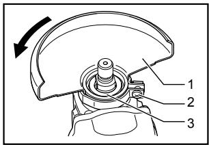
- Wheel guard
- Screw
- Bearing box
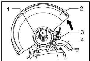
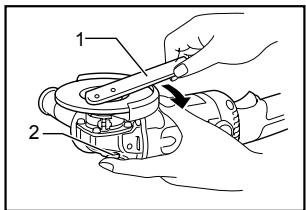
Mount the wheel guard with the protrusion on the wheel guard band aligned with the notch on the bearing box. Then rotate the wheel guard around 180 degrees counterclockwise. Be sure to tighten the screw securely. To remove wheel guard, follow the installation procedure in reverse.
For tool with clamp lever type wheel guard
008047
008343
- Bearing box
2.Wheel guard - Screw
- Lever
008344
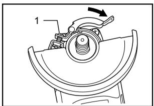
1. Screw
Loosen the lever on the wheel guard after loosening the screw. Mount the wheel guard with the protrusion on the wheel guard band aligned with the notch on the bearing box. Then rotate the wheel guard around to the position shown in the figure. Tighten the lever to fasten the wheel guard. If the lever is too tight or too loose to fasten the wheel guard, loosen or tighten the screw to adjust the tightening of the wheel guard band.
To remove wheel guard, follow the installation procedure in reverse.
Installing or removing depressed center grinding wheel/Multi-disc (accessory)
WARNING:
Always use supplied guard when depressed center grinding wheel/Multi-disc is on tool. Wheel can shatter during use and guard helps to reduce chances of personal injury.
007995
- Lock nut
- Depressed center grinding wheel/Multi-disc
- Inner flange
For USA/Canada only
008053
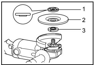
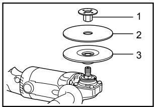
- Lock nut
- Depressed center grinding wheel/Multi-disc
- Inner flange
Mount the inner flange onto the spindle. Fit the wheel/disc on the inner flange and screw the lock nut onto the spindle.
To tighten the lock nut, press the shaft lock firmly so that the spindle cannot revolve, then use the lock nut wrench and securely tighten clockwise.
007996
- Lock nut wrench
- Shaft lock
To remove the wheel, follow the installation procedure in reverse.
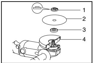
Installing or removing abrasive disc (optional accessory)
NOTE:
- Use sander accessories specified in this manual. These must be purchased separately.
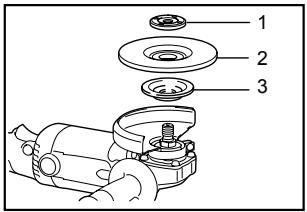
- Lock nut
- Abrasive disc
- Rubber pad
Mount the rubber pad onto the spindle. Fit the disc on the rubber pad and screw the lock nut onto the spindle. To tighten the lock nut, press the shaft lock firmly so that the spindle cannot revolve, then use the lock nut wrench and securely tighten clockwise.
To remove the disc, follow the installation procedure in reverse.
OPERATION
WARNING:
It should never be necessary to force the tool. The weight of the tool applies adequate pressure. Forcing and excessive pressure could cause dangerous wheel breakage.
- ALWAYS replace wheel if tool is dropped while grinding.
- NEVER bang or hit grinding disc or wheel onto work.
- Avoid bouncing and snagging the wheel, especially when working corners, sharp edges etc. This can cause loss of control and kickback.
- NEVER use tool with wood cutting blades and other sawblades. Such blades when used on a grinder frequently kick and cause loss of control leading to personal injury.
CAUTION:
- Never switch on the tool when it is in contact with the workpiece, it may cause an injury to operator.
Always wear safety goggles or a face shield during operation.
After operation, always switch off the tool and wait until the wheel has come to a complete stop before putting the tool down.
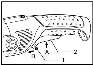
Grinding and sanding operation
007998
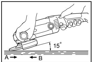
ALWAYS hold the tool firmly with one hand on rear handle and the other on the side handle. Turn the tool on and then apply the wheel or disc to the workpiece.
In general, keep the edge of the wheel or disc at an angle of about 15 degrees to the workpiece surface.
During the break-in period with a new wheel, do not work the grinder in the B direction or it will cut into the workpiece. Once the edge of the wheel has been rounded off by use, the wheel may be worked in both A and B direction.
Operation with wire cup brush (optional accessory)
CAUTION:
- Check operation of brush by running tool with no load, insuring that no one is in front of or in line with brush.
- Do not use brush that is damaged, or which is out of balance. Use of damaged brush could increase potential for injury from contact with broken brush wires.
008002
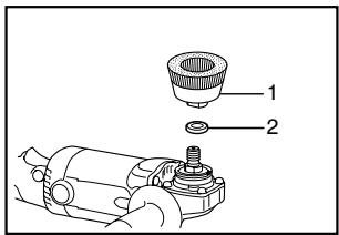
- Wire cup brush
- Urethane washer
Unplug tool and place it upside down allowing easy access to spindle. Remove any accessories on spindle. Mount urethane washer then thread wire cup brush onto spindle and tighten with supplied wrench. When using brush, avoid applying too much pressure which causes over bending of wires, leading to premature breakage.
NOTE:
- When using wire cup brush, mount urethane washer to the spindle. It will make it easier to remove wire cup brush.
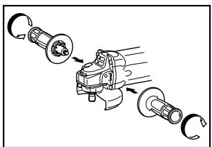
Operation with wire wheel brush (optional accessory)
CAUTION:
- Check operation of wire wheel brush by running tool with no load, insuring that no one is in front of or in line with the wire wheel brush.
- Do not use wire wheel brush that is damaged, or which is out of balance. Use of damaged wire wheel brush could increase potential for injury from contact with broken wires.
- ALWAYS use guard with wire wheel brushes, assuring diameter of wheel fits inside guard. Wheel can shatter during use and guard helps to reduce chances of personal injury.
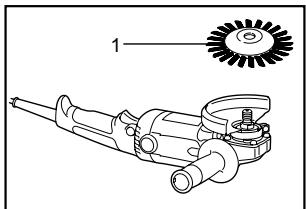
007999
1. Wire wheel brush
Unplug tool and place it upside down allowing easy access to spindle. Remove any accessories on spindle. Thread wire wheel brush onto spindle and tighten with the wrenches.
When using wire wheel brush, avoid applying too much pressure which causes over bending of wires, leading to premature breakage.
Operation with abrasive cut-off wheel (optional accessory)
008054
- Lock nut
- Abrasive cut-off wheel
- Inner flange
- Wheel guard for cut-off wheel
008001
- Exhaust vent
- Inhalation vent
Replacing carbon brushes
- Limit mark
WARNING:
- When using an abrasive cut-off wheel, be sure to use only the special wheel guard designed for use with cut-off wheels.
NEVER use cut-off wheel for side grinding. - Do not "jam" the wheel or apply excessive pressure. Do not attempt to make an excessive depth of cut. Overstressing the wheel increases the loading and susceptibility to twisting or binding of the wheel in the cut and the possibility of kickback, wheel breakage and overheating of the motor may occur.
- Do not start the cutting operation in the workpiece. Let the wheel reach full speed and carefully enter into the cut moving the tool forward over the workpiece surface. The wheel may bind, walk up or kickback if the power tool is started in the workpiece.
During cutting operations, never change the angle of the wheel. Placing side pressure on the cut-off wheel (as in grinding) will cause the wheel to crack and break, causing serious personal injury.
MAINTENANCE
CAUTION:
Always be sure that the tool is switched off and unplugged before attempting to perform inspection or maintenance.
The tool and its air vents have to be kept clean. Regularly clean the tool's air vents or whenever the vents start to become obstructed.
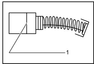
001145
Remove and check the carbon brushes regularly. Replace when they wear down to the limit mark. Keep the carbon brushes clean and free to slip in the holders. Both carbon brushes should be replaced at the same time. Use only identical carbon brushes.
Use a screwdriver to remove the brush holder caps. Take out the worn carbon brushes, insert the new ones and secure the brush holder caps.
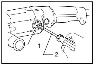
008000
- Brush holder cap
- Screwdriver
After replacing brushes, plug in the tool and break in brushes by running tool with no load for about 10 minutes. Then check the tool while running and electric brake operation when releasing the switch trigger. If electric brake is not working well, ask your local Makita service center for repair. (For models GA5020/GA6020) To maintain product SAFETY and RELIABILITY, repairs, any other maintenance or adjustment should be performed by Makita Authorized or Factory Service Centers, always using Makita replacement parts.
ACCESSORIES
CAUTION:
These accessories or attachments are recommended for use with your Makita tool specified in this manual. The use of any other accessories or attachments might present a risk of injury to persons. Only use accessory or attachment for its stated purpose.
- Your tool is supplied with a guard for use with a depressed center grinding wheel, multi-disc and wire wheel brush. A cut-off wheel can also be used with an optional guard. If you decide to use your Makita grinder with approved accessories which you purchase from your Makita distributor or factory service center, be sure to obtain and use all necessary fasteners and guards as recommended in this manual. Your failure to do so could result in personal injury to you and others.
If you need any assistance for more details regarding these accessories, ask your local Makita Service Center.
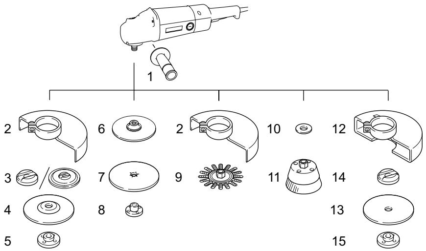
| GA5020/GA5020C/GA5021C/GA5020Y | GA6020/GA6020C/GA6020Y | |
| 1 | Grip 36 | |
| 2 | Wheel guard | |
| 3 | Inner flange 45 | Inner flange 82 |
| 4 | Depressed center grinding wheel/Multi-disc | |
| 5 | Lock nut 5/8-45 | |
| 6 | Rubber pad 115 | |
| 7 | Abrasive disc | |
| 8 | Sanding lock nut 5/8-48 | |
| 9 | Wire wheel brush | |
| 10 | Urethane washer 14 | |
| 11 | Wire cup brush | |
| 12 | Wheel guard (For cut-off wheel) | |
| 13 | Cut-off wheel | |
| 14 | Inner flange 45 | Inner flange 48 |
| 15 | Lock nut 5/8-45 | Lock nut 5/8-48 |
| - | Lock nut wrench 28 | |
| - | Loop handle | |
| - | Dust cover | |
MAKITA LIMITED ONE YEAR WARRANTY
Warranty Policy
Every Makita tool is thoroughly inspected and tested before leaving the factory. It is warranted to be free of defects from workmanship and materials for the period of ONE YEAR from the date of original purchase. Should any trouble develop during this one year period, return the COMPLETE tool, freight prepaid, to one of Makita's Factory or Authorized Service Centers. If inspection shows the trouble is caused by defective workmanship or material, Makita will repair (or at our option, replace) without charge.
This Warranty does not apply where:
- repairs have been made or attempted by others:
- repairs are required because of normal wear and tear:
the tool has been abused, misused or improperly maintained:
alterations have been made to the tool.
IN NO EVENT SHALL MAKITA BE LIABLE FOR ANY INDIRECT, INCIDENTAL OR CONSEQUENTIAL DAMAGES FROM THE SALE OR USE OF THE PRODUCT. THIS DISCLAIMER APPLIES BOTH DURING AND AFTER THE TERM OF THIS WARRANTY.
MAKITA DISCLAIMS LIABILITY FOR ANY IMPLIED WARRANTYES, INCLUDING IMPLIED WARRANTYES OF "MERCHANTABILITY" AND "FITNESS FOR A SPECIFIC PURPOSE," AFTER THE ONE YEAR TERM OF THIS WARRANTY.
This Warranty gives you specific legal rights, and you may also have other rights which vary from state to state. Some states do not allow the exclusion or limitation of incidental or consequential damages, so the above limitation or exclusion may not apply to you. Some states do not allow limitation on how long an implied warranty lasts, so the above limitation may not apply to you.
FRANÇAIS SÉCURIFICATIONS
| Modèle | GA5020/.GA5020Y | GA5020C/GA5021C | GA6020/GA6020Y | GA6020C |
| Diamètre de la meule | 125 mm (5") | 125 mm (5") | 150 mm (6") | 150 mm (6") |
| Filetage de l'arbre | 5/8" | |||
| Vitesse à vide (T/MIN) | 11,000/min | 10,000/min | 10,000/min | 9,000/min |
| Longueur totale | 356 mm (14") | 390mm (15-3/8") | 356 mm (14") | 390mm (15-3/8") |
| Poids net | 2.2 kg (4.9 lbs) | 2.4 Kg (5.3 lbs) | 2.2 kg (4.9 lbs) | 2.4 Kg (5.3 lbs) |
construction, catalogue II
... /min
Some dust created by power sanding, sawing, grinding, drilling, and other construction activities contains chemicals known to the State of California to cause cancer, birth defects or other reproductive harm. Some examples of these chemicals are:
- lead from lead-based paints,
crystalline silica from bricks and cement and other masonry products, and - arsenic and chromium from chemically-treated lumber.
Your risk from these exposures varies, depending on how often you do this type of work. To reduce your exposure to these chemicals: work in a well ventilated area, and work with approved safety equipment, such as those dust masks that are specially designed to filter out microscopic particles.
< USA solamente >
ADVERTENCIA
3-11-8, Sumiyoshi-cho,
Anjo, Aichi 446-8502 Japan