
PCM 1024A - Remote control equipment FUTABA - Free user manual and instructions
Find the device manual for free PCM 1024A FUTABA in PDF.
| Product type | Digital proportional radio control equipment |
| Brand | FUTABA |
| Model | PCM 1024A (FP-9VAP) |
| Number of channels | 9 channels |
| Frequency | 72 MHz, 53 MHz, 50 MHz |
| Modulation | FM-PCM / PPM selectable |
| Transmitter power supply | Internal NiCd battery 9.6 V / 500 mAh |
| Receiver power supply | NiCd battery 4.8 V (shared with servos) |
| Transmitter current consumption | 230 mA |
| Receiver dimensions | 63.0 x 37.8 x 24.1 mm |
| Receiver weight | 45 g |
| Servo torque (FP-S9101) | 3.1 kg-cm (69.5 oz-in) |
| Servo speed (FP-S9101) | 0.16 sec / 60° |
| Servo torque (FP-S5101) | 4.0 kg-cm (55.6 oz-in) |
| Servo speed (FP-S5101) | 0.24 sec / 60° |
| Programmable functions | Servo reversing, Failsafe, ATV, AFR, Dual Rate, Exponential, Programmable mixing, Snap Roll, Wing types, Air Brake, Pitch Control, Trim Memory, and more |
| Display | Graphic LCD screen |
| Model memory | 6 models with name |
| Backup | Lithium battery 5 years |
| Safety | Low battery alarm, Failsafe, Battery Failsafe, auto power off 30 min |
| Maintenance and cleaning | Keep dry, avoid oil and dust, clean with a soft cloth |
| Repairability | Spare parts available through Futaba after-sales service |
Frequently Asked Questions - PCM 1024A FUTABA
User questions about PCM 1024A FUTABA
0 question about this device. Answer the ones you know or ask your own.
Ask a new question about this device
Download the instructions for your Remote control equipment in PDF format for free! Find your manual PCM 1024A - FUTABA and take your electronic device back in hand. On this page are published all the documents necessary for the use of your device. PCM 1024A by FUTABA.
USER MANUAL PCM 1024A FUTABA
Thank you for purchasing a FUTABA digital proportional radio control set Please read this manual carefully before using your set. The last page of this manual is a three-part foldout. Refer to thisfoldout when reading the manual.
TABLE OF CONTENTS
FEATURES 1-2
SETCONTENTS. 3
RATINGS 3
RECEIVER AND SERVOS 4-5
Nicd BATTERY CHARGING 6
BASIC TRANSMITTER T9VAP CONTROL. 7-9
TIMER 10-11
TACHOMETER 12
LOW BATTERY WARNING 12
BACK-UPWARNING 13
SYSTEM PROGRAMMING
EDIT PROGRAM KEY 13
REVERSE 14
FAILSAFE(F/S) 14-15
ADJUSTABLE TRAVEL VOLUME (ATV) 16
ADJUSTABLE FUNCTION RATE (AFR) 17
DUAL RATE (D/R) 18-19
END SOFT KEY 19
EXPONENTIAL (EXP) 20-21
MIXING 22
PROGRAMMABLE MIXING 23-29
SNAP ROLL 30-31
WING TYPE 32
(1) AIL DIFF (AILERON DIFFERENTIAL) 32-33
(2) FLAPERON 33-34
(3) ELEVON 35
(4) V-TAIL 36
AIR BRAKE 37-38
PITCH CONTROL MIXING
(VARIABLE PITCH) 39
ELEVATOR/FLAPMIXING. 40
TRIM (CROSS TRIM, TRIM MEMORY) 41-42
PARAMETERS (SERVO TEST, MIXING MODE,
PCM/PPM, D/R SW DIR, 9CH SW POSITION) 43
MODEL SELECTION 44-45
MODEL COPY 46
NAME 47
SERVO (TEST MODE) 48
RESET 49
SERVO EXPLODED VIEW 50
SPLINED HORNS 51
SOFT MAP 1 52-53
T9VAP TRANSMITTER CONTROLS 54-55
SOFT MAP 2 56
WARNING:
The FUTABA PCM1024A system has numerous operating features and is designed for serious and experienced radio control hobbyists. Newcomers to the hobby should seek advice and assistance in operating this set. Improper operation can result in property damage and/or serious personal injury. Radio control model airplanes are not toys. If you are new to the hobby, it is recommended that you contact your local hobby dealer regarding clubs and individuals offering advice and assistance to beginners.
FEATURES
The PCM1024A was specially-developed to meet the needs of the serious and demanding R/C hobbyist. Numerous features make this system adaptable to a wide variety of complex radio control stunt and scale aircraft. This is the most advanced system available for FAI Precision Acrobatic (F3A) competition. The built-in microprocessor utilizing PCM (Pulse Code Modulation) makes this set very versatile and extremely noise and deadpoint resistant.
Please read this manual carefully before using your set.
TRANSMITTER FP-T9VAP
- Programming data is displayed pictorially and graphically on a large, easy-to-read LCD (Liquid Crystal Display) panel. Programming and Cursor keys allow convenient adjustment of aircraft functions.
- "1024" Channel Resolution: New 1024 PCM encoder format provides unexcelled servo resolution and response time.
- RF module uses a narrow band modulation circuit and PCM transmission.
- Precise control is made possible by.. three different endpoint adjustment functions: Adjustable Travel Volume (ATV), Adjustable Function Rate (AFR), and Adjustable Trim Rate.
- Dual Rates, Exponential, and Variable Trace Rate (VTR) functions provide unlimited flexibility in "fine tuning" aircraft control response.
- Numerous special control mixing functions have been refined for FAI R/C aerobatics (F3A). Four programmable mixing circuits provide tremendous versatility in adapting the system to diverse and specialized applications.
- Throttle -> pitch control mixing circuit is designed for use with variable-pitch propellers to maximize engine performance and reduce noise.
- Idle-Up lever: The engine idle speed can be independently adjusted during throttle pitch control mixing.
- Pitch control lever: High pitch position on variable-pitch propellers is trimmable with the lever.
- Snap roll program allows four different programmable snap rolls to be performed at the touch of a button.
- Programming for up to six different models (including model name) can be stored in the transmitter memory. Memorized data is protected by a 5 year lithium battery.
-
Accessory "sub-trimmers" are provided on the transmitter front for convenient field adjustment of frequently-used functions.
-
Trim positions for each model can be memorized by the Trim Memory function, allowing the trim levers and sub trimmers to be returned to neutral. Neutral positions can be reproduced in the future, or copied onto another model program if desired.
- The Tachometer function measures engine rpm by means of a built-in sensor.
- Speed can be measured for 1 to 5 bladed propellers.
- Digital alarm/timer has UP, DOWN, and RHYTHMIC timing modes
- Integrating (Total) Timer monitors total transmitter ON time.
- Ball bearing open gimbal sticks, angled switches, and "human-engineered" transmitter case enhance the feeling of comfort and precision in transmitter operation.
- "Quick Change" Nicd battery pack is easily accessible by means of a convenient panel on the transmitter back.
- Power Off function turns off the transmitter power automatically if the controls are not operated for 30 minutes.
- PCM or standard PPM operation can be selected. (Allows operation of standard FM receivers on the same frequency.)
- DSC (Direct Servo Control): The DSC cord allows operation of all servos without turning on the transmitter. The voltage of the transmitter and receiver Nicd batteries can also be read simultaneously using the cord.
- Servo reversing is available on all channels.
- Auto Dual Rate: If desired, aileron, elevator, and rudder dual rate can be turned ON and OFF automatically, according to throttle stick position.
- Stick length and angle is easily adjusted.
- Knobs and levers are conveniently located.
RECEIVER FP-R129DP
- Extremely quick response, high resolution, and high reliability are achieved with a newly-developed, low voltage PCM decoder.
- RF amplifier and monolithic IF amp designed for high sensitivity.
- Dual conversion "1991" design with ultra narrow-band ceramic filter is immune to adjacent band interference (cross modulation interference, mutual modulation interference) and spark noise.
- Fail Safe and Battery Fail Safe functions provide greater safety and reliability.
Servo Hold function eliminates "glitches" during momentary signal losses or strong interference.
- Gold-plated connector pins provide positive contact.
- DSC System: Operation of all servos is possible without turning on the transmitter by connecting the accessory cord directly to the C terminal of the receiver.
SERVO FP-S9101 +S5101
- High torque and high speed water-and dustproof servo with highest-quality coreless motor.
Output torque 3.1 kg-cm (69.5 oz.-in.). Operating speed 0.16 sec/60°. Output torque 4.0 kg-cm (55.6 oz.-in.). Operating speed 0.24 sec/60°. - New indirect drive potentiometer improves vibration and shock resistance and neutral precision tremendously.
-
Futaba custom 1C provides high starting torque, narrow dead band, and excellent trackability. Neutral holding force is also improved substantially.
-
Fiberglass reinforced PBT (polybutylene terephthalate) molded servo case is mechanically strong and invulnerable to glow fuel.
- Strong polyacetal resin, ultra precision servo gears ensure smooth operation, positive neutral, and minimal backlash.
- Fiberglass reinforced epoxy resin PC board with thru-the-hole plating improves reliability against shock and vibration.
- Seven special adjustable splined output arms.
-SETCONTENTS
| Model | FP-9VAP |
| Transmitter | FP-T9VAP x 1 |
| Receiver | FP-R129DPx 1 |
| Servos | FP-S9101 x4,orS5101 x4 |
| Switch | SSW-J x 1 |
| Nicd Battery | NR-4J x 1 |
| Misc. | Battery charger, extension cord, DSC cord, CHG adaptor, DSC-CHG cord, frequency flag, spare output arms, neck strap, screws |
RATINGS
Transmitter FP-T9VAP
Operating System : Two-stick, 9 Channel, PCM
Transmitting Frequency: 72MHz, 53MHz, 50MHz
Modulation : FM- PCM/PPM selectable.
Power Requirement : 9.6 volt (8/500mAh) internal Nicd battery
Current Drain : 230mA
Receiver FP-R129DP
Receiving Frequencies 72MHz, 53MHz, and 50MHz
Intermediate Frequency 1st IF : 10.7MHz
2nd IF:455kHz
Power Requirement 4.8 volt Nicd battery (shared w/servos)
Current Drain 35mA (4.8V reception)
Dimensions 63.0x37.8x24.1mm
Weight 45g(1.6oz.)
Receiving Range 500m (1,500 ft.) ground 1,000m (3,000ft.) air
(When FP-T9VAP used under
best radiowave conditions)
Charger PBC-8B (2)
Input Voltage : 120VAC, 60Hz, 4W
Output Voltage : TX side 9.6V, 50mA
RX side 4.8V, 50mA
Servo FP-S9101 -5101
Control System : + pulse width control 1520uS neutral
Operating Angle : Each direction from neutral - 45 or greater (including trim)
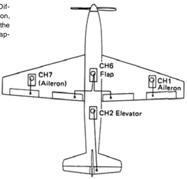
- RECEIVERS AND SERVOS
Receiver, servo, switch, and battery connections
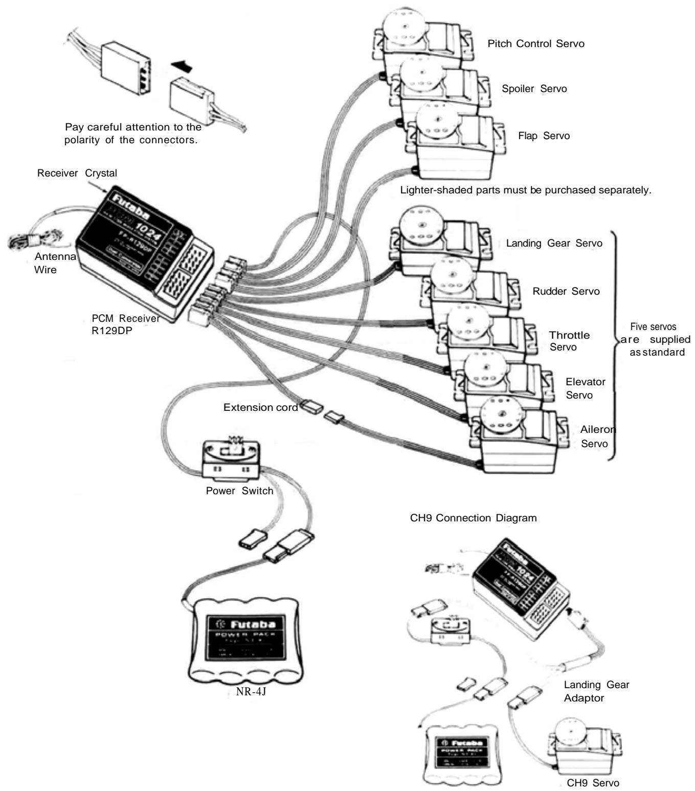
- AIL (AILERON)
- ELV (ELEVATOR)
- THR (THROTTLE)
- RUD (RUDDER)
- GER (GEAR)
- FLP (FLAP)
- SPO (SPOILER)
- PIT (PROPELLER PITCH)
- CH9 (CHANNEL 9)
PRECAUTIONS
NOTE: A separate servo on each aileron will allow use of special transmitter control mixing and differen-tia/ functions.
- Connect the receiver, servos, switch harness, etc. as shown in the figure. Extend the transmitter and receiver antennas to their full length. Turn on the transmitter power switch, then turn on the receiver power switch. The servos will go to their neutral position. Move the transmitter sticks one at a time to check that each servo follows its control stick movement.
- Connect pushrods and linkages to the servos and check that the direction of travel of each servo matches the direction of movement of its control stick. If a servo does not move in the proper direction, use the servo reversing function (See page 14).
- Operate each servo to its full extent, and check for binding and/or excess slop in the linkage or pushrod. Unreasonable force on the servo arm may damage the servo and will drain the batteries very quickly.
- Adjust servo output arms and aircraft control linkage as necessary so that each servo moves smoothly throughout its full range of travel, even when the control stick and trim lever are operated simultaneously in the same direction.
- Be alert for possible sources of electrical noise. This set is noise-resistant, but the use of noiseless parts is recommended.
-
When installing the switch harness, make sure that the switch can move smoothly, to its full extent in each direction without binding. Install the switch where it will not be exposed to engine oil, dust, dirt, etc. The switch can be installed inside the fuselage and operated from the outside with a piece of wire.
-
Do NOT shorten the receiver antenna or fold it back along its length.
- When installing the servos, tighten the mounting screws so that the rubber grommets are compressed slightly. If the screws are too tight, the vibration-dampening effect of the grommets will be lost and servo failure may occur.
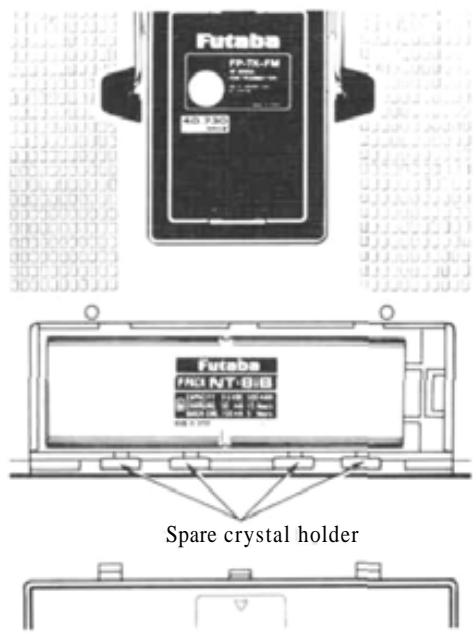
- The crystal can be changed without opening the receiver case. Always use a Futaba matched TX/RX crystal set to change frequencies.
- Extra servo output arms are supplied. Use them as needed.
- Use extension cords where necessary. RF "chokes" are not required with the PCM receiver.
- Wrap the receiver and the airborne battery pack separately in foam padding. Padding should be wrapped loosely for maximum vibration protection. Place each inside a waterproof plastic bag and secure the end of the bag with a rubber band.
- Use the rubber bands wrapped around the receiver to hold the servo and switch leads.
- After installation and adjustments are complete, perform a range check by collapsing the transmitter antenna and extending the receiver to its full length and operating the transmitter from a distance of 60 to 90 feet from the receiver (aircraft). The system should operate normally at this range.
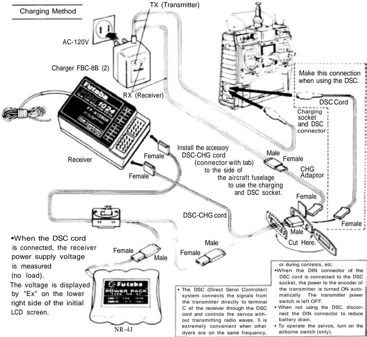
BATTERY CHARGING INSTRUCTIONS
(Transmitter and Receiver Nicd Batteries)
Before operating your system, recharge the Nicd batteries as follows:
- Connect the DIN connector of the FBC-8B (2) battery charger to the transmitter charging socket, and connect the 3P connector to the airborne NR-4J Nicd battery pack and plug the battery charger into a 120VAC outlet as shown in the figure.
- The TX and RX LEDs light to show that batteries are being charged. The Nicd batteries can also be charged through the DSC-CHG cord by connecting the CHG adaptor to the charger as shown in the figure. This allows the NR-4J airborne Nicd pack to be charged without removing it from the model.
- Normally recharge the battery for about 15 hours. If it has not been used for some time, discharge and recharge it two or three times,
then charge it a full 15 hours.
- The amount of time remaining before the batteries must be recharged can be estimated by checking the integrated timer at the moment the TX battery alarm sounds (antenna extended).
- Leaving batteries in the discharged state for a long time will adversely affect their capacity and life.
- The TX and RX Nicd batteries can be charged simultaneously or independently.
- A fully-charged TX battery can be used for about 10 flights of 10 minutes each. The airborne NR-4J Nicd battery pack can be used for about 7 flights when 6 servos are used and about 4 flights when 10 servos are used.
- BASIC TRANSMITTER T9VAP CONTROLS.
Refer to the fold-out illustration in the back of the manual.
- Aileron
- Elevator
- Throttle
- Rudder
- Landing Gear Switch
- Flap and Trim Control (CH6) Knob
- Spoiler (CH7) Knob Controls the spoilers as CH7.
- Pitch Control (CH8) Lever Serves as Pitch Control High Side Trimmer in THR->PIT mixing
- Idle-Up Lever Sets engine idling speed during THR PIT mixing
- Flap Spoiler Elevator mixing switch
Upper Position: Elevator Flap mixing
Center Position: OFF
Lower Position: Flap -> Elevator mixing Spoiler
- Snap RollON/OFF Switch
Snap function operates when pulled forward. Switch is spring-loaded and snap function turns OFF when released. - Aileron Dual Rate Switch
- Elevator Dual Rate Switch
- Rudder Dual Rate/CHS Switch
- Programmable Mixing ON/OFF Switch
- Throttle -> Pitch Control Mixing ON/OFF Switch
Non-slip Adjustable Control Sticks
The length of the control sticks can be adjusted to suit operator preference.
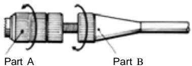
Unlock Parts A and B by turning them in opposite directions as indicated by the arrows, and adjust the control stick to the most comfortable length.
Adjustable Stick Angle
The horizontal angle of the control sticks can be
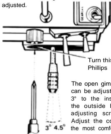
Phillips
Screwdriver
Turn this screw with a Phillips screwdriver.
The open gimbal stick angle can be adjusted from about 3^ to the inside to 4.5^ to the outside by turning the adjusting screw as shown. Adjust the control stick to the most comfortable angle.
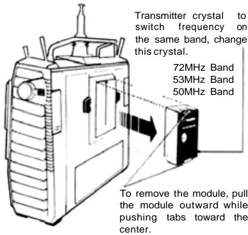
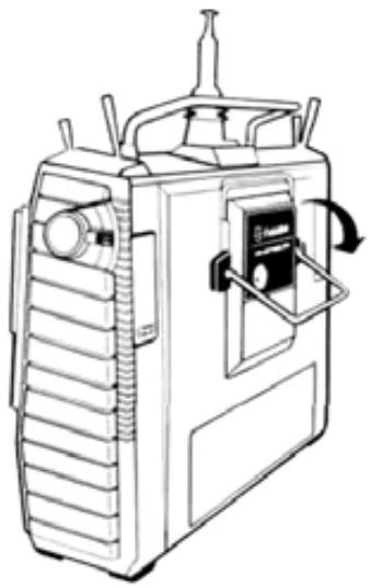
Transmitter RF Module
A temperature rise in the RF module during use is normal.
Mini Stand
Use this fold-out Mini Stand as shown when laying the transmitter down. This makes operation easier and protects the transmitter and module.
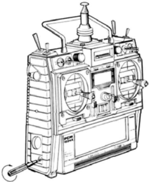
Transmitter Battery Pack Replacement
Remove the battery box cover. Lift out the Nicd battery pack and disconnect the connector.
NOTE: Be careful not to drop the Nicd battery pack.
Opening Trimmer Panel and Key Cover
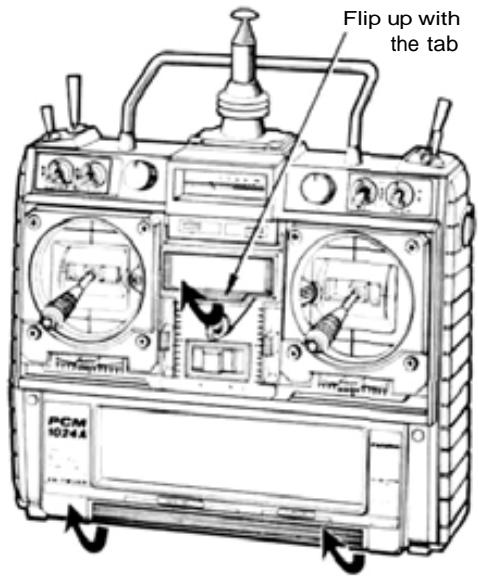
NOTE: Flip up at both sides with your fingers. Do not try to open the panel at the center. The cover may be damaged.
Screen contrast adjustment
Adjust the screen contrast with the special screwdriver provided. The contrast increases when the adjusting screw is turned clockwise.
Monitor Lamps
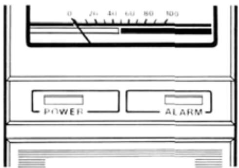
The POWER Lamp lights when the transmitter power is turned ON.
The ALARM LED Lamp at the right:
- Blinks off once per minute during Fail Safe data transmission.
- Blinks on and off when an activated mixing switch is ON (Snap roll. Air brake)
- Lights steadily at all other times.
Functions of Sub-Trimmers
Sub-trimmers are located on the front panel to allow convenient trimming of programmed settings on the field or during flight. Master the computer functions before using them.
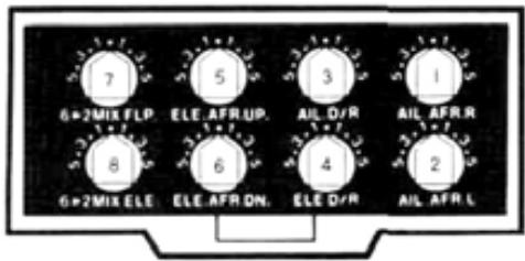
- AIL.AFR.R Aileron right endpoint adjustment.
- AIL.AFR.L Aileron left endpoint adjustment.
- AIL.D/R Aileron Dual Rate throw adjustment
(This trimmer is ineffective if AIL D/R is not set to ACT)
See D/R instructions page
- ELE.D/R Elevator Dual Rate throw adjustment
(This trimmer is ineffective if ELV D/R is not set to ACT)
See D/R instructions page - ELE.AFR.UP Elevator up endpoint adjustment.
- ELE.AFR.DN Elevator down endpoint adjustment.
- 6->2MIX FLP. Airbrake Mixing Flap adjustment.
- 6->2MIX ELE. Airbrake Mixing Elevator adjustment.
(Trimmer No. 7 and 8 are ineffective if the Airbrake Mixing program is not set to ACT). See page
OPERATING INSTRUCTIONS.
- When adjusting and setting the transmitter functions, connect the receiver and servos, and make the adjustments while observing the operation of the servos.
- Alternatively, when studying the operation of transmitter functions, remove the transmitter RF module (to reduce battery drain). The effects of adjustments can be viewed on the SRV program screen (See page 48).
- Set the power switch to the ON position. The standard screen shown below appears on the LCD display.
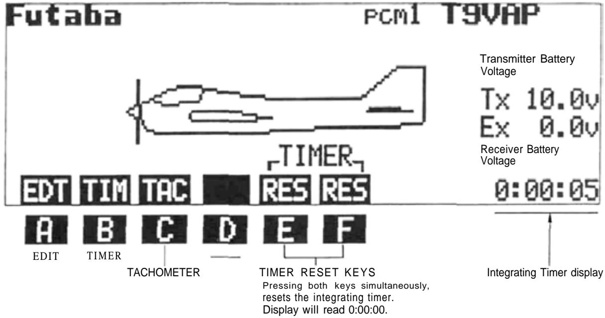
-Tx 10.1V Transmitter Voltage
- Ex 0.0V The receiver battery voltage can be measured by using the DSC cord supplied.

TIMER
The TIMER function can be used to monitor flying time, fuel consumption, at contests, etc. Four different timing functions are available: Up Timer, Down Timer, Rhythmic Timer, and Total (Integrating) Timer.
Timer Functions
1) Up Timer This timer counts up from zero in 1 second steps. Its maximum count is 59:59. When the alarm time is set, a buzzer begins to sound 10 seconds before the set time is up. The buzzer also sounds at each 1 minute interval. When the time reaches 59:59, timing restarts from 00:00.
2) Down Timer This timer counts down from the set time in 1 second steps. Operation is otherwise the same as the Up Timer.
3) Rhythmic Timer This is a 0.1 second cyclic timer. A buzzer sounds at each set alarm interval. When the set alarm interval elapses, the counting automatically restarts.
4) Total (Integrating) Timer This timer records the total transmitter ON time. It is very useful for estimating remaining Nicd battery capacity and monitoring total flying time. Maximum count is 59:59:59.
Setting Instructions
1) Display the standard screen.
2)ResettheTotalTimerbypressingthetwoprogramkeyssimultaneously.RES
3) Press the TIM key. The TIMER program screen will appear on the display. The Up Timer will be displayed first.
4) Select the UP (Up), DN (Down), or RYT (Rhythmic) timer mode by pressing the UP, DN, or RYT program key. The example shown is for the Up Timer.
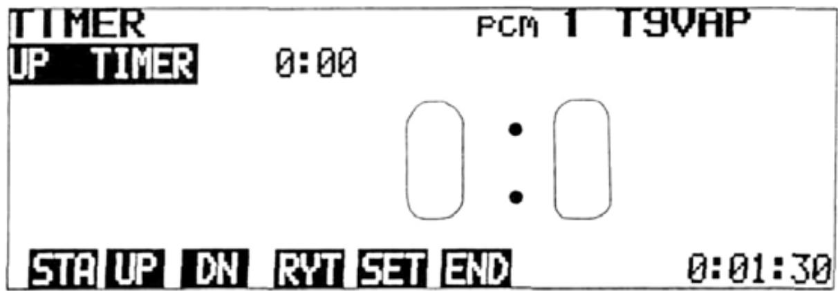
5) To set the-alarm time, switch to the TIMER SET display by pressing the SET key. Move the cursor to the timer mode to be set using the , , . and cursor keys. Pressing the RES key will
Set the alarm time with the + and - program keys.

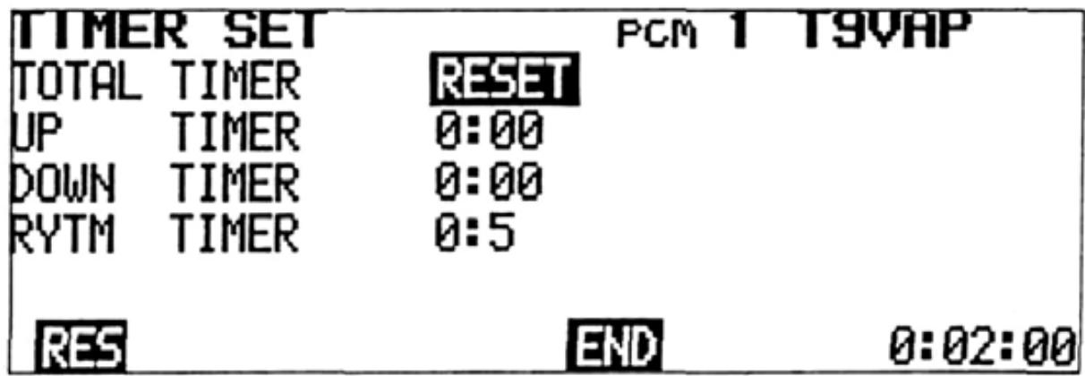
When time and alarm setting is complete, return to the TIMER display by pressing the END program key.
6) To start the timer, press the STA program key. The program key characters STA change to STP 7). When the STP key is pressed, the timer stops.
7) When the END program key is pressed, the display returns to the standard screen.
Timer Counting Range 1. UP/DN Timers 55min.59sec.
- Total Timer 55 hrs. 59 min. 59 sec.
- Rhythmic Timer 0.5 sec. to 59.9 sec. interval
ADJUSTMENTS AND FLIGHT TECHNIQUES

TACHOMETER Tachometer
The tachometer function is used to measure the speed on one to five-bladed propellers, etc. Speed (rpm) is measured up to a maximum of 50,000 rpm (in 20 rpm increments).
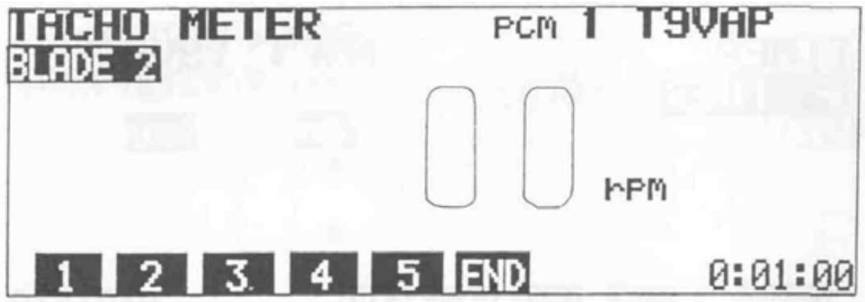
Setting Method
1) Display the standard screen, and press the TAC program key.
2) Press program key 1 to 5 to select the number of blades. Ex: 2 for a two-bladed propeller.
3) Measure the speed by pointing the built-in sensor on the transmitter (center of the left
side panel) at the front or rear of the propeller disc from a distance of 8 to 12 inches. Be sure the model is restrained by an assistant, and be very careful of the rotating propeller.
Allow a few seconds for the display to stabilize, then read the measured value. Maximum speed range is 50,000 rpm.
Low Battery Warning
Low Battery Warning
This function operates when the transmitter Nicd battery voltage drops below 8.5 volts. The characters "LOW BATTERY" blink on the
screen, and a buzzer sounds. When this occurs, land immediately and recharge or replace the Nicd battery pack.
Back Up Warning
Back Up Warning
When the stored data is lost, the characters "BACK UP" blink on the screen and a buzzer sounds. When the power switch is turned on again, the error display disappears and all the settings return to the factory-set values. When
a Back Up error occurs, the back-up lithium battery is probably dead, or there is trouble in the system. To locate the cause, call your Futaba service center. The back up lithium battery life depends on the usage state, but is about 5 years.
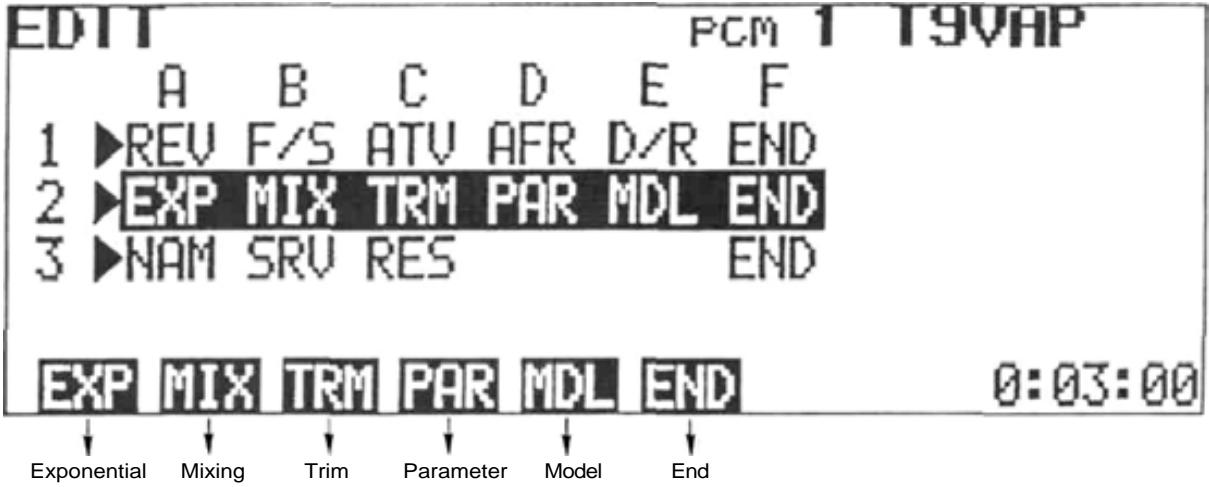
1>REV F/S ATV AFR D/R END
SYSTEM PROGRAMMING
Press the EDIT program key [EDT] of the standard screen.
Pressing the EDT (EDIT) program key of the standard screen will display the EDIT or "Menu" screen. The and cursor keys can be used to move the cursor bar to Line 1, 2, or 3 of the screen. The program keys are used to select the desired programming screen to be displayed.
NOTE: At all times, pressing the END program key will return the display to the next previous screen. To return to the standard screen, just keep pressing the END key.
ADJUSTMENTS AND FLIGHT TECHNIQUES
REVERSE Servo Reversing
This function is used to change the direction of servo operation in relation to control stick or lever movement.
Setting Method
1) Select the EDIT screen, the select the REVERSE screen by pressing the REV program key.
2) Select the desired channel with the <- and -> cursor keys.
3) Select NORMAL or REVERSE operation by
pressing the NOR or REV program key. In the display example, RUD (Rudder) is set to REVERSE.
4) Return to the EDIT screen by pressing the END program key.

FAIL SAFE Fail Safe
Fail Safe and Hold Functions
The HOLD (Hold) and F/S (Failsafe) functions are designed to allow the aircraft to "fly through" a momentary loss of signal or very strong interference, rather than experiencing the familiar "glitch" as the servos react violently to the unwanted signal. These functions cannot be expected to prevent a crash however, if the normal signal interruption is of sufficient duration.
The HOLD function stops the servo at the position held just before the normal signal is lost. When a normal signal is again received, the Hold function is released.
The FAILSAFE function will move a servo to a pre-set position when the normal signal is interrupted for 1 second or longer (The system will remain in HOLD for the first 1 second of signal loss). When a normal signal resumes, FAILSAFE is released.
BFS (Battery Fail Safe) Function
The BFS function moves the throttle (CH3) servo to the pre-set Fail Safe position when the airborne power supply is nearly exhausted. If no Fail Safe position has been set, the throttle servo will move to medium slow (neutral).
BFS can be released by lowering the throttle stick past the release point (adjustable), or with the CH9 switch. Throttle control is then regained for about 30 seconds. At the end of 30 seconds, BFS will re-engage and the throttle will again move to the Fail Safe position. Whenever BFS engages, land the aircraft as quickly as possible and recharge or replace the Nicd battery pack.
Fail Safe and Hold General Instructions
Fail Safe
F/S or HOLD can be selected for each channel (1 to 8).
- Channels selected for HOLD will remain in HOLD until a normal signal resumes. Those selected for F/S will move to their pre-set positions after 1 second of signal interruption.
- F/S SET simultaneously stores the desired Fail Safe position in the transmitter memory and sends it to the receiver.
- The F/S data is automatically sent to the receiver when the transmitter is first turned ON and at one minute intervals as long as the transmitter is left on.
- The F/S position can be checked with the CHK programkey.
- Only the Throttle channel (CH3) can be set for Battery Fail Safe.
Fail Safe Setting
1) Display the EDIT screen, then select the FAILSAFE screen by pressing the F/S program key.
2) Move the cursor to the desired channel with the and cursor keys and select HOLD or F/S for each channel by pressing the HLO or F/S program key. When Failsafe is selected, the number 50 will appear below the appropriate channel on the POSI- (%) line of the FAILSAFE screen.
3) Store the Failsafe positions in the transmitter memory by pressing the SET key while holding the stick or lever of the channel being set in the desired Failsafe position. Simultaneously, the data is also transmitted to the receiver and is automatically re-transmitted at one minute intervals.
Battery Fail Safe Setting
1) Set the Failsafe position on the throttle channel (CH3) as described above. A position slightly above the minimum engine idle speed is recommended.
2) BFS Release Point Setting (When THR is designated as the release channel)
- Move the cursor to the B/FS-RESET line of the FAILSAFE screen with the cursor key.
- Select the BFS release channel with the THR or 9CH program key.
- Set the throttle stick to the desired BFS release point and press the THR program key. This designates CH3 (Throttle) as the release channel and sets the stick release point simultaneously.
3) To release BFS by the CH9 switch, press the SCH program key.
- BFS can be released by the CH9 switch only when the switch is moved to the upper position. If the CH9 switch is in the lower position, BFS cannot be released.
- In the BFS release state, the characters 0% -RESET are displayed on the B/FS-RESET line of the FAILSAFE screen.
4) If Battery Fail Safe is not desired, press the INH program key (when the cursor is on the B/FS-RESET line). The BFS function will then be disabled.
In the example below, THR (Throttle) was set to Fail Safe and Battery Fail Safe.
ADJUSTMENTS AND FLIGHT TECHNIQUES

ADJUSTABLE TRAVEL VOLUME
- The ATV function is used to adjust servo travel limits. Servo travel can be adjusted independently in each direction from neutral. Adjustment from 30% to 110% of normal full travel (throw) is possible.
- NOTE: When servo travel is changed by ATV, the limits of trim throw and the Dual Rate ON (Low Rate) limits are increased or reduced by the same percentage.
- ATV limits are displayed by a bar graph and numbers. The point at which the cursor moves from left to right, as the stick or lever is moved, is the electrical neutral point of that channel.
Setting Method
1) Select the EDIT screen, then select the ATV program screen by pressing the ATV program key.
2) Rate data (endpoint limits) for Channels 1 to 4 is displayed on the screen. To display and adjust Channels 5 to 8, press the 5-8 program key. Rate data for Channels 5 to 8 will be displayed.
3) Select the channel to be set with the and cursor keys.
4) Operate the control stick, lever, or switch of the channel to be adjusted to its maximum
extent in the desired direction. The cursor will automatically move to the left or right confirming the direction to be set.
5) Servo endpoint limits can be set by pressing the + and - program keys while holding the appropriate stick or lever in the same direction. Pressing the 100 program key will return the set limit to 100% .
6) When you are finished, press the END key to return to the EDIT screen.
In the example shown, the CH1 (Aileron) right throw is reduced to 90% .
In the bar graph illustration below, the right hand throw is reduced to 50% of normal, while the left hand throw is set to 100% . Note that on the right side. Dual Rate ON (Low Rate) and Trim throw limits are also reduced to 50% of normal.
AFR is a servo endpoint limiting function, similar to ATV with three exception:
- AFR limits only the Dual Rate OFF (High Rate) servo travel. Trim throw and Dual Rate ON (Low Rate) limits are unaffected (unless AFR is reduced below the D/R ON limit).
- AFR can be used with mixing functions to adjust more than one channel simultaneously. For example, let's assume that the Aileron Differential mixing program is activated, and that CH1 controls the right aileron and CH7 controls the left aileron. AFR can be used to adjust the aileron control response because the CH1 and CH7 servos will be affected simultaneously (Ex: Reducing the left aileron AFR will reduce the left hand servo (CH7) UP throw and the right hand servo (CH1) DOWN throwsimultaneously.).
With ATV, the CH1 servo and CH7 servo throws in the above example would have to be adjusted separately.
- AFR sub trimmers are available on the front trimmer panel for Aileron and Elevator AFR. These allow quicker field adjustments in con
trol response without the necessity of going through the usual programming steps. Adjustments can even be made during flight (by an assistant). Maximum adjustment available on the sub trimmers is ± 25% of the amount of travel set on the AFR program screen.
Setting Method
1) The setting method for AFR is the same as for ATV (See page 16).
2) Select the EDIT screen and press the AFR program key.
3) The percentage figures displayed on the extreme left and right sides of the screen (CH1 and CH2 only) show the total amount of travel actually set (The amount set with the program keys + or - the amount set with the AFR sub trimmers.)
4) When the sub trimmers are turned slowly, a tone will sound at the exact neutral position. With the sub trimmer in neutral, the total travel will equal that set with the program keys.
In the bar graph illustration below, the right hand throw is reduced to 70% of normal throw by AFR. Note that the Dual Rate ON (Low Rate) limit and Trim throw limits remain the same on both sides (Compare with the ATV illustration on page 16).
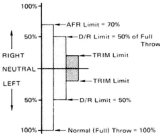
NOTE: Trim Limits and D/R Limits same in both directions.

DUAL RATE
Dual Rate functions allow the modeler to switch servo travel limits in flight, thus varying the control sensitivity for different flight conditions or maneuvers.
- Dual Rate functions are available on CH1 (Aileron), CH2 (Elevator), and CH4 (Rudder).
- Dual Rate ON (Low Rate) limits can be adjusted from 30% to 100% of full throw.
- If servo travel is reduced by ATV, the D/R ON throw will be 30% to 100% of the limit set by ATV (in D/R OFF). If AFR is used, the D/R ON limit is unaffected, and will be 30% to 110% of normal (full) throw.
- Dual Rate ON limits can be adjusted independently in each direction from neutral.
- There are three D/R ON/OFF Switches. Control of the three D/R functions can be assigned to these switches in any combination the modeler desires, or D/R functions can be switched ON and OFF automatically according to the position of the Throttle stick.
- The ON/OFF directions of the D/R Switches can be reversed using the PARAMETERS program screen (See page 43).
- In the AUTO D/R mode, the D/R functions can be turned ON and OFF according to the position (adjustable) of the throttle stick.
- The Trimmer Panel has D/R sub trimmers for CH1 (AIL) and CH2 (ELV). The D/R ON limits can be trimmed ± 25% of the amount set on the screen using these trimmers. The characters in ( ) on the far right side of the screen (CH1 and CH2 only) indicate the actual set amount (the amount set with the program keys ± the sub trimmer setting).
Setting Method
1) Select the EDIT screen, then select the DUAL RATE screen with the D/R program key.
2) Select the channel to be set with the or cursor key.
3) Move the cursor to the INH position with the
or cursor key and press the INH or ACT program key to activate or deactivate the D/R function for that channel.
4) When the ACT key is pressed, "ON" or "OFF" will be displayed in the "INH" position, depending upon the position of the pertinent D/R ON/OFF switch.
5) Using the and cursor keys, move the cursor to the L/D or R/U position and set the desired D/R ON throw with the + or program keys. Pressing the 100 program key will return the set limit to 100% . 100% .
6) Select the desired ON/OFF Switch for each D/R function by moving the cursor to the "sw" position with the or key and selecting switch No. 1, 2, or 3 with the 1 2 ,or 3 program key.
The D/R ON/OFF Switches are designated by numbers as follows:
1 ... Aileron D/R
As designated on the
2 ... Elevator D/R
transmitter front.
3... Rudder D/R
Each switch may be used to control one, two, or all three D/R functions as desired.
7) Field adjustment of the D/R ON limits is convenient using the AIL and ELE. D/R sub trimmers on the trimmer panel. The adjustment range is ± 25% of the amount set with the program keys. A tone will sound at the neutral (sub trim amount = 0 ) position of each sub trimmer.
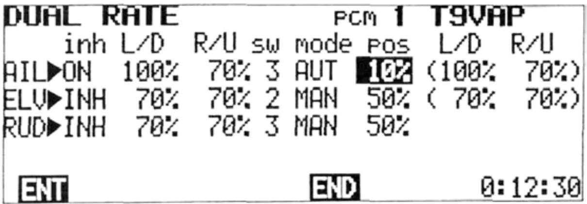
Auto Dual Rate
- Dual Rate functions may be switched ON and OFF automatically, according to the Throttle (CH3) control stick position.
1) Move the cursor to the "mode" position with the or cursor key.
2) Use the or cursor key to select the D/R function to be set to AUTO and press the AUT program key.
3) Use the and cursor keys-to move the cursor to "pos".
4) Set the Throttle stick at the point you wish ON/OFF switching to occur, and press the ENT program key.
5) When the Throttle stick is below the ON/OFF switching point and the pertinent D/R ON/ OFF Switch is set to OFF, Dual Rate will be OFF.
- If the assigned D/R ON/OFF Switch is set to ON, then D/R will be ON even if the Throttle stick is still below the ON/OFF point.
6) When the Throttle stick is moved above the ON/OFF point, then D/R will be ON, regardless of the position of the D/R ON/OFF Switch.
NOTE: Dual Rate ON/OFF Switch directions can be reversed using the PARAMETER program screen (See D/R SW DIR page 43).
In the example shown, the AIL Dual Rate function will be switched to D/R ON (Low Rate) when the Throttle stick is moved above the 10% position. AIL and RUD D/R functions are both set to switch No. 3.

End Soft Key
Press the END program key to return to the EDIT screen.
ADJUSTMENTS AND FLIGHT TECHNIQUES
2EXP MIX TRM PAR MDL END
Select the EDIT screen, and move the cursor to Line 2 with the or t cursor key.

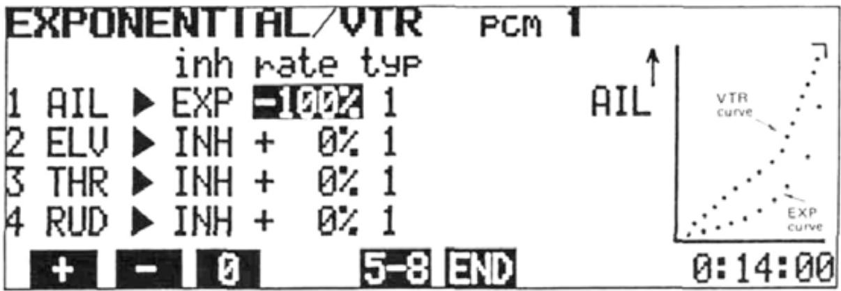
EXPONENTIAL/VTR
Exponential or VTR functions can be used to change the servo response curve from the normal linear operation. This can be very helpful if control response is either sluggish or too sensitive near the neutral position. Maximum servo deflection limits (set by ATV and/or AFR) remain the same.
Exponential
- With Exponential control, the amount of servo movement in relation to a given amount of control stick deflection can be made to steadily increase (or decrease) as the stick is moved farther from neutral (or as in the case of CH3 (Throttle), from one extreme to the other).
- Exponential control is available on CH1 to CH8.
- Two different types of Exponential response curves can be selected. The TYPE 1 Curve is symmetrical in both directions from neutral. This type is generally
used, when desired, on "neutralizing" controls such as AIL, ELEV. and RUD.
The TYPE 2 Curve is exponential in one direction over the full stroke of the control stick or lever. This type is normally used with functions such as THR.
- The amount of exponential can be varied from 0% to 100% in 4% steps. By using positive or negative exponential with either the TYPE 1 or TYPE 2 EXPO Curves, a total of four different types of Exponential control response can be selected.
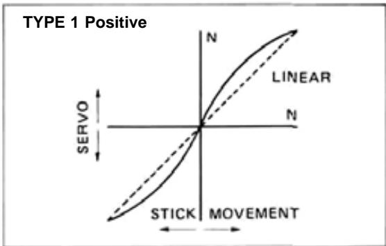
With this type of curve, control response will be made more sensitive near neutral and less sensitive as the stick is deflected farther towards its extreme limits.
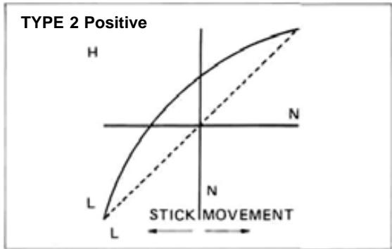
With this type of curve, response will be most sensitive at the LOW end of control stick travel, and decrease as the stick is moved toward HIGH.
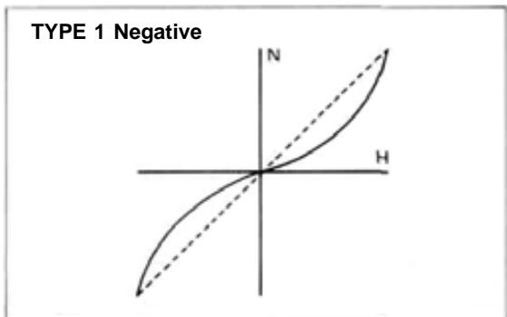
With this type of curve, control response wilt be "softer" around neutral and increase as the stick is deflected farther.
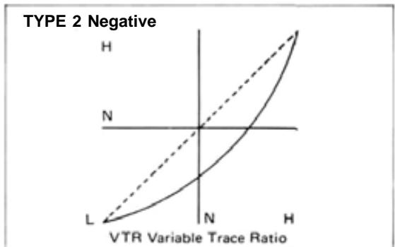
With this curve, the response is less at the LOW end and steadily increases as the stick is moved toward HIGH.
- When VTR is used, servo response remains linear, but the response is automatically switched to a higher rate at a certain (adjustable) point in the control stick deflection.
- The initial response rate is the same as the Dual Rate ON rate (See page 18).
Maximum servo travel limit is still controlled by ATV and/or AFR.
Setting Methods
Exponential
1) Select the EDIT screen and move the cursor to Line 2 with the + cursorkey.or Select the EXPONENTIAL/VTR program screen by pressing the EXP program key.
2) Select the channel to be set with the or cursor key, then select the operation mode with the INH, EXP VTR program, or key. VTR is available only on CH1, CH2, and CH4.
3) When the EXP mode is selected, the type of curve can be selected by moving the cursor to the "typ" position with the or cursor key and pressing the 1 or 2 program key. (The type of curve is not selected in the VTR mode.)
4) When the EXP or VTR mode is selected, the servo response curve is displayed on a graph at the right side of the screen. The amount of Expo can be changed by moving the cursor to
the "rate" position and pressing the + or - program key. When the 0 program key is pressed, the rate is preset to 0% ( 0% = normal or linear).
5) In the VTR mode, the "rate" adjustment is used to adjust the stick position at which the servo response changes from Low to High. The initial (Low) rate is adjusted by the D/R adjustment program (See page 18).
6) Channels 5 through 8 can be displayed and set by pressing the 5-8 program key.
In the above example, a TYPE 2 Negative Exponential Curve is shown. This type is often helpful on the Throttle channel. Depending on the carburetor design and linkage, actual power transition can be made more linear in relation to stick movement. (About -20% is a good initial setting for fixed-wing aircraft).
ADJUSTMENTS AND FLIGHT TECHNIQUES

MIXING
- Mixing allows two or more channels to be controlled by a single transmitter control stick or lever. This set features Programmable Mixing with four independent mixing circuits, along with special built-in mixing circuits.
- NOTE: Only PROG-MIX Programmable Mixing can be used in the BASIC Parameter mode. (See PARAMETER, page 43).
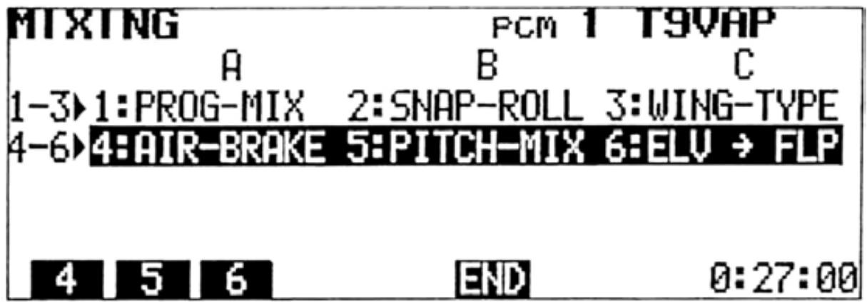
There are six types of mixing (including Prog. Mixing).
1: PROG-MIX
Programmable Mixing
2: SNAP-ROLL
Snap Roll
3: WING-TYPE
Wing Type (Mutual Mixing)
4: AIR-BRAKE
6,7->2MIX
5: PITCH-MIX
3->8MIX
6:ELV->FLP
Elevator Flap Mixing
2->6MIX
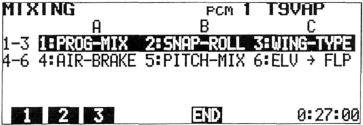
Setting Method
1) Select the EDIT screen and move the cursor to Line 2 with the cursor key, then press the [MIX program key.
2) to 6 can be selected with the program keys.
3) To use 1:PROG-MIX, press the 1 program key. The PROGRAMABLE MIX screen will be displayed.
1:PROG-MIX
PROGRAMABLE MIX Programmable Mixing
Four separate Programmable Mixing circuits allow almost infinite mixing combinations. The features of this program provide the modeler with unlimited versatility in trimming and controlling complex, high-performance models.
- Mixing of any two channels is possible.
- Four completely independent mixing circuits are available.
- Mixing amounts can be adjusted independently in either direction from neutral or offset point.
- The PROG-MIX ON/OFF Switch can be selected.
- The point at which the mixing direction reverses is fully-adjustable.
- PROG-MIX circuits can be mixed with or "slaved" to built-in mixing functions.
PROG-MIX circuits can be mixed with each other. - Trim corrections on the "Master" channel can be added to the slave channel or not, as desired.
- Bi-directional mixing can be accomplished using two mixing circuits (Ex: Flapperons)
- Adverse coupling of control inputs in fixed-wing aircraft can be eliminated. (Ex: Tendency to roll when rudder is applied in knife-edge flight.)
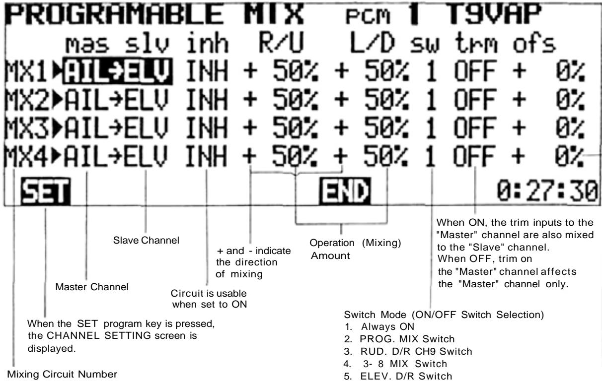
Indicates the control stick position
that the mixing reference
point (R/L or U/D Direction Change Point) is offset to.
CHANNEL SETTING
Master and Slave Channel Selection
In the first example shown, THR (Throttle) is set at "mas". The Master channel can be changed by pressing the + - programkey.or
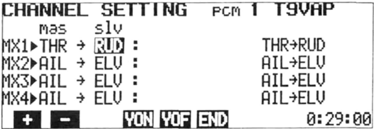
The cursor can be moved to the "slv" position with the or cursor key and the Slave channel selected by pressing the + or - program key.
Master Channel Setting
1) Select the PROG-MIX screen as described on page 22.
2) Select the CHANNEL SETTING screen by pressing the SET program key.
3) The Master channel can be set by pressing the + or - program key to change the channel.
4) The mixing circuit to be programmed can be selected by moving the cursor with the or cursor key.
Slave Channel Setting
1) Move the cursor to the "slv" position with the or cursor key.
2) Select the Slave channel with the + or - program key. In the example above, the Slave channel on MX1 (Mixing Circuit No. 1) is set to AIL.
Combination of Mixing Circuits
Programmable mixing circuits can be combined with each other, or with built-in mixing circuits by two methods.
1) Setting a Mixing Circuit No. in the "mas" position (MX1, MX2, MX3, or MX4).
2) XON and XON setting.
XON and YON Method
D XON XOF are displayed when the cursor is in the "mas" position. YON YOF are displayed when the cursor is in the "slv" position.
- XON display
- YON display
- Displayed when cursor is in "mas" position. Indicates that Master channel is "slaved" to another circuit.
Mixing Number Method
Depending upon which channels are selected on different mixing circuits, MX1, MX2, MX3, or MX4 can be displayed in the "mas" position. The slave channel of the mixing number displayed in the "mas" column, then becomes a Master channel on the mixing circuit line that it is displayed and the two circuits are connected.
2) To activate XON or YON mixing, press the XON or YON key. The character will appear next to the appropriate channel on the left side of the screen to indicate that XON or YON has been set.
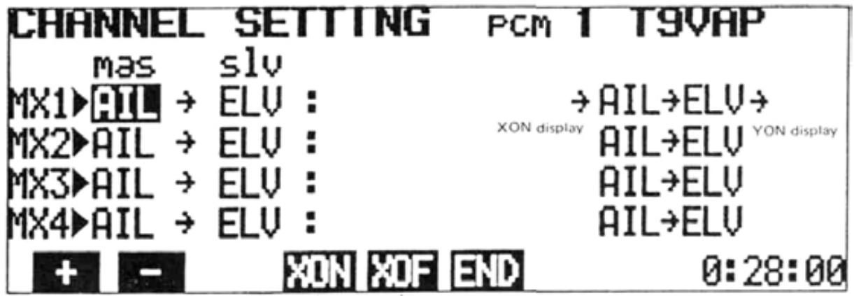
Displayed YON YOF for slave channel
ADJUSTMENTS AND FLIGHT TECHNIQUES
- Combinations allow more efficient use of the number of mixing circuits. An example is shown below.
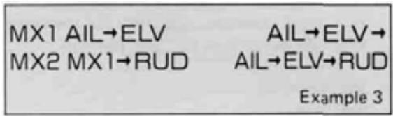
When XON and YON are not used, three circuits are required for the mixing program shown below. Programmable mixing is performed from Aileron to Elevator and Rudder, and from Elevator to Rudder. This is the same as AIL -> ELV -> RUD mixing.
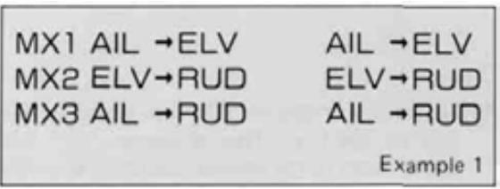
The same mixing program as in Example 1 can be set up using only two 2 mixing circuits when the XON and YON functions are used.
MX1 is set to AIL -> ELV mixing.
MX2 is set to ELV -> RUD mixing.
The cursor is moved to the MX1 "slv" position,
and YON is set. The cursor is then moved to the "mas" position and XON is set. MX3 is turned OFF (Set to INH). This is also the equivalent of AIL -> ELV -> RUD mixing.
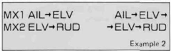
Setting MX1 as the MX2 Master channel in the example is the same as setting XON.
- Combinations are effective when the number of mixing circuits is insufficient, and when PROG-MIX circuits are mixed with built-in mixing circuits.
- Activation of Programmable Mixing Circuits
1) Move the cursor to the 'INH" position with the + or cursor key.
2) To activate the circuit, press the ACT key. "ON" or "OFF" will be displayed according to the position of the designated Mixing ON/OFF switch.
3) To deactivate the mixing circuit, press the INH program key.
- Mixing Rate and Direction Setting
The mixing rate setting determines the amount of deflection of the Slave servo in relation to movement of the Master channel control stick or lever. Both the amount (rate) and direction (+ or -) of movement can be set independently, either side of the mixing point (neutral).
1) Move the cursor to the R/U or L/D position with the or cursor key.
2) Set the desired rate with the + , - , or 100 program key.
3) The servo operating direction can be changed with the + and - program keys.
Mixing ON/OFF Switch Selection
Programmable Mixing can be designated as "always ON" or switched ON and OFF in flight by any four different switches.
1) Move the cursor to the "sw" position with the or cursor key.
2) Press the appropriate program key (1 through 5) for the switch selection desired.
Switch assignments are designated by numbers as shown below:
| 1. | Always ON |
| 2. | PROG. MIX Switch |
| 3. | RUD. D/R/CH9 Switch |
| 4. | 3--8 MIX Switch |
| 5. | ELEV. D/R Switch |
Trim ON/OFF Setting
-
In the "Trim ON" mode, trim lever inputs on the Master channel will be "carried over" to the Slave channel, causing a corresponding change in the Slave channel neutral position when the mixing is ON. In the "Trim OFF" mode, trim changes to the Master channel affect the master channel only, regardless of the mixing ON/OFF switch position.
-
Trim ON/OFF selection is only relevant if the Master is a primary control stick (AIL, ELEV, RUD, AND THR).
Setting Method
1) Move the cursor to the "trm" position with the or cursor key.
2) Select the "Trim ON" or "Trim OFF" mode with the ON or OFF program key.
OffsetRate and Direction Change Point)Setting
- Normally, the neutral (center) position of the Master channel control stick will be the point at which the Slave channel servo rate and direction change occurs. This control stick position can be changed (Offset) if desired.
1) Move the cursor to the "ofs" position with the or cursor key.
2) Move the Master channel control stick to the desired position at which you wish rate and direction change of the Slave channel servo to occur. (Mixing amount = 0 Point)
3) Press the ENT key. The Master channel stick position is memorized and will be displayed as a percentage in the "ofs" position of the screen. "+" indicates a stick position to the R/U side of neutral. "-" indicates a position to the L/D side of neutral. "0%" indicates that the direction will change at the normal control stick neutral position.
EXAMPLES OF PROGRAMABLE MIXING
Programmable Mixing combinations are extremely versatile and can be as complex as desired, limited only by the modeler's needs and imagination. A few/examples of how mixing functions can be used are shown below:
- Eliminating Unwanted Control Interactions
Adverse control interactions (caused by trim, model inaccuracies, etc.) can be compensated for automatically, with the use of the Programmable Mixing function.
As an example, let's presume that when top rudder is applied during "knife-edge" flight, an unwanted movement toward the top of the aircraft occurs. We can use a Programmable Mixing circuit to automatically apply a small amount of DOWN Elevator control with the application of top (Right or Left!) Rudder.
Setting Method
1) Select the PROGRAMABLE MIX screen and press the SET key to display the CHANNEL SETTING screen.
2) Select RUD as the Master "mas" channel on MX1 circuit using the + or - program key.
3) Move the cursor to the "slv" position and select ELV as the Slave channel. RUD -> ELV will appear on the right side of the screen.
4) Return to the PROGRAMABLE MIX screen by pressing the END key.
5) Move the cursor to the "inn" position and press the ACT key.
6) Move the cursor to the R/U and L/D positions. The direction of Elevator movement is set with the + and - program keys, and the rate (amount) of movement set with + and - program keys. Set the rate and direction to give a small amount of DOWN Elevator with the application of either direction of Rudder.
7) Move the cursor to the "sw" position and select the desired Mixing ON/OFF Switch option.
ADJUSTMENTS AND FLIGHT TECHNIQUES
F3A Pattern Aircraft
The figures below show multiple mixing functions in an F3A contest aircraft. Both built-in and Programmable mixing functions are used. Elevator Flap (CH6) mixing and Aileron Differential (CH1 and CH7) are used. In addition, the PROG-MIX function is used to allow the ailerons (CH1 and CH7) to act as flaps (flapperons) when ELV -> FLP mixing is ON.
Setting Method
1) Elevator flap Mixing (Built-in)
Press the ACT program key.
See Elevator Flap Mixing, paqe
2) Aileron Differential Mixing (Built-in)
Press the ACT program key.
See Aileron Differential Mixing, page
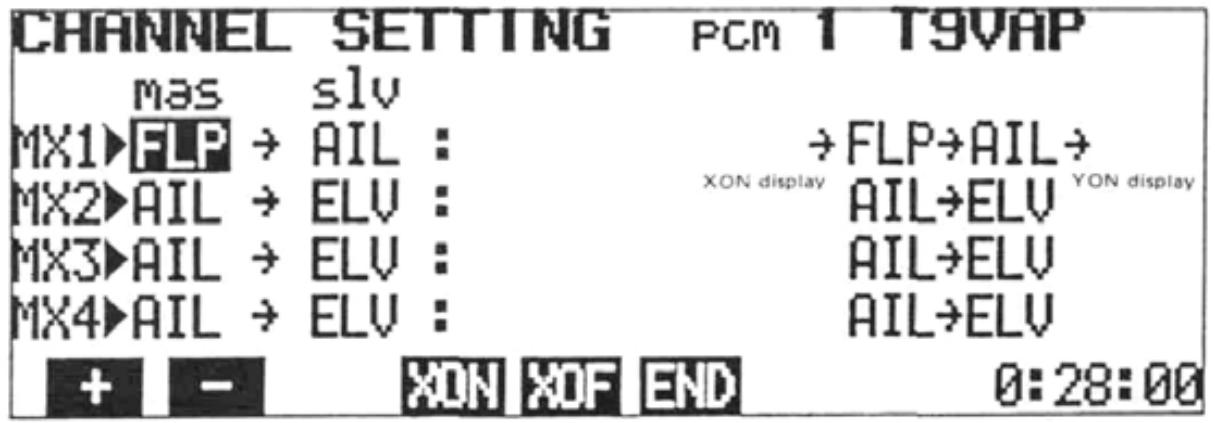
3) Set PROG MIX
- Select the Programmable Mixing CHANNEL SETTING screen.
- Set the "mas" channel to FLP with the + or - program key.
- Press the XON program key. ("Slaves" the PROG MIX 1 circuit to the built-in ELV -> FLP circuit.)
- Move the cursor to the "slv" position with the cursor key and set the "slv" channel to AIL with the + -key.or
- Press the YON program key. ("Slaves" the built-in AIL DIFF circuit to the PROG MIX 1 circuit.)
All the mixing channels are now designated. The screen should appear as below.
- Return to the PROGRAMABLE MIXING screen by pressing the END program key.
- Move the cursor to the "inn" position and press the ACT key.
- Move the cursor to the "sw" position and select the ON/OFF switch option desired.
4) Rate (amount) of movement of the FLP (CH6) servo in relation to the Elevator control stick is set in the ELV -> FLP mixing screen (page 40).
5) Aileron differential is set with the AILERON DIFFERENTIAL screen (page 32).
6) UP and DOWN movement of the Ailerons (CH1 and CH7) in relation to Elevator stick movement will be influenced by the rate set for ELV -> FLP mixing and by the rate set at U/R and L/D on the PROGRAMABLE MIXING screen. If the U/R and L/D rates are set at 100%, then the UP and DOWN movement of the Ailerons (at ELV -> FLP MIX ON) will be the same as set in Step 4) above.
F3B R/C Gliders
- Variable Wing Camber (Flaps and Flapperons) and Glide Path Control ("Butterfly" or "CROW" Mixing)
- CH1 and CH6 are used for Aileron servos. CH7 is used for the inboard Flaps. (2 servos with Y harness or 1 servo with dual linkage.)
Setting Method
1) Select the PROGRAMABLE MIX screen and press the SET program key.
2) Set the Master and Slave channels up as shown (See page 25):
->FLP->SPO
THR->FLP->
THR->SPO
ELV->SPO
3) Return to the PROGRAMABLE MIX screen by pressing the END key.
4) Set the screen up initially as shown:
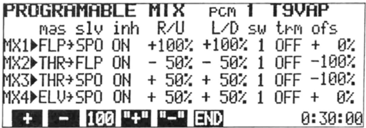
NOTE: Set Offset on MX2 and MX3 with the Throttle control stick at the full HIGH position.
5) Select the FLAPPERON screen and press the ACT program key. Move the cursor to the TRIM position and set the rate at 100% .
6) Return to the MIXING screen and move the cursor bar to the 2ND line. Press the program key to display the AIR-BRAKE screen.
7) Move the cursor to the ACT/INH position and press the ACT key.
8) Move the cursor to the FLP-TRIM position and set the trim rate to 100% .
- Right and left aileron servos (CH1 and CH6) operate to give normal aileron action when the aileron control stick is deflected.
-
The Flap (CH6) Knob can be used to raise or lower all four wing surfaces simultaneously to vary wing camber.
-
Moving the Throttle (CH3) stick from high to low will lower the flaps and raise the ailerons for Glide Path Control ("Butterfly" or "CROW") mixing.
- Moving the AIRBRAKE (6-7 -> 2 MIX) Switch to the ON position will lower all wing surfaces to a pre-set position. Slight DOWN camber is suggested for launching.
9) Change mixing and/or servo directions as necessary due to aircraft linkage, etc.
10) Adjust mixing rates, throws, etc. as desired. Be careful that combined throws are not excessive for the servo mechanics, linkage, etc.
11) Elevator -> Flap mixing can be used if desired (See page 40).
ADJUSTMENTS AND FLIGHT TECHNIQUES
2:SNAP-ROLL
SNAP ROLL
Snap rolls can be performed using the Snap Switch.
Four snap roll directions can be set: R / U (right up), R / D (right down), L / U (left up), and L / D (left down) snap. The snap roll direction is displayed on the screen. The throw of each servo (AIL, ELV, and RUD) is adjustable.
1. When the ENT (enter) key is pressed, the throw of each stick is set.
Setting Method
1) Select the EDIT screen and move the cursor to Line 2 with the cursor key, then press the MIX program key.
2) Press the 2 program key. The SNAP-ROLL screen will be displayed.
3) To activate the Snap Roll program, press the ACT PROGRAM KEY. To inactivate the Snap Roll, press the INH key.
4) Servo throw is set by pressing the ENT program key.
a) If the ENT key is pressed when the cursor is in the "ACT/INH" position, all rates will be set to the maximum AFR rate for each channel.
b) Rates can be set individually by moving the cursor to each rate position and using the + , - , or 100 program key. A good starting point is AIL - 110%, RUD - 50%, and ELV - 80%.
1. Snap roll not performed when LOCK. Snap roll performed when FREE.
5) Snap Roll direction can be selected during flight using the switches on the transmitter back.
6) AUTO Mode Setting:
a) Move the cursor to the MANUAL/AUTO position with the cursor key.
b) Set the retract Gear (CH5) Switch in the "gear down" position. Press the AUT program key. "AUTO" and "LOCK" will be displayed.
In the AUTO mode, the Snap Switch is inactivated when the landing gear is down (LOCK) and activated when the landing gear is retracted (FREE).
c) To return to the MANUAL mode, press the MAN program key.
NOTE: 1) After setting the AUTO mode, always check to be certain that Snap Roll is only active when the landing gear is UP.
2) SNAP ROLL mixing is not available in the BASIC mixing mode.
ADJUSTMENTS AND FLIGHT TECHNIQUES
3:ING-TYPE
WING TYPE
The WING TYPE program includes four built-in mixingcircuits.
- Aileron Differential
- Flapperons
- Elevon
- V-Tail
Servo directions and throws are fully-programmable.
Setting Method
Displaying the WING TYPE screen:
1) Select the EDIT screen and move the cursor to Line 2 with the cursor key, then press the MIX program key.
2) Press the 3 program key.
NOTE: WING TYPE mixing is not available in the BASIC mixing mode.
AIL DIFF
(Aileron Differential)
A differential between up and down movement of each aileron can be programmed. This is very helpful in correcting roll axis deviations. A separate servo must be used on each aileron. CH1 is used to control one aileron, and CH7 the opposing aileron.
1) Display the WING TYPE screen and press the program key.
2) To activate mixing, press the ACT program key and to deactivate the function, press the INH key.
to be set using the cursor keys. In the display example, the cursor was moved to the AIL (CH1) R/U position. (R/U represents the aileron right stick deflection and L/D represents the left stick deflection.)
4) Set the throw of the AIL (CH1) servo with the +, -, or 100 program key. To change the direction of operation of the servo, use the + programkey.or
5) Move the cursor to the AIL-2ND (CH7) servo line with the cursor key. Set the servo direction and throw as in Step 4).
6) Return to the WING TYPE screen by pressing the END program key.
NOTE: 1) When aileron differential is activated (ACT), the CH7 transmitter knob is deactivated and will not affect the CH7 servo position.
2) Flapperon and Elevon mixing cannot be used simultaneously with aileron differential. When AIL DIFF is activated, these programs are automatically deactivated.
FLAPPERON FLAPPERON
This mixing operation allows the ailerons to be raised and/or lowered simultaneously. Therefore acting as flaps. Normal aileron action is maintained as well. Individual aileron servos are required, one controlled by CH1 and the other by CH6.
Setting Method
1) Display the WING TYPE screen, and Dress the program key.
2) To activate mixing, press the ACT key. To deactivate, press the INH program key.
3) First set the throw and direction of the CH1 servo in response to aileron control stick deflection. Move the cursor to the AIL R/U
or L/D position with the cursoror key. (R/U represents right aileron stick deflection and L/D represents left stick deflection.) Servo throw is adjusted with the +, or 100 program key. Servo direction can be changed with the + program key.
When OFFSET is used. 0^ 45^ 60^ flaps can be used.
4) Set the throw of the AIL-2ND (CH6) servo by moving the cursor to the AIL-2ND line the or cursor key. Set the throw and direction in response to aileron stick movement as in Step 3).
5) Set the throw of the FLP-2ND (CH1) servo when the FLAP TRIM (CH6) Knob is turned by moving the cursor to the FLP-2ND line with the + cursorkey. Throwisor adjusted with the + , - , or 100 program key. Use the + or - key to change servo direction.
6) Set the throw of the FLP (CH6) servo when the FLAP TRIM (CH6) Knob is turned by moving the cursor to the FLP line with the or cursor key. Direction and rate (throw) are set as in Step 5).
7) The Flap Trim rate function can be used to adjust the throw of both servos simultaneously (in response to the CH6 Knob). The trim rate setting determines the maximum throw of the servos in response to the CH6 Knob. The throw set for FLP-2ND and FLP under R/U will be 0 to 100% of the maximum allowed by TRIM. Use the settings in Step 5) and 6) to correct small differences in throw between the two servos and TRIM to set the overall rate.
a) Move the cursor to the FLP line with the cursor key and to the TRIM position with the cursor key.
b) Set the throw with the +, -, or 100 program key.
8) The OFFSET function can be used to change the neutral position of the CH6 Knob. This can be used to allow more down throw than up throw. (for example)
a) Move the cursor to the FLP-2ND line with the cursor key. Then move the cursor to the OFFSET position with the key.
b) Set the CH6 Knob to the desired neutral position and press the ENT program key. The CH6 Knob position will be memorized and made the neutral position.
NOTE: If the TRIM rate is changed after entering the OFFSET position, the OFFSET will change and must be reset. Aileron mixing and elevon mixing cannot be used together with flapperon mixing. Therefore, when flapperon mixing is activated (ACT), AIL DIFF and ELEVON mixing are automatically deactivated (INH).
Elevon mixing can be used with delta wing aircraft, flying wings, tail-less aircraft, flying discs, etc. CH1 and CH2 are used as the operating channels.
Setting Method
1) Display the WING TYPE screen, then press the 3 program key.
2) To activate mixing, press the ACT key and to deactivate mixing, press the INH program key.
3) Set the throw of the AIL (CH1) servo when the aileron control stick is deflected by moving the cursor to the R/U or L/D position (R/U represents right aileron stick deflection and L/U represents left aileron stick deflection) with the or cursor key and pressing the +, - or 100 program key. Change servo operating directions with the + or - program key.
4) Set the throw of the AIL-2ND (CH2) servo when the aileron stick is deflected by moving the cursor to the AIL-2ND line with the or cursor key and setting throw as described in Step 3).
5) Set the throw of the ELV-2ND (CH1) servo when the elevator stick is moved by moving the cursor to the ELV-2ND line with the or cursor key and pressing the + , - , or 100 program key. Change the direction of operation with the + or - program key.
6) Set the throw of the ELV (CH2) servo when the elevator stick is deflected by moving the cursor to the ELV line with the or cursor key and setting the throw and direction as in Step 5).
7) Return to the original WING TYPE screen by pressing the END key.
NOTE: Elevon mixing cannot be used together with other WING TYPE mixing. Therefore, when ELEVON mixing is activated (ACT), all other WING TYPE mixing is deactivated (INH).
ADJUSTMENTS AND FLIGHT TECHNIQUES
V TRAIL
V-TAIL
V-Tail mixing is used for certain sailplanes, scale model Beechcraft Bonanzas, and other aircraft with V-Tails (Ruddervators). ELV (CH2) and RUD (CH4) are used as the operating channels.
Setting Method
1) Display the WING TYPE screen and press the program key.
2) To activate the V-Tail function, press the ACT program key. Press the INH key to deactivate mixing.
3) Set the throw of the ELV (CH2) servo when the elevator control stick is deflected by moving the cursor to the rate to be set with the or cursor key and using the + -, or 100 program key. If necessary, use the + or - program key to change the servo operating direction.
4) Set the throw of the ELV-2ND (CH4) servo when the elevator is deflected by moving the cursor to the ELV-2ND line with the or cursor key and setting the throw as described in Step 3).
5) Set the throw of the RUD-2ND (CH2) servo when the rudder control stick is deflected by moving the cursor to the RUD-2ND line with the or cursor key and setting the throw as in Step 3).
6) Set the throw of the RUD (CH4) servo when the rudder control stick is deflected by moving the cursor to the RUD line and setting the throw and direction as in Step 3).
7) Return to the original WING TYPE screen by pressing the END program key.
NOTE: V-Tail and ELEVON mixing cannot be used together. Therefore, when V-Tail is activated (ACT), Elevon mixing is automatically deactivated (INH).
Air-Brake is a pre-set, switch-activated mixing circuit that will deploy flaps (or flapperons), spoilers, and necessary elevator trim when the MIX switch is moved to the 6-7->2 position.
In the AUTO mode, the Air-Brake can be activated by lowering the throttle stick below a certain (adjustable) point.
Setting Method
1) Display the EDIT screen and move the cursor to Line 2 with the cursor key, then display the MIXING screen by pressing the MIX
program key. Move the cursor to the 4->6 line with the cursor key.
2) Press the 4 program key.
Note: AIR-BRAKE mixing cannot be used in the BASIC parameter mixing mode.
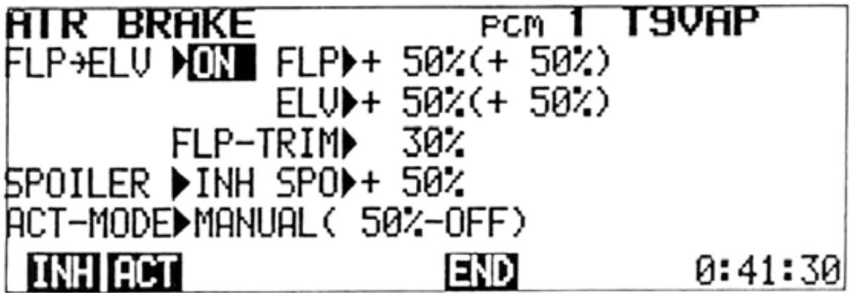
3) To activate the Air-Brake function, press the ACT program key. If the MIX switch is in the 6-7 -> 2 position, "ON" is displayed. If not, "OFF" is displayed. To deactivate mixing, press the INH key.
4) To activate the spoiler (CH7) servo, move the cursor to the INH position of the SPOILER line and press the ACT program key. When the Air-Brake is deployed, "ON" is displayed and when it is not operating, "OFF" is displayed. To deactivate the spoiler (CH7) servo, press the INH program key.
ADJUSTMENTS AND FLIGHT TECHNIQUES
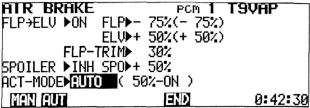
5) Set the servo throw at mixing by moving the cursor to the FLP, ELV, or SPO position with the cursor keys and setting the rate by pressing the + , - , or 100 program key. Use the + or - key to change the servo operating direction when necessary.
NOTE: The throw of the FLP and ELV servos can be conveniently changed by using the sub trimmers (6 -> 2MIX FLP. and 6 -> 2MIX ELE.). The characters in parentheses represent the rate actually set (computer value plus the sub-trimmer setting).
AUTO MODE SETTING
In the AUTO mode, the Air-Brake can be automatically deployed by lowering the throttle stick.
6) To set the AUTO mode, move the cursor to the ACT-MODE line with the or cursor key and press the AUT program key. The position of the throttle stick at that time is memorized as the mixing ON/OFF point. The Air-Brakewill deploy automatically when the throttle is moved below that point. To return to the manual mode, press the MAN program key.
7) To return to the original MIXING screen, press the END key.
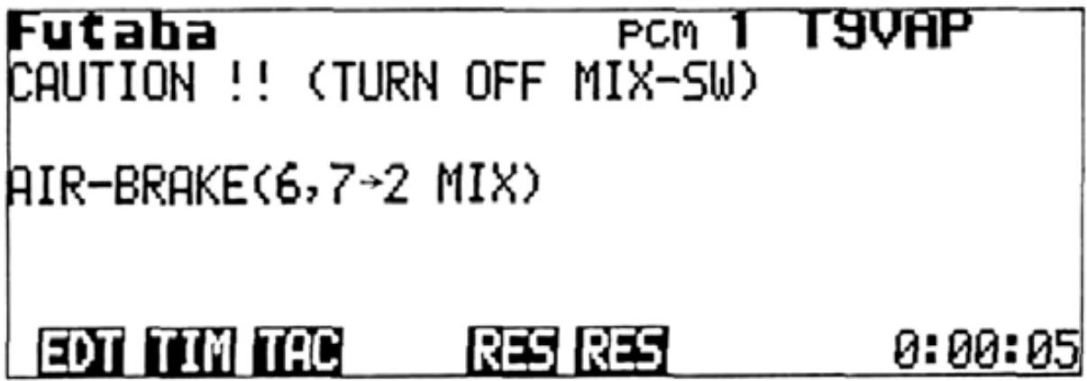
NOTE: If the AIR BRAKE Switch is inadvertently left ON when the transmitter power is turned OFF, a warning screen will be displayed when the power is again switched ON. A buzzer will also sound. When the AIR BRAKE switch is turned OFF, the normal initial screen will be displayed.
5:PITCH-MIX
PITCH CONTROL MIXING
Variable pitch propellers allow more constant speed aerobatics by providing an airbrake effect (reverse pitch) and the ability to adjust the high pitch from the transmitter. CH3 is used for throttle and CH8 for pitch control.
Setting Method
1) Select the EDIT screen and move the cursor to Line 2 with the cursor key, then display the MIXING screen by pressing the MIX program key. Move the cursor to the 2ND line with the cursor key.
2) Press the 5 program key.
To activate Throttle -> Pitch Mixing, press the ACT program key. If the 3 8 MIX Switch is ON at that time, "ON" is displayed. If the 3 8 MIX Switch is OFF, then "OFF" is displayed. To deactivate mixing, press the INH program key.
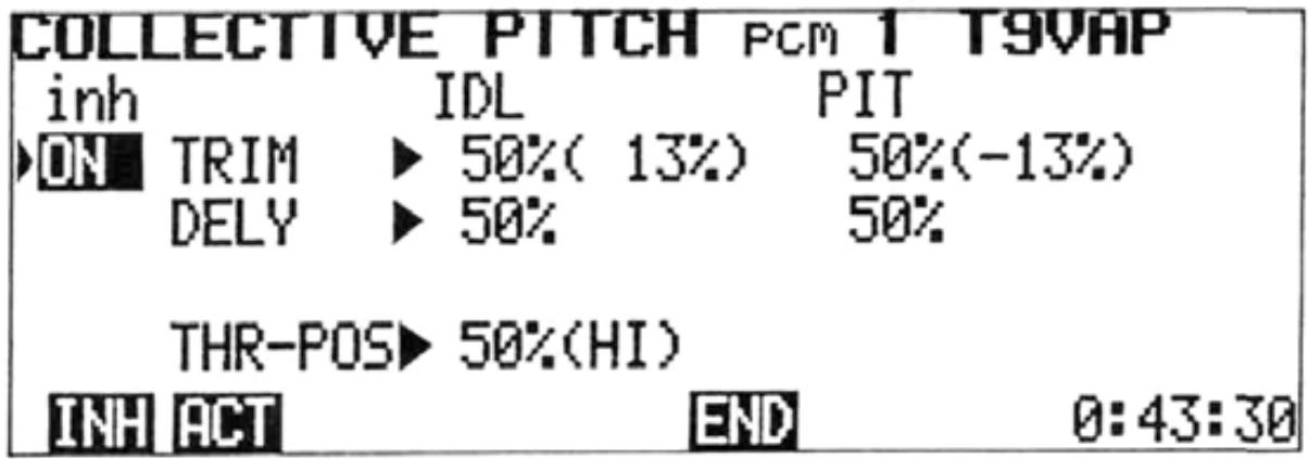
4) The Idle Trim Lever adjusts the engine speed at full LOW (Reverse) pitch.
5) The Pitch Trim Lever adjusts the full HIGH pitch setting at high throttle stick position.
6) The Idle and Pitch trim rates determine the amount of adjustment available with full stroke of the trim lever.
7) Move the cursor to the IDL and PIT TRIM positions with the or cursor key. Set the rates with the + , - , or 100 program key. Figures in ( ) represent the total amount actually set.
8) The Idle Delay provides an adjustable delay in throttle servo movement to prevent the engine from over-reving when the throttle control stick is moved from LOW to HIGH.
9) The Pitch Delay provides a slight delay in pitch servo movement to prevent engine over-reving as the control stick is move from HIGH to LOW.
10) Move the cursor to the IDL and PIT DELY position with the , , , and cursor keys and set the amount of delay with the , or 100 program keys.
11) Set the throttle stick mixing point (point at which the pitch servo moves from low to high).
a) Move the cursor to the THR-POS line with the or cursor key.
b) Set the throttle stick to the desired pitch change position (2 to 3 detents above full idlesuqqested).
c) Press the ENT key to memorize the pitch change position.
12) To return to the original MIXING screen, press the END program key.
NOTE: PITCH-MIX is not available in the BASIC mixing mode.
ADJUSTMENTS AND FLIGHT TECHNIQUES

Elevator-> Flap Mixing
Elevator -> Flap coupling can be helpful in square-cornered loops. A small amount of flap deflection can make circular patterns smoother. CH2 and CH6 are used and the flaps are usually set to move DOWN with application of UP elevator.
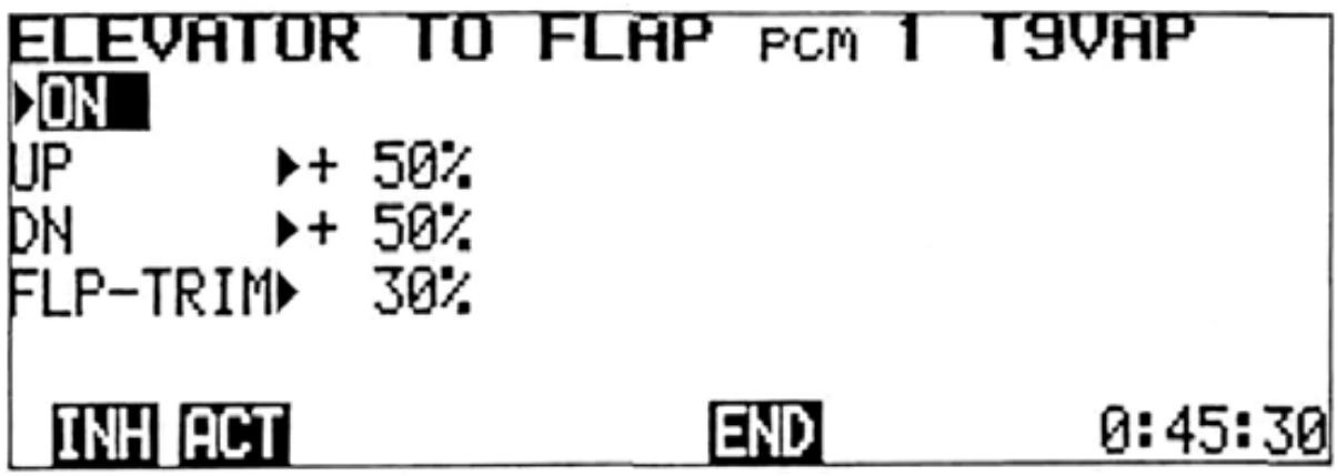
Setting Method
1) Select the EDIT screen and move the cursor to Line 2 with the cursor key, then display the MIXING screen by pressing the MIX program key. Move the cursor to the 2ND line with the cursorkey.
2) Press the 6 program key.
NOTE: 2 ->6 MIX cannot be used in the BASIC mixing mode.
3) To activate the Elevator -> Flap mixing function, press the ACT program key. If the 2 -> 6 MIX Switch is ON at that time, "ON" will be displayed. If the 2 -> 6 MIX Switch is OFF, then "OFF" will be displayed. To deactivate the function, press the INH program key.
4) Set the mixing rate by moving the cursor to the UP or DN line with the + or ↓ cursor key and setting the Flap throw with the +, -, or 100 program key. To change the servo operating direction, move the cursor to the UP line and press the + or - key.
5) Set the Flap Trim throw by moving the cursor to the FLP-TRIM line with the + or ↓ cursor key and setting the throw with the +, -, or 100 program key.
6) Return to the mixing screen by pressing the END program key.

TRIM
- Trim Authority
When Trim adjustments are too sensitive (Ex: One notch on the trim lever in either direction is too much) the Trim Rate (Authority) can be reduced, allowing finer adjustments.
ATL
This type of trim is most useful on the Throttle channel. When the ATL function is used, the trim lever will affect only the extreme LOW throttle servo position. The servo position at HIGH throttle is unaffected by the trim. Therefore, the idle speed can be easily adjusted, while the full throttle opening remains the same.
Cross Trims
Whether or not the Throttle (CH3) and Elevator (CH2) trim levers are "crossed" can be selected.
- Trim Memory
Trim settings can be memorized by the computer, allowing the trim levers to be returned to neutral position. The trim settings can be left stored on the same program while flying other models, and may also be copied to other programs in the transmitter memory.
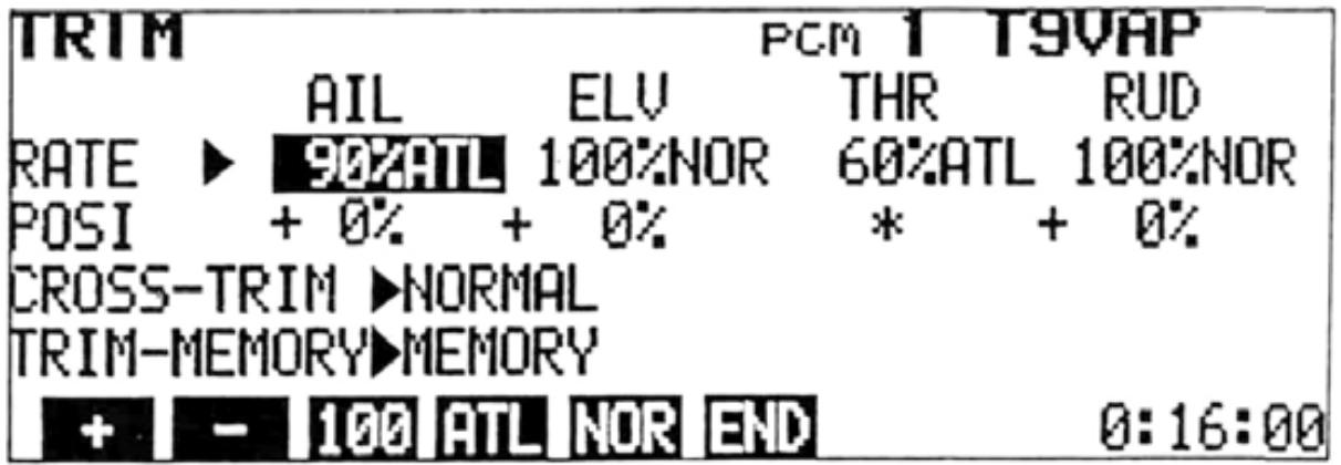
Setting Method
1) Select the EDIT screen and move the cursor to Line 2 with the or cursor key, and display the TRIM screen by pressing the TRM program key.
2) Move the cursor to the RATE line and use the and cursor keys to select the channel to be set. Select normal trim or ATL with the NOR or ATL program key and set the Trim Rate (Authority) with the +, -, or 100 program key. Trim throw can be adjusted from 30% to 100% of normal. Pressing the 100 key will return the rate to 100% .
3) The trim position will be displayed on the POSI line (except in the ATL mode).
4) If "crossed" trim levers are desired (Elev. trim lever controls throttle trim and the normal throttle trim lever controls elev. trim), move the cursor to the CROSS-TRIM line and press the CRS program key.
ADJUSTMENTS AND FLIGHT TECHNIQUES
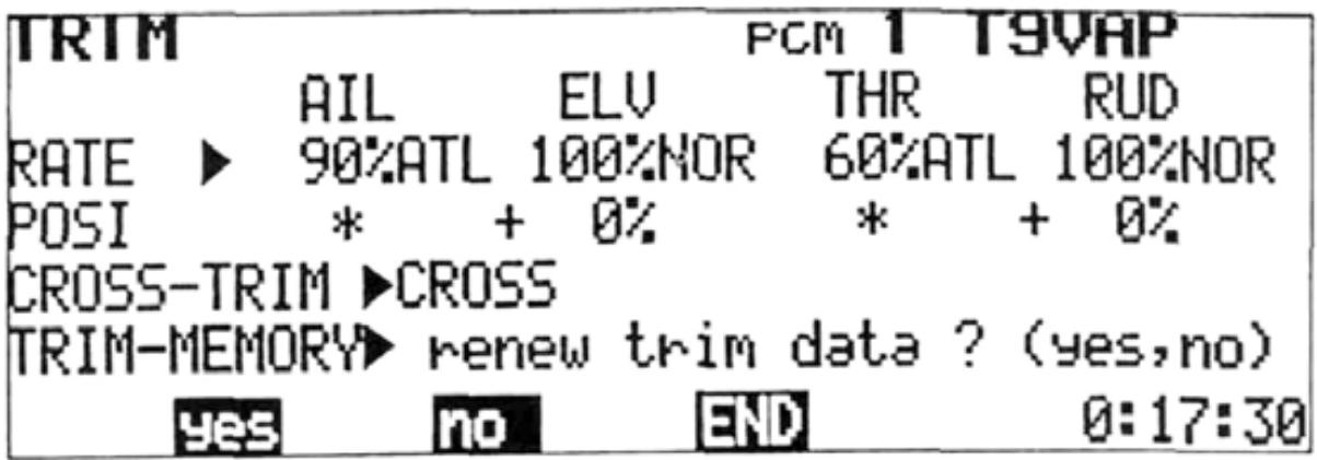
Trim Memory
1) After the model is "trimmed out" and flying well, land and select the TRIM screen.
2) Move the cursor to the TRIM-MEMORY line and press the MEM program key. A message will be displayed asking if the trim data is to be renewed. Press the YES program key. All trim positions are then "memorized" by the computer.
3) All trim levers featuring Trim Memory can then be returned to their neutral positions. When the AIL, ELEV, RUD, AND THR Trim Levers are moved to their neutral positions, a softer "click" will be felt. When a sub trimmer
is moved slowly to the neutral position, a tone will sound indicating the electrical neutral. Positions displayed on the POSI line of the TRIM screen should then be equal to those displayed before pressing the YES key.
a) Control Stick Trim (Except ATL trim)
b) Eight sub trimmers on the trimmer panel
Servo Test: Each servo is operated in linear fashion from neutral, to its maximum and minimum positions. The operation is repeated sequentially for Channels 1 through 8.
Mixing Mode: In the BASIC mode, all mixing circuits except Programmable Mixing are deactivated. In the AERO mode, all circuits are useable.
PCM/PPM: PCM or PPM encoding can be selected with this function. PPM encoding allows the transmitter to be used with standard FM receivers.
D/R SW D/R: The ON/OFF directions of the D/R Switches can be selected. In Mode 1, the upper position is the D/R ON (low rate) position, and in Mode 2, the lower position is the ON position.
9CH SW POS: The position of the CH9 switch can be selected. In SW POS 1, the CH9 Switch becomes the RUD D/R switch position. For SW POS 2, the CH9 Switch position is at the CH5 switch and CH5 is controlled by the CH7 Knob. (Therefore, when AIL DIFF mixing is used, all 9 channels can be used effectively.)

Setting Method
1) Select the EDIT screen and move the cursor to Line 2 with the cursor key, then display the PARAMETER screen by pressing the PAR program key.
2) Servo Test: Move the cursor to the SERVOTEST position with the cursoror key. Turn the function ON and OFF with the ON and OFF program keys.
3) MIX-MODE: Move the cursor to the MIX-MODE position with the cursoror key. Select either the BASIC or AERO mixing mode by pressing the BAS AER programor key.
4) PCM/PPM: Move the cursor to the PCM/PPM position with the + cursorkeyandor select the desired encoding method by pressing the PCM PPM programkey.or
NOTE: Encoding will not change until the transmitter is turned OFF and back ON again.
5) Dual Rate Switch Direction: Move the cursor to the D/R SW DIR position and select Mode 1 or Mode 2 with the 1 or 2 program key.
6) Channel 9 Switch Position: Move the cursor to the 9CH SW POS position and select SW POS 1 or 2 with the 1 program key.
7) Return to the EDIT screen by pressing the END program key.
ADJUSTMENTS AND FLIGHT TECHNIQUES

MODEL SELECT
Model Select Functions
1) Settings and data for up to 6 different models can be stored independently in the transmitter memory.
2) Any one of the 6 programs (models) can be selected for use when desired.
3) Each model can be given a name of up to 8 characters using the NAME function (See page 47).
4) After the Trim Memory function has been performed, the trim positions for each model can be read by selecting the desired model and setting each trimmer to the center position. Then the best setting for up to six models can be re-read.
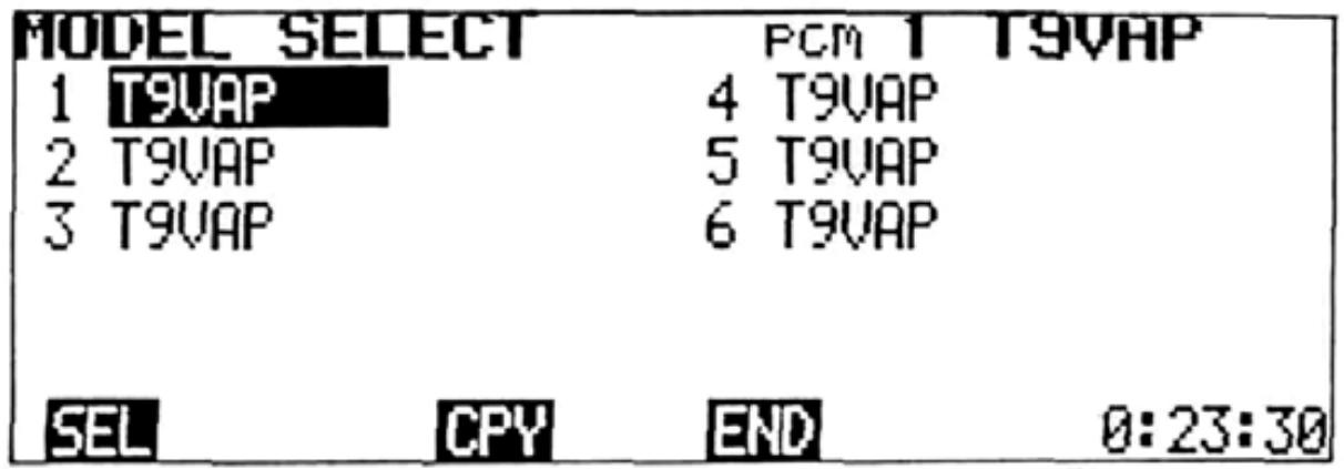
Setting Method
1) Select the EDIT screen and move the cursor to Line 2 with the cursorkey, or and display the MODEL SELECT screen by pressing the MDL program key. The position of the cursor will then indicate the model currently selected.
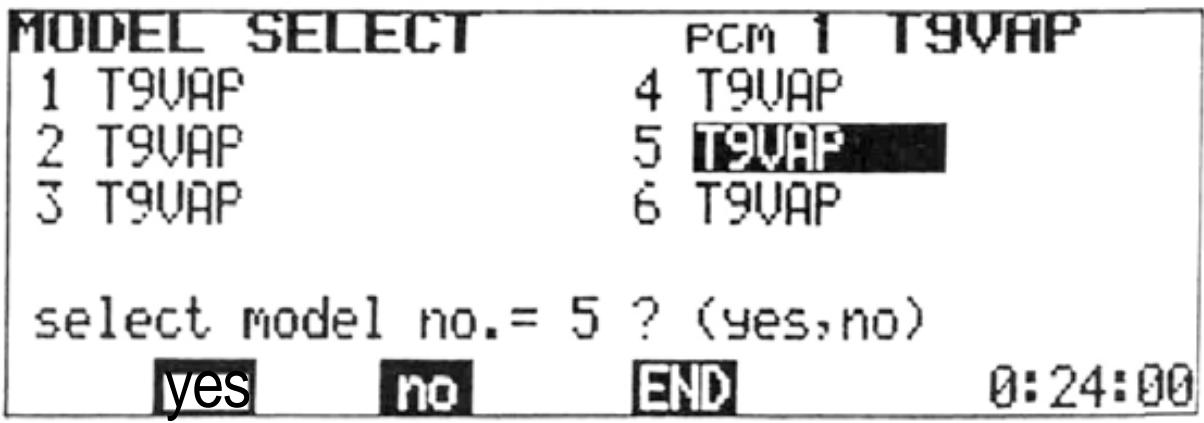
2) Select the desired model number with the
, , , and cursor keys and press the SEL program key. A message asking if the selection is to be executed will be displayed. To execute the selection, press the [yes program key. When the yes program key is pressed, the model number and name at the top right corner of the screen change to show the new selection.
In the example shown, the message asks if model No. 5 is to be selected. To select Model No. 5, the yes soft key is pressed. To remain with Model No. 1, the no program key is pressed.
-MODEL COPY FUNCTION
- The Copy function allows the programmed data and trim positions for one model to be duplicated in their entirety on another program (model) number. As an example, let's suppose that Aircraft No. 1 is properly-trimmed and flys well, but you wish to experiment with a different mixing or trim setting. The Model No. 1 data can be copied onto the Model No. 2 program. You can then make the experimental trim modification on the Model No. 2 program only. The original settings will be retained as is, on the No. 1 program. The MODEL SELECT function can then be used to easily switch back and forth between the old and new setting for comparison (although not in-flight).
- As another alternative, settings for a given model could be copied on two or more programs with modifications for different weather conditions, maneuver schedules, etc.
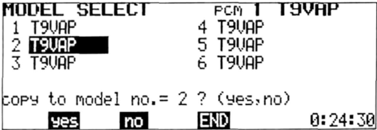
Setting Method
1) Perform the Model Select function to select the Model No. that you wish to copy.
2) Move the cursor to the program No. that you wish to copy the data onto, and press the CPY program key.
3) A message will appear asking if the data is to be copied, (in the example shown, the Model No. 1 data is to be copied to the Model No. 2 program slot.)
4) Press the yes key to execute the copy function or the no key to cancel.
NOTE: Perform the TRIM MEMORY function before copying. The trim levers can then be set to the neutral position.


NAM SRV RES
END
Move the cursor to Line 3 of the EDIT screen with the cursor key.

NAME
A model name of up to 8 characters and a user name of up to 10 characters can be input. The user name has a security feature. Once a four-digit ID number is input, the user name cannot be changed unless the same ID code in input first (The ID code does not appear on the screen after the initial input).
The model name and user name are initially set to T9VAP and FUTABA, respectively.
The model name and user name are displayed at the top right and left corners of the screen. The user name is displayed on the standard screen only.
NOTE: CODE number 0000 is an open code and the user name can be changed. For example, if 1234 is set as your personal ID code number, it is memorized, together with your name, and the user name cannot be changed if the code number 1234 is not input first.
DO NOT FORGET YOUR CODE NUMBER!!!
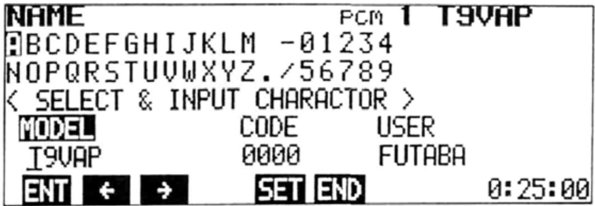
Setting Method
1) Select the EDIT screen and move the cursor to Line 3 with the + cursor key, then display the NAME screen by pressing the NAM program key.
2) Use the , , , and cursor keys to move the cursor to each letter or character to be input.
3) To input the model name, select each character as in Step 2 and press the ENT program key. The character will then appear above the underline and the underline will automatically move to the next space.
4) Up to 8 characters can be input by repeating steps 2) and 3). At the completion of the model name, press the SET program key.
5) To input your personal ID Code, move the lower cursor and the underline to the CODE position with the or program key
and repeat Steps 2) and 3) to input the characters. Up to four characters can be input. When all code characters are input, press the SET key.
6) Next, move the cursor to the USER input position with the or program key, and a user name of up to 10 characters can be input (Steps 2 and 3). At the completion of the user name input, press the SET key.
7) When the NAME screen is again selected after the ID code has been set the code will NOT be displayed. The code and user name cannot be changed unless the original code is re-entered (Repeat Step 5 including pressing the SET key). The ID code and user name can then be changed. Therefore, do not forget your ID code.
ADJUSTMENTS AND FLIGHT TECHNIQUES

SERVO (Transmitter Test Mode)
Transmitter control movements are shown on a bar graph representing servo movement for channels 1 through 8. The center of the graph is the neutral position. The bottom half indicates counterclockwise servo rotation and the top half represents clockwise rotation.
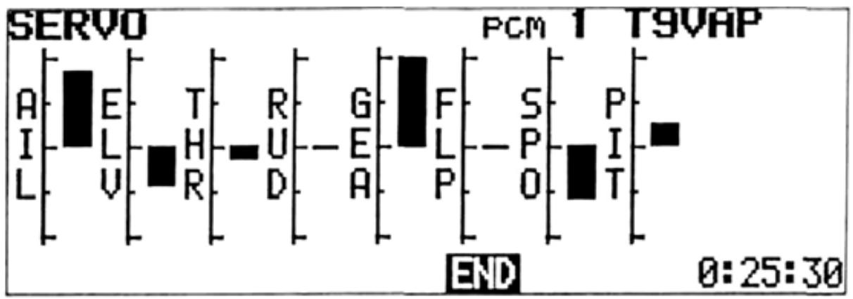
Setting Method
1) Select the EDIT screen and move the cursor to Line 3 with the cursor key, then display the SERVO screen by pressing the SRV program key.
2) Bar graphs proportional to the servo throw can be observed by operating the control sticks, levers, and switches of each channel of the transmitter (1 to 8). This can be used to test the performance of the transmitter, and check the effect of new settings and data inputs.
The RESET function can be used to return programmed data to the original factory settings. Certain functions can be reset individually (Items 1-7 below), or all data can be reset in a single operation (Item 8).
Functions to be Reset:
- REV, F/S 5. MIX
- ATV 6.TRM
3.AFR 7.PAR - D/R, EXP 8. ALL
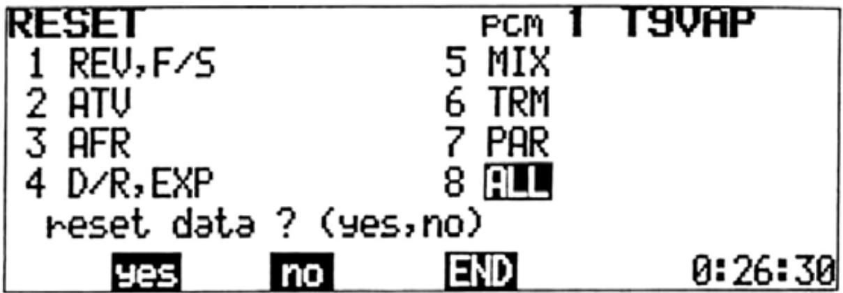
ALL resets Items 1 through 7 simultaneously.
Setting Method
1) Select the EDIT screen and move the cursor to Line 3 with the + cursor key, then press the RES program key.
2) Move the cursor to the Item No. to be reset with the , , , or cursor keys.
3) Press the RES program key. A message will appear asking if the data is to be reset.
4) To complete the RESET operation, press the yes program key. To cancel the operation, press the no key.
•SPLINED HORN
The splined horns allow adjustment of the servo neutral position at the servo horn.
Neutral position adjustment
a) Angle divisions
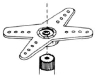
1) The splined horn has 25 segments. The amount of change per segment is; 360 - 25 = 14.4
2) The minimum adjustable angle is determined by the number of arms or number of holes. For four arms, the minimum adjustable angle is:
$$ 3 6 0 ^ {\circ} \div \frac {(2 5 \times 4)}{\text {N u m b e r o f d i v i s i o n s}} = 3. 6 ^ {\circ} $$
b) Effect
To shift the holes center line to the right (clockwise) relative to baseline A, shift arm 2 to the position of arm 1 and set it to the position closest to baseline A.
(Example) For a four arm horn, the angular shift per segment is 14.4^ . The shift to the right is: 90^ - (14.4 × 6) = 3.6^
To shift by the same angle in the opposite direction, use the opposite arm number.
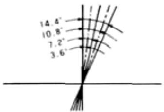
For a six arm horn, turn the arm counterclockwise and set arm 2 to the position of arm 1.
The adjustable angle is 60 - (14.4 × 4) = 2.4^ .
Arm 3 shifts 4.8^ to the right, arm 6 shifts 2.4^ to the left, and arm 4 shifts 7.2^ to the right and left.
The following splined horns are optional.
HORN A (FSH-6X)

HORN B (FSH-6S)
HORN C (FSH-6R)

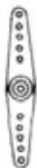
HORN D (FSH-6W)
HORNE
HORN F
HORNG
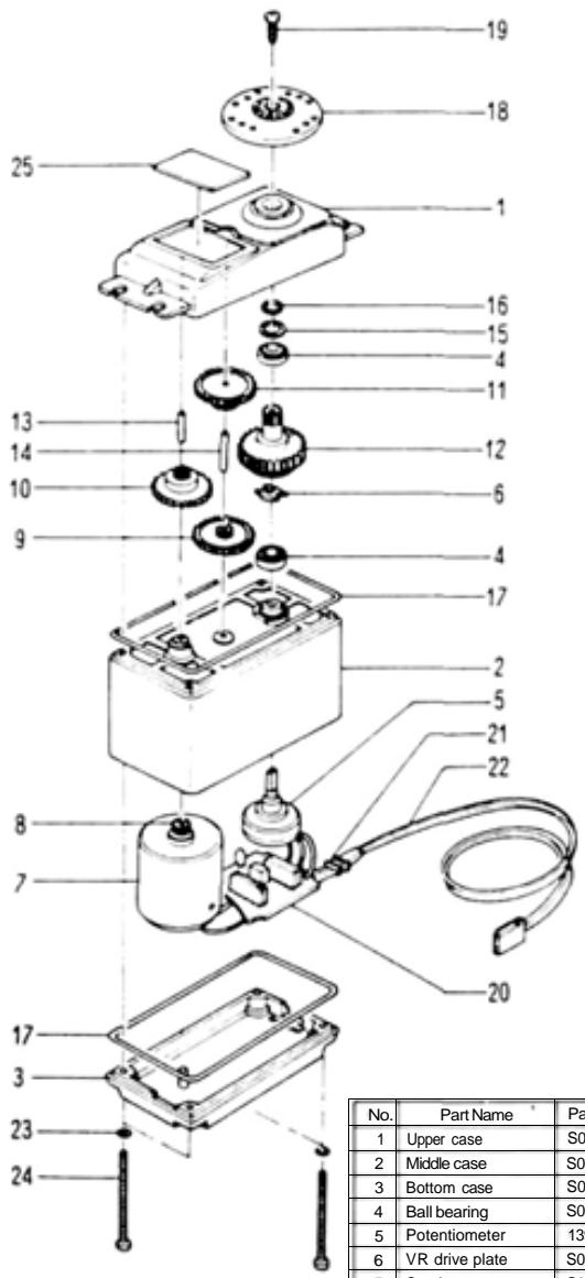
-FP-S9101
-EXPLODED VIEW
-FP-S5101
-EXPLODED VIEW
| No. | Part Name | Pan No. |
| 1 | Upper case | S05740 |
| 2 | Middle case | S05750 |
| 3 | Bottom case | S05760 |
| 4 | Ball bearing | S04130 |
| 5 | Potentiometer | 139995 |
| 6 | VR drive plate | S02753 |
| 7 | Coreless motor | S91265 |
| 8 | Motor pinion | S02497 |
| 9 | 1st gear | S02805 |
| 10 | 2nd gear | S02466 |
| 11 | 3rd gear | S02467 |
| 12 | Final gear | S02806 |
| 13 | 2nd shaft | S02481 |
| 14 | Intermediate shaft | S02480 |
| 15 | Spacer washer 0.3T | S02486 |
| 16 | Seal ring | S90415 |
| 17 | 0-ring | S90417 |
| 18 | Servo horn D | S01239 |
| 19 | Horn mounting screw | J55178 |
| 20 | S9101 AMP.S150 | AS1333 |
| 21 | Lead wire packing | S90045 |
| 22 | 3PBG.WRB-300B | AT2238 |
| 23 | Screw0-ring | S90410 |
| 24 | Case mounting screw | J50085 |
| 25 | S9101 primed wiring board | S60093 |
| No. | Part Name | Part No. |
| 1. | Upper case | FCS-30 |
| 2. | Middle case | FCS30 |
| 3. | Bottom case | FCS30 |
| 4. | Ball bearing | S04130 |
| 5. | Potentiometer | 139995 |
| 6. | VR drive plate | S02753 |
| 7. | Motor | S91252 |
| 8. | Motor pinion | S02461 |
| 9. | 1st gear | FGS 30 |
| 10. | 2nd gear | FGS 30 |
| 11. | 3rd gear | FGS 30 |
| 12. | Final gear | FGS30 |
| 13. | 2nd shaft | S02481 |
| 14. | Intermediate shaft | S02480 |
| 15. | Spacer washer 0.3T | S02486 |
| 16. | Seal ring | S90415 |
| 17. | O-ring | S90417 |
| 18. | Servo horn D | FSH-6W |
| 19. | Horn mounting screw | FSH-41 |
| 20. | S printed wiring board | AS 1308 |
| 21. | Lead wire packing | S90045 |
| 22. | 3PB-WRB-300 | FPC-8M |
| 23. | Screw 0 ring | S90410 |
| 24. | Case mounting screw | J50085 |
| 25. | S5101 Nameplate | S60199 |
This soft map shows which soft key changes which
function key
Use it when setting data.
T9VHP SOFT MAP 1
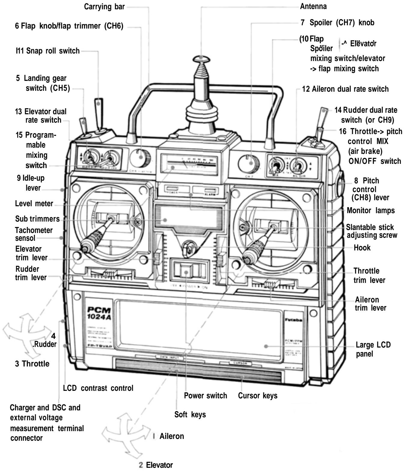
T9VAP TRANSMITTER CONTROLS
MODE, II
T9VAP SOFT MAP 2
This portable soft map shows which soft keys change to which function keys when a soft key (DATA INPUT key) was pressed. Use it when setting data in the field.
FACTORY REPAIR SERVICE
To insure prompt service, please follow the instructions given below.
- Charge the batteries for at least 18 hours prior to shipment.
- Return the system only. Not your complete installation. Remove the servos from their mounts and remove the foam padding from the receiver.
- Plugs or other modifications which interfere with factory test procedures will be returned to factory standard at your expense.
- Carefully pack all components individually, using sufficient packing material to prevent damage during shipment.
- Include a brief but thorough explanation of all problems and service required and tape it to the back of the transmitter. Place a label describing the function of the servo on each servo.
- Be sure to include your full address and tel. No., zip code inside the box as well as on the outside.
- Include a packing list of all items being returned, and double check to make sure that all items are packed.
- Upon receipt of your equipment at the Futaba factory, an estimate of the cost of repair (over $25.00 only) will be sent to you. Your equipment will then be repaired and returned to you upon receipt of payment or C.O.D, (cash).
This factory repair service applies only to the continental U.S.A., Hawaii, and Alaska.


Tokyo Office: Inagaki Bldg., 3F 1-21-3, Kanda Suda-cho, Chiyoda-ku, Tokyo 101, Japan
Phone: (03) 3255-6811 Facsimile: (03) 3255-6880