14MZ - Radio transmitter for modeling FUTABA - Free user manual and instructions
Find the device manual for free 14MZ FUTABA in PDF.
| Product type | Radio transmitter for modeling |
| Brand | FUTABA |
| Model | 14MZ |
| Operating system | Windows CE |
| Modulation type | PCM-G3, PCM1024, selectable FM/PPM |
| Number of channels | 14 |
| Transmission frequency | 72 or 50 MHz band (US) |
| Transmitter power supply | Lithium-Ion battery 7.4 V / 2200 mAh (LT2F2200) |
| Receiver power supply | Ni-Cd battery 4.8 V (NR4F1500) |
| Display | HVGA color LCD (640x240 pixels) with backlight |
| Memory | Compact Flash (CF) card 32 MB included |
| Mixing functions | Programmable, multiple curves, up to 8 flight conditions |
| Special functions | Voice recording, WMA music playback, image display |
| Receiver | R5014DPS (14 channels, synthesized, PCM-G3) |
| Safety | Fail-Safe function, throttle cut, user lock |
| Maintenance | Charge batteries before use, avoid moisture |
| Included accessories | CFDP32M card, LBC-1D5 charger, Ni-Cd charger, cables, carrying case |
| Receiver dimensions | 52 × 37.5 × 16.5 mm |
| Receiver weight | 33 g |
| Operating temperature | Do not expose to excessive heat (max 60°C) |
| Spare parts | Batteries, charger, CF card, antenna, switches |
| Repairability | Futaba service center, annual service recommended |
| Usage | Aircraft and helicopter modeling |
| Certifications | FCC (United States) |
Frequently Asked Questions - 14MZ FUTABA
User questions about 14MZ FUTABA
0 question about this device. Answer the ones you know or ask your own.
Ask a new question about this device
Download the instructions for your Radio transmitter for modeling in PDF format for free! Find your manual 14MZ - FUTABA and take your electronic device back in hand. On this page are published all the documents necessary for the use of your device. 14MZ by FUTABA.
USER MANUAL 14MZ FUTABA
- Support and Service 4
Application, Export, and Modification. 5 - Definitions of Symbols 6
- Safety Precautions (do not operate without reading) 6
BEFORE USE 9
-Features of 14MZ 9
- Contents and technical specifications 11
- Accessories. 12
- Transmitter controls 13
Cautions on handling antenna 13
LED monitor 14
Switch reallocation (SA-SH) 14
Volume (LD, CD, RD) 15
Slide Lever (LST, LS, RS, RST). 15
Digital trim (T1-T6) 16
Touch panel/Rotary key/Direct key 16
Stick Adjustment 17
CF card CFDP32M 18
Connector/Plug 19
USB port (*This port is for factory use only.) 19
Attachment and detachment of the battery .... 20
RF module MZ-FM. 21
Toolbox 21
- Receiver nomenclature 22
- Safety precautions when installing receiver and servos 23
BASIC OPERATION 24
Battery Charging 24
How to charge the Lithium Ion Battery 24
How to charge the Ni-Cd Battery. 24
- How to turn On/OFF the transmitter............ 25
When turning on 25
When turning off 25
How to reset 26
How to change the frequency/How to set the receiver's ID 26
- In case of using PCM1024, PPM receivers... 27
- Registration of the user's name. 27
Home screen 28
Music play back. 29
FUNCTIONS OF SYSTEM MENU 30
Trainer 31
Display 33
Date & Time 34
User Name. 35
Switch. 36
HW Reverse 37
Information 38
MODEL BASIC SETTING PROCEDURE ...39
Airplane/glider basic setting procedure. 39
- Helicopter basic setting procedure 41
- Receiver and servos connection 45
Servo connection by model type. 46
FUNCTIONS OF LINKAGE MENU 50
(Common Functions)
Linkage Menu functions table. 50
Servo Monitor 51
Model Select 52
Model Type 53
Picture 55
Sound 56
Frequency 58
Function 59
Sub-Trim 61
Servo Reverse 62
Fail Safe 63
End Point (ATV) 64
Throttle Cut (Airplane/helicopter only) 65
Idle Down (Airplane/helicopter only) 66
Swash (Helicopter only). 67
Timer 69
Dial Monitor. 70
Data Reset 71
FUNCTIONS OF MODEL MENU
Common Functions 72
Servo Monitor (Linkage Menu 51)
Condition Select. 73
Condition Hold. 74
AFR (D/R). 75
Program Mix 77
Fuel Mixture. 79
Airplane/Glider/EP Glider Functions. 80
Model Menu functions list 80
AIL Differential. 82
Flap Setting 83
AIL to Camber FLP. 84
AIL to Brake FLP. 85
AIL to RUD. 86
Airbrake to ELE 87
RUD to AIL. 88
Camber Mix 89
ELE to Camber. 91
Camber FLP to ELE. 92
Butterfly 95
TrimMix1/2 95
Airbrake 97
Gyro 99
V-tail. 100
Ailevator. 101
Winglet 102
Motor. 103
RUD to ELE. 104
Snap Roll. 105
Multi Engine 106
- Helicopter Functions 107
Model Menu functions list 107
PIT Curve 108
THR Curve 111
Acceleration 113
Throttle Hold. 114
Swash Mix. 115
Throttle Mix 116
PIT->Needle 117
PIT RUD. 118
Gyro 119
Governor 120
Common Operations used in function setup screen 121
INTRODUCTION
Thank you for purchasing the Futaba® 14MZ series digital proportional R/C system. In order for you to make the best use of your system and to fly safely, please read this manual carefully. If you have any difficulties while using your system, please consult the manual, our online Frequently Asked Questions (on the web pages referenced below), your hobby dealer, or the Futaba Service Center.
Due to unforeseen changes in production procedures, the information contained in this manual is subject to change without notice.
Support and Service: It is recommended to have your Futaba equipment serviced annually during your hobby's "off season" to ensure safe operation.
IN NORTH AMERICA
Please feel free to contact the Futaba Service Center for assistance in operation, use and programming. Please be sure to regularly visit the 14MZ Frequently Asked Questions web site at http://www.futaba-rc.com/faq/faq/index.html. This page includes extensive programming, use, set up and safety information on the 14MZ radio system and is updated regularly. Any technical updates and US manual corrections will be available on this web page. If you do not find the answers to your questions there, please see the end of our F.A.Q. area for information on contacting us via email for the most rapid and convenient response.
Don't have Internet access? Internet access is available at no charge at most public libraries, schools, and other public resources. We find internet support to be a fabulous reference for many modelers as items can be printed and saved for future reference, and can be accessed at any hour of the day, night, weekend or holiday. If you do not wish to access the internet for information, however, don't worry. Our support teams are available Monday through Friday 8-5 Central time to assist you.
FOR SERVICE ONLY
Futaba Service Center
3002 N. Apollo Drive, Suite 1
Champaign, IL 61822
Phone: 217-398-0007
www.hobbyservices.com
FOR SUPPORT
(PROGRAMMING AND USER QUESTIONS)
Please start here for answers to most questions:
www.futaba-rc.com
FACSIMILE: 217-398-7721
PHONE: 217-398-8970 option 2
OUTSIDE NORTH AMERICA
Please contact your Futaba importer in your region of the world to assist you with any questions, problems or service needs. Please recognize that all information in this manual, and all support availability, is based upon the systems sold in North America only. Products purchased elsewhere may vary. Always contact your region's support center for assistance.
Application, Export, and Modification
-
This product is suitable for model airplane, surface or 50MHz (license required) use, if on the correct frequency. It is not intended for use in any application other than the control of models for hobby and recreational purposes. The product is subject to regulations of the FCC and is restricted under United States law to such purposes.
-
Exportation precautions:
(a) When this product is exported from the country of manufacture, its use is to be approved by the laws governing the country of destination which govern devices that emit radio frequencies. If this product is then re-exported to other countries, it may be subject to restrictions on such export. Prior approval of the appropriate government authorities may be required. If you have purchased this product from an exporter outside your own country and not the authorized Futaba distributor in your country, please contact the seller immediately to determine if such export regulations have been met.
(b) Use of this product with other than models may be restricted by Export and Trade Control Regulations, and an application for export approval must be submitted. In the US, use of 72MHz (aircraft only), 75MHz (ground models only) and 27MHz (both) frequency bands are strictly regulated by the FCC. This equipment must not be utilized to operate equipment other than radio controlled models. Similarly, other frequencies (except 50MHz , for HAM operators) must not be used to operate models.
- Modification, adjustment, and replacement of parts: Futaba is not responsible for unauthorized modification, adjustment, and replacement of parts on this product. Any such changes may void the warranty.
The Following Statement Applies to the Receiver (for U.S.A.)
This device complies with part 15 of the FCC rules. Operation is subject to the following two conditions:
(1) This device may not cause harmful interference.
(2) This device must accept any interference received, including interference that may cause undesirable operation.

The RBRC^TM SEAL on the nickel-cadmium battery contained in Futaba products indicates that Futaba Corporation of America is voluntarily participating in an industry-wide program to collect and recycle these batteries at the end of their useful lives, when taken out of service within the United States. The RBRC program provides a convenient alternative to placing used nickel-cadmium batteries into the trash or municipal waste system, which is illegal in most areas.
You may contact your local recycling center for information on where to return the spent battery. Please call 1-800-8-BAT- TERY for information on battery recycling in your area. Futaba Corporation of America's involvement in this program is part of it's' commitment to protecting our environment and conserving natural resources.
NOTE: Our instruction manuals encourage our customers to return spent batteries to a local recycling center in order to keep a healthy environment. RBRC is a trademark of the Rechargeable Battery Recycling Corporation.
Definitions of Symbols
Pay special attention to safety where indicated by the following symbols.
DANGER - Procedures which may lead to dangerous conditions and cause death/serious injury if not carried out properly.
WARNING - Procedures which may lead to a dangerous condition or cause death or serious injury to the user if not carried out properly, or procedures where the probability of superficial injury or physical damage is high.
CAUTION - Procedures where the possibility of serious injury to the user is small, but there is a danger of injury, or physical damage, if not carried out properly.
$$ \bigcirc = \text {P r o h i b i t e d} $$
$$ \mathbf {!} = \text {M a n d a t o r y} $$
Warning: Always keep electrical components away from small children.
FLYING SAFETY
To ensure the safety of yourself and others, please observe the following precautions:
Have regular maintenance performed. Although your 14MZ protects the model memories with non-volatile EEPROM memory (which does not require periodic replacement) and not a battery, it still should have regular checkups. We recommend sending your system to the Futaba Service Center annually during your non-flying season for a complete checkup and service.
Use the Fail-Safe safety feature to set the throttle to low-idle In case of signal loss or RX battery failure. Engine power will be automatically reduced to help limit personal or property damage. Refer to the Failsafe Setting Procedure listed in the index.
Receiver Ni-Cd Battery
Charge the batteries! (See Charging the batteries listed in the index for details.) Always recharge the receiver batteries for at least 8 hours before each flying session. A low battery will soon die, causing loss of control and a crash. When you begin your flying session, reset your timer, and during the session pay attention to the duration of usage.
CAUTION: The initial charge on new NiCd receiver batteries should be done for 15 hours using the slow-charger that came with the radio system. This will "condition" the batteries so that the next charge may be done using the fast-charger of your choice. If the initial charge is done with a fast-charger the batteries may not reach their full capacity and you may be flying with batteries that are only partially charged.
Where to Fly
We recommend that you fly at a recognized model airplane flying field. You can find model clubs and fields by asking your nearest hobby dealer, or in the US by contacting the Academy of Model Aeronautics. You can also contact the national Academy of Model Aeronautics (AMA), which has more than 2,500 chartered clubs across the country. Through any one of them, instructor training programs and insured newcomer training are available. Contact the AMA at the address or toll-free phone number below.
IMPORTANT! The Lithium-Ion (Li-Ion) batteries included in the 14MZ transmitter are not to be confused with Lithium-Polymer (LiPo) batteries, or any other type of rechargeable battery (including NiCd's and NiMH's). Li-Ion batteries require special charging criteria different than other rechargeable batteries. Use only the Futaba lithium ion transmitter charger included with this set for, or other chargers approved by Futaba to charge the Li-Ion batteries in the 14MZ transmitter.
It is important to understand the operating characteristics of lithium-ion (Li-Ion) batteries. Always read the specifications printed on the label of your Li-Ion battery and charger prior to use. Failure to follow the proceeding precautions can quickly result in severe, permanent damage to the batteries and its surroundings and possibly result in a FIRE!
IMPORTANT PRECAUTIONS
Do not attempt to disassemble Li-Ion packs or cells.
Do not allow Li-Ion cells to come in contact with moisture or water at any time.
Always provide adequate ventilation around Li-Ion batteries during charge, discharge, while in use, and during storage.
Do not leave a Li-Ion battery unattended at any time while being charged or discharged.
Do not attempt to charge Li-Ion batteries with a charger that is NOT designed for Li-Ion batteries, as permanent damage to the battery and charger could result.
Always charge Li-Ion batteries in a fireproof location. Do not charge or discharge Li-Ion batteries on carpet, a cluttered workbench, near paper, plastic, vinyl, leather or wood, or inside an R/C model or full sized automobile! Monitor the charge area with a smoke or fire alarm, and have a lithium-approved "ABC type" fire extinguisher available at all times.
Do not charge Li-Ion batteries at currents greater than the "1C" rating of the battery ("C" equals the rated capacity of the battery).
Do not allow Li-Ion cells to overheat at any time! Cells which reach greater than 140 degrees Fahrenheit (60^OC) should be placed in a fireproof location.
It is normal for the batteries to become warm during charging, but if the charger or battery becomes excessively hot disconnect the battery from the charger immediately!! Always inspect a battery which has previously overheated for potential damage, and do not re-use if you suspect it has been damaged in any way.
Do not use a Li-Ion battery if you suspect physical damage has occurred to the pack. Carefully inspect the battery for even the smallest of dents, cracks, splits, punctures or damage to the wiring and connectors. DO NOT allow the battery's internal electrolyte to get into eyes or on skin—wash affected areas immediately if they come in contact with the electrolyte. If in doubt, place the battery in a fire-proof location for at least 30 minutes.
Do not store batteries near an open flame or heater.
Do not discharge Li-Ion batteries at currents which exceed the discharge current rating of the battery.
Always store Li-Ion cells/packs in a secure location away from children.
Compact Flash (CF) Card Handling Instructions Follow these precautions when handling the CF card included in your 14MZ transmitter.
Never remove the CF card or turn off power while entering data.
Do not expose the CF card to dirt, moisture, water or fluids of any kind.
Never store the CF card where it may be subject to strong static electricity or magnetic fields.
Always hold the CF card by the edges during installation and removal.
Do not expose the CF card to direct sunlight, excessive humidity or corrosive environments.
Be certain to insert the CF card in the correct direction.
Always pay particular attention to the flying fields' rules, as well as the presence and location of spectators, the wind direction, and any obstacles on the field. Be very careful flying in areas near power lines, tall buildings, or communication facilities as there may be radio interference in their vicinity. If you must fly away from a club field, be sure there are no other modelers flying within a three-to-five-mile range, or you may lose control of your aircraft or cause someone else to lose control.
Before flying, be sure that the frequency you intend to fly with is not in use, and secure any frequency control device (pin, tag, etc.) for that frequency before turning on your transmitter. It is never possible to fly two or more models on the same frequency at the same time. Even though there are different types of modulation (AM, FM, PCM), only one model may be flown on a single frequency at any one time.
Stop flying long before your batteries become low on charge. Do not rely on your radio's low-battery warning systems, which are intended only as a precaution, to tell you when to recharge. Always check your transmitter and receiver batteries prior to each flight.
To prevent possible damage to your radio gear, turn the power switches on and off in the proper sequence:
- Set the throttle stick to the idle position, or otherwise disarm your motor/engine.
- Fully extend the transmitter antenna.
- Turn on the transmitter power and allow your transmitter to reach its home screen.
- Confirm the proper model memory has been selected.
- Turn on your receiver power.
- Test all controls. If a servo operates abnormally, don't attempt to fly until you determine the cause of the problem. (For PCM systems only: Test to ensure that the Failsafe settings are correct by waiting at least 2 minutes after adjusting then, turning the transmitter off and confirming the proper surface/throttle movements. Turn the transmitter back on.)
- Start your engine.
- Complete a full range check.
- After flying, bring your throttle stick to idle position, engage any kill switches or otherwise disarm your motor/engine.
- Turn off receiver power.
- Turn off transmitter power.
If you do not turn on your system in this order, you may damage your servos or control surfaces, flood your engine, or in the case of electric-powered or gasoline-powered models, the engine may unexpectedly turn on and cause a severe injury.
While you are getting ready to fly, if you place your transmitter on the ground, be sure that the wind won't tip it over. If it is knocked over, the throttle stick may be accidentally moved, causing the engine to speed up. Also, damage to your transmitter may occur.
Before taxiing, be sure to extend the transmitter antenna to its' full length. A collapsed antenna will reduce your flying range and cause a loss of control. It is a good idea to avoid pointing the transmitter antenna directly at the model, since the signal is weakest in that direction.
Don't fly in the rain! Water or moisture may enter the transmitter through the antenna or stick openings and cause erratic operation or loss of control. If you must fly in wet weather during a contest, be sure to cover your transmitter with a waterproof barrier. Never fly if lightning is expected.
! Never turn the transmitter off during flight! Switching the transmitter off and on during flight will very likely cause a crash because of the time required for the transmitter to "reboot" and become fully functional.
FEATURES
PCMG3 (PCM Generation 3)
PCMG3 has a 40% faster response than current PCM1024. The resolution is 2048, which is double the current PCM1024. It can operate up to 14 Channels. The multi-level modulation technology has been implemented for the R/C industry to achieve the highest performance available today.
WindowsCE
T14MZ utilizes the world famous Microsoft WindowsCE, which offers outstanding dependability and valuable resources.
Color LCD
T14MZ has a HVGA (640x240 pixels) wide screen full color LCD. It has a backlight and the screen is manufactured of a transflective construction which enables both indoor and outdoor visibility.
Music Play
T14MZ can playback WMA (Windows Media Audio) files on a CF-Card. You can enjoy music by the internal speaker or stereo headphone from the earphone jack, and you can assign switches to start/stop your music. You can download the WMA files of your own music from your PC.
Voice Recording
You can record your own voice by internal microphone and then play back commands to be assigned to certain switches. Recording time is 3 seconds maximum and 24 voice files can be stored.
Picture Image Pasting
You can paste picture image files (168x80 pixels) taken by digital camera to the model screen. Enabling you to download any image you like on your home screen.
Compact Flash
The model data and music files, voice files, picture image files are stored to Compact flash (CF) card. The memory size is 32 MB. Futaba prepares industrial rating CF cards.
WFSS (Wireless Frequency Setting System)
The construction of both transmitter (T14MZ) and receiver (R5014) are a frequency synthesizer system.
Editing
The touch panel and rotary encoder editing system will allow you to edit your model in the manner that is easiest and most functional for you.
Functions
The internal dual processors operate the many 14MZ FEATURE functions and optimize the response time. Most of the mixing functions are operated by curves which give you more precise settings.
Stick
Each axis is supported by dual ball bearings. This allows for finer and more precise operation, the new potentiometers also offer longer life.
Replaceable switches
You can replace 8 of the toggle switches on the right and left shoulder, with optional switches (two position, three position, and momentary etc.).
Li-ion battery
T14MZ is operated by 7.4V / 2,200mAh Lithium-Ion battery.
R5014DPS
The R5014DPS is a small 14CH synthesized receiver with high sensitivity and selectability.
Contents and Technical Specifications
(Specifications and ratings are subject to change without notice.)
Your 14MZAP or 14MZHP (packaged with a 14-channel PCM-G3 receiver) includes the following components:
- T14MZ Transmitter, including RF module (MZ-DDS)
R5014 Receiver
CFDP32M Data-Pack (CF card)
LT2F2200 Li-ion battery & LBC-1D5 Charger - NR4F1500 Ni-Cd battery & 110V wall charger (North America)
- Switch harness/Aileron extension cord/Y-harness/DSC cord
- Tool Box (includes special jig for adjustment)
- Neck strap
Frequency Flag
The set contents depend on the type of set.
Transmitter T14MZAP/HP
Operating system: 2-stick, 14 channels, PCM-G3, synthesizer system
Transmitting frequency: US only 72 or 50MHz bands
Modulation: PCM-G3, PCM1024, or FM/PPM switchable.
Power supply: 7.4V LT2F2200 Li-ion battery
Current drain: 1 ampere maximum (RF power on and back light on) 700mA average
Receiver R5014DPS
(PCM-G3, Synthesizer, Dual conversion)
Receiving frequency: US only 72 or 50MHz bands
Intermediate freq.: 10.7MHz & 450kHz
Power requirement: 4.8V Ni-Cd battery
Current drain: 75mA
Size: 52 × 37.5 × 16.5 ~mm
Weight: 33g
Channels: 14
Suggested Servos for use with your 14MZ
Servo S9154 (Digital servo)
Control system: Pulse width control, 1.52ms neutral
Power requirement: 4.8V (from receiver)
Output torque: 63.9 oz.-in. (4.6 kg-cm) at 4.8V
Operating speed: 0.14 sec/60 at 4.8V
Size: 1.87 × 1.06 × 0.97 in. (47.5 × 27.0 × 25.3 ~mm)
Weight: 1.87 oz. (53 g)
Servo S9151 (Digital servo)
Control system: Pulse width control, 1.52ms neutral
Power requirement: 4.8V (from receiver)
Output torque: 131.9 oz.-in. (9.5 kg-cm) at 4.8V
Operating speed: 0.19 sec/60 at 4.8V
Size: 1.57 × 0.79 × 1.44 in. (40.0 × 20.0 × 36.6 ~mm)
Weight: 1.79oz (50g)
Servo S9250 (Digital servo)
Control system: Pulse width control, 1.52ms neutral
Power requirement: 4.8V (from receiver)
Output torque: 76.4 oz.-in. (5.5 kg-cm) at 4.8V
Operating speed: 0.11 sec/60 at 4.8V
Size: 1.59 × 0.79 × 1.48 in. (40.5 × 20.0 × 37.5 ~mm)
Weight: 1.90oz (54g)
Servo S9255 (Digital servo)
Control system: Pulse width control, 1.52ms neutral
Power requirement: 4.8V (from receiver)
Output torque: 125.0 oz.-in. (9.0 kg-cm) at 4.8V
Operating speed: 0.16 sec/60 at 4.8V
Size: 1.57 × 0.79 × 1.44 in. (40.0 × 20.0 × 36.6 ~mm)
Weight: 1.94 oz. (55 g)
The following additional accessories are available from your dealer. Refer to a Futaba catalog for more information:
- Compact Flash Memory card - CFDP 32M Data-Pack increases your model, music file, voice file, and picture image file storage capability, and allows you to transfer model settings to another T14MZ transmitter.
- LT2F2200 Transmitter battery pack - the (2200mAh) transmitter Li-ion battery pack may be easily exchanged with a fresh one to provide enough capacity for extended flying sessions.
- Trainer cord - the optional training cord may be used to help a beginning pilot learn to fly easily by placing the instructor on a separate transmitter. Note that the T14MZ transmitter may be connected to another T14MZ system, as well as to any other models of Futaba transmitters. The T14MZ transmitter uses the newer "Micro" rectangular type cord plug. Both Micro- to-Micro and Micro-to-round plug style trainer cords are available.
- Neckstrap - a neckstrap may be connected to your T14MZ system to make it easier to handle and improve your flying precision since your hands won't need to support the transmitter's weight.
- Y-harnessed, servo extensions, etc - Genuine Futaba extensions and Y-harnessed, including a heavy-duty version with heavier wire, are available to aid in your larger model and other installations.
- Gyros - a variety of genuine Futaba gyros are available for your aircraft or helicopter needs.
- Governor (GV1) - for helicopter use. Automatically adjusts throttle servo position to maintain a constant head speed regardless of blade pitch, load, weather, etc.
- DSC Cord - allows setup and testing without transmitting. With your Transmitter and Receiver off, plug cord into trainer port then, into the receiver Battery/DSC (B/C) slot. All programming and setup may be done in this manner without transmitting.
- Receivers - various models of Futaba receivers may be purchased for use in other models. (Receivers for PCM-G3, PCM1024, or FM/PPM types are available.)
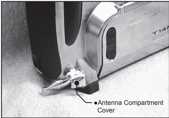
Transmitter controls
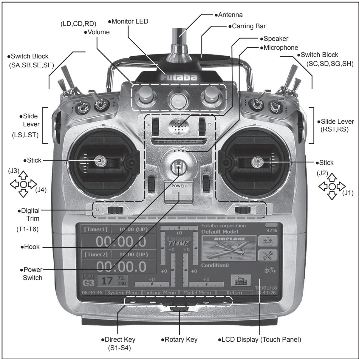
Cautions on handling antenna

WARNING

Be sure to attach the antenna before operation.
*Antenna is stored in the antenna storage box in the transmitter.

Extend the antenna to the full extent, and make sure that the antenna is securely locked before operation.

Never hold the antenna alone.
*Hold the carrying bar, otherwise the main body can be damaged.
- Antenna storage
When you store the transmitter in the carrying case, detach the antenna and store it in the antenna compartment in the transmitter.
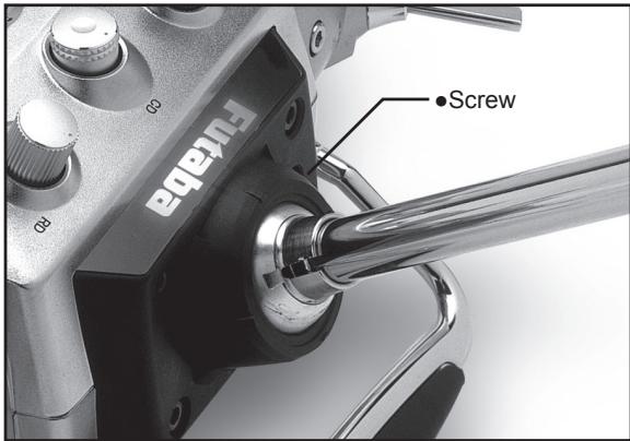
Angle adjustment of the antenna
You can change the angle of the antenna, as you like. Use 2.5mm hexagonal wrench to turn counterclockwise to release the screw on the left of the antenna holder, and change the angle of the antenna, as you like, then retighten.
LED monitor
The color of the FUTABA logo mark shows the status of the transmitter.
(LED Display)
- When you turn on the transmitter, FUTABA logo shows different colors, and then the color stays constantly pink. The FUTABA logo blinks green very rapidly while internal processing is carried out after the power is turned on. Once the internal processing is over, the logo turns to pink color.
-
The FUTABA logo turns on blue when you use DSC cable, or when no is selected for transmit. When the trainer function is set at student's side.
-
The FUTABA logo blinks red slowly when you attach the RF module that is different from the setting.
- Under the normal usage (, that is, radio wave is being emitted), the FUTABA logo turns on green.
Switch reallocation
You can reallocate the toggle switches on the shoulders of the transmitter, as you like.
(Default settings)
SA : 3 positions; Alternate; Short lever
- SB : 3 positions; Alternate; Long lever
- SC : 3 positions; Alternate; Long lever
- SD : 3 positions; Alternate; Short lever
- SE : 3 positions; Alternate: Short lever
SF : 2 positions; Alternate; Long lever
- SG : 2 positions; Alternate; Short lever
- SH : 2 positions; Momentary; Long lever
*You can choose switch and set the ON-direction in the setting screen of the mixing functions.
- When you change switches:
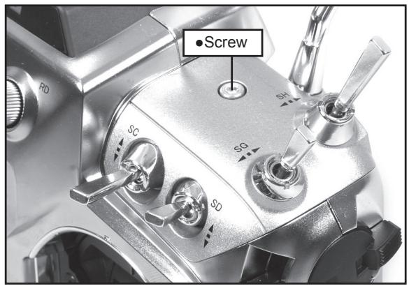
To relocate switches;
- Make sure your transmitter is off, and use the attached 2.5mm hexagonal wrench (inside stylus) to turn the screw counter-clockwise on the switch block and detach the block.
- Disconnect the connectors of switches you want to change.
- Use the attached jig (inside stylus) to turn the face nuts counterclockwise, this will detach the switches.
- To re-attach, use the face nuts to attach switches from other positions or optional switches to the switch block.
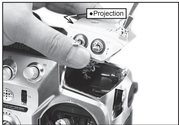
- Connect your connectors.
- Insert the switch block so that it fits correctly into the body of the transmitter (as shown in the picture) and use the hexagonal wrench to tighten the screws.
Volume
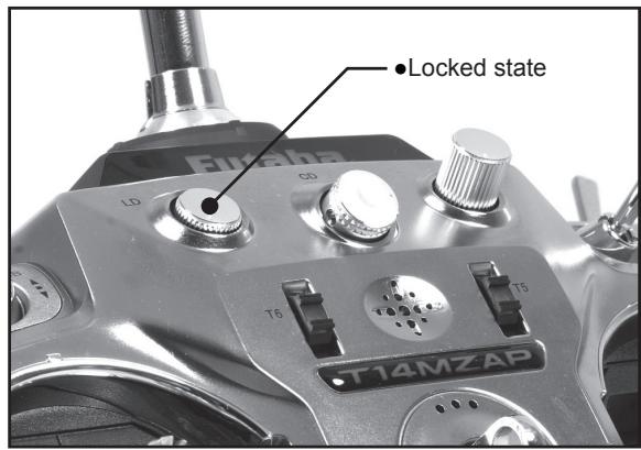
Volume LD, CD, and RD:
If you push the volume to the bottom, the volume will stay there. If you push the volume again, the lock will be released and become operative again.
This volume is digital type (rotary encoder). This volume works as both a volume and a push-switch.
T14MZ beeps when the volume knob reaches center.
You can check the volume position on the Dial Monitor screen in the Linkage menu.
*You can use each setting screen of the mixing functions to select volumes and define the direction of its movement.
Slide Lever
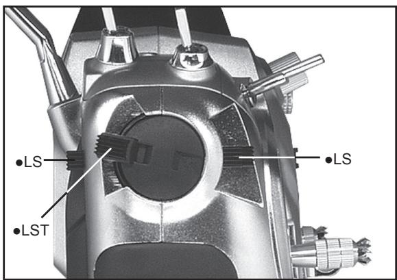
LST (Left), RST (right):
Outside levers
LS (Left), RS (right):
Inside levers: Each lever has two ends, one in front and the other on the back.
It sounds when the lever comes to the center.
You can check the lever position on the dial-monitor screen in the linkage menu.
*You can select a slide lever and set the movement direction on the setting screen of mixing functions.
Digital trim
This transmitter is equipped with digital trims. Each time you press a trim button, the trim position moves one step. If you continue pressing it, the trim position starts to move faster. In addition, when the trim position returns to the center, the tone will change. You can always monitor trim positions by graphics on the screen. To change the trim rate, you must activate this through the function menu, within the linkage menu. Touch the trim button and you will access another screen which enables you to change the trim percentages.
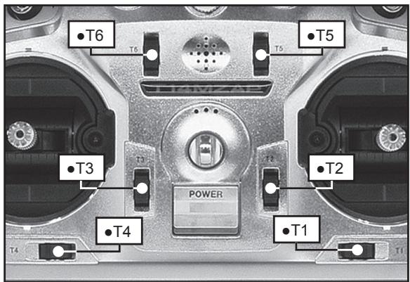
Note: The trim positions you have set will be stored in the non-volatile memory and will remain there.
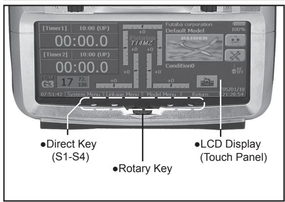
Touch Panel/ Rotary Key/ Direct Key
Touch panel, rotary keys and direct keys are used for entering data.
Touch Panel
Touch the panel with your finger or the attached stylus pen, which is also used as a toolbox, to enter data.
*Plastic film is attached on the glass of the touch panel. Please be careful so that you don't scratch the touch panel with something hard, such as metal and sand sticking on the surface. And don't push the touch panel too hard and don't give any physical shock to the surface. Although you may find some air bubbles under the plastic panel due to environmental changes such as temperature, it is not a defect.
Rotary key
In addition to touch panel, you can select items by rotating the rotary keys to the left or to the right.
Direct key
You can directly call your favorite functions or menu screens.
(The default setting at the factory)
S1: System menu
S2: Linkage menu
S3: Model menu
S4: Return
[How to change assignment of the direct key]
- Open the screen you want to call. Then push S1 and S4 keys simultaneously. (You will see the direct key setting screen.)
- Select the direct key.
Stick Adjustment
Adjustment of the stick lever angle
You can make fine adjustments to the angle of a stick lever either inwards or outwards from the center stick position.
Use the attached 1.5mm hexagonal wrench (inside stylus) to turn the screw clockwise to adjust the stick outwards, or counter-clockwise to tilt it inward.
Note: The screw will fall out if you turn the screw counterclockwise too far.
Adjustment of the lever length
You can adjust the length of stick levers, as you like. It is recommended to adjust the length of the sticks in line with your hand size.
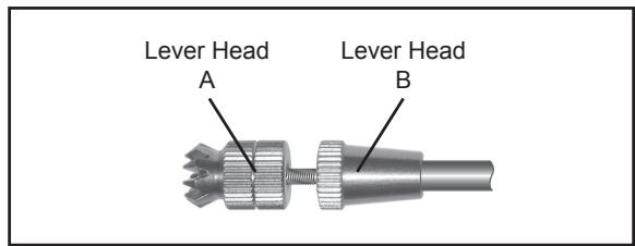
[How to adjust the length]
- Hold the lever head "B" and turn the lever head "A" counter-clockwise, the lock will be released.
- Turn the lever-head "A" clockwise as you hold the lever-head "B" after placing it as you like.
Adjustment of Stick Lever Tension
You can adjust the tension of stick-levers.
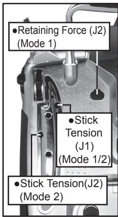
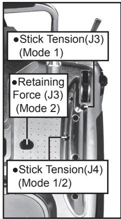
[Adjustment of tension]
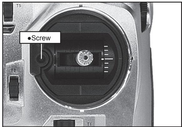
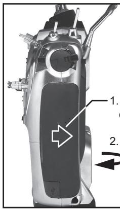
Adjustment of Throttle Stick (Ratchet System)
You can also choose either airplane ratchet system or helicopter-touch.
- Open the dust protection cap on the back of the transmitter that is covering the hole for throttle stick adjustment.
- Use the attached 1.5mm hexagonal wrench (inside stylus) to turn the adjustment screw and set it as you prefer. Turning the screw clockwise increases the tension.
For airplanes: Adjust the screw on the left.
For helicopters: Adjust the screw on the right.
In changing the setting from airplane to helicopter (or heli to airplane);
- Turn the screw counter-clockwise until the throttle stick moves freely, and turn the screw clockwise to adjust it to the tension you prefer.
This transmitter has two ratchet plates, one for airplane and the other one for helicopter. If you tighten both screws, you won't be able to achieve the adjustment that you need because of the overlap of those two adjustments.
If you want to change the setting from airplane to helicopter (or from helicopter to airplane), turn counterclockwise until the throttle stick moves freely. Then turn the screw for the helicopter until you get the tension force you like.
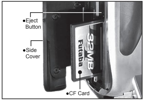
CF Card CFDP32M
CF (Compact Flash) card can store various files, such as model data, music, sound and pictures. Its memory size is 32MB.

Warning
! Be sure to turn off the power to the transmitter before inserting or removing the CF card.
As the CF card is a precision device, do not use excessive force when inserting.
! Be sure to use only Futaba's original CF card, CFDP32M, for the T14MZ transmitter.
- Futaba does not recommend any CF cards other than Futaba's original CF cards.
Set-up of CF card / Removal of CF card
- Turn off the power to the transmitter.
- Slide the card cover on the right side of the transmitter back, and pull open the cover towards you.
- Slide backward the side cover of the transmitter.
-
Then, pull it toward you.
-
Inserting the card: Turn the CF card so that the name seal faces to the back of the transmitter. Then slide the card into the slot until the card touches bottom.
- Press the card cover back and then slide it toward you to close it.
Removal of CF card:
-
Push the eject button and then take out the CF card.
-
Close the card cover and slide it to the original position.
Read data from a PC
Saving music and image files edited by a PC into the CF card, you can use those files on your T14MZ transmitter. Equipment for reading and writing CF cards are available at most electronics stores.
[Important]
Before saving data from the PC, insert the CF card into the transmitter and turn on the power. To save a file from the PC, copy the file to a folder by file type, which are automatically written.
BMP: Picture file WAV: Audio file
WMA: Music file MODEL: Model data
*Use only CF card reader/writer that complies with CFA (CompactFlashTM Association) standard.
Stored data
The life of the CF card is limited due to the use of Flash memory. When you have a problem of saving or reading data such as picture data after a long period of use, please get a new CF card.
We do not have the responsibility of compensating any failure or damage to the data stored in the memory card no matter what the reason is. Be sure to keep the backup of your important data in your CF card.
No necessity for backup; T14MZ transmitters and CF cards are using nonvolatile memory devices so that the data stored in those will not be destroyed even without a backup battery. The clock for the transmitter depends on the Lithium battery.
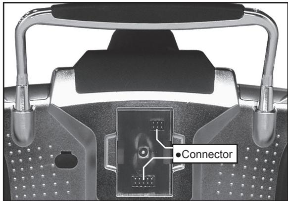
Connector/Plug
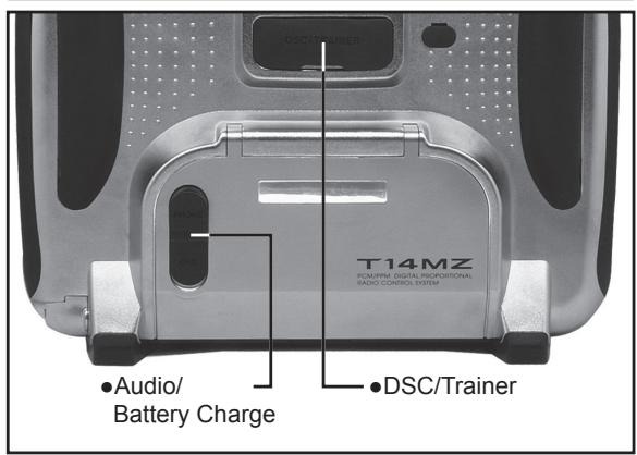
Connector for trainer function (TRAINER)
When you use trainer function, connect the optional trainer cable between the transmitters for teacher and student.
*You can set the trainer function on the Trainer Function screen in the system menu.
Connector for DSC function (DSC)
You can operate the transmitter without transmitting radio waves by connecting the transmitter and the receiver to the DSC cable.
*Please refer to the section "Connection between Receiver/ Servo"
Audio plug (PHONE)
Connecting a stereo headphone to this plug, you can enjoy music files stored in the CF card.
Connector for battery charger (CHG)
This is the connector for charging the Lithium Ion battery LT2F2200 that is installed in the transmitter. Do not use any other chargers except CR-2500 that is for 12V application to charge the LT2F2200 battery through this connector.

Danger
Do not connect any other chargers except CR-2500 to this charging connector.
*If you take out the Lithium Ion battery LT2F2200 from the transmitter, you can use the attached charger LBC-1D5 for charging the battery.
USB port (Transmitter right side)
*This is for factory use only.
Installing and Removing of the battery
LT2F2200 for the transmitter
Attachment of the battery
- Hook one of your fingers in the slit formed by the transmitter's main body and the battery cover on the bottom of the transmitter, and then pull up the cover to release the lock. You can now open the cover in the direction of the arrow.
- Move the slide lever to the right end, and then install the battery in the holder.
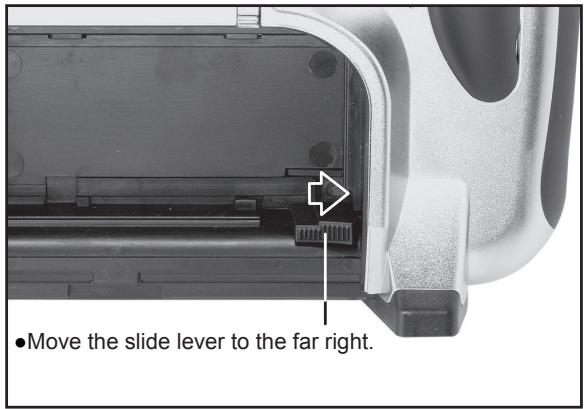
- Push the battery to the left with your finger.

- Close and lock the battery cover until you hear a snapping sound.
Removing of the battery
Note: If you detach the battery while the power is on, the data you have set will not be saved.
- Hook one of your fingers in the slit formed by the transmitter's main body and the battery cover on the back and bottom of the transmitter, and then pull up the cover to release the lock. You can now open the cover in the direction of the arrow.
- Slide the slide lever to the right while pressing it, the battery will be released.
Warning
Be careful to not drop the battery.
Never take out the battery from the T14MZ transmitter while the LED monitor is blinking yellow after turning off the power the T14MZ transmitter.
- Internal devices such as memories may have been destroyed.
- If there is any problem, the message "Backup Error" will be shown the next time when you turn on the power of the transmitter. Do not use the transmitter as it is, send it back for a check to the Futaba Service Center.
RF module MZ-FM
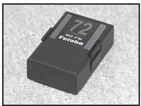
Caution
Be sure to turn off the power of the transmitter before you attach or detach the module.
Detachment of the RF module
Pull the module straight while you are pushing inward the projections on both sides of the module.
*There is a connector above and under the module respectively. So, you might find difficulty in pulling out the module if the module is tilted.
Attachment of the RF module
Insert the module with care so that the connecter pins of the transmitter won't be bent.
Toolbox
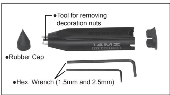
You can use the toolbox contained in the set for various adjustment of the transmitter.
Hexagonal wrench (1.5mm and 2.5mm)
These wrenches are for adjustment of sticks, replacement of the switches and adjustment of the antenna.
Tool for removing decoration nuts
This is for replacement of switches.
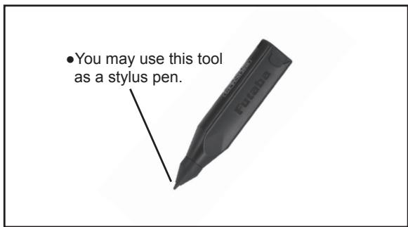
Stylus pen
Rubber cap is attached on the tip of the toolbox. You may use this tool as a stylus pen for operating touch panel. This stylus pen can let you do more precise operation than fingers without damaging the surface.
Receiver nomenclature
Before using the receiver, be sure to read the precautions listed in the following pages.
Receiver R5014DPS
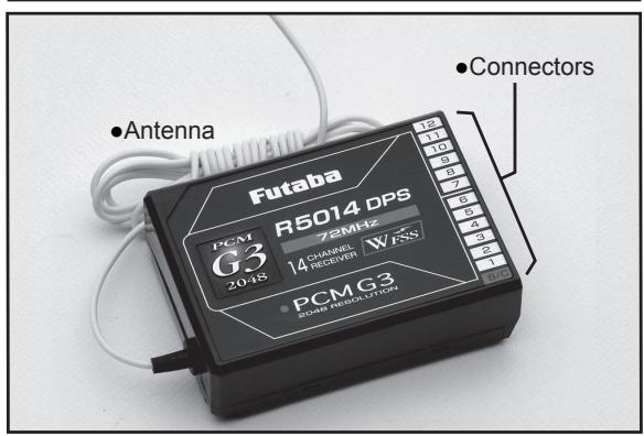
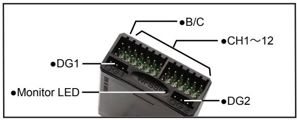
Connector
"1 through 12": outputs for the channels 1 through 12 "DG1", "DG2": outputs of DG1 and DG2 channels "B/C": connector for the power and DSC.
LED Monitor
This monitor is used to check the frequency of the receiver.
Safety precautions when you install receiver and servos
Warning
Connecting connectors
Be sure to insert the connector until it stops at the deepest point.
*If a connecter comes out during the flight due to some reasons such as vibration, your aircraft will crash.
How to protect the receiver from vibration and water
Wrap the receiver with something soft such as foam rubber to avoid vibration. If there is a chance of getting wet, put the receiver in a waterproof bag or balloon to avoid water.
*Strong physical shock or water infiltration may damage the receiver and let the receiver malfunction to crash your aircraft.
Receiver's antenna
Never cut the receiver's antenna. Do not bind the receiver's antenna with the cables for servos.
Locate the receiver's antenna as far as possible from metals such as frames.
*Cutting or binding the receiver's antenna will reduce the radio reception sensitivity and the flight area, causing the crash.
Servos throw
Adjust your system so that pushrods will not bind or sag when operating the servos to the full extent.
*If excessive force is continuously applied to a servo, your aircraft may crash because the servo would be damaged and the battery would be consumed rapidly.
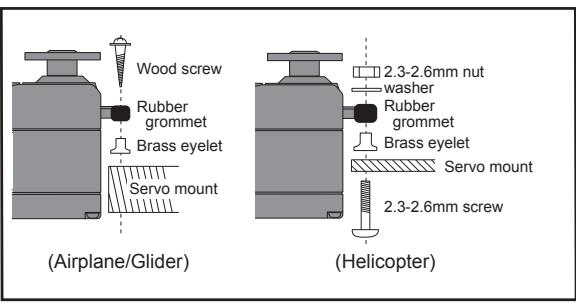
Mounting servos
Use a vibration-proof rubber (such as rubber grommet) under a servo when mounting the servo on a servo mount. And be sure that the servo cases do not touch directly to the metal parts such as servo mount.
*If a servo case is in direct contact with the airframe, the vibration of the airframe directly travels to and may damage the servo.
Internal antenna mounting (Airplanes)

Mounting the power switch
When mounting a power switch to an airframe, make a rectangular hole that is a little larger than the total stroke of the switch so that you can turn ON/OFF without binding.
Avoid mounting the switch where it can be covered by engine oil and dust. In general, it is recommended to mount the power switch on the side of the fuselage that is opposite the muffler.
Battery Charging
Before charging batteries, read the "Cautions for handling battery and battery charger" in the section "For your safety".
How to charge the Lithium Ion battery LT2F2200 for the transmitter
Danger
The Lithium-Ion battery LT2F2200 is only for your T14MZ. Do not use this battery for other equipment.
Be sure to use the battery charger LBC-1D5 to charge the battery.
To charge the battery while installed in the transmitter, use the optional battery charger CR-2500 for 12V.
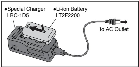
[Method of charging battery]
- Connect the power cable to the charger.
-
Connect the power cable of the charger to the wall socket (AC outlet).
-
The power lamp turns on.
-
Mount the battery and then slide the battery in the direction shown in the figure until you hear a locking sound.
*The charge-lamp turns on and charging starts.
- When the charge-lamp turns off, charging has been completed.
Be sure to remove the power cable from the wall socket after using a battery charger.
It takes about two and a half hours for charging the battery pack that has been used fully. However, the charging time may vary depending on the surrounding air temperature and the condition of the battery pack.
The charge LED blinks (error) if the battery is improperly mounted or the battery itself is a defective product. In this case, remount the battery or use another battery.
If you mount a charged battery, the charge lamp will turn on for several seconds, but it will turn off later.
How to charge the Ni-Cd battery NR4F1500 for the receiver
Use the battery charger FBC-32A that is included in the set.
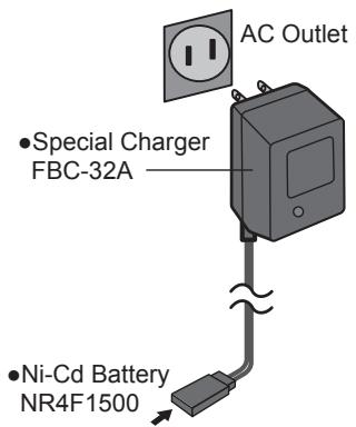
[Method of charging battery]
- Connect the power cable of the charger to the wall socket (AC outlet).
- Connect the connector to the NiCd battery.
*Confirm that the charging indicator, LED lamp, is on.
- Remove the battery after 15 hours.
Battery charging will not automatically stop. Remove the battery from the charger and remove the charger from the wall socket.
It is recommended to reactivate the battery by cycling several times if the battery has not been used for a long period.
*In case of NiCd battery, you may find the poor performance of the battery if you have used the battery only for a short period or if you repeat charging while the battery is not fully discharged. It is recommended to discharge the battery to the recommended level after your usage. It is also recommended to charge the battery just before your usage.
How to turn ON/OFF the power of the transmitter
Windows® CE is installed as a built-in operating system in the T14MZ transmitter. Compared to the conventional system, the T14MZ takes extra time for internal processing when it is turned on/off. For safety reasons, the radio will be emitting only after you push the confirmation button when turning on the power. Please follow the instructions for turning on/off the transmitter.
When turning on the power of the transmitter
- Turn on the power switch of the transmitter.
*After initialization of the transmitter is over, the frequency confirmation screen pops up, and LED monitor turns on pink.
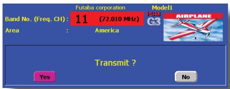
- Check the frequency shown on the screen. If it is OK, then click the button "YES".
LED monitor turns to green and the transmitter begins to emit radio waves.
If you push the button "NO", then the transmitter will not emit radio waves.
Then, you will see the home screen and you will be able to set conditions.
Start-up time; The time required for initializing the internal circuit of the transmitter varies between the previous time you turned off the transmitter and the time you will turned on the power. There are two "start up" modes for your transmitter, see below:
Cold start;
If you turn on the transmitter more than four hours after you last turned it off, the mode is "Cold start". "Cold start" is normal for the first initial power up of the day. It will take about 30 seconds to be ready for use, as it takes time to initialize the internal circuit of the transmitter.
Hot start;
If you turn on the transmitter less than four hours after you last turned it off, the mode is "Hot start". Since initialization has been partly completed, the transmitter will be ready to use in several seconds. "Hot start" takes place usually at a second flight or later flight in the day.
Warning
Once you turn on the power, never shut off the power switch until the power becomes stable (or until the first screen shows up). If you turn off the power switch while the transmitter is going through the initialization process, the data could be damaged. Note: The start-up time may be a little bit slower when the CF card is installed compared to when the card is not.
How to stop the transmitter
Turn off the power switch of the transmitter. The internal circuit of the transmitter starts the shut down process including saving the set-up data. The LED will blink yellow while the transmitter is in the shutdown process.
Once you turn off the power, never operate the power switch until the power shutdown process is fully completed. If you turn on the power switch again while the transmitter is still in the process of power shutdown, the data could be damaged.
As the internal circuit of the transmitter stays on the standby mode for 4 hours after turning off the power, some part of the circuit is consuming current. When you turn on the power during this period, the power starts in "Hot mode". But if more than four hours pass after shutting down the power, the power supply will completely shut down the internal circuit. When you turn on the power after this point, the power starts in "Cold start mode".
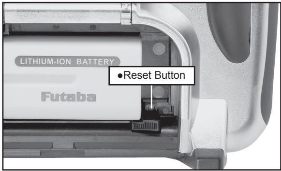
How to reset software
If the screen freezes for some reason and you cannot edit, the transmitter power supply is not shut off even if you turn OFF the power switch. You will need to use the reset button or remove the battery and reinsert it again. In this case, the power restarts in "Cold mode". Even though the screen freezes, all the other functions for radio control operation remain operative.
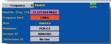
How to change the frequency/How to set ID
The T14MZ system has employed the frequency synthesizer scheme. The T14MZ transmitter will set the frequency of the R5014DPS (PCMG3 receiver) by the wireless data transmission. When you are using a new PCMG3 receiver and changing the frequency, set ID or frequency by the following instructions.
In case of using PCMG3 receivers
*Make sure that PCM-G3 is set as a modulation scheme. Then change the frequency by the following instruction.
How to change the frequency
- Turn on the power of the transmitter.
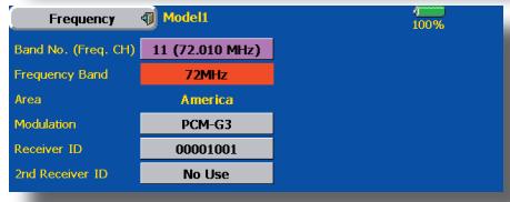
- Push the area that shows the frequency in the home screen or push the "Frequency" button in the Linkage menu. Then the Frequency Set screen will pop up.
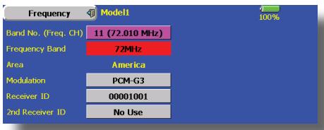
- Push the "Receiver ID" button. Then ID inputting screen for receiver will pop up. Input the eight-digit ID code attached to the receiver's case. Push the "Yes" button after confirming the ID.
Use the "BS" button to move back digit by digit for correction if you made a mistake. If you want to stop changing ID code halfway, push "Return" button to return to the previous screen.
Once you set the ID code for a receiver, you don't have to set the ID code again as long as you change the receiver itself.
When you need to use two receivers for a large size aircraft, you need to enter different ID codes to those receivers respectively.
4. Push the "Band NO. (Frequency)" button if you need to change the frequency. Then you will see frequencies on the screen. Select the frequency you want use. Push the button "Yes" after confirmation. Then you will see the "Confirmation of the change" box.
If you have changed the module prior to turning on the power, confirmation screen will pop up to ask you whether you want to change the frequency. Push the button "Yes" to change the frequency.
5. If the frequency is correct, push the button "Yes". Then you will see the message "Transmitting the frequency data". It takes a certain time to send the new frequency data to the receiver with a sound. (If you need to resend the data, push the "Resend" button.)
6. Turn on the power of the receiver while the
new frequency data is displayed. When the frequency setting for the receiver is completed, the LED monitor of the receiver blinks once and the 1CH servo shuttles three times across the neutral position.
- A very low power, whose frequency is different from that of the channel frequency, is used to set the frequency of the receiver. The reachable distance of the radio is designed to be within several feet. Therefore, put the transmitter and the receiver as close as possible when setting the frequency of the receiver.
- If the receiver can not load the new data due to environmental reasons, connect the transmitter and the receiver directly by the DSC cable. And do the procedure 6 and 7.
*LED monitor will blink on and off if the receiver's ID code is wrong. Then move back to the Receiver ID Set screen and restart the receiver's ID setting from the beginning. - Push the button "End" when the frequency setting is completed. Then turn off the power of the transmitter following the instructions shown on the screen. You will be able to use the new frequency after you turn on the power again.
In case of using PCM1024, PPM receivers
*Make sure that PCM1024 or PPM is set as a modulation scheme. Then change the frequency by the following instruction.
How to change the frequency
- Turn on the power of the transmitter.
- Push the area that shows the frequency in the home screen or push the "Frequency" button in the Linkage menu. Then the Frequency Set screen will pop up.
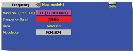
- Push the "Band NO. (Frequency)" button if you need to change the frequency. Then you will see frequencies on the screen. Select the frequency you want use. Push the button "Yes" after confirmation. Then you will see the "Confirmation of the change" box.
*If you have changed the module prior to turning on the power, confirmation screen will pop up to ask you whether you want to change the frequency. Push the button "Yes" to change the frequency. - If the frequency is correct, push the button "Yes". Turn off the power of the transmitter following the instructions shown on the screen. You will be able to use the new frequency after you turn on the power again.
Registration of the user's name
T14MZ transmitter can register user's name.
How to register user's name
- Turn on the power of the transmitter.
- Push the area of the user's name shown on the home screen or the "user's name" in the linkage menu. Then the User's Name Set screen will pop up.
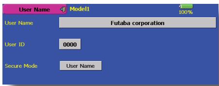
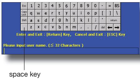
- Push the user's name. Then the keyboard will pop up. You can use up to 32 characters as a user's name. Use the keyboard on the screen to enter user's name.
- Push "Return" key to return to the previous screen after entering the user's name.
(If you want to protect the user's name)
If you don't want anybody else to change your user's name, set your ID in the following way.
*Please be aware that you will not be able to change user's name if you forget your password.
- Make sure that the security mode is "User's name", and then push the User ID button.
- Enter your password, using keyboard on the screen.
You will need to enter your password for changing the user's name from the next time you turn on the power of the transmitter.
*Even if you enter the same character, your password will be identified differently depending on whether you are using "Transform" mode or "Direct" mode for inputting.
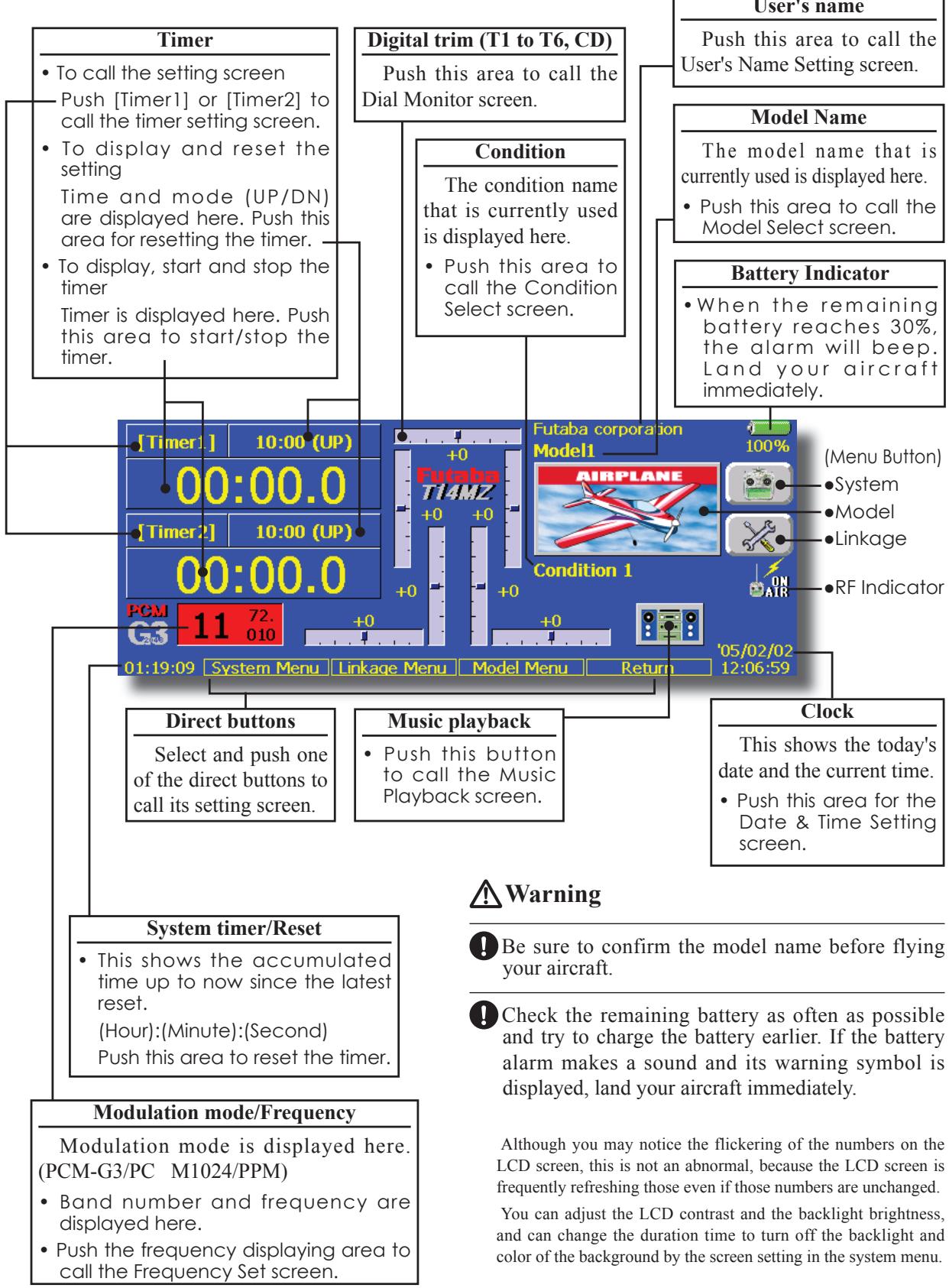
Home screen
Here is the home screen and its descriptions. Use your finger or included stylus pen to operate the touch screen.
Music playback
The T14MZ transmitter can play back the ".wma" music files stored in the CF (Compact Flash) card. You can listen to them through the built-in speaker or a headphone by the earphone plug.
*First, store music files from your PC into the WMA folder on the CF card, and then insert the CF card into your transmitter to play back music files on the transmitter.
[Important notice]
Before downloading files from your PC into the CF card, insert the CF card into the transmitter and turn on the power of the transmitter. Then the following folders will be automatically created in the CF card. When you download files from you PC, copy and paste the files into their corresponding files.
- BMP : picture files
WMA:music files
WAV : sound files -
MODEL : model data files
-
Push the Music Playback button on the home screen to call the following set-up screen.
![FUTABA 14MZ - [Important notice] - 1](/content/2025/01/163546/images/43a799422e2d4f89b2dd34cafe8b7d5c768cbae093177cba50eb6cea719be700.jpg)
To playback
- All the music files saved in the CF card will be shown here.
- Push the file name to select the music file you want to hear.
- Use the buttons on the left to playback or stop the music.
SYSTEM MENU
The System Menu sets up functions of the transmitter, this does not set up any model data.
- When the System Menu button is touched, the menu shown below is called. Call the setup screen by pressing the function you want to set up.
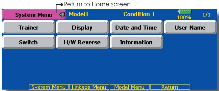
System Menu functions table
[Trainer]: Starts and sets the trainer system.
[Display]: Display adjustment and auto power off setting.
[Date & Time]: Sets the date and time (system clock setting) and resets the timer.
[User Name]: User name registration and ID Pin number.
[Switch]: Toggle switch type setting (Set when the switch is replaced.)
[H/W Reverse]: Reverses the direction of operation of the sticks, switches, trim levers, knobs, etc.
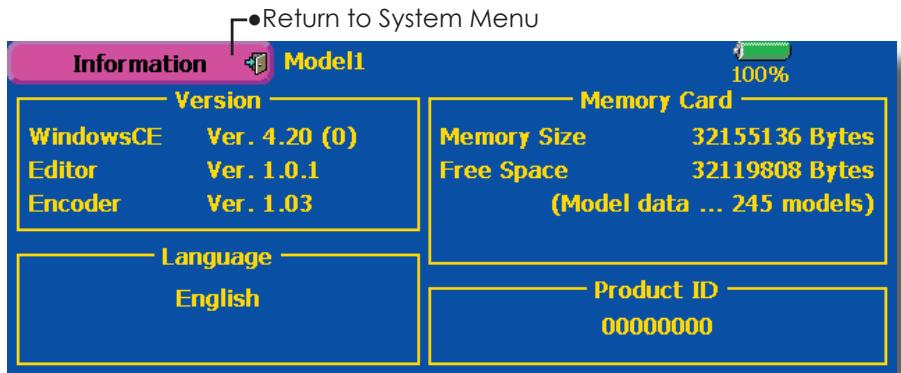
[Information]: Displays the program version, CF card information, and product ID.
The Trainer function makes it possible for the instructor to choose which functions and channels are to be used for instruction, making it possible to match the training ability to the student's skill level. Two transmitters must be connected by an optional Trainer Cord, and the Instructors' transmitter should be programmed for trainer operation, as described below.
When the Instructor activates the trainer switch, the student has control of the aircraft (if MIX or FUNC mode is turned on, the Instructor can make corrections while the student has control). When the switch is released the Instructor regains control. This is very useful if the student gets the aircraft into an undesirable situation.
- Touch the [Trainer] button at the System Menu to call the setup screen shown below.
NOTE: This trainer system can be used in the following manner;
- In the T14MZ transmitter and a conventional transmitter, if the channel order is different. It is necessary to match the channel order in the Linkage Menu when connecting it with other than a T14MZ.
- When the T14MZ is used as the Teacher, set the modulation mode of the student's transmitter to PPM. If being used as the student, set the T14MZ to the modulation mode specified by the Instructors' transmitter. When the Instructors' transmitter is a T14MZ, T9Z, T9C or T7C transmitter, it should be switched to PPM mode.
- Be sure that all channels work correctly in both transmitters before flying.
| Corresponding types of transmitters: |
| T4VF, T6YG, T6YFK, T6X, T6EX, T7U, T7C, T8U, T9C, T9Z, T14MZ |
| Non-corresponding types of transmitters: |
| T6VA, T6DA |
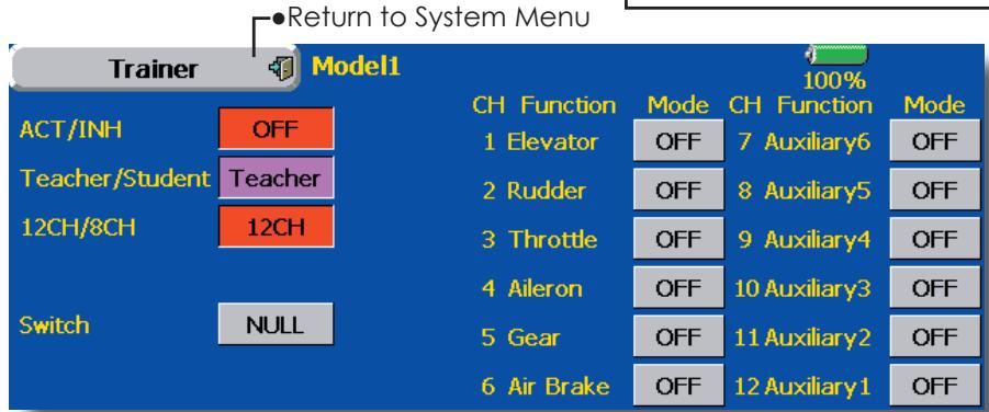
(The display screen is an example. The screen depends on the model type.)
Teacher mode
- Set "Teacher/Student" button to "Teacher".
- Change "ACT/INH" button from "INH" to "OFF" or "ON".
- Set "12CH/8CH" to "12CH" when the student is using T14MZ. Otherwise set it to "8CH".
- Call up the Switch Setting screen by touching "Switch". Then set the desired switch and on/off direction.
- Select the switch mode. If you select "NORM", the trainer function will be turned on or off by a switch position. If you select "ALT", ON and OFF of the trainer function switches alternatively every time the switch is turned on. This means the student side can be operated without holding the switch lever.
- The Instructor side selects the channel for control. Three operating modes are available.
"NORM" mode (Normal mode);
Student side has no control of mixes and settings in Teachers radio..
"MIX" mode;
Student has full advantage of all setting in Teachers radio, plus Teacher has the option to change any setting while Student has control.
"FUNC" mode (Function mode);
Student has control of mixes and rate settings of Teachers radio.
[Notes]
- In the teacher mode, the trainer function display does not come on as long as the student's transmitter is not receiving signals from the teacher's transmitter (when the student's transmitter is not connected).
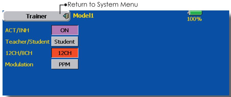
Student mode
- Set "Teacher/Student" button to "Student".
- Change "ACT/INH" button from "INH" to "OFF" or "ON".
- Set "12CH/8CH" to "12CH" when the Instructor is using the T14MZ. Otherwise set it to "8CH".
Note: In "student mode", only the teacher side can turn on and off the power of the student's transmitter. Keep the power switch always at off position. Note: In "teacher mode", the trainer function won't be turned on unless the Instructors' transmitter receives signals from the student's transmitter. Be sure
to confirm this after connecting your trainer cable.
The setup screen for the student mode is shown below.
Display
LCD screen adjustment and auto power off setting
The following LCD screen adjustments and auto power off setting are possible:
- Contrast adjustment
- Auto power off time setting
- Backlighting brightness adjustment
- Background color change
-
Touch panel screen position correction
-
Touch the [Display] button in the System Menu to call the setup screen shown below.
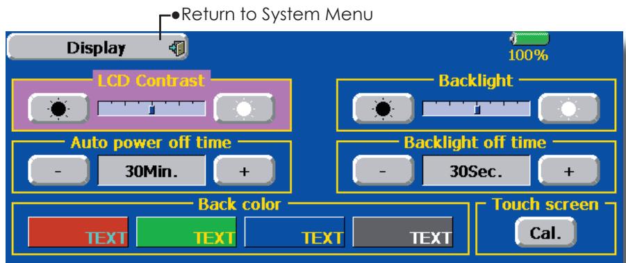
LCD contrast adjustment
- Adjust the LCD contrast with the left and right side buttons.
*When the right side button is pressed, the LCD contrast decreases. When the left side button is pressed, the LCD contrast increases.
Auto power off time setting
- Adjust the auto power off time with the left and right side buttons.
*When the time the transmitter is inactive exceeds the set time, the power is turned off automatically. This time can be set up to 1 hour in 10 minutes increments. The auto power off function can also be deactivated.
Backlighting brightness adjustment
- Adjust the backlighting brightness with the left and right side buttons.
*When the right side button is touched, the backlighting becomes brighter. When the left side button is touched, the backlighting becomes darker.
Backlight power-off time
You can set a time period to turn off the LCD backlight. This function counts the period that the touch panel has been not operated. This time can be set by ten-second steps. You can also turn off the backlight-power-off" if you like.
The backlight consumes a large amount of power. We recommend you to turn off the backlight by setting the backlight power-off time to about one minute.
Since the backlighting power consumption is extremely high, we recommend that the backlighting off time be made short.
Background color
- Touch the button of the color you want to change.
*There are four background colors.
Touch panel calibration
This function adjusts the location of touch panel. Touch "Calibration" button and then press "Yes", the calibration screen will pop up. Touch the center of the cross hair cursor on the screen with the stylus pen. As soon as the system recognizes the position, the cursor will move on to the next position. Repeat this procedure as long as the cursor moves to next position. You will do this five times. Calibration will be carried out based on the five positions. Disappearance of the cross hair cursor means the calibration has been completed. Touch any point on the screen to return to the previous screen.
*In ordinary operation, this calibration is not necessary. If you notice the touch panel is not functioning correctly after long use, we recommend you to carry out this calibration.
Date and Time
Date and time setting (system clock setting) and integrating timer resetting
This function adjusts the system clock of the T14MZ transmitter. Perform this setting when you purchase the set and when adjustment is necessary.
The integrating timer can also be reset.
*The integrating timer is displayed on the Home screen.
- Touch the [Date and Time] button in the System Menu to call the setup screen shown below.
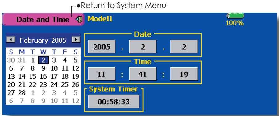
Date setting
- Touch the "Year", "Month", or "Day" button and set the date by touching the [+] or [-] button.
*The date can also be set by pressing the date on the calendar shown at the left.
Time setting
- Touch the "Hour" or "Minute" button, and set the time by touching the [+] or [-] button.
- When the "Second" button is touched, the timer is set to "00" seconds.
Integrating timer reset
The integrating timer shows the total time that has elapsed since the last resetting.
- When the [System Timer] button is touched, the timer is reset.
This function registers the T14MZ user name.
A PIN can also be set to protect the set data or user name.
*Set the PIN carefully. When a system PIN is set, if you forget the PIN, none of the settings can be changed. In this case, the system must be reset by the Futaba Service Center.
- Touch the [UserID] button at the System Menu to call the setup screen shown below.
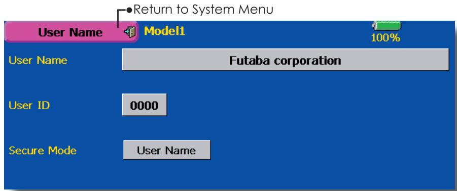
User name registration
- When the User Name box is touched, a keyboard appears on the screen.
- Enter the user name from this keyboard.
A user name of up to 32 characters can be entered.
The set user name is displayed on the Home screen.
(For a detailed description of the input method, see [UserID Registration/Character Input Method] in the Basic Operation section.)
User name or set data protection
- Touch the Security Mode button and select the mode. The mode is switched each time the button is touched.
User Name: Select when you want to protect the user name only.
System: Select when you want to protect all the set data.
-
When the user ID button is touched, a PIN input screen appears. Input a PIN of up to 4 digits.
-
When the "Return" key is touched 2 times, the display returns to the preceding screen.
- When the transmitter power is turned off, the set security mode becomes active.
*When a PIN is set at the user name, it must be entered the next time the User Name screen is opened.
When a System PIN is set, a button displaying a key icon appears on the Home screen.
When you want to change the setting, touch this button and enter the PIN.
If you want to nullify your current password, set the password to "0000" (default value).
Switch
Toggle switch type setting (Setting when the switch was replaced.)
If you modify the location of the switches on the right and left (top) of the transmitter, you should be sure to re-assign functions to the switches for proper operation.
A "Lock" is included to prevent settings from being modified by mistake. When you need to change settings, unlock this by pressing "Lock" it will then read "Unlock" and you can make changes as required.
- Touch the [Switch] button at the System Menu to call the setup screen shown below.
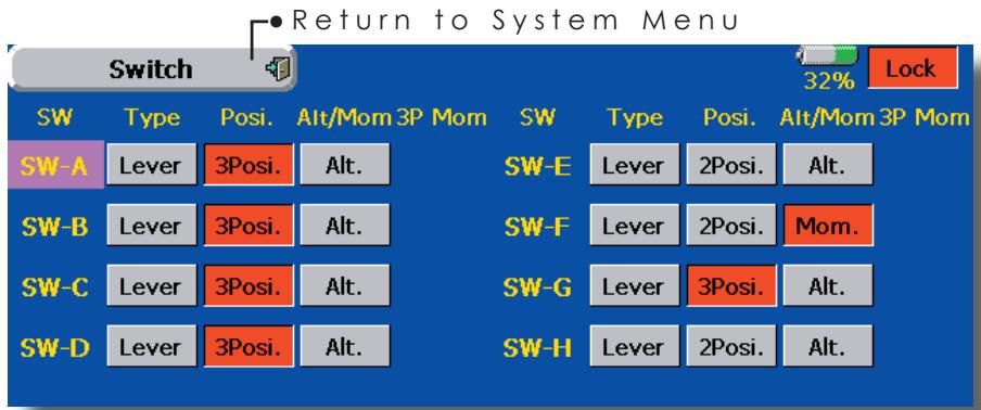
Switch selection
- Select the switch type by touching the [type] button corresponding to the switch to be replaced.
[Lever]: Toggle switch
- Setting for toggle switch is shown above.
2/3 position selection
- Touch the "Posi." button corresponding to the switch and select the position type.
[2 Posi]: 2 position
[3 Posi]: 3 position
[Alt/Mom] mode selection
- Select the operation mode by touching the [Alt/Mom] button corresponding to the switch.
[Alt.]: Alternate type
[Mom.]: Self-return type
- Selection of the [Mom.] mode with a 3-position type switch is shown above.
"3P Mom" mode selection
- Select the operation mode by touching the "3P Mom" button corresponding to the switch.
[Single]: One-side self-return type
[Dual]: Both directions self-return type
This function reverses the operation signal of the sticks, switches, trimmer levers, and knobs.
Note: This setting reverses the actual operation signal, but does not change the display of the indicators on the display. Use the Normal mode as long as there is no special reason to use the Reverse mode.
- Touch the [H/W Reverse] button at the System Menu to call the setup screen shown below.
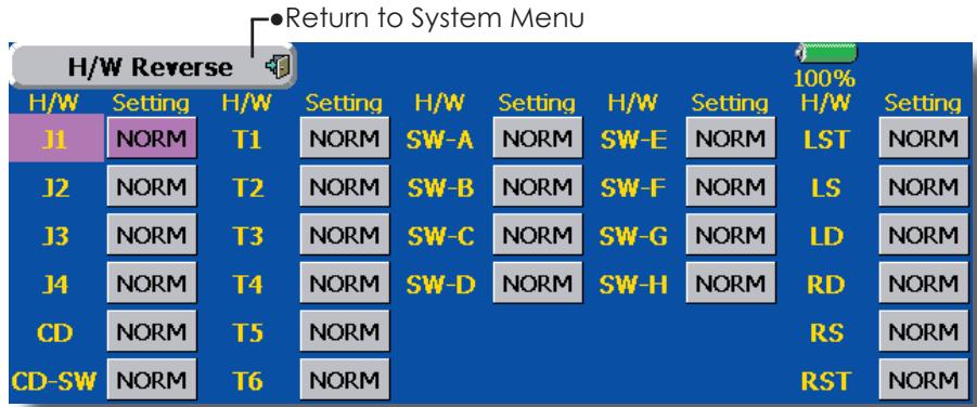
Operation direction reversal method
- Touch the setting button corresponding to the H/W (Hardware) you want to reverse.
- Reverse the H/W by touching [Yes]. (When you want to stop operation, touch [No].) [Normal]: Normal operation direction [Reverse]: Reverses the operation direction.
Information
Displays the program version, CF card information, and product ID.
The T14MZ system program version information, CF card information (memory size, vacant capacity, number of model data, and number of music files), and product ID are displayed on the Information screen.
*When the CF card is not inserted, the CF card information is not displayed.
- Touch the [Information] button at the System Menu to call the setup screen shown below.
Airplane/glider basic setting procedure 1. Model addition and call
Initial setting assigns 1 model to the T14MZ transmitter. The Model Select function of the Linkage Menu is used to add models and to call models which are already set.
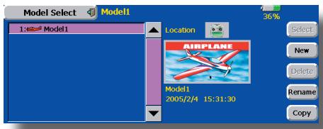
This is convenient when calling a model after its name has been registered. (The data of up to 30 models can be saved to the transmitter. Data can also be saved to the accessory Data-Pack.)
The currently called model name is displayed at the top of the screen. Before flying and before changing any settings, always confirm the model name.
When a new model was added, the Model type select screen and Frequency/Modulation mode/ Receiver ID setup screen automatically appear. After changing or confirming the model, turn the power off and on according to the instructions on the screen. Please be aware that the transmitter will stop transmitting when you change the model.
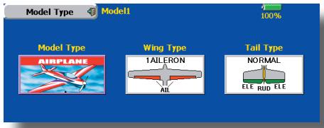
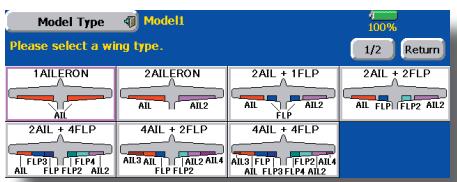
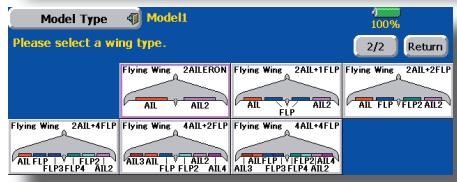
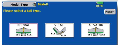
2. Model type selection
Select the model type matched to the fuselage with the Model Type select function of the Linkage Menu. For an airplane, select the model type from among the 3 types: airplane, glider, and motor glider. When the Wing type select screen is displayed and the wing type is selected when selecting the model type, the Tail type select screen is displayed. Select the tail type matched to the fuselage.
There are 13 wing types and 3 tail types for airplane, glider, and motor glider.
3. Fuselage linkage
Link the ailerons, elevators, throttle, rudder, etc. in accordance with the model's instruction manual. For a description of the connection method, see the Receiver and Servos Connection.
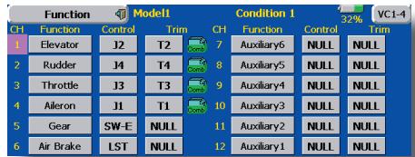
Note: The channel assignment of the T14MZ is different from that of our existing systems. Note that even for the same "airplane model", when the wing type and tail type are different, the channel assignment may be different. (The channel assigned to each function can be checked at the Function menu of the Linkage Menu.)
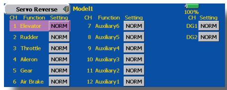
- When the direction of the linkage is reversed, adjust the direction with the Reverse function of the Linkage Menu.
- Connect the throttle linkage so carburetor is open at full trim and full open then the throttle can be cut.
- Adjust the neutral position and rudder angle with the linkage, and fine tune them with the Sub Trim and End Point functions (rudder angle adjustment). To protect the linkage, a limit position can also be set with the End Point function. The End Point function can adjust the amount of up/down and left/right movement, limit, and servo speed of each channel.
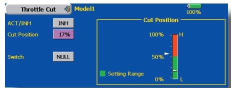
4. Throttle cut setting
Throttle cut can be performed with one touch by a switch without changing the throttle trim position.
Set throttle cut with the Throttle Cut function of the Linkage Menu. After activating the throttle cut function and selecting the switch, adjust the throttle position so that the carburetor becomes full open. For safety, the throttle cut function operates the throttle stick in the 1/3 or less (slow side) position.
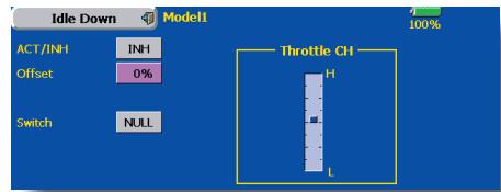
5. Idle down setting
The idling speed can be lowered with one touch by a switch without changing the throttle trim position. Perform this setting with the Idle Down function of the Linkage Menu. After activating the Idle Down function and selecting the switch, adjust the idle down speed. For safety, the idle down function acts only when the throttle stick is in the 1/3 or les (slow side) position.
*While the Throttle Cut function is in operation, the Idle Down function does not work.
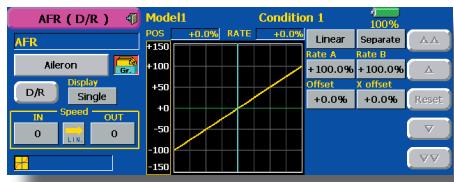
6. AFR (D/R)
AFR function is used to adjust the throw and operation curve of the stick, lever, and switch functions (CH1 to CH12, and V1 to V4) for each flight condition. This is normally used after End Point (ATV) has defined the maximum throw directions (End Point acts on ALL flight condition settings). When mixing is applied from one channel to another channel, both channels can be adjusted at the same time by adjusting the operation rate through the AFR function.
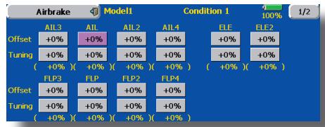
7. Airbrake
This function is used when an air brake is necessary when taking off or diving, etc.
The preset elevators and flaps (camber flap, brake flap) offset amount can be activated by a switch.
The offset amount of the aileron, elevator, and flap servos can be adjusted as needed. Also the speed of the aileron, elevator, and flap servos can be adjusted. (IN side/OUT side) A delay can be set for each condition, and a Cut switch which will turn OFF the delay can be chosen. Trim amounts can be fine-tuned by setting a VR You can also set the Auto Mode, which will link Airbrake to a stick, switch, or dial. A separate stick switch or dial can also be set as the ON/OFF switch.
8. Addition of flight conditions
The transmitter can install up to eight flight conditions per model. You can assign all switches including sticks, switches, trim levers and trim switches as flight-condition selection switches. You can also add delayed mixing to these functions in order to avoid sudden changes. Moreover, you can set priority order for flight conditions when you set more than one condition. In addition, you can copy conditions and/or change names of conditions. This command may also be used to define what switches and/or controls are used to activate each flight condition.
The Condition Select function automatically allocates the Condition 1 for each model type. Condition 1 is the default condition, also referred to as Normal, and is the only one active when a new model type is defined. This condition is always on, and remains on until other conditions are activated by switches.
The Condition Delay can be programmed for each channel. The Condition Delay is used to change the servo throw smoothly when switching conditions.
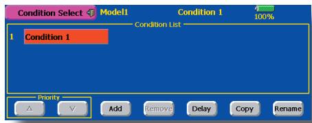
When a new condition is added, "Condition1" data is automatically copied.
Select the condition switch and set the new condition data in the switch ON state. However, if the group mode (Gr.) was selected in advance, the same data will be input at all the conditions. Select the single mode (Sngl) and adjust the condition you want to change.
9. When tailless wing model selected
Tailless wing elevator operation uses elevator camber mixing. This function cannot be performed at initial setting.
Helicopter basic setting procedure
1. Model addition and call
Default setting assigns 1 model to the T14MZ. To add new models or to call a model already set, use the Model Select function of the Linkage Menu.
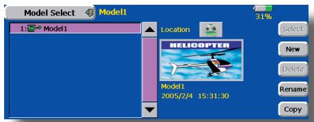
This is convenient when calling a model after registering the model names in advance. (The data of up to 30 models can be saved at the transmitter. Data can also be saved to the accessory Data-Pack.)
The currently called model is displayed at the top of the screen. Before flying and before changing any settings, always confirm the model name.
Please be aware that the transmitter will stop transmitting when you change the model.
When a new model is added, the Model Type Select screen and Frequency/Modulation mode/Receiver ID setup screen automatically appear. Change, or check that they match the type, frequency, and receiver type of the model used.
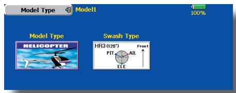
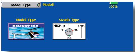
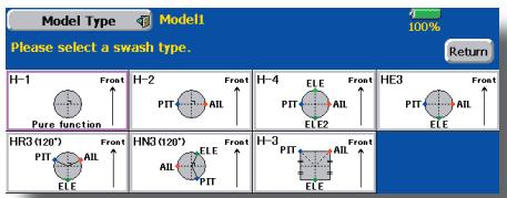
2. Model type and swash type selection
When a separate model type is already selected, select helicopter with the Model Type function of the Linkage Menu, and then select the swash type matched to the fuselage.
3. Flight condition addition
The transmitter can install up to eight flight conditions per model. You can assign all switches including sticks, switches, trim levers and trim switches as flight-condition selection switches. You can also add delayed mixing to these functions in order to avoid sudden changes. Moreover, you can set priority order for flight conditions when you set more than one condition. In addition, you can copy conditions and/or change names of conditions. This command may also be used to define what switches and/or controls are used to activate each flight condition.
The Condition Select function automatically allocates the Condition 0 for each model type. Condition 0 is the default condition, also referred to as Normal, and is the only one active when a new model type is defined. This condition is always on, and remains on until other conditions are activated by switches.
The Condition Delay can be programmed for each channel. The Condition Delay is used to change the servo throw smoothly when switching conditions.

(General flight condition setting example)
- Normal: (Use initial setting conditions/operate when switch OFF)
Use from engine starting to hovering.
- Idle up 1: (Switch setting example: Operate at SW-E center)
Use in 540o stall turn, loop, rolling stall turn, and other maneuvers.
- Idle up 2: (Switch setting example: Operate at SW-E forward side)
Use in rolls.
- Throttle hold: (Switch setting example: Operate at SW-G forward side)
Use in auto rotation.
The priority is throttle hold/idle up 2/idle up 1/ normal. Throttle hold has the highest priority.
Add other conditions, as required.
4. Fuselage linkage
Connect the throttle rudder, ailerons, elevators, pitch, and other rudder linkages in accordance with the kit instruction manual. For a description of the connection method, see "Receiver and Servos Connection".
*The channel assignment of the T14MZ is different from that of our existing systems. (The channel assigned to each function can be checked at the Function menu of the Linkage Menu.)
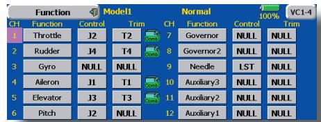
- When the direction of operation of the linkage is reverse, use the Reverse function of the Linkage Menu. Also use the swash AFR function in other than the H-1 mode.
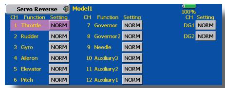
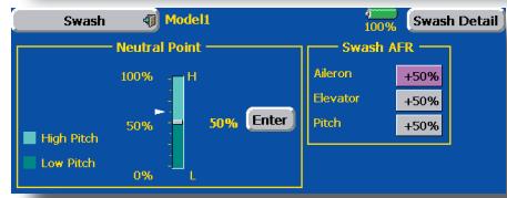
- Adjust the direction of operation of the gyro. (Gyro side function)
- Connect the throttle linkage so that the carburetor becomes full open at full trim throttle cut is possible.
- Basically, adjust the neutral position and rudder angle at the linkage side and fine tune with the Sub-Trim function and End Point function (rudder angle adjustment). To protect the linkage, a limit position can also be set with the End Point function.
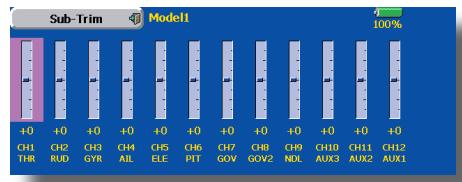
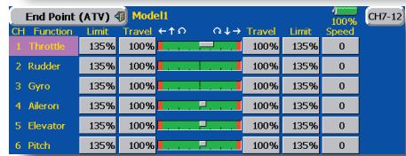
- Swash plate correction (Except H-1 mode) Operation of the swash plate near the hovering point can be corrected by swash AFR function correction mixing. Use this when pitch, aileron, and elevator operation causes the swash plate to deviate from the normal direction.
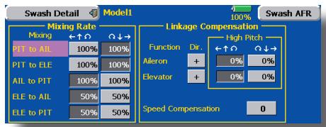
(Call the Swash setup Swash details screen.) Pitch slow side and high side linkage correction is also possible. Adjust so that pitch operation causes the swash plate to move up and down in the horizontal state.
5. Throttle curve setting
This function adjusts the pitch operation curve in relation to the movement of the throttle stick for each condition.
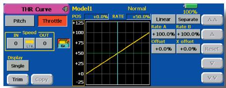
(17 points curve)
The pitch curve can be freely selected from linear operation curve to smooth curve, and adjusted to match the curve you want by means of the T14MZ's powerful Curve Edit Function (6 types of curves can be selected). Up to 17 points can be set for linear or curve types. However, when using the 3 points or 5 points specified to create a curve, a simple and smooth curve can be created by selecting the curve type and reducing the number of input points to 3 or 5, and then entering the specified value at the corresponding points that you created.
Call the throttle curve of each condition with the condition select switch.
- Normal curve adjustment
- Normal curve uses Normal (Linear) type and creates a basic pitch curve centered near hovering. This curve is adjusted together with the Throttle Curve (Normal) so that the engine speed is constant and up/down control is easiest.
- Idle up curve adjustment
- The high side pitch curve sets the maximum pitch regardless of the engine load. The low side pitch curve creates a curve matched for aerobatics (loop, roll, 3D, etc.).
Note: When the curve type is changed, the data is reset.
- Throttle hold curve adjustment
- The throttle hold curve is used when performing auto rotation dives.
Confirm that the rate of the slowest position (0%) of the stick is 0% (initial setting).
Be sure that when set to high side 100% , the curve of any condition does not exceed 100% .
Example of pitch curve setting:
- Call the pitch curve of each condition with the condition select switch.
*Pitch curve graph display can be switched to pitch angle direct reading display.
A. Pitch curve (Normal)
Make the pitch at hovering approximately +5^ 6^ .
Set the pitch at hovering with the stick position at the 50% point as the standard.
*Stability at hovering may be connected to the throttle curve. Adjustment is easy by using the hovering throttle function and hovering pitch function together.
B. Pitch curve (Idle up 1) The idle up 1 pitch curve function creates a curve matched to airborne flight. Set to -7^ + + 12^ as standard.
C. Pitch curve (Idle up 2)
The high side pitch setting is less than idle up 1.
The standard is +8^ .
D. Pitch curve (Hold) At auto rotation, use the maximum pitch at both the high and low sides. [Pitch angle setting example] Throttle hold: -7^ +12^
6. Throttle hold setting
Call the Throttle Hold function from the Model Menu and switch to the throttle hold condition with the condition select switch.
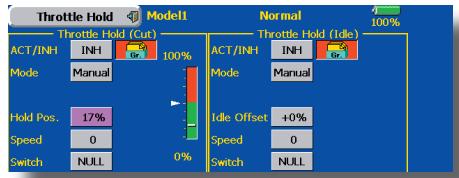
Note: At initial setting, the setting mode is the group mode. Since this function is not used at other conditions, switch to the single mode before setting.
- Setting to the state which activates the function
The throttle hold function allows setting for throttle cut and switching of the function fixed at the idle position by switch for training. Either one or both functions can be performed.
- Hold position setting
- This function sets the servo operation position at throttle hold. (Throttle cut and idle positions)
- Other settings When you want to link operation with stick
The Auto mode can be set. When you want to adjust the servo speed, adjust [Speed].
7. Pitch to RUD mixing setting
Use this function when you want to suppress the torque generated by the changes in the pitch and speed of the main rotor during pitch operation. Adjust it so that the nose does not swing in the rudder direction. However, when using a heading hold gyro like those shown below, do not use Pitch to RUD mixing.
Note: When using a GY601, GY502, GY401, or other heading hold gyro, this Pitch to RUD mixing should not be used. The reaction torque is corrected at the gyro side. When operating the gyro in the AVCS mode, the mixed signal will cause neutral deviation symptoms and the gyro will not operate normally.
Call the Pitch to RUD mixing function from the Model Menu, and set the curve for each condition. (At initial setting, this function is in the "INH" state. To use it, set it to the "ON" state.)
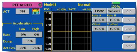
(17 points curve)
Curve setting of up to 17 points is possible. However, in the following setting example, a simple curve can be adjusted by using the [Linear] curve type.
Note: At initial setting, the setting mode is the group mode. In this mode, the same contents are set at in all conditions. When you want to set the selected condition only, switch to the single mode.
Call the mixing curve of each condition with the condition select switch.
- A curve setting example is shown below.
A. Pitch to RUD mixing curve (Normal) Use the hovering system and set this curve to match take off and landing and vertical climb at a constant speed.
*For this curve, use the initial setting [Linear] curve type and adjust the left and right rates in the [Separate] mode.
B. Pitch to RUD mixing (Idle up 1) Use this curve in 540^ stall turn, loop, and rolling stall turn, and adjust it so the fuselage is facing straight ahead when heading into the wind.
*For this curve, [Linear] curve type can be used and the entire curve can be lowered with the [Offset] button.
C. Pitch to RUD mixing (Hold)
This function is set so that the fuselage is facing straight ahead at straight line auto rotation. The pitch of the tail rotor becomes nearly 0^ .
*For this curve, [Linear] curve type can be used and the entire curve can be lowered with the [Offset] button.
- Other settings
The mixing rise characteristic at pitch operation can be adjusted. An acceleration (ACLR) function and deceleration (DCLR) function, which temporarily increase and decrease the mixing amount, can be set.
8. Swash Mix corrects aileron, elevator and pitch interaction
The swash mix function is used to correct the swash plate in the aileron (roll) direction and elevator (cyclic pitch) corresponding to each operation of each condition.
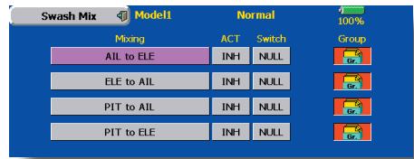
9. Throttle mixing setting
RPM loss caused by swash operation at aileron or elevator operation can be corrected with the Throttle Mix function of the Model Menu. How clockwise and counterclockwise torque is applied when pirouetting can also be corrected.
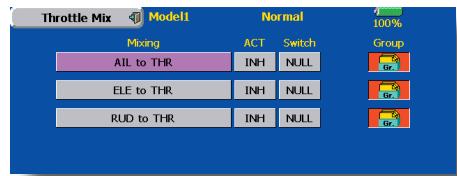
10. Gyro sensitivity and mode switching
The gyro sensitivity and mode switching function is dedicated gyro mixing of the Model Menu, and can be set for each condition.
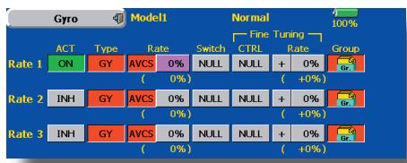
- Normal condition (hovering): Gyro sensitivity maximum
- Idle up 1/Idle up 2/Throttle hold: Gyro sensitivity minimum
However, at auto rotation of a tail-driven helicopter, this function may not have any affect at high gyro sensitivity.
11. Throttle cut setting
Throttle cut provides an easy way to stop the engine, by flipping a switch with the throttle stick at idle. The action is not functional at high throttle to avoid accidental dead sticks. The switch's location and direction must be chosen, as it defaults to NULL.
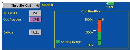
*With throttle stick at idle, adjust the cut position until the engine consistently shuts off, but throttle linkage is not binding. When finished, touch the "Throttle Cut" button to exit.
12. Other special mixings
- Pitch to Needle mixing
- This mixing is used with engines with a construction which allows needle control during flight (fuel-air mixture adjustment). A needle curve can be set. The needle servo rise characteristics at throttle stick acceleration/deceleration operation can be adjusted. (Acceleration function)
- Fuel mixture function
- This mixing is used in needle adjustment of engines which use a fuel mixture control carburetor.
Governor mixing This mixing is dedicated governor mixing when a GV-1 (governor) is used. Up to 3 rates (speeds) can be switched for each condition.
Receiver and servos connection
Connect the receiver and servos in accordance with the connection diagram shown below. Always read [Precautions when mounting the receiver and servos] of [Before using]. When mounting the receiver and servos to the fuselage, connect the necessary points in accordance with the kit instruction manual.
Receiver and servos connection diagram
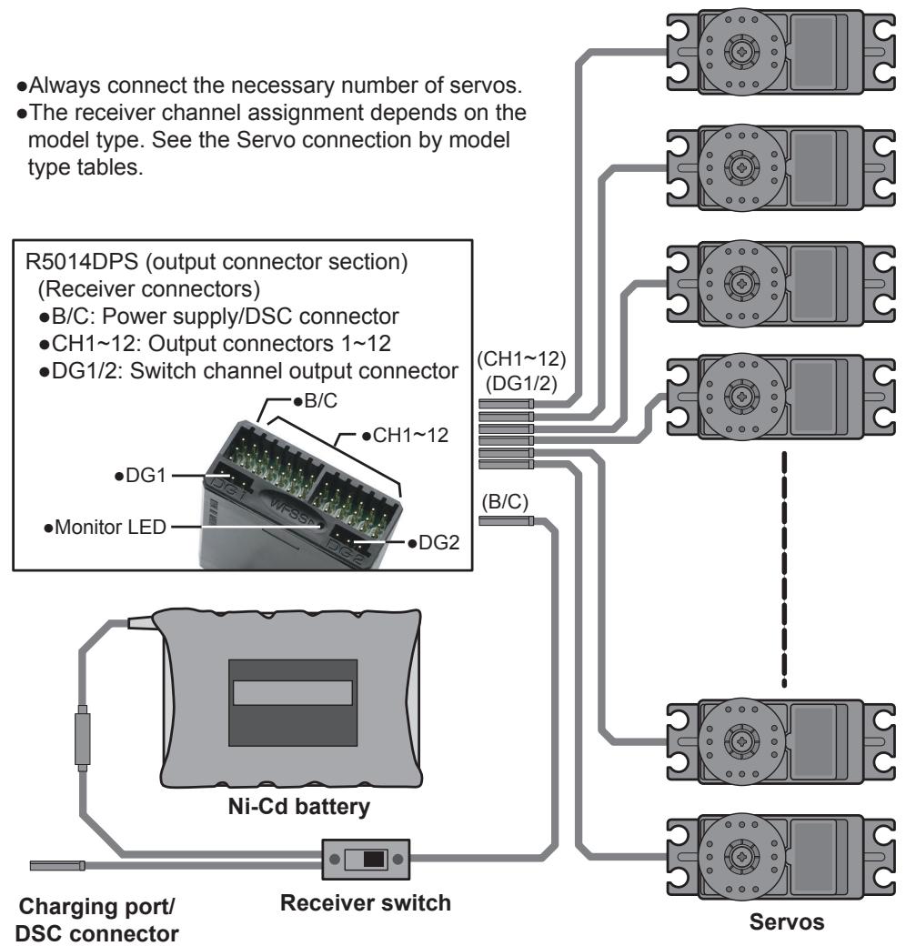
- The Servo connection by model type tables are shown on the following pages. Connect the servos to match the fuselage used.
Servo connection by model type
The T14MZ transmitter channels are automatically assigned for optimal combination according to the type selected with the Model Type function of the Linkage Menu. The channel assignment (initial setting) for each model type is shown below. Connect the receiver and servos to match the type used.
*The set channels can be checked at the Function screen of the Linkage Menu. The channel assignments can also be changed. For more information, read the description of the Function menu.
Airplane/glider/motor glider
Airplane and V tail
| RX CH | 1AIL | 2AIL | 2AIL+1FLAP | 2AIL+2FLAP | ||||||||
| Airplane | Glider | Airplane | Glider | Airplane | Glider | Airplane | Glider | |||||
| EP | EP | EP | EP | |||||||||
| 1 | Elevator | Elevator | Elevator | Elevator | Elevator | Elevator | Elevator | Elevator | Elevator | Elevator | Elevator | Elevator |
| 2 | Rudder | Rudder | Rudder | Rudder | Rudder | Rudder | Rudder | Rudder | Rudder | Rudder | Rudder | Rudder |
| 3 | Throttle | Motor | AUX1 | Throttle | Motor | AUX1 | Throttle | Motor | AUX7 | Throttle | Motor | AUX6 |
| 4 | Aileron | Aileron | Aileron | Aileron | Aileron | Aileron | Aileron | Aileron | Aileron | Aileron | Aileron | Aileron |
| 5 | Gear | AUX7 | AUX7 | Aileron2 | Aileron2 | Aileron2 | Aileron2 | Aileron2 | Aileron2 | Aileron2 | Aileron2 | Aileron2 |
| 6 | Airbrake | Airbrake | Airbrake | Gear | AUX7 | AUX7 | Flap | Flap | Flap | Gear | AUX5 | AUX5 |
| 7 | AUX6 | AUX6 | AUX6 | AUX6 | AUX6 | AUX6 | Gear | AUX6 | AUX6 | Flap | Flap | Flap |
| 8 | AUX5 | AUX5 | AUX5 | AUX5 | AUX5 | AUX5 | AUX5 | AUX5 | AUX5 | Flap2 | Flap2 | Flap2 |
| 9 | AUX4 | AUX4 | AUX4 | AUX4 | AUX4 | AUX4 | AUX4 | AUX4 | AUX4 | AUX4 | AUX4 | AUX4 |
| 10 | AUX3 | AUX3 | AUX3 | AUX3 | AUX3 | AUX3 | AUX3 | AUX3 | AUX3 | AUX3 | AUX3 | AUX3 |
| 11 | AUX2 | AUX2 | AUX2 | AUX2 | AUX2 | AUX2 | AUX2 | AUX2 | AUX2 | AUX2 | AUX2 | AUX2 |
| 12 | AUX1 | AUX1 | AUX1 | AUX1 | AUX1 | AUX1 | AUX1 | AUX1 | AUX1 | AUX1 | AUX1 | AUX1 |
| VC1 | AUX1 | AUX1 | AUX1 | Camber | Camber | Camber | Camber | Camber | Camber | Camber | Camber | Camber |
| VC2 | AUX1 | AUX1 | AUX1 | AUX1 | Butterfly | Butterfly | AUX1 | Butterfly | Butterfly | AUX1 | Butterfly | Butterfly |
| VC3 | AUX1 | AUX1 | AUX1 | AUX1 | AUX1 | AUX1 | AUX1 | AUX1 | AUX1 | AUX1 | AUX1 | AUX1 |
| VC4 | AUX1 | AUX1 | AUX1 | AUX1 | AUX1 | AUX1 | AUX1 | AUX1 | AUX1 | AUX1 | AUX1 | AUX1 |
- When a receiver other than the PCM-G3 type is used, only the shaded part of the table above is valid.
- VC1~4 are vertical channels without receiver output. For more information, see the description of the Function menu of the Linkage Menu.
| RX CH | 2AIL+4FLAP | 4AIL+2FLAP | 4AIL+4FLAP | ||||||
| Airplane | Glider | Airplane | Glider | Airplane | Glider | ||||
| EP | EP | EP | |||||||
| 1 | Elevator | Elevator | Elevator | Elevator | Elevator | Elevator | Elevator | Elevator | Elevator |
| 2 | Rudder | Rudder | Rudder | Rudder | Rudder | Rudder | Rudder | Rudder | Rudder |
| 3 | Throttle | Motor | AUX4 | Throttle | Motor | AUX4 | Throttle | Motor | AUX2 |
| 4 | Aileron | Aileron | Aileron | Aileron | Aileron | Aileron | Aileron | Aileron | Aileron |
| 5 | Aileron2 | Aileron2 | Aileron2 | Aileron2 | Aileron2 | Aileron2 | Aileron2 | Aileron2 | Aileron2 |
| 6 | Gear | AUX3 | AUX3 | Gear | AUX3 | AUX3 | Gear | AUX1 | AUX1 |
| 7 | Flap | Flap | Flap | Aileron3 | Aileron3 | Aileron3 | Aileron3 | Aileron3 | Aileron3 |
| 8 | Flap2 | Flap2 | Flap2 | Aileron4 | Aileron4 | Aileron4 | Aileron4 | Aileron4 | Aileron4 |
| 9 | Flap3 | Flap3 | Flap3 | Flap1 | Flap1 | Flap1 | Flap1 | Flap1 | Flap1 |
| 10 | Flap4 | Flap4 | Flap4 | Flap2 | Flap2 | Flap2 | Flap2 | Flap2 | Flap2 |
| 11 | AUX2 | AUX2 | AUX2 | AUX2 | AUX2 | AUX2 | Flap3 | Flap3 | Flap3 |
| 12 | AUX1 | AUX1 | AUX1 | AUX1 | AUX1 | AUX1 | Flap4 | Flap4 | Flap4 |
| VC1 | Camber | Camber | Camber | Camber | Camber | Camber | Camber | Camber | Camber |
| VC2 | AUX1 | Butterfly | Butterfly | AUX1 | Butterfly | Butterfly | AUX1 | Butterfly | Butterfly |
| VC3 | AUX1 | AUX1 | AUX1 | AUX1 | AUX1 | AUX1 | AUX1 | AUX1 | AUX1 |
| VC4 | AUX1 | AUX1 | AUX1 | AUX1 | AUX1 | AUX1 | AUX1 | AUX1 | AUX1 |
Ailevator
| RX CH | 1AIL | 2AIL | 2AIL+1FLAP | 2AIL+2FLAP | ||||||||
| Airplane | Glider | Airplane | Glider | Airplane | Glider | Airplane | Glider | |||||
| EP | EP | EP | EP | |||||||||
| 1 | Elevator | Elevator | Elevator | Elevator | Elevator | Elevator | Elevator | Elevator | Elevator | Elevator | Elevator | Elevator |
| 2 | Elevator2 | Elevator2 | Elevator2 | Elevator2 | Elevator2 | Elevator2 | Elevator2 | Elevator2 | Elevator2 | Elevator2 | Elevator2 | Elevator2 |
| 3 | Rudder | Rudder | Rudder | Rudder | Rudder | Rudder | Rudder | Rudder | Rudder | Rudder | Rudder | Rudder |
| 4 | Aileron | Aileron | Aileron | Aileron | Aileron | Aileron | Aileron | Aileron | Aileron | Aileron | Aileron | Aileron |
| 5 | Throttle | Motor | AUX7 | Aileron2 | Aileron2 | Aileron2 | Aileron2 | Aileron2 | Aileron2 | Aileron2 | Aileron2 | Aileron2 |
| 6 | Airbrake | Airbrake | Airbrake | Throttle | Motor | AUX7 | Throttle | Motor | AUX6 | Throttle | Motor | AUX5 |
| 7 | Gear | AUX6 | AUX6 | Gear | AUX6 | AUX6 | Flap | Flap | Flap | Flap | Flap | Flap |
| 8 | AUX5 | AUX5 | AUX5 | AUX5 | AUX5 | AUX5 | Gear | AUX5 | AUX5 | Flap2 | Flap2 | Flap2 |
| 9 | AUX4 | AUX4 | AUX4 | AUX4 | AUX4 | AUX4 | AUX4 | AUX4 | AUX4 | Gear | AUX4 | AUX4 |
| 10 | AUX3 | AUX3 | AUX3 | AUX3 | AUX3 | AUX3 | AUX3 | AUX3 | AUX3 | AUX3 | AUX3 | AUX3 |
| 11 | AUX2 | AUX2 | AUX2 | AUX2 | AUX2 | AUX2 | AUX2 | AUX2 | AUX2 | AUX2 | AUX2 | AUX2 |
| 12 | AUX1 | AUX1 | AUX1 | AUX1 | AUX1 | AUX1 | AUX1 | AUX1 | AUX1 | AUX1 | AUX1 | AUX1 |
| VC1 | AUX1 | AUX1 | AUX1 | Camber | Camber | Camber | Camber | Camber | Camber | Camber | Camber | Camber |
| VC2 | AUX1 | AUX1 | AUX1 | AUX1 | Butterfly | Butterfly | AUX1 | Butterfly | Butterfly | AUX1 | Butterfly | Butterfly |
| VC3 | AUX1 | AUX1 | AUX1 | AUX1 | AUX1 | AUX1 | AUX1 | AUX1 | AUX1 | AUX1 | AUX1 | AUX1 |
| VC4 | AUX1 | AUX1 | AUX1 | AUX1 | AUX1 | AUX1 | AUX1 | AUX1 | AUX1 | AUX1 | AUX1 | AUX1 |
- When a receiver other than the PCM-G3 type is used, only the shaded part of the table above is valid.
- VC1~4 are vertical channels without a receiver output. For more information, see the description of the Function menu of the Linkage Menu.
| RX CH | 2AIL+4FLAP | 4AIL+2FLAP | 4AIL+4FLAP | ||||||
| Airplane | Glider | Airplane | Glider | Airplane | Glider | ||||
| EP | EP | EP | |||||||
| 1 | Elevator | Elevator | Elevator | Elevator | Elevator | Elevator | Elevator | Elevator | Elevator |
| 2 | Elevator2 | Elevator2 | Elevator2 | Elevator2 | Elevator2 | Elevator2 | Elevator2 | Elevator2 | Elevator2 |
| 3 | Rudder | Rudder | Rudder | Rudder | Rudder | Rudder | Rudder | Rudder | Rudder |
| 4 | Aileron | Aileron | Aileron | Aileron | Aileron | Aileron | Aileron | Aileron | Aileron |
| 5 | Aileron2 | Aileron2 | Aileron2 | Aileron2 | Aileron2 | Aileron2 | Aileron2 | Aileron2 | Aileron2 |
| 6 | Throttle | Motor | AUX7 | Throttle | Motor | AUX3 | Throttle | Motor | AUX1 |
| 7 | Flap | Flap | Flap | Aileron3 | Aileron3 | Aileron3 | Aileron3 | Aileron3 | Aileron3 |
| 8 | Flap2 | Flap2 | Flap2 | Aileron4 | Aileron4 | Aileron4 | Aileron4 | Aileron4 | Aileron4 |
| 9 | Flap3 | Flap3 | Flap3 | Flap1 | Flap1 | Flap1 | Flap1 | Flap1 | Flap1 |
| 10 | Flap4 | Flap4 | Flap4 | Flap2 | Flap2 | Flap2 | Flap2 | Flap2 | Flap2 |
| 11 | Gear | AUX2 | AUX2 | Gear | AUX2 | AUX2 | Flap3 | Flap3 | Flap3 |
| 12 | AUX1 | AUX1 | AUX1 | AUX1 | AUX1 | AUX1 | Flap4 | Flap4 | Flap4 |
| VC1 | Camber | Camber | Camber | Camber | Camber | Camber | Camber | Camber | Camber |
| VC2 | AUX1 | Butterfly | Butterfly | AUX1 | Butterfly | Butterfly | AUX1 | Butterfly | Butterfly |
| VC3 | AUX1 | AUX1 | AUX1 | AUX1 | AUX1 | AUX1 | AUX1 | AUX1 | AUX1 |
| VC4 | AUX1 | AUX1 | AUX1 | AUX1 | AUX1 | AUX1 | AUX1 | AUX1 | AUX1 |
- Tailless wing
| RX CH | 2AIL | 2AIL+1FLAP | 2AIL+2FLAP | ||||||
| Airplane | Glider | Airplane | Glider | Airplane | Glider | ||||
| EP | EP | EP | |||||||
| 1 | Rudder | Rudder | Rudder | Rudder | Rudder | Rudder | Rudder | Rudder | Rudder |
| 2 | Rudder2 | Rudder2 | Rudder2 | Rudder2 | Rudder2 | Rudder2 | Rudder2 | Rudder2 | Rudder2 |
| 3 | Throttle | Motor | AUX1 | Throttle | Motor | AUX7 | Throttle | Motor | AUX6 |
| 4 | Aileron | Aileron | Aileron | Aileron | Aileron | Aileron | Aileron | Aileron | Aileron |
| 5 | Aileron2 | Aileron2 | Aileron2 | Aileron2 | Aileron2 | Aileron2 | Aileron2 | Aileron2 | Aileron2 |
| 6 | Gear | AUX7 | AUX7 | Flap | Flap | Flap | Gear | AUX5 | AUX5 |
| 7 | AUX6 | AUX6 | AUX6 | Gear | AUX6 | AUX6 | Flap | Flap | Flap |
| 8 | AUX5 | AUX5 | AUX5 | AUX5 | AUX5 | AUX5 | Flap2 | Flap2 | Flap2 |
| 9 | AUX4 | AUX4 | AUX4 | AUX4 | AUX4 | AUX4 | AUX4 | AUX4 | AUX4 |
| 10 | AUX3 | AUX3 | AUX3 | AUX3 | AUX3 | AUX3 | AUX3 | AUX3 | AUX3 |
| 11 | AUX2 | AUX2 | AUX2 | AUX2 | AUX2 | AUX2 | AUX2 | AUX2 | AUX2 |
| 12 | AUX1 | AUX1 | AUX1 | AUX1 | AUX1 | AUX1 | AUX1 | AUX1 | AUX1 |
| VC1 | Elevator | Elevator | Elevator | Elevator | Elevator | Elevator | Elevator | Elevator | Elevator |
| VC2 | AUX1 | AUX1 | AUX1 | Camber | Camber | Camber | Camber | Camber | Camber |
| VC3 | AUX1 | AUX1 | AUX1 | AUX1 | Butterfly | Butterfly | AUX1 | Butterfly | Butterfly |
| VC4 | AUX1 | AUX1 | AUX1 | AUX1 | AUX1 | AUX1 | AUX1 | AUX1 | AUX1 |
- When a receiver other than the PCM-G3 type is used, only the shaded part of the table above is valid.
- VC1~4 are virtual channels without a receiver output. For more information, see the description of the Function menu of the Linkage Menu.
| RX CH | 2AIL+4FLAP | 4AIL+2FLAP | 4AIL+4FLAP | ||||||
| Airplane | Glider | Airplane | Glider | Airplane | Glider | ||||
| EP | EP | EP | |||||||
| 1 | Rudder | Rudder | Rudder | Rudder | Rudder | Rudder | Rudder | Rudder | Rudder |
| 2 | Rudder2 | Rudder2 | Rudder2 | Rudder2 | Rudder2 | Rudder2 | Rudder2 | Rudder2 | Rudder2 |
| 3 | Throttle | Motor | AUX4 | Throttle | Motor | AUX4 | Throttle | Motor | AUX2 |
| 4 | Aileron | Aileron | Aileron | Aileron | Aileron | Aileron | Aileron | Aileron | Aileron |
| 5 | Aileron2 | Aileron2 | Aileron2 | Aileron2 | Aileron2 | Aileron2 | Aileron2 | Aileron2 | Aileron2 |
| 6 | Gear | AUX3 | AUX3 | Gear | AUX3 | AUX3 | Gear | AUX1 | AUX1 |
| 7 | Flap | Flap | Flap | Aileron3 | Aileron3 | Aileron3 | Aileron3 | Aileron3 | Aileron3 |
| 8 | Flap2 | Flap2 | Flap2 | Aileron4 | Aileron4 | Aileron4 | Aileron4 | Aileron4 | Aileron4 |
| 9 | Flap3 | Flap3 | Flap3 | Flap1 | Flap1 | Flap1 | Flap1 | Flap1 | Flap1 |
| 10 | Flap4 | Flap4 | Flap4 | Flap2 | Flap2 | Flap2 | Flap2 | Flap2 | Flap2 |
| 11 | AUX2 | AUX2 | AUX2 | AUX2 | AUX2 | AUX2 | Flap3 | Flap3 | Flap3 |
| 12 | AUX1 | AUX1 | AUX1 | AUX1 | AUX1 | AUX1 | Flap4 | Flap4 | Flap4 |
| VC1 | Elevator | Elevator | Elevator | Elevator | Elevator | Elevator | Elevator | Elevator | Elevator |
| VC2 | Camber | Camber | Camber | Camber | Camber | Camber | Camber | Camber | Camber |
| VC3 | AUX1 | Butterfly | Butterfly | AUX1 | Butterfly | Butterfly | AUX1 | Butterfly | Butterfly |
| VC4 | AUX1 | AUX1 | AUX1 | AUX1 | AUX1 | AUX1 | AUX1 | AUX1 | AUX1 |
Helicopter
| CH | H-4 Swash | All Other |
| 1 | Throttle | Throttle |
| 2 | Rudder | Rudder |
| 3 | Aileron | Gyro |
| 4 | Elevator 1 | Aileron |
| 5 | Pitch | Elevator |
| 6 | Elevator 2 | Pitch |
| 7 | Gyro | Governor 1 |
| 8 | Governor 1 | Governor 2 |
| 9 | Governor 2 | Needle |
| 10 | Needle | AUX3 |
| 11 | AUX2 | AUX2 |
| 12 | AUX1 | AUX1 |
| VC1 | AUX1 | AUX1 |
| VC2 | AUX1 | AUX1 |
| VC3 | AUX1 | AUX1 |
| VC4 | AUX1 | AUX1 |
- When a receiver other than the PCM-G3 type is used, only the shaded part of the table at the left is valid.
- VC1~4 are virtual channels with no receiver output. For more information, see the description of the Function menu of the Linkage Menu.
FUNCTIONS OF LINKAGE MENU
The Linkage Menu is made up of functions which perform model addition, model type selection, frequency setting, end point setting, and other model basic settings.
The functions which can be selected depend on the model type. A typical menu screen is shown below.
- When a button in the Linkage Menu of the Home screen is touched, the menu shown below is called. Touch the button of the function you want to set.
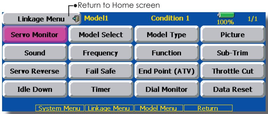
(The display screen is an example. The screen depends on the model type.)
Linkage Menu functions table
[Servo Monitor]: Displays the servo test and operation position
[Model Select]: Model addition, call, deletion, copy, model name setting
[Model Type]: Model type, wing type, switch type, etc. selection
[Picture]: Picture paste for each model
[Sound]: Sound recording and playback
[Frequency]: Frequency selection, modulation mode selection, receiver ID setting
[Function]: Channel assignment of each function can be changed
[Sub-Trim]: Adjusts the neutral position of each servo
[Servo Reverse]: Servo direction reversal
[Fail Safe]: Fail safe function and battery fail safe function setting
[End Point (ATV)]: Servo basic rudder adjustment and limit setting
[Throttle Cut]: Stops the engine safely and easily (airplane and helicopter only)
[Idle Down]: Lowers the idle speed of the engine (airplane and helicopter only)
[Swash]: Swash AFR and linkage correction function (helicopter only)
[Timer]: Timer setting and lap time display
[Dial Monitor]: Dial, sliding lever, and digital trim position display
[Data Reset]: Model memory set data reset (by item)
Servo Monitor
Servo Test & Graph Display / Displays servo positions.
This is used for testing servo movement. Touch "Moving Test" (repetition mode) or "Neutral Test" (fixed position mode) depending on which one shows on the screen. To get from one to the other, simply touch the field again, and you will
move from "Moving Test" to "Neutral Test" automatically. Next touch the "Test" on/off button to start testing your servos. The "Neutral test" is good for finding the neutral position of a servo horn.
- Touch the [Servo Monitor] button in the Linkage Menu to call the setup screen shown below.
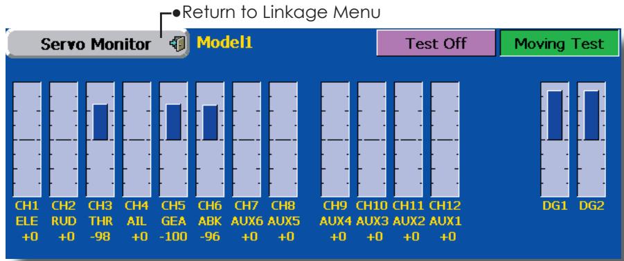
Servo test operation
- Select a test mode ([Moving] or [Neutral]). [Repeat]: Each servo repeats operation. [Neutral]: Each servo is locked in the neutral position.
- When the [Test Off] button is touched, testing begins in the selected mode.
Model Select
The Model Selection function performs model addition, call, deletion, copy, and model name setting.
This function is used to load the settings of the desired model into the T14MZ's memory.
The settings may be selected from either the transmitter's built-in memory or a Data-Pack CFDP32M (Compact Flash card; 32MB). Remember that up to 30 model memories are available in the transmitter; these may be stored in the CFDP32M card.
The name of the model stored in the transmitter and the Data-Pack may be changed. This can be very useful to tell different models settings apart. Each model name
can be as long as 32 characters, and the model name always appears in the display screen.
The Copy function is used to copy one set of model data into a second memory within the transmitter and the Data-Pack. It may be used for getting a head-start on setting up models with almost the same settings (only differences need to be modified, instead of entering the complete model from scratch). Also, this function may be used to make a backup copy of a model setup before any changes are made.
- Touch the [Model Select] button in the Linkage Menu to call the setup screen shown below.
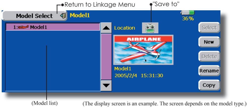
Model call
- Touch the "Save to" icon, and select the location to which the desired model is to be saved.
Transmitter icon: Transmitter memory
Data pack icon: CF card - Touch the desired model in the model list.
- Touch the [Select] button.
- Touch [Yes] to call the model. (When you want to cancel model call, press [No].)
Model addition
- Touch the [New] button.
- Touch [Yes] to add the model. (When you want to cancel model addition, touch [No].)
*When a new model is added, the Model Type screen and Frequency screen are automatically displayed. Check or change the model and frequency. If there are no changes, touch the Model Type and Frequency icons.
*The added model is displayed in the model list.
Model deletion
- Touch the "Save to" icon or the model you want to delete in the model list. (The model currently selected cannot be deleted.)
- Touch the [Delete] button.
- Touch [Yes]. (When you want to stop model deletion, touch [No].)
Model name change
- Select the model by touching the "Save to" icon or the desired model in the model list.
- When [Change Name] is touched, a keyboard appears on the screen.
- Enter the model name from this keyboard.
*Up to 32 characters can be input at the model name. Japanese language input is also possible.
(For a detailed description of the input method, see "UserID Registration/Character Input Method" of the Basic Operation section.
Model copy
- Touch the [Copy] button to call the Copy screen.
- Touch the "Source" button and select the model to be copied.
- Touch the "Destination" button and select the copy storage destination. (Transmitter or CF card)
- Touch the center [Copy] button.
- When [Yes] is touched, copying is executed. (When you want to cancel copying, touch [No].)
*If there is no model of the same name at the copy destination, the name of the copy source is saved. If there is a model of the same name, a number is appended to the end of the model name and the model is copied. Change the name later.
Model Type
This function selects the model type from among airplane, helicopter, and glider.
Seven types of main wings and three types of tail wings are available for airplanes. Seven swash types are available for helicopters. Seven types of main wings and three types of tail wings are available for gliders. Functions and mixing functions necessary for each model type are set in advance at the factory.
Note: The Model Type function automatically selects the appropriate output channels, control functions, and mixing functions for the chosen model type. When the Model Type Selection command is accessed, all of the data in the active memory is cleared. Be sure that you don't mind losing this data, or back it up to another memory using the copying functions.
- Touch the [Model Type] button in the Linkage Menu to call the setup screen shown below.
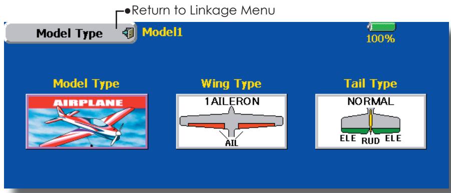
(The display screen is an example. The screen depends on the model type.)
Model type selection
- Call the Type select screen by touching the model type, wing, tail, swash type, or other type button.
- Select the type you want to set, and execute type selection by touching [Yes] at the confirmation screen. (When you want to cancel model type selection, touch [No].)
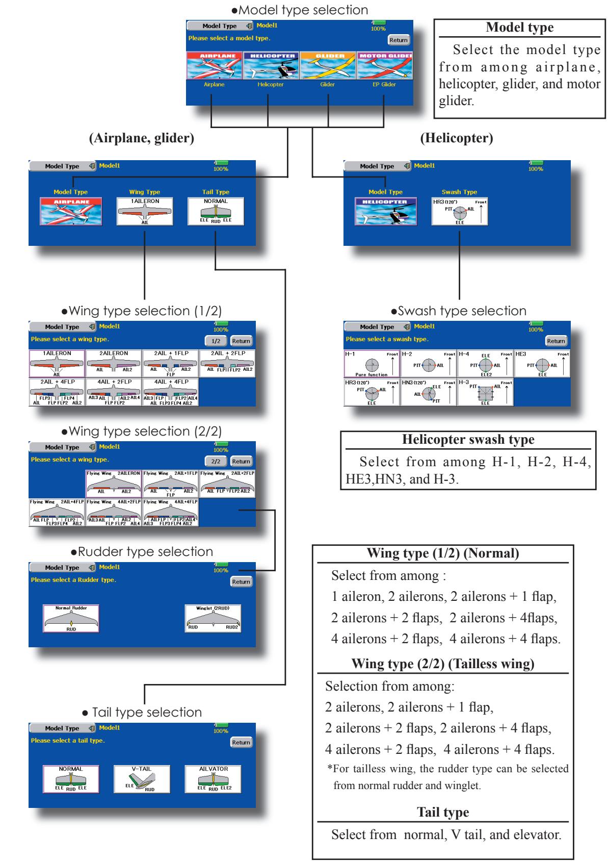
Picture
A picture can be pasted for each model. (Simplifies identification of the model data during screen operation.)
A photograph of the model taken with a digital camera or other file can be pasted as the screen display data for each model. This is convenient in identifying models with the same model name.
The picture files which can be displayed on the screen are size 168 x 80 pixels, file type .bmp (bit map picture) files. If a file larger than this is pasted, the top left-hand side of the picture is displayed.
Paste the picture after saving the picture data from your PC to the accessory CF card and inserting the CF card into the transmitter.
When a picture is pasted, it is displayed as the following screen image:
- Model Select screen
Home screen -
Startup screen
-
Touch the [Picture] button in the Linkage Menu to call the setup screen shown below.
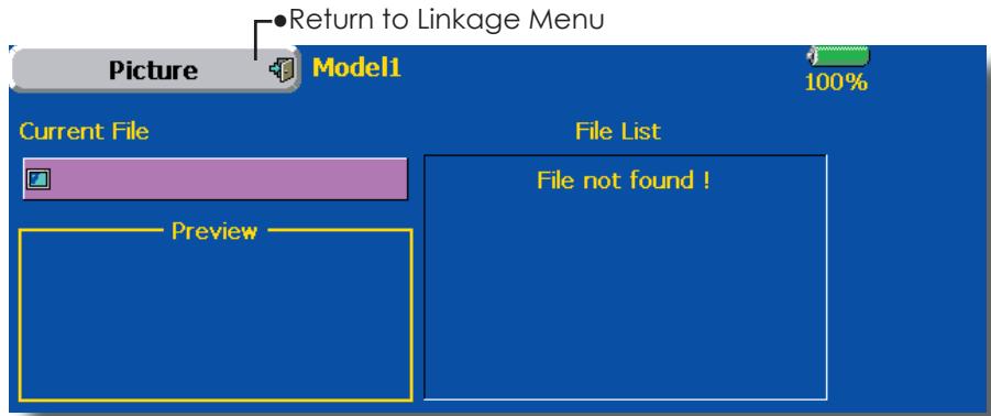
Pasting of picture
*Picture data is pasted to the model memory currently in use.
- Select the picture from the file list by touching the desired picture data.
*Before selection, touch the scroll button at the top or bottom of the file list and confirm the contents of the picture files saved on the CF card at the preview screen. - To paste the picture, touch [Yes]. (When you want to cancel pasting, touch [No].)
[Important]
Before reading data from the PC, insert the CF card into the transmitter and turn on the power. The following folders are automatically written. To read a file from the PC, copy the file to a folder by file type.
BMP: Picture file
WAV: Audio file
WMA: Music file
-MODEL: Model data
Sound
Sound recording and playback.
Sounds recorded with the microphone built into the transmitter and audio files (.wav) saved on the CF card from the PC can be played back when the power switch is turned on and off or by preset switch.
The recording time from the microphone is up to 3 seconds/ recording. Twenty-four audio files can be saved.
When recording, insert the CF card into the transmitter.
*The only audio file type which can be recorded is .wav. Only the sounds recorded with the built-in microphone or an audio file saved from your PC to the data pack can be played back.
Setup screens No. 3 to 24 can be individually assigned to audio file switches, etc. The playback
files can be switched each time the same switch is operated. This can be used when playing back the name of maneuvers, etc.
[Sound starting]
No. 1: When transmitter power switch turned on
No. 2: When transmitter power switch turned off
No. 3~24: Switch can be set.
[Important]
Before reading data from a PC, insert the CF card into the transmitter and turn on the power. The following folders are automatically written. When reading a file from the PC, copy it to a holder by file type.
BMP: Picture file
WMA: Music file
WAV: Audio file
- MODEL: Model data
- Touch the [Sound] button in the Linkage Menu to call the setup screen shown below.
![FUTABA 14MZ - [Important] - 1](/content/2025/01/163546/images/ff784018af499b69f7d47bd8a9c4f32120bd8a2c6c3dd95a63c227191edc982a.jpg)
![FUTABA 14MZ - [Important] - 2](/content/2025/01/163546/images/31417e80ffd81f3e481b2f22b7deccd31d2d5fa7d9236b828f21b9df19b29c9f.jpg)
(SAVED sound file)
Voice Recording
- Touch any REC button to call up the SOUND REORDER screen.
- Touch the REC button to start recording. (Recording time: 3 seconds)
- Record your voice as you are facing the transmitter's microphone.
- To finish, press "CLOSE". (The voice file is stored in the Data-Pack automatically.)
Also sound files created by your PC may be played back by assigned switches. (File types; .wav file only)
*You can only assign a sound data stored from your PC to a Data-Pack.
Assignment of audio files to switches
*Audio files can be saved to CF card beforehand.
- Touch the file button of the No. you want to set. A list of the files stored on the CF card is displayed.
- Select the audio file you want to play back from the list of audio files.
*Since the audio files are played back when the audio file names in the list are touched, the file contents can be checked before assignment.
- Touch the [File] button to assign the files.
- (Switches are also selected for No. 3~24.)
Touch the [NULL] button to call the Switch select screen.
- Select the switch and its ON direction at the Switch select screen.
(For a detailed description of the selection method, see "Switch setting method" at the back of this manual.)
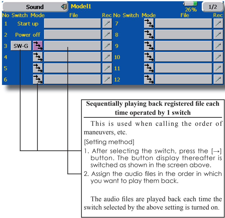
Frequency
Frequency Band (frequency) setting, modulation mode setting, receiver ID code setting.
Frequency setting
The T14MZ transmitter uses a synthesizer system. Its frequency can be changed within the range of the frequency band of the module used.
The frequency of the R5014DPS receiver is set from the transmitter. Use a receiver matched to the frequency band of the transmitter.
Receiver ID code
When the R5014DPS receiver (PCM-G3 receiver) is used, the ID code located on the back of the receiver case must be entered.
*When two receivers are used with a large model, etc., enter the 2nd receiver ID also.
- Touch the [Frequency] button in the Linkage Menu to call the setup screen shown below.
Modulation mode selection
With the T14MZ, 3 modulation modes (PCM-G3/ PCM1024/PPM (FM)) can be selected. Select the modulation mode matched to the type of receiver used.
*After changing the modulation mode, switch the modulation mode by turning the transmitter power off and on.
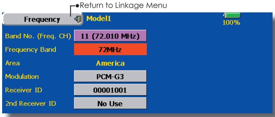
Frequency switching method
For a description of the frequency switching and ID setting methods, refer to the procedure given in the Basic Operation section.
Modulation mode change
- Touch the Modulation Mode button to call the selection screen, and then touch the button of the type of modulation used.
- Touch the [Enter] button to switch the mode.
*When switching from the PCM-G3 mode to another mode, the mode cannot be switched if the number of channels is insufficient due to the wing type used.
- After switching the modulation mode, turn the transmitter power off and then switch the mode by turning the transmitter power back on.
Receiver ID code input
- Touch the receiver ID No. on the screen. The receiver ID setup screen is displayed. Input the 8-digit ID number displayed on the back case of the receiver.
- If the ID number is correct, touch the [Enter] button. To correct the number, use the [BS] button and change the number to the correct ID code.
*Once the ID code is set, it does not have to be set again as long as the receiver is not changed.
WARNING
When flying after frequency change, emit radio waves only after verifying the frequency.
*Also change the frequency clip. Emitting radio waves without verification is extremely dangerous.
Function
Channel assignment of each function can be changed.
When you select model and wing (swash) types, you will find that the optimized combinations of servo output channels and functions have been already preset. If you would like, on the function-setting screen of the linkage menu, you can freely change combinations of servo output channels, functions (aileron, elevator, etc), and input controllers (sticks, switches, trim levers and trim switches). You can also assign the same function to multiple servo output channels such as assigning elevator function to CH2 and CH3.
DG1, DG2 (switch channels)
These two channels can be used as switch channels. You can freely change combinations between servo output channels and input controllers (sticks, switches, trim levers and trim switches).
VC1~VC4 (virtual channels)
These four channels can be set as virtual functions that do not have servo output channels. You can freely change combinations between functions (aileron, elevator, etc) and input controllers (sticks, switches, trim levers and trim switches).
Note: In PCMG3 mode, combinations of three channels such as CH 1 through CH 3, CH 4 through CH 6, CH 7 through CH 9 and CH 10 through CH 12 work simultaneously. Futaba recommends that you use the standard optimized default combinations of channels and functions in order to minimize servo delay when you use multiple servos to control models such as swash mode helicopters and dual elevator airplanes or flaperon airplanes.
Servo Output Channels
For PCMG3 mode, you can set twelve linear channels and two digital channels. For PCM1024 mode, you can set eight linear channels and one digital channel. For PPM mode, you can set only eight linear channels.
- Touch the [Function] button in the Linkage Menu to call the setup screen shown below.
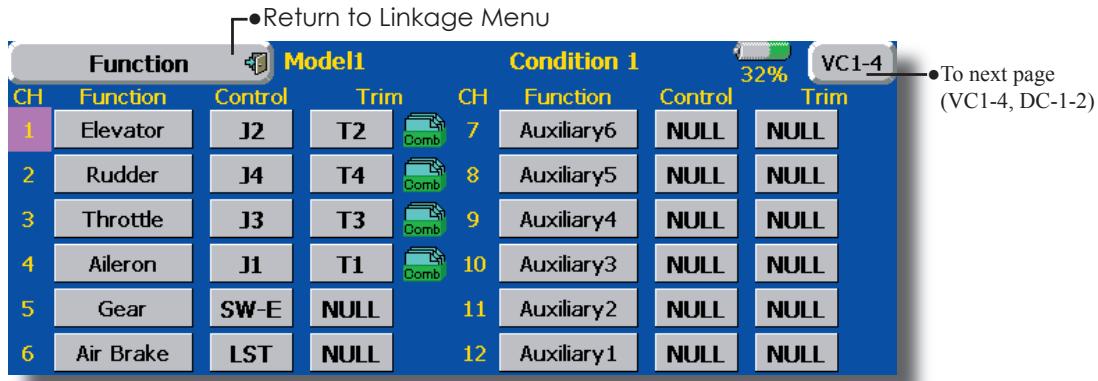
(The display screen is an example. The screen depends on the model type.)
Function change
- Touch the function button of the channel you want to change to call the function list.
- Select the function you want to change.
- Touch [Yes]. The display returns to the original screen. (When you want to cancel function change, touch [No].)
*Multiple channels can be assigned to 1 function.
Operation control change
- Touch the control button of the channel you want to change. A Control select screen (stick, switch, knob, trim lever, etc.) is displayed.
- Select the control you want to operate.
- Touch [Close]. The display returns to the preceding screen.
*The same control can be assigned to multiple channels.
Trim change
- Touch the Trim button to call the Trim setup screen.
-
The following items can be set at the Trim setup screen.
-
Hardware setting (Selection of switch, etc. which controls trim) (The select screen is called by touching the [H/W Select] button.)
- Rate setting
Operation step setting - Trim mode setting
Normal mode: Normal trim (parallel shift trim) operation
ATL mode: ATL operation mode. Reverse is also possible.
CTRM mode: Maximum change near center by center trim operation
- Separate/combination mode: Trim data are set to flight conditions
Separate mode: Trim adjustment for each flight condition
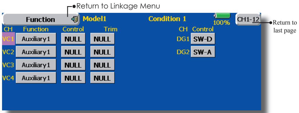
(The display screen is an example. The screen depends on the model type.)
Sub-Trim
Setting of neutral position of each servo.
The Sub-Trim function is used to set the servo neutral position, and may be used to make fine adjustments to the control surface after linkages and pushrods are hooked up. When you begin to set up a model, be sure that the digital trims are set to their center position.
- Touch the [Sub Trim] button in the Linkage Menu to call the setup screen shown below.
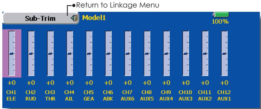
(The display screen is an example. The screen depends on the model type.)
Sub trim adjustment
- Touch the trim display part of the channel you want to adjust.
Adjustment buttons appear on the Sub Trim menu screen.
- Use the adjustment buttons to adjust the sub trim.
Initial value: 0
Adjustment range: -240~+240 (steps)
*See above
- Repeat this step for each channel.
Servo Reverse
Use to reverse the throw direction.
Servo Reverse changes the direction of an individual servo's response to a control stick movement.
For CCPM helicopters, be sure to read the section on Swash AFR before reversing any servos. With CCPM helicopters, always complete your servo reversing prior to any other programming. If you use pre-built Airplane/Sailplane functions
that control multiple servos, it may be confusing to tell whether the servo needs to be reversed or a setting in the function needs to be reversed. See the instructions for each specialized function for further details. Always check servo direction prior to every flight as an additional precaution to confirm proper model memory, hook ups, and radio function.
- Touch the [Servo Reverse] button in the Linkage Menu to call the setup screen shown below.
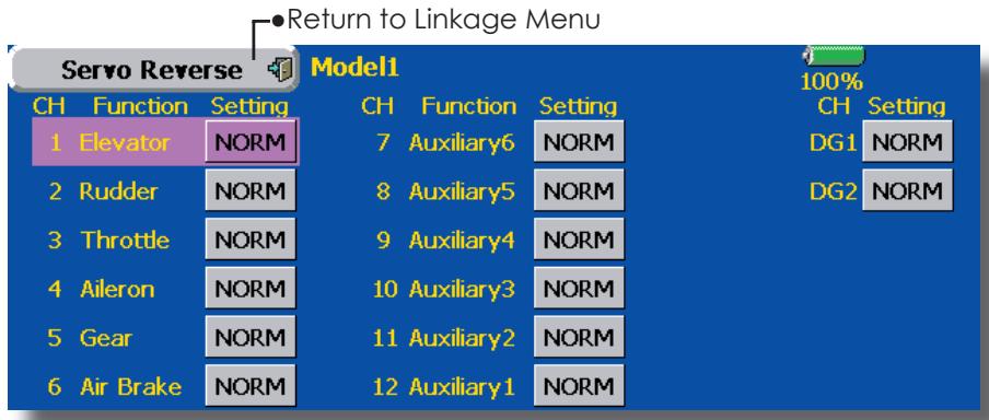
(The display screen is an example. The screen depends on the model type.)
Servo reversing procedure
After setting up a new model, be sure to define all special menus. Be sure that all servos are plugged into the proper receiver channels. Now, determine whether you need to reverse any channels by moving each stick and observing the corresponding movement in the model's controls.
- Touch the desired channel's Setting button to choose the proper direction for the servo
- Touch "Yes" in the next screen.
- Repeat for each servo needing reversal.
When done, touch "Servo Reverse" to return to the Linkage Menu.
Fail Safe
Sets the servos operating position when transmitter signals can no longer be received or when the receiver battery voltage drops.
The Failsafe function may be used to set up positions that the servos move to in the case of radio interference.
This function only works with G3 or PCM receivers (FM receivers do not have failsafe capability).
When the receiver battery voltage drops, the servo can be moved to a preset position. (Battery fail safe function) A battery fail safe function reset switch can be set. (Initial setting: Throttle stick maximum slow side)
You may set either of two positions for each channel: Hold, where the servo maintains its last commanded position, or Failsafe, where each servo moves to a predetermined position. You may choose either mode for each channel.
The T14MZ system also provides you with an advanced battery monitoring function that warns you when the receiver battery has only a little power remaining. In this case, each servo is moved to the defined failsafe position. The battery
- Touch the [Fail Safe] button in the Linkage Menu to call the setup screen shown below.
fails may be released by operating a predefined control on the transmitter (default is throttle), do not continue to fly, land as soon as possible. Remember, if the predefined control suddenly moves to a position you did not command, land at once and check your receiver battery.
Defines servo position when signals are lost and when receiver battery voltage becomes low.
WARNING
For safety, always set the fail safe functions.
- Especially set the throttle channel fail safe function so that the servo moves to the maximum slow side for airplanes and to the slow side from the hovering position for helicopters.
Crashing of the model at full high when normal radio waves cannot be received due to interference, etc., is very dangerous.
- If fail safe is reset by throttle stick, it may be mistaken for an engine malfunction and will be reset at throttle slow and the model will continue to fly. If you have any doubts, immediately land.
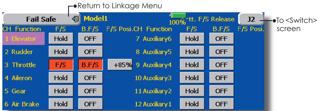
(The display screen is an example. The screen depends on the model type.)
Fail safe setting procedure
Decide which channels you want to go to preset positions, and which ones you want to maintain their last commanded position. To select the failsafe mode you wish to set, use the F/S button. This button toggles between the two modes. (Hold, F/S)
F/S mode setting:
- Touch the F/S button of the channel you want to set, and set that channel to the [F/S] mode.
- Hold the corresponding stick, control, slider, or other control in the position you want the servo to move to when the fail safe function is activated, and touch the F/S position button. That position is displayed in percentage.
*When you want to return that channel to the Hold mode, touch the [F/S] button again.
Battery fail safe setting procedure
To select the B.F/S mode, touch the [B.F/S] button. Each time the button is touched, it toggles
between [OFF] and [B.F/S].
B.F/S setting:
- Touch the [B.F/S] button of the desired channel to set it to the B.F/S mode.
- Hold the corresponding stick, VR, slider, or other control in the position you want the servo to move to when the battery fail safe function is activated, and touch the F/S position button. This position is displayed in percentage.
*When you want to return that channel to OFF, touch the [B.F/S] button again.
Battery Failsafe Release Function
This function releases the predefined control from it's held position after indicating that your receiver battery is low.
- Enter the control setting screen by touching the Battery F/S Release button. Now, you may choose that moving the throttle resets the condition, or select another stick or switch deactivates it. To set a desired throttle release position, move the throttle stick to the point at which you wish the B.F/S to be released.
End Point (ATV)
Sets the travel, limit point, and speed of each servo.
The End Point function adjusts the left and right servo throws, generates differential throws, and will correct improper linkage settings.
The Travel rate can be varied from 30% to 140% in each direction on channels 1 to 12. Also, the Limit point where servo throw stops may be varied from 0% to 155% .
NOTE: The indicators on the screen display actual servo throw of the each channel. The center position of the indicator is based on the Sub-Trim settings. Therefore the Sub-Trim adjustment changes the Limit point display of the indicator. The Servo Speed setting is used to set the servo delay for each channel, from channel 1 to channel 12. The system uses the programmed speed (delay) to slow down servo position changes. The Servo Speed setting can be varied from 0 to 20 in each channel.
- Touch the [End Point (ATV)] button in the Linkage Menu to call the setup screen shown below.
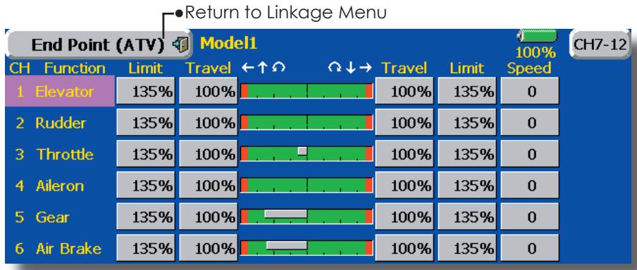
(The display screen is an example. The screen depends on the model type.)
Servo travel adjustment
- Touch the Travel button of the channel you want to set. Adjustment buttons appear on the screen.
- Use these buttons to adjust the rate.
Initial value: 100%
-
Adjustment range: 30% 140%
-
Repeat the procedure above for each rate.
Limit point adjustment
- Touch the Limit button of the channel you want to set.
- Use the adjustment buttons to adjust the limit point.
Initial value: 135%
- Adjustment range: 0% 155%
- Repeat this procedure for each limit point.
Servo speed setting
- Touch the Speed button of the channel you want to set.
-
Use the adjustment buttons to adjust the servo speed.
Initial value: 0
Adjustment range: 0~25 (steps) -
Repeat this procedure for each channel.
To close this screen, touch the [End Point (ATV)] button.
Throttle Cut
Stops the engine safely and easily.(airplane and helicopter only)
Throttle cut provides an easy way to stop the engine, by flipping a switch with the throttle stick at idle. The action is not functional at high throttle to avoid accidental dead sticks. The switch's location and direction must be chosen, as it defaults to NULL.
- Touch the [Throttle Cut] button in the Linkage Menu to call the setup screen shown below.
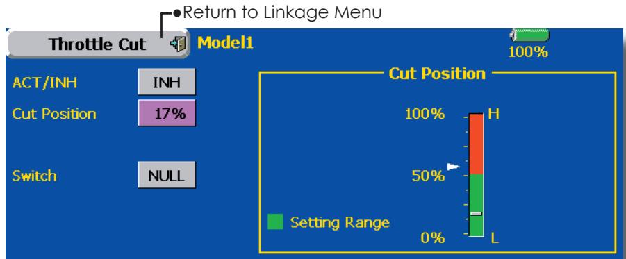
(The display screen is an example. The screen depends on the model type.)
Throttle cut setting procedure
- Touch the "INH" button to activate the Throttle Cut function.
- Throttle cut function switch setting:
Touch the "NULL" button to call the
(For a detailed description of the selection method, see [Switch Setting Method] at the back of this manual.)
- Throttle cut position setting:
Set the throttle stick to maximum slow, and touch the Cut Position button. Adjustment buttons appear. At the same time, the numerical value of the current maximum slow side is displayed at "Cut Position".
Use the adjustment buttons to adjust the servo travel when the throttle cut function is activated.
Initial value: 17%
- Adjustment range: 0% 50%
*With throttle stick at idle, adjust the rate until the engine consistently shuts off, but throttle linkage is not binding. When finished, touch the "Throttle Cut" button to exit.
To exit the setting, touch the [Throttle Cut] button.
Idle Down
Lowers the engine idling speed.(airplane and helicopter only)
The Idle Down function lowers the engines idle by flipping a switch with the throttle stick at idle. The action is not functional at high throttle to avoid accidental dead sticks. The switch's location and direction must be chosen, as it defaults to NULL.
- Touch the [Idle Down] button in the Linkage Menu to call the setup screen shown below.
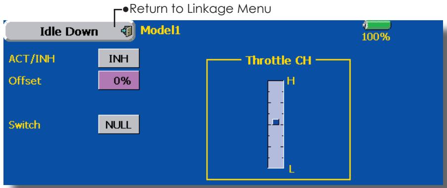
(The display screen is an example. The screen depends on the model type.)
Idle down setting procedure
- Touch the "INH" button to activate the Idle Down function.
- Idle Down function switch setting:
Touch the "NULL" button to call the
(For a detailed description of the selection method, see [Switch Setting Method] at the back of this manual.)
- Offset rate setting:
Touch the Offset Rate button. Adjustment buttons appear on the screen.
Use these buttons to adjust the offset rate.
Initial value: 0%
- Adjustment range: 0% 100%
To exit the setting, touch the [Idle Down] button.
Neutral Point
At your linkages, if the servo horn deviates from a perpendicular position at neutral, the linkage compensation functions in this menu may not compensate effectively. To correct this use the Hovering Point function. This will, move the neutral point of the servos to the actual perpendicular position. However, this adjustment changes only the datum point of the compensation functions in this menu, and does not affect the neutral position of other functions.
Swash AFR
Swash AFR function reduces/increases/reverses the rate (travel) of the aileron, elevator and collective pitch functions, by adjusting or reversing the motion of all servos involved in that function, only when using that function. Since H-1 uses one servo for each function, there is no need for Swash AFR in H-1.
- Touch the [Swash] button in the Linkage Menu to call the setup screen shown below.
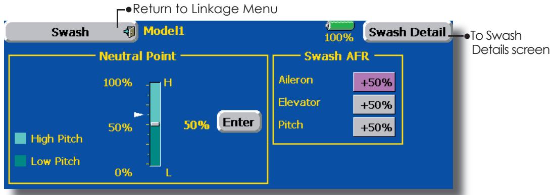
Neutral point setting procedure
Before using the correction function, set the neutral point.
Adjusting the servo horn so that the neutral point is near the 50% position makes the mixing amount small.
- Hold the servo horn at a right angle to the linkage rod, and then touch the [Enter] button and read the actual neutral position.
*The neutral position is displayed on the screen.
After reading the neutral point, use the other correction functions to make further adjustments.
To exit the setting, touch the [Swash] button.
Swash AFR setting procedure
- Touch the button of the AFR rate to be adjusted. Adjustment buttons appear on the screen.
- Use these buttons to adjust the AFR rate.
Initial value: +50%
- Adjustment range: -100%~+100%
To exit the setting, touch the [Swash] button.
Mixing Rate
This compensation mixing is used to correct the tendency of the swash-plate for each control near the hovering point. The following compensation mixings is possible; PIT to AIL, PIT to ELE, AIL to PIT, ELE to AIL, and ELE to PIT. It adjusts the swash-plate to operate correctly for each control near the hovering point using the corresponding compensation mixings.
Linkage Compensation
This compensation mixing is used to correct the tendency of the swash-plate for pitch control at low pitch and high pitch. It adjusts the swash-plate to move horizontally for collective pitch control using the corresponding compensations.
Elevator Delay/Speed Compensation
This function is used to cancel the reaction when the swash-plate moves in the vertical direction by sudden elevator changes. The delay amount of elevator can be programmed.
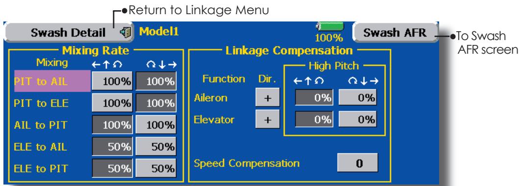
Mixing rate setting procedure
- Touch the Mixing Rate button you want to set. Adjustment buttons appear on the screen.
- Use these buttons to adjust the mixing rate.
Initial values:
PIT to AIL, PIT to ELE, AIL to PIT: 100%/100%
ELE to AIL, ELE to PIT: 50%/50%
To end setting, touch the [Swash Details] button.
Linkage correction setting procedure
-
Adjust the rate with the adjustment buttons.
-
Adjustment range: 0% 100%
Note: When using the linkage correction function, readjust swash AFR for maximum blade angles because the maximum rudder angle changes.
To end setting, touch the [Swash Details] button.
Speed correction setting procedure
- Use the adjustment buttons to adjust the delay.
Initial value: 0
Adjustment range: 0~100
To end setting, touch the [Swash Details] button.
Timer
Timer setting and lap time display.
The Timer function may be set for any desired time, i.e. engine run time, specified times for competitions, etc. Two independent timers are provided for your use. The timers are stored independently with each model, meaning that when you switch between model setups, the timer associated with the new model is brought up automatically.
The timers may be set to start and stop from the motion of any switch or stick. You may set the ON and OFF directions freely. Each timer has a capacity of up to 59 minutes 59 seconds.
Each timer may be set for count-down or count-up operation with a target time. Also Split Time may be counted.
If a target time is set and the timer reaches the set time, a buzzer sound for each count is generated.
Countdown timers sound one short beep during the last twenty seconds and two short beeps during the last ten seconds before reaching the target, then a long tone at the target time, and continue counting with displaying a minus (-) sign. Count-up timers also beep the last twenty and ten seconds, beep the target time, and keep counting upwards until shut down.
- Touch the [Timer] button in the Linkage Menu to call the setup screen shown below.
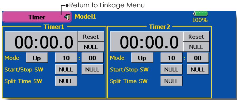
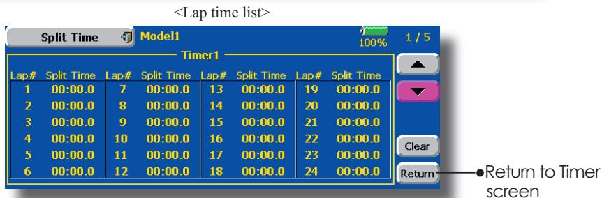
Up timer/down timer selection
- Touch the mode button and select the type of timer.
*Each time this button is touched, it toggles between UP and DOWN.
- Timer time setting
Touch the Mode minutes or seconds button.
Adjustment buttons appear on the screen.
Use these buttons to set the timer time.
Start/stop switch setting
- Touch the Start/Stop SW "NULL" button to call the
screen, and then select the switch and its ON direction.
(For a detailed description of the selection method, see [Switch Setting Method] at the back of this manual.)
Lap time switch selection
- Touch the Lap SW "NULL" button to call the Prog. Mix screen, and then select the switch and its ON direction.
(For a detailed description of the switch setting method, see [Switch Setting Method] at the back of this manual.)
Timer operation
- Timer 1 and Timer 2 are started and stopped by start/stop switch set beforehand.
- To count the lap time, operate the lap time switch selected beforehand. Each time this switch is operated, the lap time is stored. To display the lap time, touch the respective [List] button.
- To reset a timer, touch the respective [Reset] button.
To exit the setting, touch the [Timer] button.
Dial Monitor
LDisplays the position of the dials, slider levers, and digital trim.
Digital Trim Position display (T1-T6, CD)
The Dial Monitor displays the current position and the operation step amount of each Digital Trim.
VR and slide lever position display (LST, LS, LD, RD, RS, RST)
Displays the current position (black) and last operating position (green) of the VRs and slider levers.
- Touch the [Dial Monitor] button in the Linkage Menu to call the setup screen shown below.
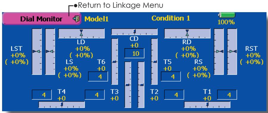
Knob and Lever Position display (LD, RD, LS, LST, RS, RST)
The Dial Monitor displays the current position and last operation position of each knob and lever. Although neither knob nor lever can hold the last operation position because of they are "analog" type, the position data during the last operation is memorized in the model memory. By moving the knob and lever to the position displayed on this monitor, the last operation position is recalled.
Recalling Dial Position
(LST, LS, LD, RD, RS, RST)
The dial position data at the last operation is displayed for each knob and lever in this monitor. (Green arrow)
- Move the black arrow (current position) to the green arrow position by operating the desired knob or lever to recall the last operating position.
Data Reset
Model memory setting data reset. (by item)
This function is designed to allow you to reset selected portions or all of the settings saved in the active model memory. You may individually choose to reset the following sets of data;
T1~T6, CD:
Reset the digital trim setting.
*All the conditions, or the condition currently being displayed (the entire group for group setting), can be selected.
Direct key:
Resetsdirectkeyassignment.
Model menu setting:
Resets all the functions in the Model Menu except Condition Select.
All model setting:
Resets all Linkage and Model Menu functions except for Frequency, Model Select, and Model Type.
- Touch the [Data Reset] button in the Linkage Menu to call the setup screen shown below.
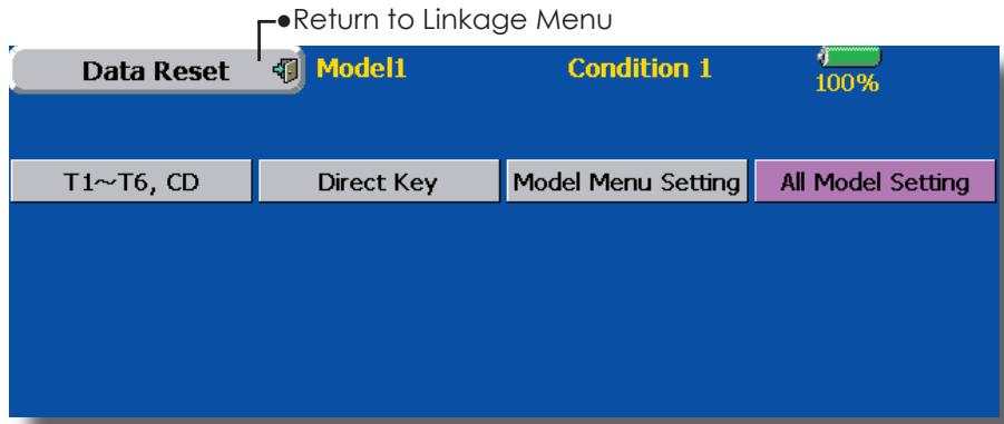
Data Resetting
- Touch the desired button to reset the set of data.
- Perform the data resetting according to the instructions displayed on a screen. When complete, touch the Data Reset button to exit.
MODEL MENU (COMMON FUNCTIONS)
This section describes the AFR, program mixing, and other functions common to all model types.
Before setting the model data, use the Model Type function of the Linkage Menu to select the model type matched to the fuselage. When another model type is selected thereafter, the AFR, program mixing, and other setting data are reset.
The functions in the Model Menu can be set for each flight condition. When you want to use the system by switching the settings for each condition by switch, stick position, etc., use the Condition Select function to add flight conditions. (Up to 8 conditions can be used)
Note: The T14MZ is designed so that the airplane and glider (including EP glider) model types are compatible with fuselages of similar type wings. This section outlines the relationship between the functions common to airplanes and gliders, except some dedicated functions, and model type. The setting items depend on the number of servos and other differences according to the wing type used, but reread them. The setup screens in the instruction manual are typical examples.
- Touch the Model Menu button of the Home screen to call the Model Menu.
- When the button of the function you want to set is touched, a setup screen appears.
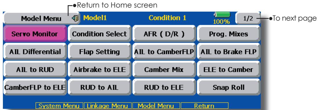
(Model Menu screen example)
*The Model Menu screen depends on the model type. This screen is for model type 4AIL+4FLP.
Model Menu functions (Common) list
Servo Monitor
Servo test and servo position display (For a description of its functions, see the Linkage Menu section.)
- Condition Select
Flight conditions addition, deletion, copy, condition renaming, and condition delay can be set.
- AFR (D/R)
Sets the rudder angle and curve of all the operation functions. A D/R curve which can be switched with a switch, etc. can also be added.
-Prog.Mixes
Program mixing which can be freely customized. Up to 10 mixes can be used for each condition.
-Fuel Mixture
Mixing used in needle adjustment of engines which use a fuel mixture control carburetor. [Airplane, helicopter]
Condition Select
Flight conditions addition, deletion, copy, condition renaming, and condition delay can be set. [All model types]
The functions in the Model Menu can be used by switching the settings of up to 8 flight conditions by using the Condition Select function to add flight conditions. Add conditions, as required.
When you do not want to use the Condition Select function, this setting is unnecessary. In this case, use the flight conditions (Condition 1) assigned at initial setting.
- Since switching by stick and lever position, in addition to ordinary toggle switch, is possible as the flight condition selector switch, this function can be linked with other operations.
- A Condition Delay function can be set. Unnecessary fuselage motion generated
when there are sudden changes in the servo positions and when there are variations in the operating time between channels during condition switching can be suppressed. The delay can be set for each channel.
When setting the delay function at the switching destination condition, the related function changes after a delay corresponding to the set amount.
- When multiple conditions were set, their operation priority can be freely changed.
-
The condition name can be changed. The selected condition name is displayed on the screen. When a condition has been added, give it a name which can be easily confirmed.
-
Touch the [Condition Select] button in the Model Menu to call the setup screen shown below.
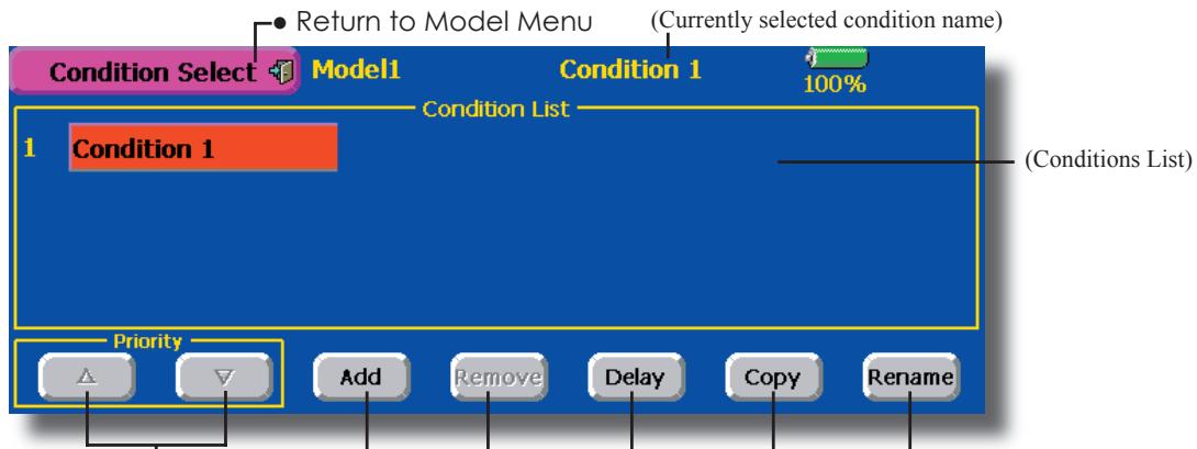
Priority change
- Touch the condition whose priority you want to change in Conditions List.
- Change the priority with the priority [] or [] button. (The last condition has the highest priority.)
*The initial setting condition cannot be moved. It has the lowest priority.
Condition Addition
- When the [Add] button is touched, the Condition Select screen appears.
*Only the number of buttons corresponding to the conditions which can be added are displayed. - Select the desired conditions by touching the buttons.
*The selected conditions are added to Conditions List. - Touch the [NULL] button to call the
screen. - Select the switch to be used in condition switching and its ON direction.
(For a description of the switch selection method, see [Switch Setting Method] at the back of this manual.)
5. The "Condition 1" data for the added conditions is copied.
-Condition delay setting
(For a description of the setting method, see the next page.)
Condition Reset
- Select the condition by touching the condition you want to reset in Conditions List.
- Touch the [Reset] button.
- When the [Yes] button is touched, the condition is reset. (To abort resetting, touch the [No] button.)
Condition Renaming
- Select the condition by touching the condition you want to rename in Conditions List.
- Touch the [Rename] button.
- Enter the new name from the keyboard which appears on the screen. (For a description of the method of using the Japanese language conversion mode, see "Characters Input Method" of the Basic Operation section.)
- When the keyboard [Return] key is touched, the new name is registered. (To abort registration, touch the [ESC] key.)
Condition Copy
- Touch the [Copy] button. The Copy screen appears.
- Select the condition by touching the button of the copy source conditions.
- Next, select the condition by touching the copy destination condition.
- Touch the [COPY] button.
-
When the [Yes] button is touched, the data is copied. (To abort copying, touch the [No] button.)
-
Touch the [Delay] button on the Condition Select screen to call the Condition Delay screen shown below.
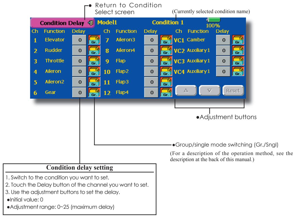
Condition Hold (Helicopter Only)
This function may be used to limit the maximum speed of the engine so that you may adjust flight conditions when the engine is running. The maximum throttle position is settable, and an alarm indicates that the function is operating. The function is especially useful for helicopters, because it will prevent the engine from racing dangerously when adjusting the Idle-Up settings.
While this function is active, the throttle operates on the default condition throttle curve, and mixing is applied as normal, except the throttle is not allowed to move past the set point.
You must deactivate this function when you are through making adjustments. The system will not allow you to deactivate this function in either of the following states:
- When any of the flight condition switches are on.
- When the throttle stick is higher than the set point.
To activate Condition hold:
- Set the throttle stick at a position 3/4 below full throttle.
- Press the Condition Hold box in the lower left hand corner of the Model Menu or Linkage Menu screens.
AFR (D/R)
The rudder angle and curve of each operation function can be set. A D/R curve which can be switched by switch, etc. can also be added. [All model types]
AFR function is used to adjust the throw and operation curve of the stick, lever, and switch functions (CH1 to CH12, and V1 to V4) for each flight condition. This is normally used after End Point (ATV) has defined the maximum throw directions (End Point acts on ALL flight condition settings). When mixing is applied from one channel to another channel, both channels can be adjusted at the same time by adjusting the operation rate through the AFR function.
Setting method
- Operation curve adjustment: Six types of curves (linear, EXP1, EXP2, VTR, line and spline) can be selected. A maximum 17 points curve can be used for the line and spline curve types. (Initial setting: 9 points) The number of points can also be increased and decreased and curves from complex curves to simple curves can be used.
-
Operation speed adjustment: The operation speed of each function when the function is operated (including at flight condition switching) can be adjusted. The function operates smoothly at a constant speed corresponding to the set speed.
-
Touch the [AFR (D/R)] button in the Model Menu to call the setup screen shown below.
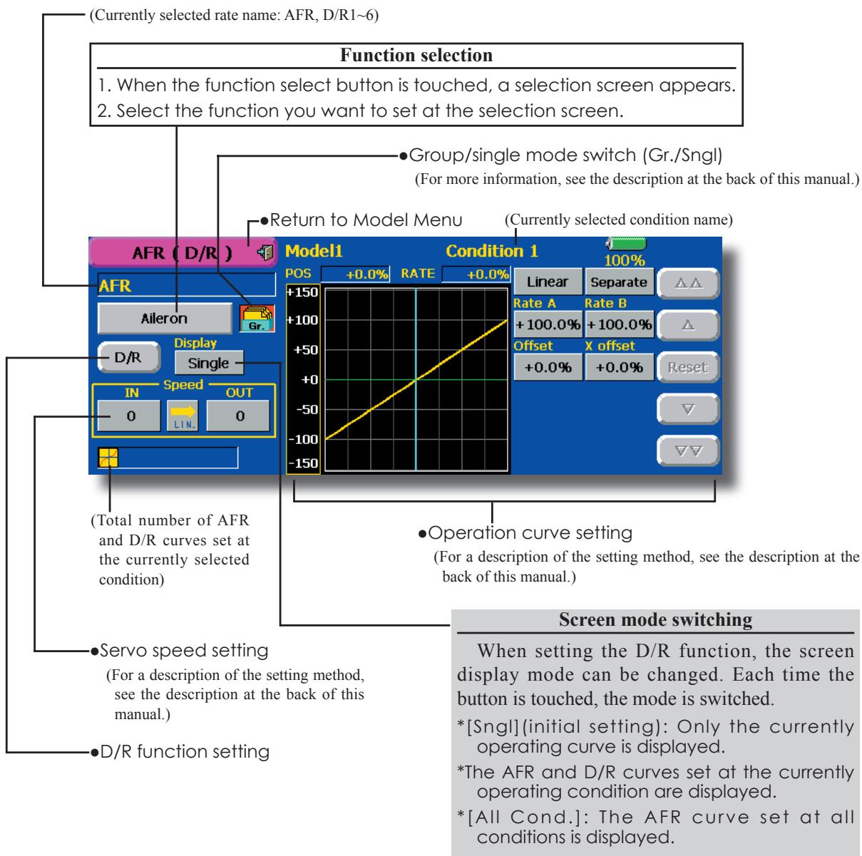
Dual Rate setting
Up to 6 dual rates can be set for each condition.
^D / R (Dual Rate) is set for each condition, and is not reflected at other conditions.
^D / R (Dual Rate) at the top of the D/R list has priority.
Setting method
- Touch the [D/R] button from the AFR (D/R) screen of the function (ailerons, elevators, etc.) whose dual rate you want to set. The D/R list screen shown below is displayed. Touch the (function) button of the dual rate number to be assigned. That rate is automatically assigned to that function.
- Next, select the switch and its ON/OFF directions.
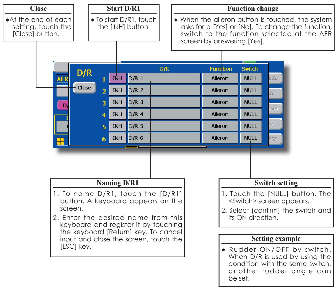
Prog. Mixes
Program mixing which can be freely customized. Up to 10 mixings can be used for each condition. [All model types]
Programmable mixing may be used to correct undesired tendencies of the aircraft, and it may also be used for unusual control configurations. Mixing means that the motion of a command channel, called the "master," is added to the motion of the mixed channel, called "slave."
You may choose to have the Masters trim added to the Slave channel response, if you desire ("Trim" setting). The mixing curve can be changed so that the undesired tendencies can be corrected effectively by setting the LINEAR1/LINEAR2/EXP1/EXP2/VTR/LINE/SPLINE modes. The Delay function can be programmed for each rate. The Delay is used to change the rate smoothly when switching. You may define Mixing ON/OFF switch, control or you may choose to
have mixing remaining on all the time.
Offset-type mixing applies a fixed offset or preset to the programmed channel servo operation and may control up to four circuits simultaneously. The Programmable mixing includes a powerful link function, which allows Programmable mixing to be linked with the special mixing functions, or with other programmable mixing functions. The link function can be set up for Master and Slave channel individually.
The slave channel AFR mode (STK-STK mode) may be selected, where the slave channel AFR and D/R settings are observed when Link function is set. The knob for fine tuning can be set up for every mixing circuit. (Fine tune function)
- Touch the [Prog. Mixes] button in the Model Menu to call the setup screen shown below.
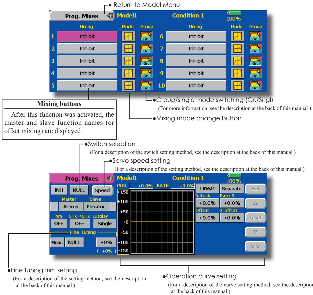
Setting methods
- Group/single mode selection
Activating functions for only the selected conditions:
- Touch the Group button and switch to the Sngl mode.
*Each time the button is touched, it toggles between the Gr. and Sngl modes. - Mixing mode selection
Using the offset mode:
- Touch the Mode button and switch to the Offset mode.
*Each time the button is touched, it toggles between the Mix and Offset modes. -
Mixing setup screen selection
-
Touch the button of the mixing you want to set. The mixing setup screen is displayed. Activate the function.
- Activate the function by touching the [INH] button.
*Each time this button is touched, it toggles between [INH] and [ON/OFF].
-
Mixing ON/OFF switch setting and ON/OFF direction switching
*An ON/OFF switch is not set even when the function is activated. -
When you want to turn mixing ON/OFF by switch, touch the [NULL] button to call the
screen and then select the switch and its ON direction.
*For a description of the selection method, see [Switch Setting Method] at the back of this manual.
- Master channel setting (except offset type mixing)
- Touch the Master button to call the Function menu and select the master channel.
- To link this mixing with other mixing, touch the button at the left of the master channel and select link.
*Each time the button is touched, it toggles between mixing direction + and - and "No display" (no link).
*Master channel control can be set to stick, VR, and other simple travels which do not include ATV, AFR, D/R, mixing setting, etc. In this case, display the
-
Slave channel setting
-
Touch the Slave button to call the Function menu and select the slave channel.
- To link this mixing with other mixing, touch the button at the right-hand side of the slave channel and select link.
*Each time the button is pressed, it toggles between mixing direction + and - and "No display" (no link).
-
Trim mode ON/OFF setting
-
To turn the trim mode ON/OFF, touch the Trim button on the screen.
When mixing includes master side trim, set the Trim button to [ON]. When mixing does not include master side trim, set the Trim button to [OFF].
Each time this button is pressed, it toggles between [ON] and [OFF].
*This is effective when the master channel is set by Function.
-
Slave channel AFR mode (STK→STK)
-
When Link is set at the slave side, and you want to add AFR (D/R) to the mixing rate, select [ON]. When you do not want to add AFR (D/R) to the mixing rate, select [OFF].
Each time this button is pressed, it toggles between [ON] and [OFF].
This is effective when making corrections when the fuselage is the same but the rudder angles are substantially different.
-
Mixing curve type selection
-
Touch the curve type selection button of the curve type you want to use to display the selection screen and then select the curve you want to use.
*For a description of the curve setting method, see the description at the back of this manual. -
Fine tuning trim setting
-
When using the curve fine tuning function, touch the [NULL] button of the Fine Tuning item to call the
screen and then select the lever, VR, etc. you want to use.
*For a description of the fine tuning trim setting method, see the description at the back of this manual.
Servo speed setting
- When setting the servo speed, touch the Speed button. The Servo Speed setup screen is displayed.
For a description of the servo speed setting method, see the description at the back of this manual.
Offset mixing changes the speed. Use the Speed In and Speed Out buttons to readjust the speed..
The mixing switch can set a delay with a different rate at starting and stopping.
*This function is inactive when a mixing switch is not set.
Fuel Mixture
Dedicated mixing used in needle adjustment of engines which use a fuel mixture control carburetor. [Airplane, helicopter]
This function is dedicated mixing used in needle adjustment of an engine that uses a fuel mixture control carburetor.
*The needle channel is assigned to CH9 as a default.
- Touch the [Fuel Mixture] button in the Model Menu to call the setup screen shown below.
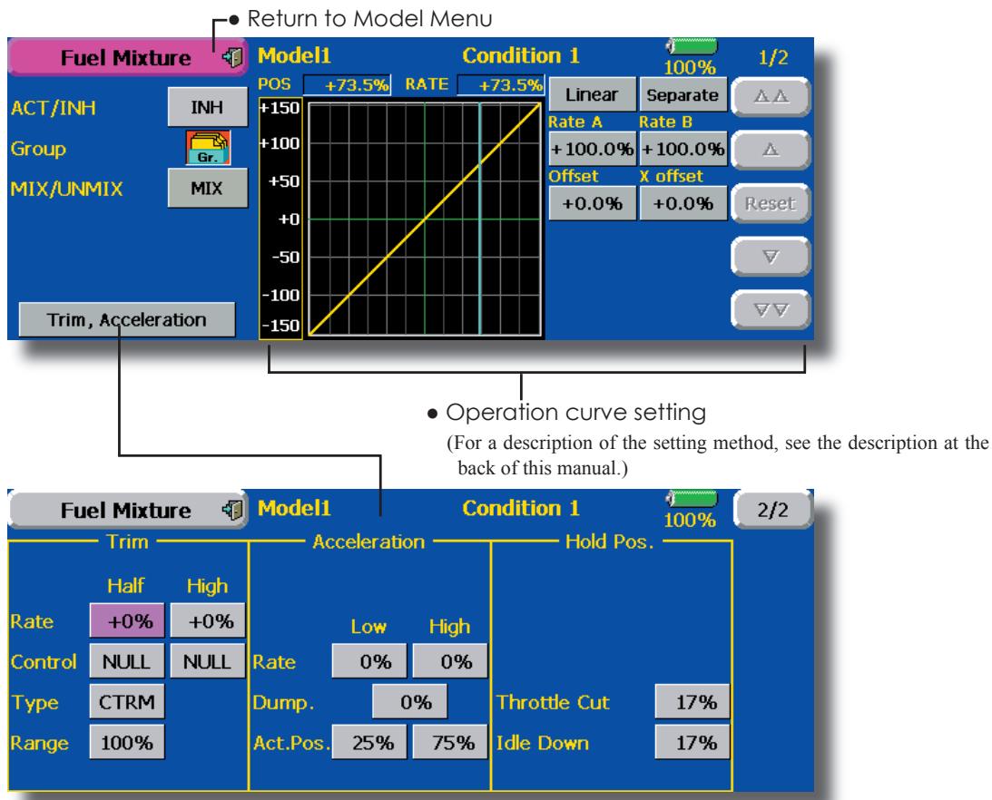
Setting method
CTRM mode: Maximum amount of change near center by center trim operation. When the adjustment range (Range) value is made small, trim is active only near the center.
NORM mode: Normal trim (parallel movement trim) operation. When the adjustment range (Range) value is made small, trim is active only near the center. Needle high trim works as high trim based on the center. This operation is similar to reverse ATL trim.
- An acceleration function can be set. This function is used when there are symptoms of the mixture being either too rich or too lean, which would be generated by sudden operation of the throttle stick.
An acceleration (ACLR) function and deceleration (DCLR) function, which temporarily increase and decrease the fuel supply at acceleration and deceleration, can be set.
- The return time after operation (Dump) can be set for both setting at acceleration (High) and setting at deceleration (Low).
- A needle throttle cut function can be set.
- Operation linked with the throttle hold functions (Cut and Idle), Throttle Cut function, and Idle Down function is possible.
- The needle side cut position can be set. Set it to the fuel side full open position.
When the MIX mode is selected, the throttle curve set data becomes the mixing master. In the UNMIX mode, the throttle stick position becomes the mixing master.
MODEL MENU (AIRPLANE/GLIDER FUNCTIONS)
The dedicated mixings, etc. usable when airplane, glider, or EP glider model type is selected are displayed in this Model Menu functions section. First use the Model Type function of the Linkage Menu to preset the model type, wing type, and tail type matched to the fuselage used. Later setting resets the data set by mixing function, etc.
These dedicated mixings can be set for each flight condition, as required. When you want to use the system by switching the settings for each
condition by switch or stick position, use the Condition Select function to add flight conditions. (Up to 8 conditions can be used)
Note: The T14MZ is designed so that the airplane and glider (including EP glider) model types can handle fuselages of the same wing type. The functions common to airplanes and gliders, except some dedicated functions, are summarized without regard to the model type. The setting items are different, depending on the number of servos, etc. according to the wing type used. However, reread them. The setup screens in the instruction manual are typical examples.
- Touch the Model Menu button of the Home screen to call this Model Menu.
- When the button of the function you want to set is touched, a setup screen appears.

(Model Menu screen example)
*The Model Menu screen depends on the model type. This screen is for model type 4AIL+4FLP.
Model Menu functions list
- AIL Differential
This function adjusts the left and right ailerons. Roll axis correction and fine tuning with a VR are also possible. This is convenient when making settings during flight.
[Airplane/glider, 2 ailerons or more]
- Flap Setting
The flaps can be adjusted independently. For a 4 flaps model, the camber flaps can be mixed with the brake flaps. [Airplane/glider, 2 flaps or more]
AIL to Camber FLP
This mixing operates the camber flaps in the aileron mode. It improves the operation characteristic of the roll axis. [Airplane/glider, 2 ailerons + 2 flaps or more]
- AIL to Brake FLP
This mixing operates the brake flaps in
the aileron mode. It improves the operation characteristic of the roll axis. [Airplane/glider, 4 flaps or more]
AIL to RUD
This mixing is used when you want to operate the rudder at aileron operation. Banking at a shallow bank angle is possible. [Airplane/glider, 2 ailerons + 2 flaps or more]
Airbrake to ELE
This mixing is used to correct operation of the airbrakes (spoilers) when landing. [Airplane/glider, general]
RUD to AIL
This mixing is used to correct roll maneuvers, knife edge, etc. of stunt planes. [Airplane/glider, general]
Camber Mix
This mixing adjusts the camber and corrects the elevators. [Airplane/glider, 2 ailerons or more]
- ELE to Camber
This mixing is used when you want to the mix camber flaps with elevator operation. Lifting force can be increased at elevators up. [Airplane/glider, 2 ailerons or more]
Camber FLP to ELE
This mixing is used to correct for attitude changes when the camber flaps are being used. [Airplane/glider, 2 ailerons + 1 flap or more]
-Butterfly (Crow)
This function is used when powerful brake operation is necessary. [Glider, 2 ailerons or more]
- Trim Mix 1/2
The ailerons, elevators, and flaps trim offset rate can be called by switch or condition selection. [Glider, 2 ailerons or more]
Airbrake
This function is used when airbrakes are necessary when landing or when diving, etc. during flight. (Airplane, general)
Gyro
This is dedicated mixing when a GYA Series gyro is used. [Airplane/glider, general]
V-tail
This function adjusts the elevators and rudder of V-tail models. [Airplane/glider, V-tail specifications]
Alevator
This function adjusts the elevators and ailerons of models with elevator specifications. [Airplane/glider, elevator specifications]
Winglet
This function adjusts the left and right rudders of winglet models. [Airplane/glider, winglet specifications]
Motor
The operation speed when the motor of F5B and other EP gliders is started by switch can be set. [EP glider, general]
RUD to ELE
This function is used to correct roll maneuvers, knife edge, etc. of stunt planes. [Airplane, general]
Snap roll
This function selects the snap roll switch and adjusts the steering angle of each rudder. Servo speed can also be adjusted. [Airplane general]
- Multi Engine
This function adjusts the throttles independently when using a multi engine model. (Maximum 4 engines) [Airplane, general]
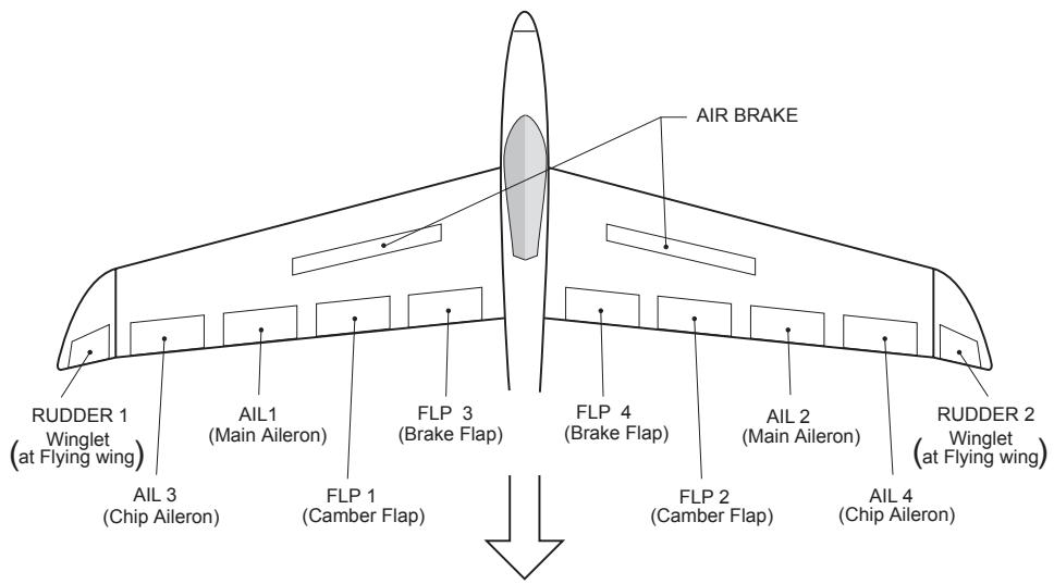
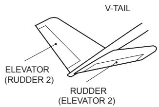
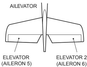
AIL Differential
[Airplane/glider, 2 ailerons or more]
The left and right ailerons differential can be adjusted independently. The differential rate can also be adjusted according to the flying state by setting a fine tuning VR.
- A fine tuning curve can be set. Note: Aileron up/down setting (%) reset is +100% when reset when setting is +, and - 100% when reset when setting is -. Left and right mixing causes + and - to change. Before flying, confirm the direction of operation.
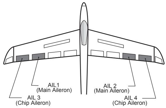
- Touch the [All Differential] button in the Model Menu to call the setup screen shown below.
*The display screen is an example. The actual screen depends on the Model Type.
- Calls the AFR screen directly when adjusting aileron operation AFR.
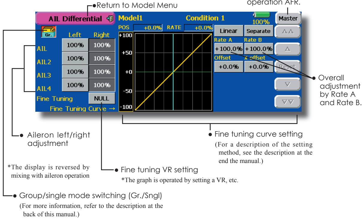
Setting method
- Touch the aileron (AIL) 1~4 left (or right) button, and adjust the aileron angles when the stick is moved to the left (or right) end.
*The aileron AFR screen can be directly called from the AIL Differential setup screen. ([Master] button)
- When setting the fine tuning VR, touch the "NULL" button to call the
screen, and then select the fine tuning VR.
The fine tuning rate can be set by curve.
Flap setting
[Corresponding model type]: Airplane/glider, 2 flaps or more
The up/down travel of each flap (camber flaps: FLP1/2, brake flaps: FLP3/4) can be adjusted independently at each servo according to the wing type.
- The operation reference point of each flap can be offset
The camber flaps of a 4-flap model can be mixed with the brake flaps. (Brake FLP to camber FLP)
- An ON/OFF switch can be set.
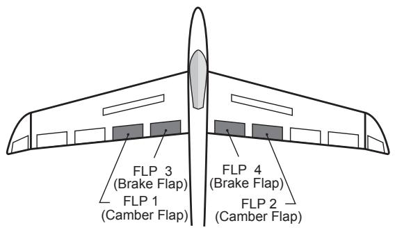
- Touch the [Flap Setting] button in the Model Menu to call the setup screen shown below.
*The display screen is an example. The actual screen depends on the model type.
- Group/single mode switching (Gr./Sngl)
(For more information, see the description at the back of this manual.)
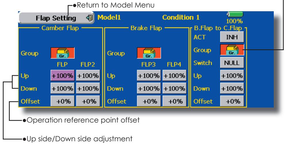
Setting method
- Touch the flap (FLP) 1 4 Up or Down button according to the wing type and adjust the travel independently.
- To offset the operation reference point of each flap, touch the corresponding Offset button. Use the adjustment buttons displayed on the screen to offset the reference point.
- When using Brake FLP to Camber FLP mixing, touch the ACT button and set the function to ACT (ON). When setting a switch, touch the [NULL] button of the switch to call the
screen, and then select the switch and set its ON direction. (Always ON at "NULL" setting)
(For a description of the switch selection method, see the description at the back of this manual.)
AIL to Camber FLP
[Corresponding model type]: Airplane/glider, 2 ailerons + 2 flaps or more
This mixing operates the camber flaps (FLP1/2) in the aileron mode. When the aileron stick is manipulated, the ailerons and camber flaps perform aileron operation simultaneously and the operation characteristic of the roll axis is improved.
- The aileron left/right mixing rate of each flap servo can be fine-tuned.
- A mixing curve can be set.
- An ON/OFF switch can be set.
- Linking is possible: Links this mixing to other mixings.
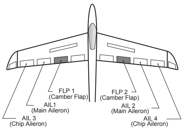
- Touch the [AIL to Camber FLP] button in the Mode Menu to call the setup screen shown below.
*The display screen is an example. The actual screen depends on the model type.

Setting method
- Touch the ACT button and set the function to ACT (ON).
- When setting a switch, touch the [NULL] button of the switch to call the
screen, and then select the switch and set its ON direction. (Always ON at "NULL" setting) (For a description of the switch selection method, see the description at the back of this manual.) - Touch the left or right button of each flap servo, and adjust the mixing rate with the adjustment buttons.
*When the mixing direction is reversed by the linkage, adjustments can be made by changing the mixing rate polarity.
- A mixing curve can be set. (For a description of the mixing curve setting method, see the description at the back of this manual.)
- To set linking, touch the Link button and set it to ON.
AIL to Brake FLP
[Corresponding model type]: Airplane/glider, 4 flaps or more
This mixing operates the brake flaps (FLP3/4) in the aileron mode. When the aileron stick is manipulated, the aileron and brake flaps perform the aileron operation simultaneously and the operation characteristic of the roll axis is improved.
- The aileron left and right mixing rates can be adjusted for each flap servo.
- A mixing curve can be set.
- Mixing during flight can be turned ON/OFF by setting a stick. (Always ON at NULL setting)
- Linking can be set: Links this mixing to other mixings.
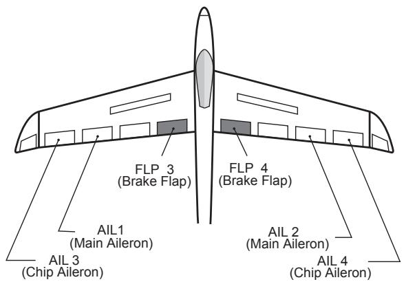
- Touch the [AIL to Brake FLP] button in the Model Menu to call the setup screen shown below.
*The display screen is an example. The actual screen depends on the model type.
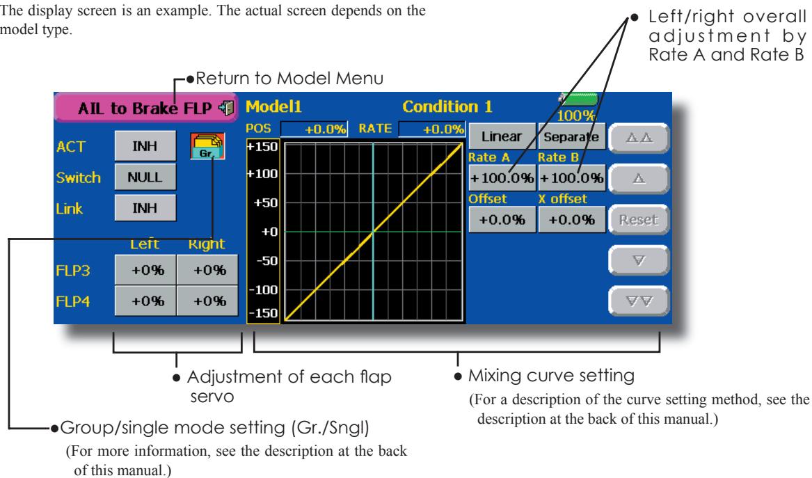
- Setting method
- Touch the ACT button and set the function to ACT (ON).
- When setting a switch, touch the [NULL] button of the switch to call the
screen, and then select the switch and set its ON direction. (Always ON at "NULL" setting) (For a description of the switch selection method, see the description at the back of this manual.) - Touch the left or right button of each flap servo, and adjust the mixing rate with the adjustment buttons.
*When the mixing direction is reversed by the linkage, adjustments can be made by reversing the mixing rate polarity.
- A mixing curve can be set.
(For a description of the curve setting method, see the description at the back of this manual.)
- To set linking, touch the Link button and set it to ON.
Use this mixing when you want to mix the rudders with aileron operation.
- A mixing curve can be set.
- Mixing during flight can be turned ON/OFF by setting a switch. (Always ON at NULL setting)
- The mixing rate can be fine-tuned by setting a VR.
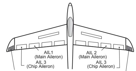
RUDDER 1 Winglet (at Flying wing)
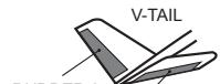
R 2 RUDDER
RUDDER
- Touch the [AIL to RUD] button in the Model Menu to call the setup screen shown below.
*The display screen is an example. The actual screen depends on the model.
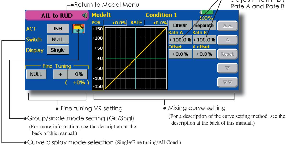
Setting method
- Touch the ACT button and set the function to ACT (ON).
- When setting a switch, touch the [NULL] button of the switch to call the
screen, and then select the switch and set its ON direction. (Always ON at "NULL" setting)
(For a description of the switch selection method, see the description at the back of this manual.)
- When setting a VR, touch the Fine Tuning "NULL" button to call the
screen, and then select the VR. The adjustment rate and direction can be set. The VR operation mode can also be selected. - A mixing curve can be set. (For a description of the curve setting method, see the description at the back of this manual.)
- The curve display mode can be changed. Single : Displays the mixing curve only Fine tuning : Displays the mixing rate of the fine tuning VR
All Cond.: Displays the mixing curve of all the conditions. (When conditions are set)
Fine tuning VR setting
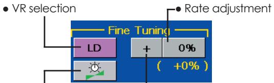
Operation mode selection L-Adjustment direction *Displayed at VR setting
[Operation modes]
![FUTABA 14MZ - [Operation modes] - 1](/content/2025/01/163546/images/e79e82b17b40a1f61d2215438f317e7262e6e27b2901f7052dfbfe5ffae4a1c1.jpg)
Mixing rate 0% at center of VR When the VR is turned counterclockwise and clockwise, the mixing rate increases and decreases, respectively.
![FUTABA 14MZ - [Operation modes] - 2](/content/2025/01/163546/images/0a4991c3ca8f6546dc6422999c7a968087431470db65be4d823236b3e4eb7b7a.jpg)
Mixing rate 0% at left end of VR When the VR is turned, the mixing rate increases.
![FUTABA 14MZ - [Operation modes] - 3](/content/2025/01/163546/images/7e81f05684bff77213937d604d96af27c7e16c669aa753aad13b8cec5fdb5931.jpg)
Mixing rate 0% at right end of VR. When the VR is turned, the mixing rate increases.
![FUTABA 14MZ - [Operation modes] - 4](/content/2025/01/163546/images/bf75dd0dfff5a918ac5c33ae5e34d624604e3ea483dc70946f8359c1ed3ce129.jpg)
When the VR is turned to the left or right of the neutral position, the mixing rate increases.
This mixing is used when you want to mix the elevators with airbrake (spoiler) operation. It raises the elevators to correct for drooping of the nose during airbrake operation.
*This function does not operate when airbrake is not assigned at the Function menu in the Linkage Menu.
- The Rate 1 side/Rate 2 side mixing rate with the elevator servos can be adjusted.
- A mixing curve can be set.
- Mixing during flight can be turned ON/OFF by setting a switch. (Always ON at NULL setting)
- The mixing rate can be fine-tuned by setting a VR.
![FUTABA 14MZ - [Operation modes] - 5](/content/2025/01/163546/images/0cd8bd60878910fe7f8c56db1ec26baa8d97dac533b3aa1021d45938b67e953f.jpg)
![FUTABA 14MZ - [Operation modes] - 6](/content/2025/01/163546/images/06b5e0f4e68113ae8fb9efbfe9f9dc6dcc25b7e8a2dd8df7834d99afc3148874.jpg)
![FUTABA 14MZ - [Operation modes] - 7](/content/2025/01/163546/images/6135138fe84218b471f9dcaa8275d0662ebf0f5b8d39707b786201cdef0a81f4.jpg)
Setting method
- Touch the "INH" button and set the function to ACT (ON).
- When setting a switch, touch the [NULL] button to call the
screen, and then select the switch and set its ON direction. (Always ON at "NULL" setting)
(For a description of the switch selection method, see the description at the back of this manual.)
- When setting a VR, touch the Fine tuning "NULL" button to call the
screen, and then select the VR. The adjustment rate and direction can be set. The VR operation mode can also be set.
(For a description of the fine tuning VR setting method, see the description at the back of this manual.)
- A mixing curve can be set. (For a description of the curve setting method, see the description at the back of this manual.)
- The curve display mode can be set.
Single : Displays the mixing curve only
Fine tuning : Displays the adjustment rate of the fine tuning VR
All Cond.: Displays the mixing curve of all the conditions. (When conditions are set)
This function is used when you want to mix the ailerons with rudder operation. It is used when rudder is applied during roll maneuvers, knife edge, etc. of stunt planes. It can be used to bank scale models, large models, etc. like a full size plane.
- A mixing curve can be set.
- Mixing during flight can be turned ON/OFF by setting a switch. (Always ON at [NULL] setting)
-
The rate of correction rudder can be memorized by using the memory function. This is convenient when setting a mixing curve. When memory operation (switch operation) is performed in the memory mode with correction rudder applied, the switch operation position at that time is displayed
-
Touch the [RUD to AIL] button in the Model Menu to call the setup screen shown below.
on the mixing curve. When the memory mode is exited, the memorized points are automatically reflected on the curve. (When the memory function is used, "Line" type curve is automatically selected.)
- Linking can be set: Links this mixing to other mixings.
- The mixing rate can be fine-tune by setting a VR.
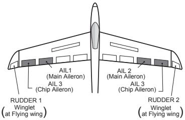
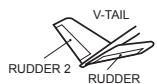
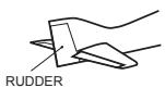
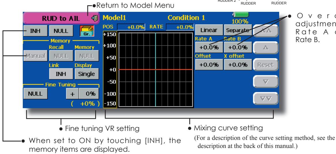
Setting method
- Touch the "INH" button and set the function to ACT (ON).
- When setting a switch, touch the [NULL] button to call the
screen, and then select the switch and set its ON direction. (Always ON at "NULL" setting) (For a description of the switch selection method see the description at the back of this manual.) - When setting a VR, touch the Fine tuning "NULL" button to call the
screen and then select the VR. The adjustment rate and adjustment direction can be set.. The VR operation mode can also be set. (For a description of the fine tuning VR setting method, see the description at the back of this manual.) - A mixing curve can be set. (For a description of the curve setting method, see the description at the back of this manual.)
- The curve display mode can be changed. Single : Displays the mixing curve only Fine tuning : Displays the adjustment rate of the fine tuning VR
All Cond.: Displays the mixing curve of all the conditions. (When conditions are set)
- When linking: Touch the Link button and set it to ON.
Memory function usage method
(Example) Using the memory function with an F3A airplane (knife edge correction)
*When call switch [SW-A] and memory switch [SW-H] were set
[Memory function operation]
- Memory function mode: [Manual] [Memory]
- When the memory switch (SW-H) was set to ON while performing aileron correction when rudder was applied at knife edge, the point position at that time is memorized. Perform memorization while changing the left and right stick positions.
- To recall the memorized positions, set [SW-A] to ON. The memorized correction rate is reflected on the curve, and operation is simultaneously set.
Note: When memorized from manual before flight, be sure that the memory SW is not accidentally set to ON and incorrect mixing setting is not applied when taxiing, starting the engine, etc.
Camber Mix
[Corresponding model type]: Airplane/glider, 2 ailerons or more
This function adjusts the AFR (D/R) rate of camber operation which operates the wing camber (ailerons, camber flaps, brake flaps) in the negative and positive directions. The aileron, flap, and elevator rates can also be adjusted independently by curve, and attitude changes caused by camber operation can be corrected.
*Initial setting assigns camber operation to side lever LST.
-
The up/down side rates of the aileron, flap, and elevator servos can be adjusted by curve. When the mixing direction is reversed by the linkage, adjustments can be made by changing the mixing rate polarity.
-
Mixing during flight can be turned ON/OFF by setting a switch. (Always ON at NULL setting)
- A delay can be set for each condition. A cut switch which can turn OFF the delay function can be set.
-
The speed of the aileron, flap, and elevator servos can be set. (IN side/OUT side)
-
Touch the [Camber Mix] button in the Model Menu to call the setup screen shown below.
*The display screen is an example. The actual screen depends on the model type.)
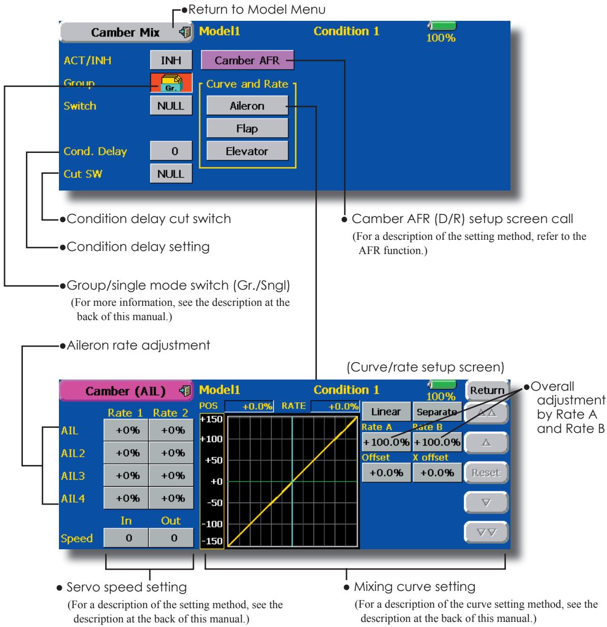
Setting method
- Touch the "INH" button and set the function to ACT (ON).
- When setting a switch, touch the [NULL] button to call the
screen, and then select the switch and set its ON direction. (Always ON at "NULL" setting)
(For a description of the switch selection method, see the description at the back of this manual.)
-
When setting a condition delay, touch the Condition Delay button and set the delay with the adjustment buttons which appear on the screen. The VR operation mode can also be set. (For a description of condition delay, see the description at the back of this manual.)
-
Camber AFR(D/R) screen call
- Touch the Camber AFR button to call the setup screen. (For a description of the setup method, see the description at the back of this manual.)
(Curve/rate setup screen)
- The curve and rate are adjusted by calling the aileron, flap, and elevator curve/rate screens. The rate and curve of each servo can be set by calling each screen. (For a description of the curve setting method, see the description at the back of this manual.)
The servo speed can also be adjusted.
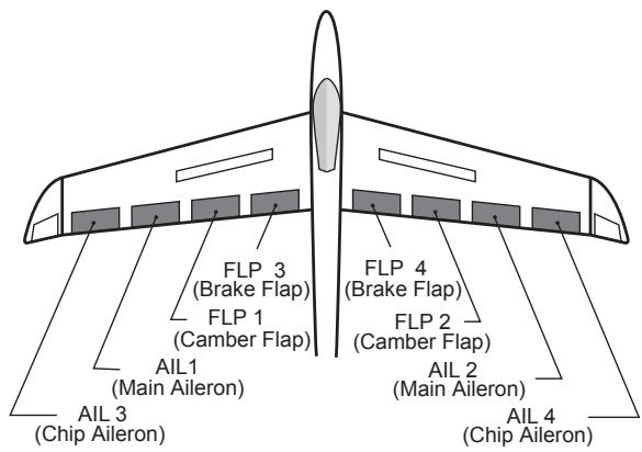
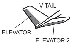
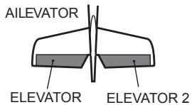
ELE to Camber
[Corresponding model type]: Airplane/glider, 2 ailerons or more
This function is used when you want to mix the camber flaps with elevator operation. When mixing is used so that the flaps are lowered by up elevator, lift can be increased.
- A mixing curve can be set.
- Mixing during flight can be turned ON/OFF by setting a switch. (Always ON at NULL setting)
- The mixing rate can be fine-tuned by setting a VR.
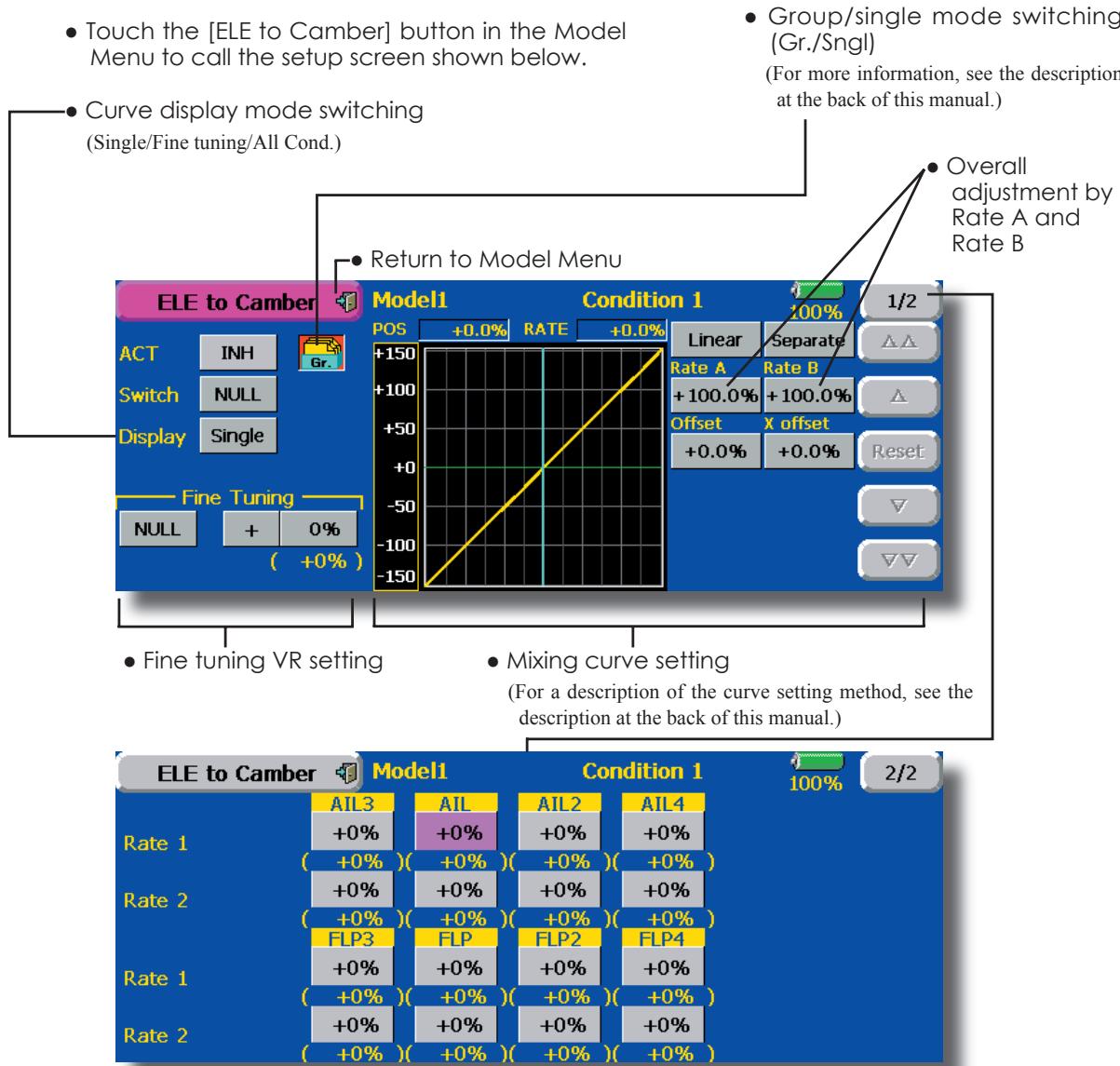
(Ailerons and flaps rate adjustment screen)
Setting method
- Touch the ACT button and set the function to ACT(ON).
- When setting a switch, touch the [NULL] button of the switch to call the
screen, and then select the switch and set its ON direction. (Always ON at "NULL" setting.) -
When setting a VR, touch the Fine tuning "NULL" button to call the
screen, and then select the VR. The adjustment rate and adjustment direction can be set. The VR operation mode can also be selected. -
A mixing curve can also be set. (For a description of the curve setting method, see the description at the back of this manual.)
- The curve display mode can be changed. Single : Displays the mixing curve only Fine tuning : Displays the fine tuning VR adjustment rate
All Cond.: Displays the mixing curve of all the conditions (When conditions are set)
Camber FLP to ELE
[Corresponding model type]: Airplane/glider, 2 ailerons + 1 flap or more
This mixing is used to correct changes (elevator direction) generated when the camber flaps (speed flaps) are used.
- The elevator servos up side/down side rate can be adjusted. When the mixing direction is reversed by the linkage, adjustments can be made by changing the mixing rate polarity.
- A mixing curve can be set.
- Mixing during flight can be turned ON/OFF by setting a switch. (Always ON at NULL setting)
- The mixing rate can be fine-tuned by setting a VR.
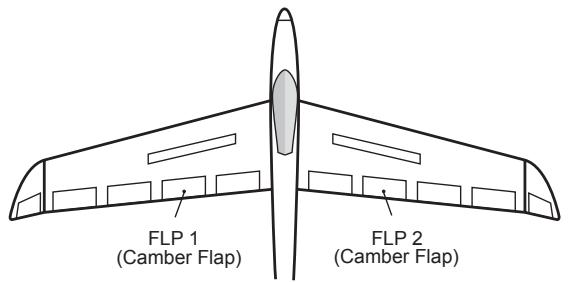
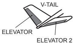
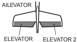
-
Touch the [Camber FLP to ELE] button in the Model Menu to call the setup screen shown below.
*The display screen is an example. The actual screen depends on the model type. -
Group/single mode switching (Gr./Sngl)
(For more information, see the description at the back of this manual.)

Setting method
- Touch the ACT button and set the function to ACT(ON).
- When setting a switch, touch the switch button to call the
screen, and then select the switch and set its ON direction. (Always ON at "NULL" setting)
(For a description of the switch setting method, see the description at the back of the manual.)
- Touch the elevator servos left and right buttons and adjust the mixing rate with the adjustment buttons displayed on the screen.
*When the mixing direction is reversed by the linkage, adjustments can be made by changing the mixing rate polarity.
- When setting a VR, touch the Fine tuning "NULL" button to call the
screen, and then select the VR.
The VR operation mode can be selected. - A mixing curve can be set. (For a description of the curve setting method, see the description at the back of this manual.)
The curve operation mode can be changed.
Single : Displays only the mixing curveFine Tuning : Displays the adjustment rate of theine tuning VR
All Cond. : Displays the mixing curve of all the conditions (when conditions are set)
This function allows powerful brake operation by simultaneously raising the left and right ailerons and lowering the flaps (camber flap, brake flap).
This setting will allow the ailerons to be raised while the flaps are simultaneously lowered. Butterfly (Crow) produces an extremely efficient landing configuration by accomplishing the following:
- Slow the aircraft's velocity.
- Provide washout at the wing tips to reduce the tendency to tip stall.
-
Create more lift toward the center of the wing allowing it to fly at a slower speed
-
Touch the [Butterfly] button in the Model Menu to call the setup screen shown below.
(The display screen is an example. The actual screen depends on the model type. The screen shown below is for 4 ailerons and 4 flaps.)
- Touch the ACT button and set the function to ACT (ON).
- When setting a switch, touch the SWITCH [NULL] button to call the
screen, and then select the switch and set its ON direction.
When offsetting the butterfly operation reference point, operate to the point you want to change and then touch the Offset button. The reference point displays 0% . When [Yes] is touched, the reference point is changed.
- Mixing during flight can be turned ON/OFF by setting a switch. (Always ON at NULL setting)
- The butterfly operation reference point can be offset. When the Offset button is touched when operated to the position to be changed, the reference point is offset. If the reference point is offset too much, unexpected operation may be performed.
- The ailerons, flaps, and elevators operation speed can be adjusted. (IN side/OUT side)
- A delay can be set for each condition. A cut switch which can turn OFF the delay function can also be set.
- The differential rate can be adjusted.
*When servo binding occurs when setting the ailerons and flaps in butterfly mixing, use the AFR function to adjust the rudder angle.
Group/single mode switching (Gr./Sngl)
(For more information, see the description at the back of this manual.)
-
Touch the Mixing Rate All and FLP buttons and adjust the mixing rates.
-
Aileron and flap servos speed setting
(For a description of the setting method, see the description at the back of this manual.)
- Condition delay setting and cut switch setting
(For a description of the setting method, see the description at the back of this manual.)
Differential rate adjustment
- Calls the Butterfly AFR (D/R) setup screen
(For a description of the setting method, see the description at the back of this manual.)
- Touch the ELE correction rate buttons and adjust the rates with the adjustment buttons displayed on the screen.
([ELE Setup] screen)
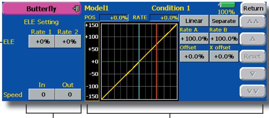
Servo speed setting (For a description of the setting method, see the description at the back of this manual.)
- Mixing curve setting (For a description of the curve setting method, see the description at the back of this manual.)
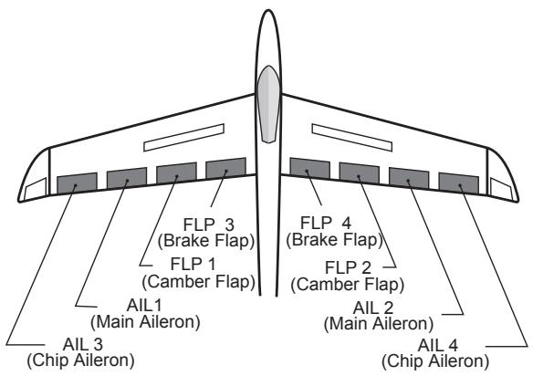
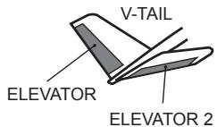
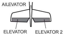
These functions call the ailerons, elevators, and flaps (camber flaps, brake flaps) trim offset rates preset according to the flight state.
The amount of ailerons, elevator, and flaps (camber flap, brake flap) trim offset can be set to a switch.
As an example Trim Mix 1 can be set up for launching, with speed flaps and ailerons dropped, and a slight amount of up elevator. Trim mix 2 can be used for high speed flying, with both ailerons and speed flaps reflexed slightly, and a bit of down elevator.
The trim functions can be activated during flight by setting a switch. To prevent sudden trim changes when switching flight conditions, a delay can be set to provide a smooth transition between the two. Trim Mix 2 will have priority over Trim Mix 1.
Example
- Touch the ACT button and set the trim mix function to [ON].
*When separating the settings for each condition, touch the group mode button and set it to [Sngl]. - Select the ON/OFF switch.
- Select the [Manual] or [Auto] mode. In the [Auto] mode, also select an auto SW. This switch can be linked to a stick, etc.
In: The operation speed at switch ON can be set.
Out: The return speed at switch OFF can be set.
The offset rate can be varied in the Fine Tuning numeric range set at screen [1/2] by VR, etc. selection.
When flight conditions are set, the operation speed can be set for each condition. Condition delay operation can be interrupted and each rudder quickly returned to its original position by selecting a cut switch.
- Touch the [Trim Mix 1] button in the Model Menu to call the setup screen shown below.
(The display screen is an example. The actual screen depends on the model type. The screen shown below is for 4 ailerons and 4 flaps.)
(Touch the [1/2] button to switch to page 2.)
- Touch the ACT button and set the function to ACT (ON).
- When setting a switch, touch the Switch button to call the
screen, and then select the switch and set its ON direction. (Always ON at "NULL" setting)
(For a description of the switch selection method, see the description at the back of this manual.)
- The ailerons, flaps, and elevators offset rate can be adjusted.
Touch the corresponding button and adjust the rate with the adjustment buttons displayed on the screen.
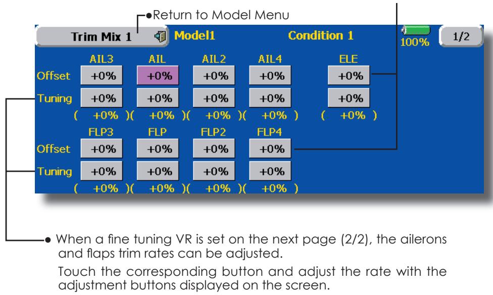
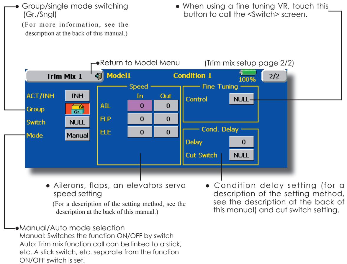
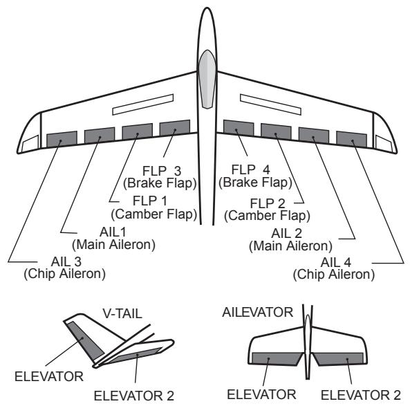
This function is used when an air brake is necessary when landing or diving, etc.
The preset elevators and flaps (camber flap, brake flap) offset amount can be activated by a switch.
The offset amount of the aileron, elevator, and flap servos can be adjusted as needed. Also the speed of the aileron, elevator, and flap servos can be adjusted. (IN side/OUT side) A delay can be set for each condition, and a Cut switch which will turn OFF the delay can be chosen. Trim amounts can be fine-tuned by setting a VR You can also set the Auto Mode, which will link Airbrake to a stick, switch, or dial. A separate stick switch or dial can also be set as the ON/OFF switch.
Setting example for F3A and other flaperon specifications
(When 2 ailerons model type selected)
(Page 1/2)
Offset rate:
AIL: [-35 -45%] , AIL2: [-35 -45%] , ELE: [+5|7%]
Note: The input numerics are examples. Adjust the travel to match the fuselage.
(Screen 2/2)
ACT: [ON]
Group: [Sngl]
Switch: [SC-C]
Mode: [Manual]
- Touch the [Airbrake] button in the Model Menu to call the setup screen shown below. (The display screen is an example. The actual screen depends on the model type. The screen shown below is for 4 ailerons and 4 flaps.) (Touch the [1/2] button to switch to page 2.)
- Touch the ACT button and set the function to ACT(ON).
- When setting a switch, touch the Switch button to call the
screen, and then select the switch and set its ON direction. (Always ON at "NULL" setting)
(For a description of the switch selection method, see the description at the back of this manual.)
- The aileron, flap, and elevator offset rates can be adjusted.
Touch the corresponding button and adjust the rate with the adjustment buttons displayed on the screen.
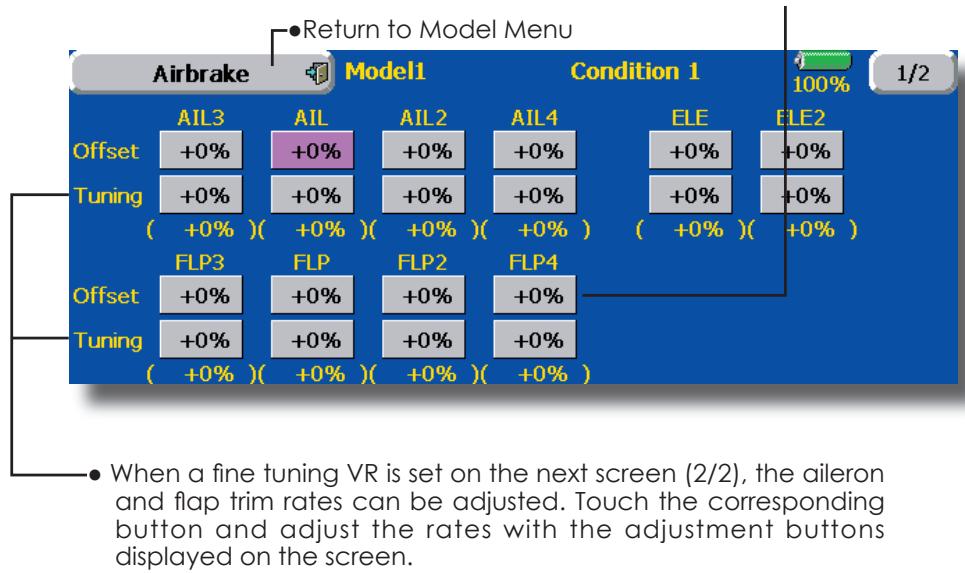
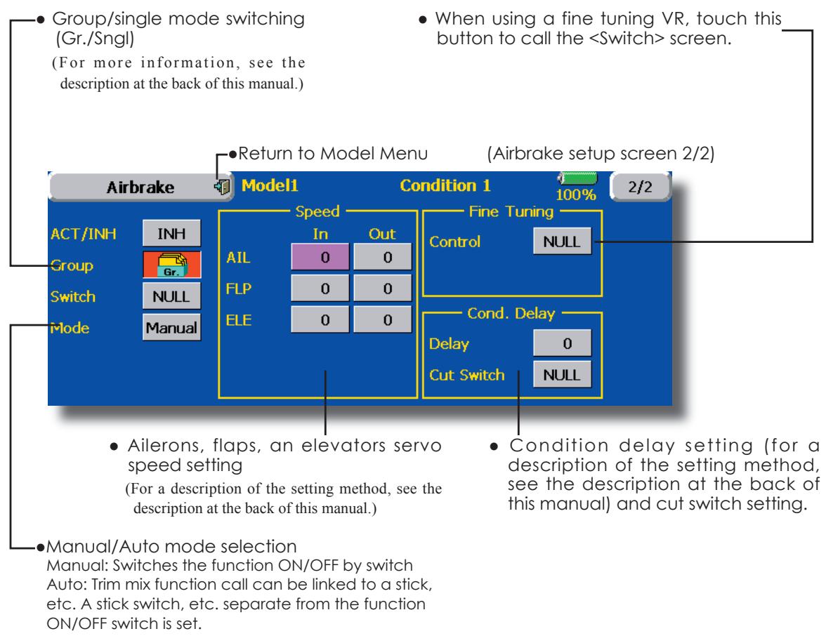
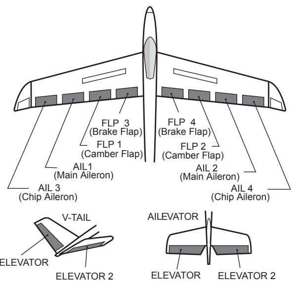
This function is used when a GYA Series gyro is used to stabilize the fuselage attitude. The sensitivity and operation mode (Normal mode/GY mode) can be switched with a switch.
- Three rates (Rate 1/Rate 2/Rate 3) can be switched.
- Up to 3 axes (Gyro/Gyro 2/Gyro 3) can be simultaneously controlled.
*Initial setting does not assign a sensitivity channel. Use the
Function menu of the Linkage Menu to assign the sensitivity channel (Gyro/Gyro2/Gyro3) used to a vacant channel beforehand.
Set [ACT] and [Trim] other than Function to [NULL].
-
Touch the [Gyro] button in the Model Menu to call the setup screen shown below.
-
Group/single mode switching (Gr./Sngl)
(For more information, see the description at the back of this manual.)
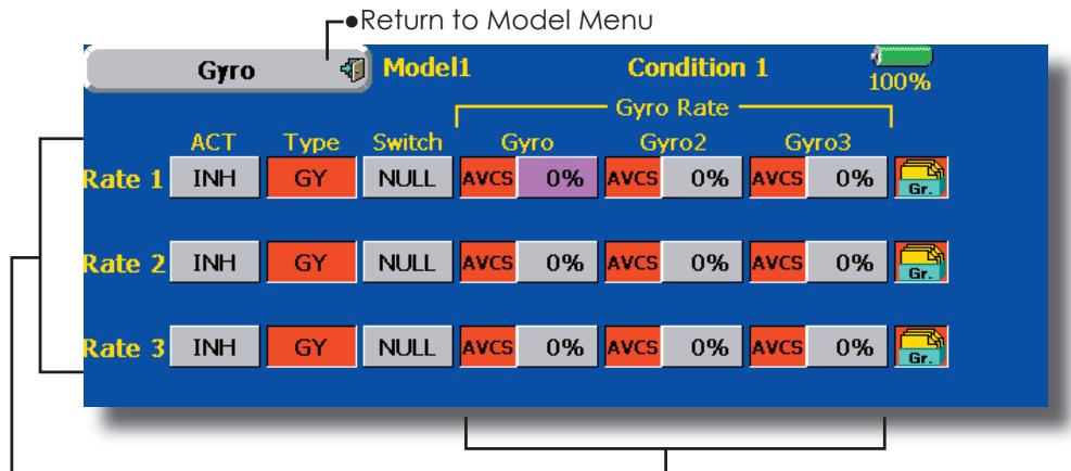
-
The operation mode (AVCS/NOR) and sensitivity of the 3 axes Gyro/Gyro2/Gyro3 can be set.
-
Three rates (Rate 1/Rate 2/Rate 3) can be used.
-
Touch the ACT button of the rate to be used, and set the function to ACT ([ON] or [OFF]).
- When a Futaba GYA gyro is used, when [GY] type is s elected, the sensitivity set value is directly read in both the AVCS and NOR modes.
- When setting a switch, touch the switch button to call the
screen, and then select the switch and set its ON direction.
(For a description of the switch selection method, see the description at the end of this manual.)
(Example) Setting 3 axes using a GYA351 and GYA352 (2 axes gyro)
- Wing type: Aileron 2 servos mounted fuselage selected
- Set Gyro 1 (GYA351): CH7, Gyro 2 (GYA352): CH8, Gyro 3 (GYA352): CH9 at the Function menu of the Linkage Menu.
- Rate 1 [OFF][GY][SW-E][NOR][60%][NOR][60%][NOR][60&][Gr] Rate 2 [INH][GY][NULL][AVCS][0%][AVCS][0%][AVCS][0%][Gr] Rate 3 [OFF][GY][SE-E][AVCS][60%][AVCS][60%][AVCS][60%][Gr]
*When separating the conditions, set to [Sngl].
*Set so that Rate 1 is turned on at the back position of switch E and Rate 3 is turned ON at the front position.
Since switch E is turned OFF at the center, Rate 2 remains [INH].
V-tail
[Corresponding model type]: Airplane/glider, V-tail
This function let's you adjust for left and right rudder angle changes at elevator and rudder operation of a V-tail airplane.
V-tail is when 2 servos are used together to control rudder movement as Elevators. In addition to each rudder side moving up and down together, each side moves in opposite directions when moving as Elevators. On a V-tail, this is also known as a Ruddervator, as they can serve the same purpose.
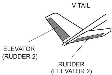
-
Touch the [V-tail] button in the Model Menu to call the setup screen shown below.
-
Group/single mode switching (Gr./Sngl)
(For more information, see the description at the back of this manual.)
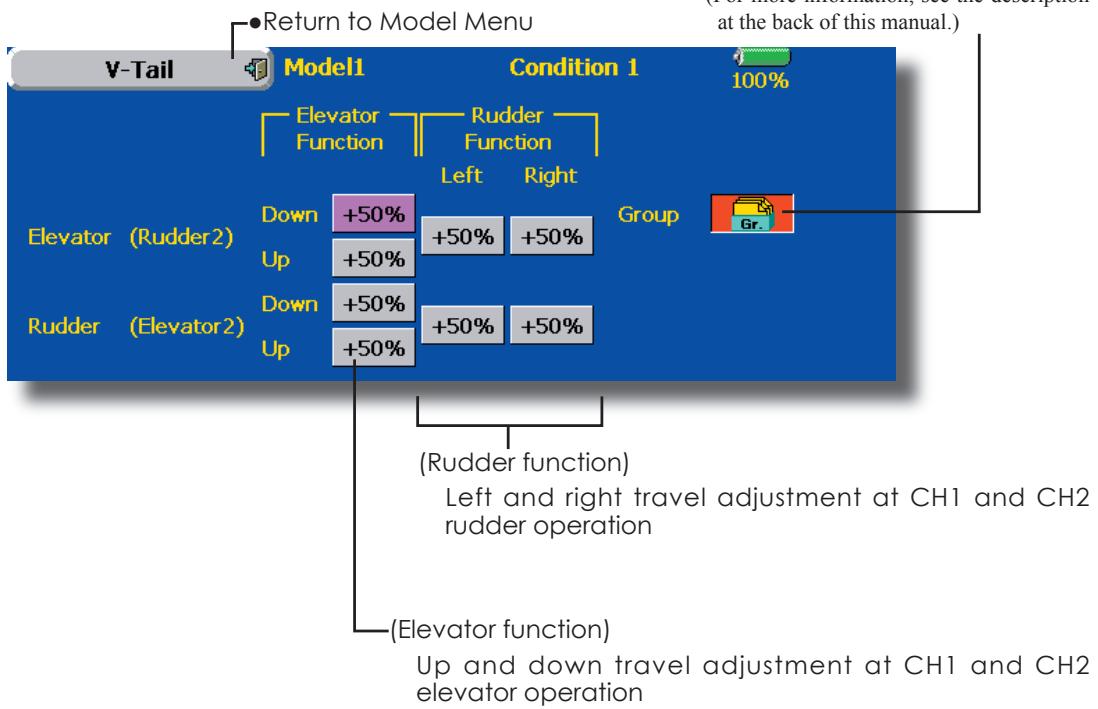
Alevator
[Corresponding model type]: Airplane/glider, V-Tail
(Effective only when 2 servos used at the elevators)
This function improves the operating performance of the roll axis by operating the elevators as ailerons.
Ailevator is where each elevator in a standard (conventional) or v-tail moves independently, like ailerons on a wing. In addition to each elevator side moving up and down together, each side moves in opposite directions when moving as an Ailevator. On a V-tail, this is also known as a Ruddervator, as they can serve the same purpose. Typically, both Ailevator and ailerons are coupled together to maximize roll performance, especially on larger wingspan planes.
Note: Select Ailevator as the Model Type at the Model
Type screen. This changes the output channel. Check
the Function menu.
-
Touch the [AIL] button in the Model Menu to call the setup screen shown below.
-
Group/single mode switching (Gr./Sngl)
(For more information, see the description at the back of this manual.)
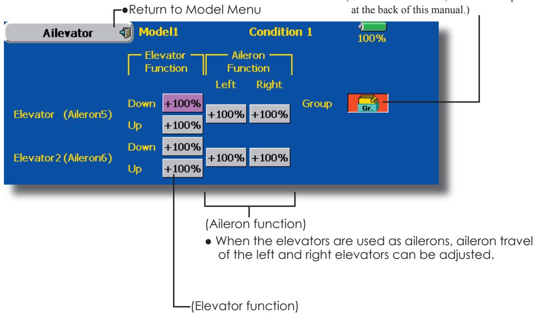
- The up and down rate of the left and right elevators when the elevator stick is manipulated can be individually adjusted.
Winglet
[Corresponding model type]: Airplane/glider, winglet
This function adjusts the rubber left and right rudder angle of winglet specifications fuselages.
Winglets are used to improve the efficiency of aircraft lowering the lift-induced drag caused by wingtip vortices. The winglet is a vertical or angled extension at the tips of each wing.
Winglets work by increasing the effective aspect ratio wing without adding greatly to the structural stress and hence necessary weight of its structure - an extension of wing span would also permit lowering of induced drag, though it would cause parasitic drag and would require boosting the strength of the wing and hence its weight - there would come a point at which no overall useful saving would be made. A winglet helps to solve this by effectively increasing the aspect ratio without adding to the span of the wing.
![FUTABA 14MZ - [Corresponding model type]: Airplane/glider, winglet - 1](/content/2025/01/163546/images/1c6be4790e6f94164f35093c2671106d86bd9cce09af4dac19bccfabe0b6e603.jpg)
-
Touch the [Winglet] button in the Model Menu to call the setup screen shown below.
-
Group/single mode switching (Gr./Sngl) (For more information, see the description at the back of this manual.)
![FUTABA 14MZ - [Corresponding model type]: Airplane/glider, winglet - 2](/content/2025/01/163546/images/2a7934182ef5db1d2848eeb71990f4d92e1d3600eee818f7f794bd64d6e4f160.jpg)
- The travel at rudder stick left and right operation can be individually set.
This function lets you set the operation speed when the motor of a F5B or other EP glider is started by switch. The operation speed can be set in 2 ranges of slow speed flight and high speed flight (Speed 1/Speed 2). This function can also be operated as a safety function by setting 2 switches.
- The In side and Out side operating speeds can be adjusted independently in 2 ranges (Speed 1/Speed 2).
- The boundary between the 2 ranges can be set. (From Speed 1 to Speed 2)
- The set operation speed operation can be activated at initial operation only. (1 time operation) However, operation can be repeated
by setting the switch to OFF before operation is finished. When you want to reset 1 time operation, set the ACT button to [INH] and then reset it to [ON].
- The motor (CH3) is controlled by SW-G. (Initial setting) When changing the switch or stick which controls the motor, first change Function of the Linkage Menu.
Note: When using this function, always check initial operation with the propeller removed.
- Touch the [Motor] button in the Model Menu to call the setup screen shown below.
![FUTABA 14MZ - [Corresponding model type]: Airplane/glider, winglet - 3](/content/2025/01/163546/images/73e6321e1420f8894bc380fa5ee60121dd114902e7ca706e7252e0117fa26db3.jpg)
Operation
Touch the button and set the function to ON.
- Group/single mode switching (Gr./Sngl)
(For more information, see the description at the back of this manual.)
- Switch
A switch that turns the function itself ON/OFF can be selected.
- Motor off
[Yes] and [No] are displayed by touching the Motor Off button when [SW-G] is in the motor OFF position. When [Yes] is touched, the direction of the motor switch is memorized. The screen graph display ON direction also changes.
Operation
Touch the button and set the function to ON.
- When you want to set the "One time mode", touch the button and set the mode to [ON].
- Speed 1 to 2
The Speed 1 and Speed 2 region boundary can be changed,
Operation speed adjustment
The speed when Speed 1 and Speed 2 are ON (In) and OFF (Out) can be adjusted.
Notes
- First decide the motor OFF point, and then set the speed. When you want to reset the motor OFF point, also reset the speed.
- We recommend that Motor OFF be set in combination with F/S.
- Set the basic operation direction with the Reverse function to match the amp used.
- Always set the Motor OFF position.
RUD to ELE
[Corresponding model type]: Airplane, general
This function is used when you want to mix elevator operation with rudder operation. It is used to correct undesirable tendencies when rudder is applied in roll maneuvers, knife edge, etc. of stunt planes.
- A mixing curve can be set.
- Mixing during flight can be turned ON/OFF by setting a switch. (Always ON at NULL setting)
- The amount of correction rudder can be memorized by using the Memory function. This is
convenient at mixing curve setting. When memory operation (switch operation) is performed with correction rudder applied in the Memory Mode, the stick position at that time is displayed on the mixing curve. The point is automatically reflected in the curve. (When the Memory function is used, "Line" is automatically selected as the curve type.)
- Link can be set: Links this mixing to other mixings.
-
The mixing rate can be fine-tuned by setting a VR. (Fine tuning)
-
Touch the [RUD to ELE] button in the Model Menu to call the setup screen shown below.
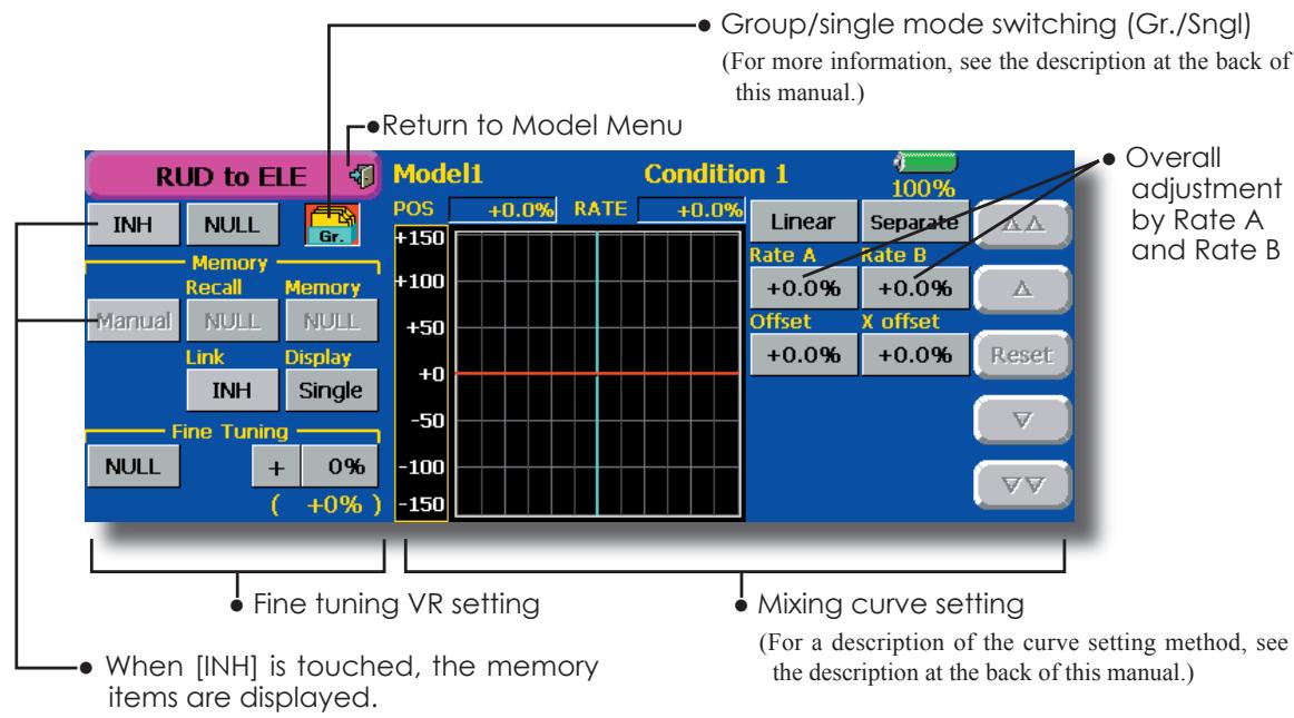
Setting method
- Touch the "INH" button, and set the function to ACT(ON).
- When setting a switch, touch the "NULL" button to call the
screen, and then select the switch and set its ON direction. (Always ON at "NULL" setting) (For a description of the switch setting method, see the description at the back of this manual.) - When setting a VR, touch the Fine Tuning "NULL" button to call the
screen, and then select the VR. The fine tuning rate and adjustment direction can be set. The VR operation mode can also be set. (For a description of the fine tuning VR setting method, see the description at the back of this manual.) - The curve display mode can be changed. Single : Displays the mixing curve only Fine Tuning : Displays the fine tuning rate of the fine tuning VR All Cond. : Displays the mixing curve of all the conditions (When conditions are set)
- When setting Link, touch the Link button and set it to ON.
Memory function usage method
(Example) Using the memory function with an F3A airplane (knife edge correction)
*When call switch [SW-A] and memory switch [SW-H] were set
[Memory function operation]
- Memory function mode: [Manual] [Memory]
- When the memory switch (SW-H) is set to ON while performing elevator correction when rudder was applied at knife edge, the point position at that time is memorized. Memorization is performed while changing the left and right stick positions.
- To recall the memorized positions, set [SW-A] to ON. The memorized correction rate is reflected on the curve, and operation is simultaneously set.
Note: When memorized from manual before flight, be sure that the memory SW is not accidentally set to ON and incorrect mixing setting is not applied when taxiing, starting the engine, etc.
This function selects the switch and rate adjustment of each rudder, (ailerons, elevators, or flaps) when a snap roll is performed.
- Four snap roll directions can be set. (Right/up, right/down, left/up, left/down)
- Operation mode: When [Master] mode is selected, the Snap Roll function is turned ON/OFF by master switch in the state in which the direction switch was switched to the direction in which you want to snap roll. When [Single] mode is selected, snap roll in each direction can be executed by means of independent switches.
- A safety switch can be set. As a safety measure, the switch can be set so that snap roll is not executed when, for instance, the landing gear is lowered, even if the switch is turned on accidentally. The snap roll switch is activated only when the safety switch is ON.
- The operation speed of the aileron, elevator, and flap servos can be adjusted for each snap roll direction. (In side/Out side) (Page 2/2)
(Example) Setting example for F3A
Mode: [Master]
- Safety SW: [SW-G] (Safety measure)
- Master SW: [SW-H] (Main switch for executing snap roll)
- Direction switches:
*The snap roll up side left and right and down side left and right direction switches are selected here.
Right/Up: OFF [SW-D]
Right/Down: OFF [SW-D]
Left/Up: OFF [SW-A]
Left/Down: OFF [SW-A]
- Speed adjustment (Screen 2/2)
The operation speed of each control surface when the snap switch is ON can be changed and snap roll executed by stick while there is switch operation can be performed. - Touch the [Snap Roll] button in the Model Menu to call the setup screen shown below.
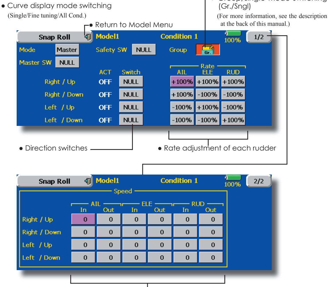
- Adjustment of the servo speed of each rudder
(For a description of the setting method, see the description at the back of this manual.)
Multi Engine
[Corresponding model type]: Airplane, general
This function lets you adjust the throttle when using a multi engine airplane with up to 4 engines. The Throttle Cut function, Idle Down function, Throttle Hold function, High Trim, and Idle Trim can be adjusted by throttle channel (THR, THR2, THR3, THR4).
*Initial setting assigns only one throttle channel (THR). When using this function, the number of throttle channels must be assigned beforehand at the Function menu of the Linkage Menu.
- The throttle cut position can be set for each throttle channel. Throttle cut operation is linked to the switch set with the Throttle Cut function of the Linkage Menu.
*The throttle cut position set at this screen is effective.
- The throttle down offset rate can be set for each throttle channel. Idle down operation is linked to the switch set with the Idle Down function of the Linkage Menu.
*The idle down offset rate set at this screen is effective. - Operation can be fixed at the engine speed (carburetor opening angle) for each throttle channel with the Hold Position function. The hold position can be changed.
-
High side trim and idle trim can be set for each channel. Operation acts as high trim or idle trim based on the center.
-
Touch the [Multi Engine] button in the Model Menu to call the setup screen shown below.
*The number of engines (1~4) assigned by Function menu in the Linkage Menu setup screen is displayed.
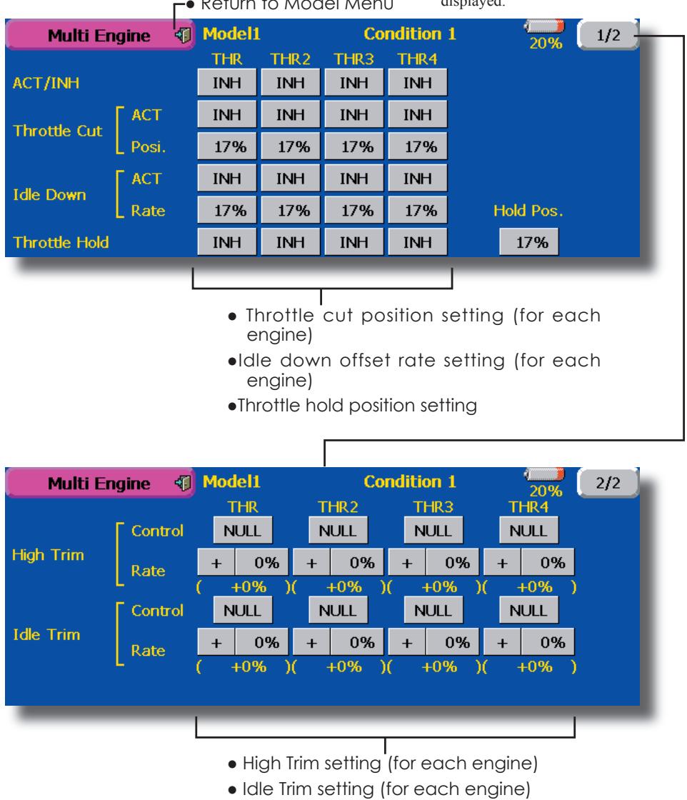
MODEL MENU (HELICOPTER)
This section contains information on the commands that apply to helicopters only. For instructions on Airplanes and Sailplanes, refer to the sections pertaining to those aircraft. Each of these functions can be set independently for different flight conditions. To get to these settings, touch the desired function button to be entered.
Use the Model Type function in the Linkage Menu to select the swash type matched to the
fuselage beforehand. If you later change model types, all settings will be lost.
Also, add flight conditions at the Condition Select screen before setting the model data at each function. (Up to 8 conditions can be used)
The AFR function, fuel mixture and other functions common to all model types, are described in a separate section.
- Touch the Model Menu button of the Home screen to call the menu shown below. Touch the button of the function you want to set to call the setup screen.
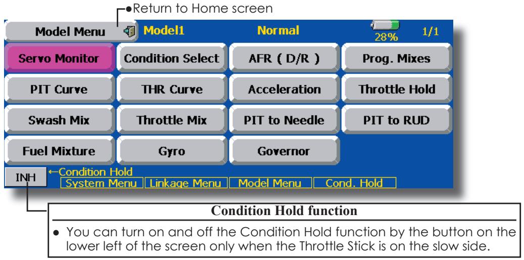
Model Menu functions (helicopter) list
PIT Curve: Adjusts response in different flight conditions
THR Curve: Throttle curve and hovering trim adjustment
Acceleration: Counteracts torque due to sudden throttle and pitch commands
Throttle Hold: Moves the throttle to idle during autorotation
Swash Mix: Compensates for each control response
Throttle Mix: Compensates for power loss when cyclic applied
Pit to Needle: Adjusts response curve in different flight conditions
Pit to RUD: Handles torque changes from pitch angle inputs
Fuel Mixture: Commands a second servo to adjust the fuel mixture at the carburetor
Gyro: Used to switch gyro sensitivity
Governor: Used to switch RPM of the helicopter's head
PIT Curve
This function adjusts the pitch operation curve for each flight condition for the optimal flight state relative to movement of the throttle stick.
The pitch curve can be freely selected from linear operation curve to smooth curve, and adjusted to match the curve you want by means of the T14MZ's powerful Curve Edit Function (6 types of curves can be selected). Up to 17 points can be set for linear or curve types. However, when using
the 3 points or 5 points specified to create a curve, a simple and smooth curve can be created by selecting the curve type and reducing the number of input points to 3 or 5, and then entering the specified value at the corresponding points that you created.a curve, a simple and smooth curve can be created by selecting the curve type and reducing the number of input points to 3 or 5, and then entering the specified value at the corresponding points that you created.
- Touch the [PIT Curve] button in the Model Menu to call the setup screen shown below.
- There are 4 types of display. The curve of all the conditions or the pitch and throttle curves can be displayed on one screen.
Linear type is 9 points, but for simple use, 4 5 points are sufficient.
Normally use Separate.
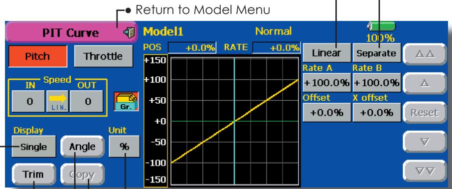
- Trim can be used as hovering pitch and pitch trim. The high and low side pitch can be fine-tuned.
Units can be selected from [%] and [Deg]. When [Deg] is selected, the rotor pitch angle is displayed and becomes the setting standard. When [Deg] was selected, the high, center, and low pitch angles are entered.
Can be copied to the pitch trim adjustment position.
When the [Angle] button is touched, the pitch angle input screen is displayed. Input the maximum pitch, center, and low pitch.
Normal curve adjustment
- For normal curve, usually use [Line] type and create a basic pitch curve centered about hovering. Use this function together with the THR Curve (Normal) function and adjust the curve so that up/down control is best at a constant engine speed.
Idle up curve adjustment
- For the high side pitch curve, set the maximum pitch which does not apply a load to the engine. For the low side pitch curve, create curves matched to loop, roll, 3D, and other purposes and use the idle up curves according to the performance.
Note: When the curve type is changed, the data is reset.
Throttle hold curve adjustment
- The throttle hold curve is used when executing auto rotation dives.
Operation precautions
WARNING
When actually starting the engine and flying, always set the idle up condition switch to [OFF] and start the engine in the idling state.
Setting method
- Group button: When you also want to input the same setting contents at other conditions, perform setting in the group mode (initial setting). In this case, the same contents are input to the other conditions set in the group mode. When you want to set each condition independently, select the single mode. Other conditions can be set independently.
- Normal % input or angle input can be selected at rate adjustment at curve setting. For angle input, if the high side, low side, and center angles are input beforehand, the rate can be set by reading the angle directly (standard).
- The curve graph display mode can be selected. This is convenient when checking curves other than the curve currently being set. [Sngl]: Displays only the curve currently being set
[Fine Tuning]: When pitch trim is used, a curve with pitch trim adjustment added is also displayed. [All Cond.]: Displays the pitch curve of all the conditions. The curve of the condition currently in use is indicated by a bold line. PIT&THR: The throttle hold curve of the condition currently in use is also displayed.
- The Throttle Curve setup screen can be called with one touch, which is convenient when making adjustments alternately with the throttle curve.
- The servo operation speed can be set. When adjusted when the pitch is too sensitive, the pitch operation feeling can be changed.
- When increasing the number of points, use the cursor keys [<] [>] to move the cursor to the point where you want to enter a point (■) and touch the Rate button. The point is created.
Curve setting examples
The screens shown below are curves created by entering the pitch angle at low, center, and high side 3 points or 5 points at each condition. They were created by reducing the number of points to the 3 points of low side, center, and high side. When actually creating a curve, input the angle specified
at the fuselage (or the reference value).
*For a description of the curve setting method, see the description at the back of this manual.
- Pitch Curve (Example)
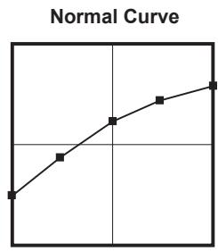
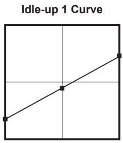
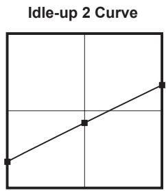
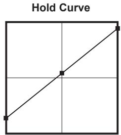
Pitch Trim (Hovering pitch, high pitch, low pitch)
The hovering pitch, low pitch, and high pitch trim setup screen can be called from the PIT Curve setup screen.

Hovering pitch trim
The Hovering Pitch function trims the pitch near the hovering point. Normally, it is used with the hovering condition. The hovering pitch can be fine tuned for changes in rotor speed accompanying changes in temperature, humidity, and other flight conditions. Adjust the hovering pitch so that rotor speed is constant. This function can be used together with the Hovering Throttle Trim function for more delicate operation.
Setting method
- When using only the hovering (normal) condition, switch the group button to the single mode before setting.
- Set the function to ACT [ON].
- Select the adjustment knob. Selection example: LD or T6
- The trim operation mode (Mode: CTRM/NORM) can be selected.
CTRM mode: Maximum amount of change near center by center trim operation
NORM mode: Normal trim (parallel movement trim) operation. The advantage of using this mode is that the hovering pitch can be adjusted without changing the curve.
- Trim adjustment range (Range) setting
When this value is made small, trim can only be used near the center. - The trim rate can be adjusted and the operation direction can be changed.
High Pitch/Low Pitch Trim
High Pitch/Low Pitch Trim is the pitch servo high side and low side trim function.
Setting method
- When setting the adjustment knobs common to all the conditions, set them in the group mode.
- Set the function to ACT (ON).
- Select the adjustment knobs. Selection example: LST (high side), RST (low side)
- The trim rate can be adjusted and the operation direction can be changed.
- Trim acts as high side or low side trim with the center as the standard.
THR Curve
This function adjusts the throttle operation curve for each condition for optimum the engine speed to throttle stick movement.
A throttle curve from linear operation curve to smooth curve can be set. Adjustment to the curve you want to use is possible by using the 14MZ's powerful Curve Edit Function. Up to 17 curve
points can be set, however, when the 5 points and other point data is used, a smooth curve can be easily created by reducing the number of input points of the curve to 5 and entering the specified value at the corresponding points.
- Touch the [THR Curve] button in the Model Menu to call the setup screen shown below.
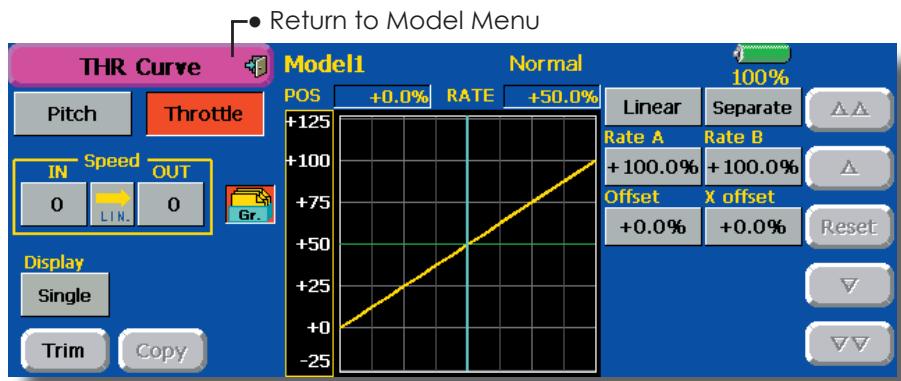
Normal curve adjustment
- Normal curve creates a basic curve centered around hovering. Use it along with the normal pitch curve and adjust so that up/down control at a constant engine speed is easiest.
Idle up curve adjustment
- Set a normal up curve that maintains a constant speed at all times, even when operation which reduces the pitch was performed in flight. Create a curve matched to loop, roll, 3D, or other purposes and the idle up curve according to the performance.
Setting method
- Group button: When you want to simultaneously enter the same settings to other functions, make the settings in the group mode. (Initial setting) In this case, the same setting contents are entered to the other conditions in the group mode. When you want to set each condition independently, make the settings after selecting the single mode.
- The curve graph display mode can be selected. This is convenient when checking curves other than the one being set. [Sngl]: Displays only the curve being set. [Fine Tuning]: When Throttle Hover trim is used, a curve with trim adjustment added is also
Operation precautions
WARNING
When actually starting the engine and flying, always set the idle up condition switch to [OFF] and start the engine in the idling mode.
displayed.
[All Cond.]: Displays the throttle curve of all the conditions. The curve of the condition currently in use is indicated by a bold line.
[PIT&THR]: The pitch curve of the condition currently in use is also displayed.
- The pitch curve setup screen can be called with one touch. This is convenient when alternately adjusting these curves with the pitch curve.
- The servo speed can be set. Adjust the throttle speed when the throttle is too sensitive
Curve setting examples
The curves shown below were created by using the Line mode and inputting the data of the 5 points 0% (low side), 25% , 50% (center), 75% , 100% (high) side at each condition. They were created by reducing the number points of the line to 5. When
actually creating a curve, enter the data specified per the fuselage (or the reference value).
*For a description of the curve creation method, see the description at the back of this manual.
- Throttle Curve (Example)
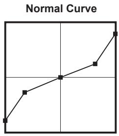
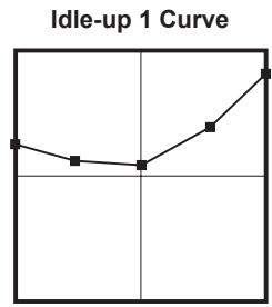
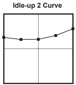
Throttle Hover trim
The Throttle Hover trim setup screen can be called from the THR Curve setup screen.
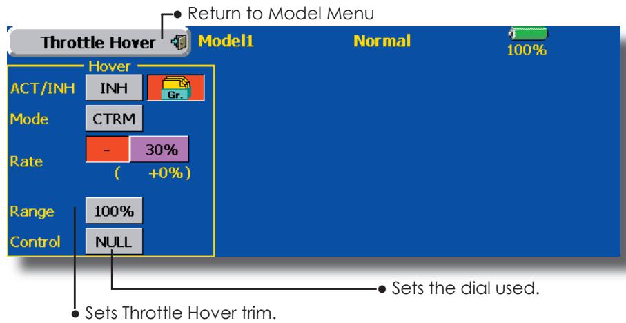
The Throttle Hover function trims the throttle near the hovering point. Normally, use it with hovering conditions. Changes in rotor speed accompanying changes in the temperature, humidity, and other flight conditions can be trimmed. Adjust the throttle so that rotor rotation is most stable. More delicate trimming is also possible by using this function along with the Hover Pitch function.
Setting method
- When using the hovering (normal) condition only, switch the Gr. mode to the Sngl mode and make the settings.
- Set the function to ACT ([ON]).
- Select the adjustment knob. Selection example: RD
- The trim operation mode (Mode: CTRM/NORM)
can be selected.
CTRM mode: Maximum rate of change near center by center trim operation
NORM mode: Normal trim (horizontal movement trim) operation. The advantage of using this mode is that hovering throttle can be adjusted without changing the curve.
- Trim adjustment range (Range) setting When the value is made small, trim acts only near the center.
- The trim rate can be adjusted and the operation direction can be set.
Acceleration Mixing
This function is used to adjust the pitch and the throttle rise characteristic at acceleration/ deceleration operation. An acceleration function which temporarily increases the pitch and throttle operations at throttle stick acceleration/deceleration operation can be set.
Example of acceleration function use
- When used at pitch, the Acceleration function is effective when you want to quicken the response of the fuselage at 3D flight flip, etc.
When used, high pitch temporarily exceeds maximum pitch, but immediately returns to maximum pitch.
Using Acceleration with Pitch is effective when you want to maximize speed for 3D aerobatics and other aircraft responses. As an example, "High pitch" temporarily overrides "maximum pitch" and immediately returns to the maximum pitch position.
- Touch the [Acceleration] button in the Model Menu to call the setup screen shown below.
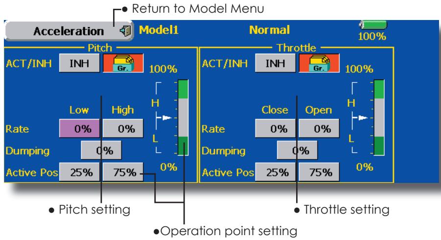
Setting method
- Acceleration can be set at both setting at acceleration (high) and setting at deceleration (low). (The operation point is displayed on a graph.)
- Acceleration rate setting (Rate)
- The return time after operation (Dumping) can be set.
- The operation point at acceleration and deceleration can be set. When an operation point is exceeded, acceleration is performed.
Note: When using the Acceleration funtion, since the pitch stroke is large, make your settings so there is no binding of your linkage.
Throttle Hold
This function sets the throttle cut position at auto rotation dive. The throttle position can also be set to an idling position separate from the throttle cut position. Setting of these 2 positions can be selected by switch. This allows use for switching during training.
Example of use
- Since Throttle Hold has 2 modes (Cut) and (Idle), using it in the Idling mode during training and in the Cut mode when stopping the engine at meets, etc. is convenient.
Note: When throttle hold is set to ON in the normal condition, throttle hold acts and the throttle servo is deactivated. Always set throttle hold to ON in the hold condition.
- Touch the [Throttle Hold] button in the Model Menu to call the setup screen shown below.
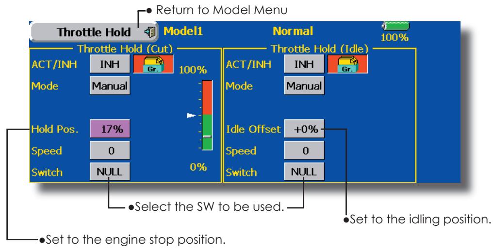
Setting method
Operation mode selection
Manual mode: The throttle hold function is operated by switch operation only.
Auto mode: The throttle hold function operation is linked to the throttle stick position.
Auto position setting: When the Auto mode was selected, the throttle position (auto position) can be selected. Move the throttle stick to the position you want to set and touch the (auto position) button.
- Hold position adjustment
Throttle Hold (Cut) sets the throttle cut position. Adjust it so that the carburetor is full open.
Throttle Hold (Idle): Make this adjustment to maintain idling for training. Adjustments can be made based on the throttle curve idle position.
- The throttle servo operating speed can be adjusted. (Speed)
- Throttle cut or training function can be switched by hold function selector switch.
Operation precautions
WARNING
When starting the engine, confirm that the idle up condition and throttle hold condition are [OFF].
Swash mixing
The swash mix function is used to correct the swash plate in the aileron (roll) direction and elevator (cyclic pitch) corresponding to each operation of each condition.
Adjustment by independent curve for aileron, elevator, and pitch operations is possible. The operation can be smoothly adjusted by calling up the "Curve setup" screen by touching the button that corresponds to the mixing and direction which needs correction.
Example of use
- As an example, use swash mixing to correct undesirable tendencies in the roll direction
-
For a condition which uses AIL to ELE, set this function to ON. When raising the nose at a right roll, when the Rate B side is input and the right aileron is operated, the elevator moves to the down side. Tune by adjusting the Rate. For right roll, adjust to the Rate A side.
-
Touch the [Swash Mix] button in the Model Menu to call the setup screen shown below.
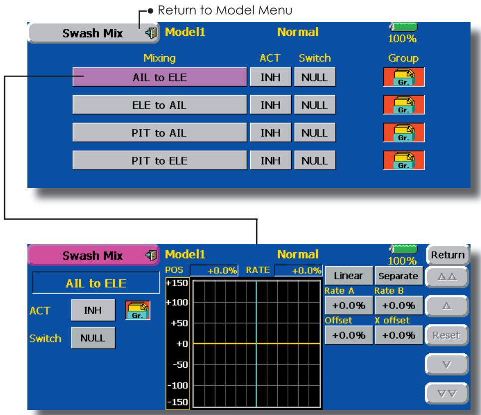
Setting method
- When using this function, touch the [INH] button and display [ON] or [OFF].
- When you want to set the same contents at other conditions, select the group mode (Gr.). When you want to set the selected condition only, select the single mode (Sngl).
- The correction rate can be set by curve.
- A switch can be set. When [NULL] is set, the swash mixing function is operated by merely selecting the condition.
When setting an [ON]/[OFF] switch, touch the [NULL] button and set the switch and its ON position at the
Throttle mixing
This function corrects slowing of engine speed caused by swash plate operation at aileron or elevator operation. The method of applying clockwise or counterclockwise torque when pirouetting can also be corrected.
An acceleration function which temporarily increases the throttle side correction rate relative to rapid stick operation can also be set.
When correction is necessary, touch the mixing corresponding to the mixing that needs correction to call the curve setup screen, and then correct the slowing.
Setting example
-
All to THR applies a load to the engine and corrects sinking of the engine speed when the throttle stick was operated. Engine racing can be adjusted independently at the right aileron and left aileron by Rates A and B.
-
Touch the [Throttle Mix] button in the Model Menu to call the setup screen shown below.
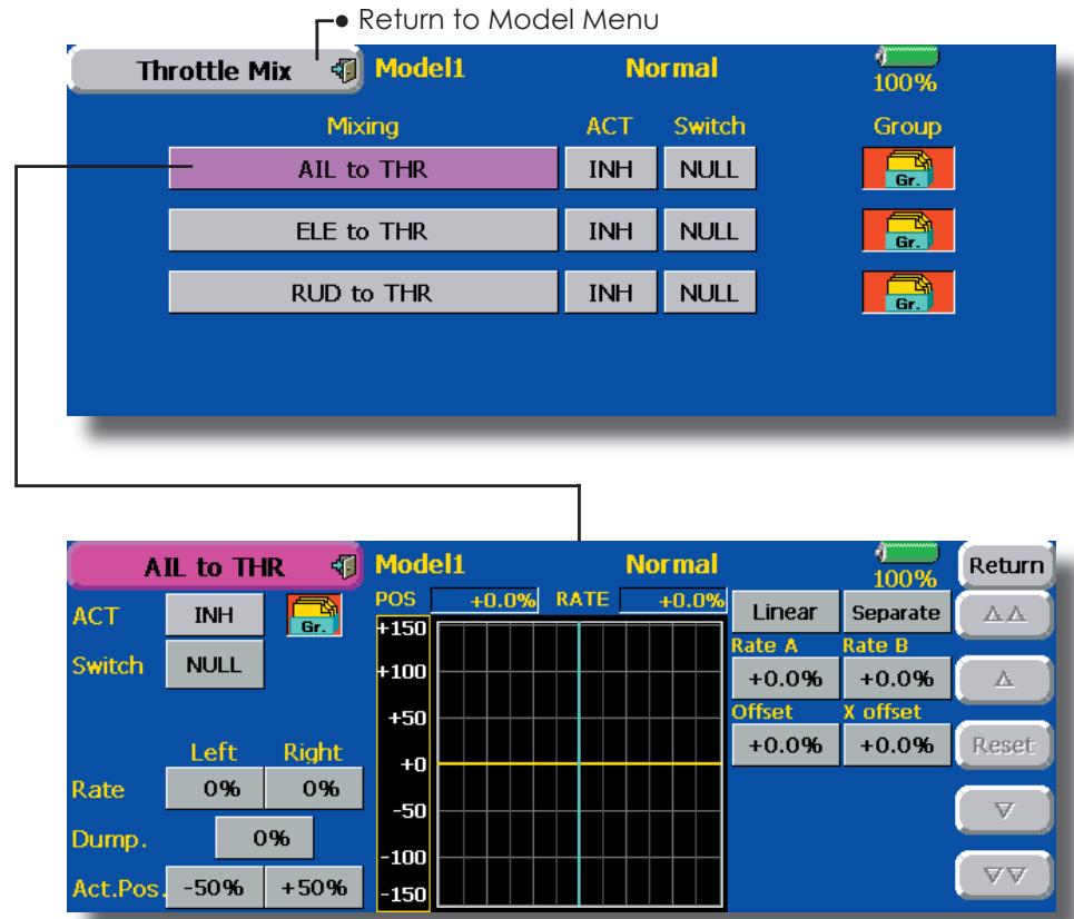
Setting method
- When using this function, touch the [INH] button and display [ON] or [OFF].
- When you want to set the same contents at other conditions, select the group model (Gr.). When you want to set the selected condition only, select the single mode (Sngl).
- The correction rate can be set by curve.
- A switch can be set.
When [NULL] is set, the function is operated by merely selecting the condition.
When setting an [ON]/[OFF] switch, touch the [NULL] button and then set the switch and its ON direction at thescreen.
- Acceleration can be set for both settings (High) and (Low) at maximum correction rate.
- Acceleration rate setting (Rate)
- The return time (Dump.) after operation can be set.
- The operation point when the correction rate is increased and decreased can be set independently. When an operation point is exceeded, acceleration operation is performed.
PIT to Needle mixing
This mixing is used when the engine is equipped with needle control or other fuel-air mixture adjustment. A needle curve can be set.
An acceleration function which temporarily increases needle operation at throttle stick acceleration/deceleration operation can be set. The rise characteristic of the needle servo at acceleration and deceleration operation can be adjusted.
- Touch the [PIT to Needle] button in the Model Menu to call the setup screen shown below.
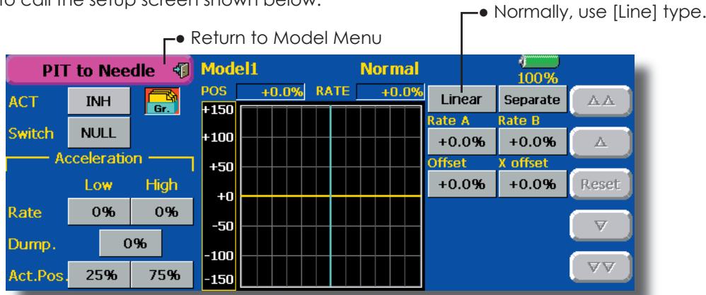
Setting method
- When using this function, touch the [INH] button and display [ON] or [OFF].
- When you want to set the same contents at other conditions, select the group mode (Gr.). When you want to set the selected condition only, select the single mode (Sngl).
- A needle curve can be set.
A switch can be set.
When [NULL] is set, the function is operated by merely selecting the condition. When setting and [ON]/[OFF] switch, touch the [NULL] button and set the switch and its ON direction at the
- Acceleration can be set at both setting at acceleration (High) and setting at deceleration (Low).
- The acceleration rate (Rate) and the return time after operation (Dump.) can be set.
- An operation point (Operation Point) at acceleration and deceleration can be set. When an operation point was exceeded, acceleration operation is performed.
PIT to RUD mixing (Revolution mixing)
Use this mixing when you want to suppress the reaction torque generated by main rotor pitch and speed changes at pitch operation. Adjust so that the nose does not move in the rudder direction.
An acceleration function which temporarily increases the correction rate at throttle stick acceleration/deceleration operation can be set. The mixing rate at acceleration/deceleration can be set.
However, when a GY Series or other heading hold gyro is used, since correction is performed by the gyro, this mixing is not used. If this function is used when the gyro operation mode is the AVCS mode, the neutral position will change.
- Touch the [PIT to RUD] button in the Model Menu to call the setup screen shown below.
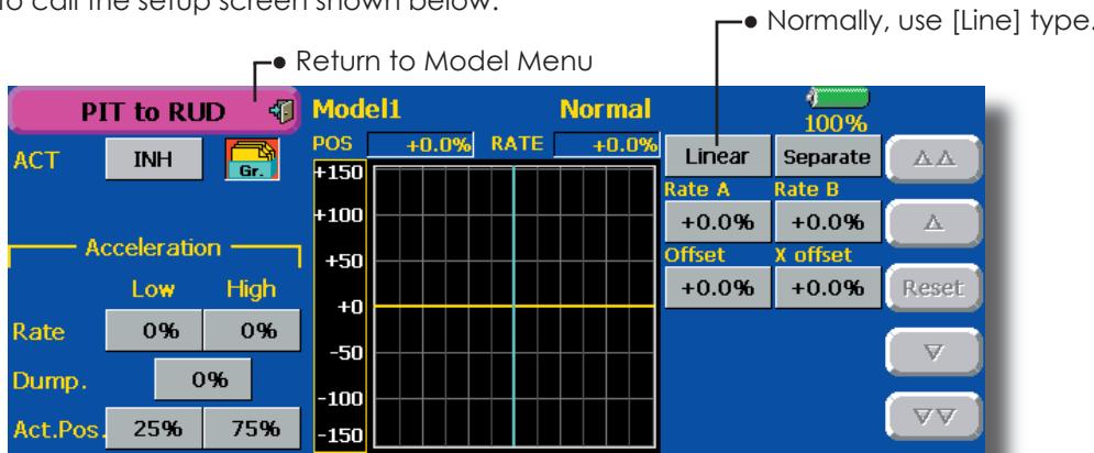
Setting method
- When using this function, touch the [INH] button and display [ON] or [OFF].
- When you want to set the same contents at other conditions, select the group mode (Gr.). When you want to set the selected condition only, select the single mode (Sngl).
- A mixing curve is set.
The mixing curve rate starts from a small value.
For a rotor with a clockwise operation direction (polarity), when pitch was operated at the plus side, set so that mixing is in the clockwise direction. First, trim at hovering and then adjust the neutral position.
- Adjustment between slow and hovering
Repeatedly hover from take off and land from hovering at a constant rate matched to your own rhythm, and adjust the pitch so the nose does not deflect when the throttle is raised and lowered.
- Throttle high side (up to climbing from hovering and diving hovering)
*Repeat climbing and diving from hovering at a constant rate matched to your own rhythm and adjust the pitch so that the nose does not deflect when the throttle is raised and lowered.
Set the mixing rate so that the rudder direction at high-speed flight is straight ahead. Adjust for each condition used.
- Acceleration operation can be performed for both setting at acceleration (High) and setting at deceleration (Low).
- Acceleration rate setting (Rate)
- The return time after operation (Dump.) can be set.
- An operation point (Operation Point) at acceleration and deceleration can be set independently. When an operation point was exceeded, acceleration operation is performed.
Gyro mixing
This function used to adjust gyro sensitivity. The sensitivity and operation mode (Normal mode/GY mode) can be set for each condition.
*Sensitivity setting is assigned to CH3.
Note: Always set both (ACT) and (Trim) for the [Gyro] function.
Setting example
-
Normally, it is convenient to preset high sensitivity (Rate 1) and low sensitivity (Rate 2) when either the AVCS mode or Normal mode is used.
-
Touch the [Gyro] button in the Model Menu to call the setup screen shown below.
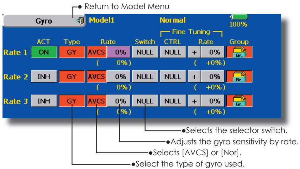
Setting method
- Touch the [INH] button of the rate to be used and display [ON].
- When you want to set the same contents at other conditions, select the group mode (Gr.). When you want to set the selected condition only, select the single mode (Sngl).
- Three rates can be switched for each condition. (Rate 1/Rate 2/Rate 3)
- A fine tuning VR can be set.
Governor mixing
This is used to switch the RPM of the helicopters head. Up to 3 rates can be set for each condition.
The governor is used by connecting the governor speed setting channel to CH7 (initial setting).
When using an independent governor [ON]/[OFF] switch, connect the AUX([ON]/[OFF]) connector of the governor to CH8 (initial setting) and set the switch to CH2 (Governor2) at the Function menu of the Linkage Menu.
*When using the Fuel Mixture function, the mixture servo is controlled from the governor. When transmitting the mixture curve data from the transmitter to the governor, the governor AUX (m.trm) connector must be connected to CH8 (initial setting) and governor side setting performed. See the governor instruction manual.
Note: Always set (Act) and (Trim) to [NULL] for [Governor] and [Governor 2] of the Function menu.
- Touch the [Governor] button of the Model Menu to call the setup screen shown below.
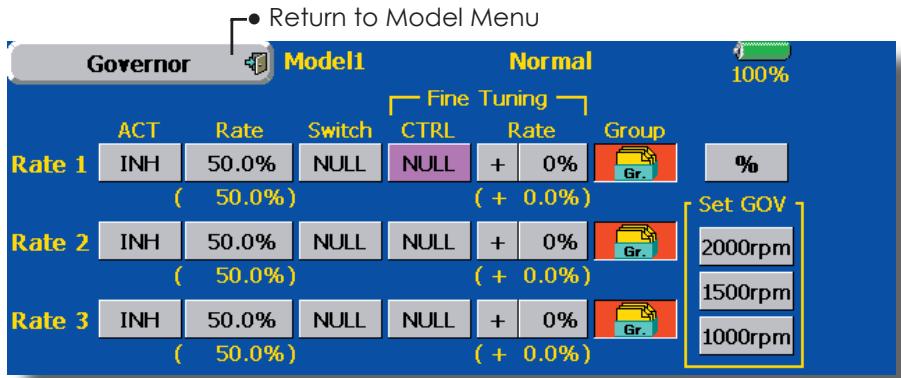
Setting method
- Touch the [INH] button of the rate to be used and display [ON].
- When you want to set the same contents at other functions, select the group mode (Gr.). When you want to set the selected condition only, select the single mode (Sngl).
- Three speeds (rates) can be set for each condition. (Rate 1/Rate 2/Rate 3)
Also, this mixing and the governor side speed setting must be matched beforehand by the following method:
-
Set so that when the governor side is placed in the speed setting item state and [2000rpm] of Set GOV of the screen above is touched, the governor speed is set to "2000", when the [1500rpm] button is touched, the governor speed is set to "1500", and when the [1000rpm] button is touched, the governor speed is set to "1000".
-
When you want to read the speed directly, press the [%] button and display [rpm].
- The speed can be witched by setting a switch. Also, when [OFF] is set instead of speed setting, the governor can be turned [ON]/[OFF] without setting a separate [ON]/[OFF] switch.
- A speed fine tuning VR can be set.
*VR selection, adjustment width, and adjustment direction can be set.
Common operations used in function setup screen
This section describes the functions often used at the function setup screen. Refer to it when setting each function.
Operations related to flight conditions
Group/single mode switching (Gr./Sngl)

When setting multiple flight conditions, linking the setting contents with other conditions (Gr.) or setting independently (Sngl) can be selected. When the button is touched, it toggles between Gr. and Sngl.
Group mode (Gr.) (initial setting): The same setting contents are set to all the flight conditions in the group mode.
Single mode (Sngl): Select this mode when the setting contents are not linked with other conditions.
*Selecting the single (Sngl) mode at each condition after presetting in the group mode (Gr.) is convenient.
Condition delay setting
Unnecessary fuselage motion generated when there are sudden changes in the servo position and variations in the operating time between channels at condition switching can be suppressed.
When the delay function is set at the switching destination condition, a delay corresponding to that amount is applied and the related functions change smoothly.
[Setting method]
- Switch to the condition you want to set.
- Touch the Delay button.
- Use the adjustment buttons to set the delay.
Initial value: 0
Adjustment range: 0~25 (maximum delay)
Operations related to VR tuning
Fine tuning VR setting
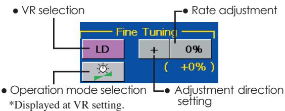
[Operation modes]

Mixing rate 0% at center of VR When the VR is turned counterclockwise and clockwise, the mixing rate increases and decreases, respectively.

Mixing rate 0% at left end of VR When the VR is turned, the mixing rate increases.

Mixing rate 0% at right end of VR. When the VR is turned, the mixing rate increases.

When the VR is turned to the left or right of the neutral position, the mixing rate increases.
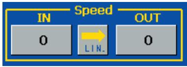
Servo speed setting (1)
The speed at each operation (including flight condition switching) can be adjusted. The servos operate smoothly at a constant speed corresponding to the set speed. The operation speed (In Speed) and the return speed (Out Speed) can be set individually.
Switch the operation mode according to the set function. When the button is touched, it toggles between [LIN] and [SYM].
"SYM" mode: Mode used with ailerons and other self-neutral functions
"LIN" mode: Mode used with functions which hold the operation position of the throttle and switch channel, etc.
[Setting method]
- Select the function ([LIN] or [SYM]) matched to the master channel. Each time the button is touched, it toggles between [LIN] and [SYM].
- Touch the In or Out Speed button and set the servo speed.
Initial value: 0
Setting range: 0~25
![FUTABA 14MZ - [Setting method] - 1](/content/2025/01/163546/images/e02cd69520bed94f395cf510a7c27986005bdb035f3237b2a9ee0c0cff9316a6.jpg)
![FUTABA 14MZ - [Setting method] - 2](/content/2025/01/163546/images/202a171871a1b27456b8f5bfbb097fb19fc7c6d4ea2ceb11a7f07070d3b6d8f2.jpg)
Servo speed setting (2)
[Setting method]
- When setting the servo speed, touch the Speed button. The Servo Speed setup screen shown above is displayed.
- Select the function ([LIN] or [SYM]) matched to the master channel. Each time the button is touched, it toggles between [LIN] and [SYM].
"SYM" mode: Mode used with ailerons and other self-neutral functions.
"LIN" mode: Mode used with functions which hold the operating position of the throttle and switch channel, etc. - Touch the In Speed button and set the servo speed.
Initial value: 0
Setting range: 0~25
- Touch the Out Speed button and set the servo speed.
Initial setting: 0
Setting range: 0~25
- Touch the Start Delay button and set the delay time from switch ON to the start of function operation.
Initial setting: 0.0 sec
Setting range: 0~4 secs
- Touch the Stop Delay button and set the delay time from switch OFF to the start of function operation.
Initial setting: 0
Setting range: 0~4 secs
Curve setting operation
This section describes the setting procedure of curves which are used with the AFR function and each mixing function.
Curve type selection
When the curve type select button on the mixing function screen or other screen is touched, the setup screen shown below is called.
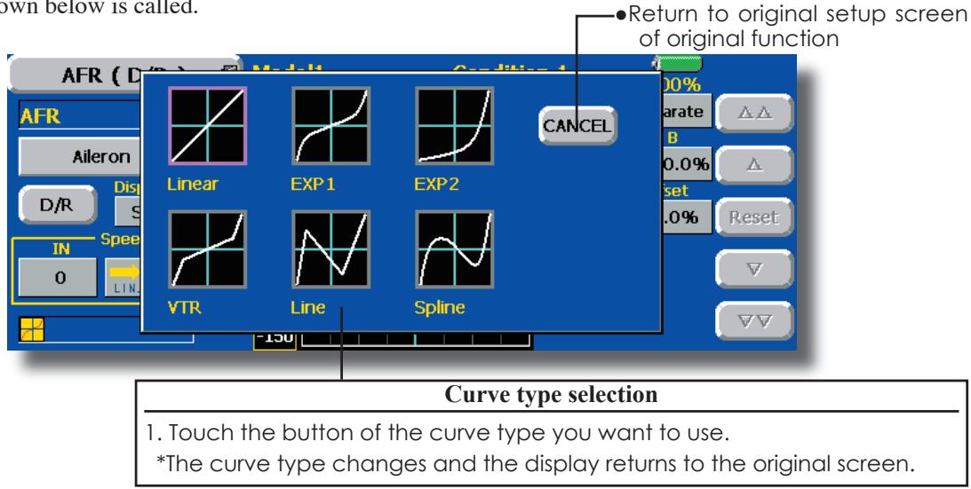
Setting by curve type
When the curve type is selected as described above, adjustment buttons corresponding to the curve type appear on the original screen. Adjust each curve as described below.
Linear curve adjustment
Rate A and Rate B can be adjusted separately or simultaneously.
[Setting modes]
-
[Separate] mode: Rates are adjusted separately.
-
[Combined] mode: Rates are adjusted simultaneously.
[Setting method]
- Select the setting mode.
- Touch the Rate A or Rate B button.
- Use the adjustment buttons to set the rate.
*Initial value: +100.0%
*Adjustment range: -200.0~+200.0%
The curve can also be offset horizontally in the vertical direction and the rate reference point can be offset to the left or right.
[Offsetting the curve horizontally in the vertical direction]
- Touch the Offset button.
- Use the adjustment buttons to move the curve horizontally up and down.
*Initial value: +0.0%
[Offsetting the rate reference point to the left or right]
- Touch the X Offset button.
- Use the adjustment buttons to move the reference point to the left or right.
*Initial value: +0.0%
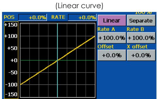
EXP1 curve adjustment
Rate A and Rate B can be adjusted separately or simultaneously. The EXP curves rate (EXP A, EXP B) can also be adjusted separately or simultaneously.
[Setting modes]
-
[Separate] mode: Rates are adjusted separately.
-
[Combined] mode: Rates are adjusted simultaneously.
[Setting method]
- Select the setting mode.
- Touch the button of the rate or EXP curve rate your want to set.
- Use the adjustment buttons to set the rate.
*Initial value: +100.0% (rate), +0.0 (EXP rate)
The curve can also be horizontally offset in the vertical direction.
[Offsetting the curve horizontally in the vertical direction]
- Touch the Offset button.
- Use the adjustment buttons to move the curve horizontally up or down.
*Initial value: +0.0
VTR curve adjustment
Rate A and Rate B can be adjusted separately or simultaneously. The VTR curve point positions (P. Pos. A, P. Pos. B) and rates (P. Rate A, P. Rate B) can also be adjusted separately or simultaneously.
[Setting modes]
- [Separate] mode: Positions and rates are adjusted separately.
*[Combined] mode: Positions and rates are adjusted simultaneously.
[Setting method]
- Select the setting mode.
- Touch the button of the rate or VTR curve point position (or rate) you want to set.
- Use the adjustment buttons to set the VTR curve point position (or rate).
*Initial values: +100.0% (Rate), -50.0% (P(Pos.A), +50.0% (P(Pos.B), +0.0% (P. Rate)
The curve can also be offset horizontally in the vertical direction.
[Offsetting the curve horizontally in the vertical direction]
- Touch the Offset button.
- Use the adjustment buttons to move the curve horizontally up and down with the adjustment buttons.
*Initial value: +0.0%
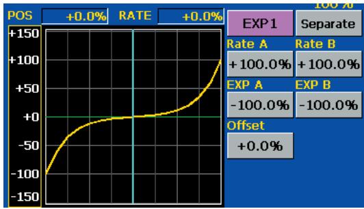
(EXP1 curve)
- Using the EXP1 curve is helpful in smoothening starting of the ailerons, elevators, rudder, etc.
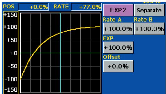
(EXP2 curve)
- Using the EXP2 curve is helpful in engine rise and other engine control.
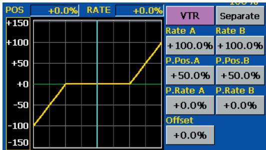
(VTR curve)
- Setting is fast if left, right, up, and down are first decided in the Combined mode and the mode is then switched to the Separate mode.
When this curve is used when the operating rudder angle is large such as with acrobatic models, switching from normal flight to acrobatic rudder angle is performed without switch operation.
Line and spline curve adjustment
Line curves or spline curves of up to 17 points can be used. (Initial value: 9 points) The set points can be freely increased, decreased, and offset. Curves which are symmetrical to the left and right of center can also be set.
[Setting modes]
- [Separate] mode: Normal setting
*[Combined] mode: Creates a left and right symmetrical curve.
[Adjusting the rate of each point]
- Use the move between points buttons [ << ] or [ >> ] to select the point. (The pink point is the selected point.)
- Touch the Rate button.
- Use the adjustment buttons to adjust the rate.
[Point addition method]
- After touching the point button, move the stick, etc. to the point you want to add and press the [Move] button. (An outlined point appears on the graph.)
Or move the stick, etc. to the position you want to add and press the [Move] button. (An outlined point appears on the graph.) - Use the move buttons [< ] or [>] to fine adjust the position.
- Touch the Rate button.
*A new point is created.
[Point deletion]
- Use the move between points button [ << ] or [ >> ] and select the point. (The pink point is the selected point.)
- Touch the [Delete] button. (The selected point becomes an outlined point.)
- Touch the move between point button [<<] or [>>] .
*The point is deleted.
The curve can also be offset horizontally in the vertical direction.
[Offsetting the curve horizontally in the vertical direction]
- Touch the Offset button.
- Use the adjustment buttons to move the curve horizontally up and down.
*Initial value: +0.0%
![FUTABA 14MZ - [Point deletion] - 1](/content/2025/01/163546/images/0c1a61cc0e98cb39d48c88b7e51bbe6367b69a22006993c01435401580b77445.jpg)
(Line curve)
![FUTABA 14MZ - [Point deletion] - 2](/content/2025/01/163546/images/73cc57763a30fea0aff8f122cd0806ec0ad5a15740e37563afb5c1c81cd171d8.jpg)
(Spline curve)
![FUTABA 14MZ - [Point deletion] - 3](/content/2025/01/163546/images/002df9de3b1ec3c2812894cf9f2076bd73d1ec0ca7464feefa3c6b4e7db1e88f.jpg)
(Rate adjustment buttons)
Switch selection method
The various functions used in the T14MZ can be selected by switch. The switch (including when stick, trim lever, or VR are used as a switch) setting method is common to all functions.
Switch selection
When the switch select button at a mixing function screen or other screen is touched, the selection shown below is called.
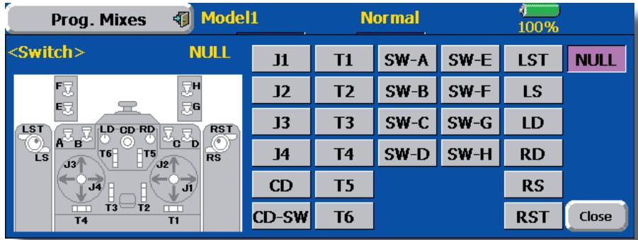
(Switch selection screen example)
When switch is selected
Switch ON/OFF setting is possible at each position.
When stick, trim lever, or VR is selected.
When a stick, trim lever, or VR is used as a switch, the following 4 modes can be selected.
Mode: Lin/Sym
-Type: Hysteresis (Hys.)/box (Box)
- When the ON position switch is touched after the switch was selected, the screen shown below appears.
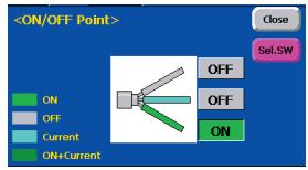
*When the button of each position is touched, it toggles between ON and OFF.
- Touch the button and set to the ON position.
-
Close the screen by touching [Close].
-
When the ON position button is touched after stick, etc. was selected, the screen shown below appears.

- Select the mode you want to use, and set it as described below.
- Close the screen by touching [Close].
Operation modes
The operation modes when stick, trim lever or VR are selected are described below. Change the operation mode by touching the Mode and Type buttons.
Linear hysteresis mode
This setting method selects function ON/OFF based on the set point. Hysteresis (dead band) can be set between ON and OFF. The ON and OFF positions can be reversed with the Reverse button.
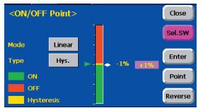
Symmetrical hysteresis mode
Operation is the same as the linear hysteresis mode, but left and right (up and down) operations are symmetrical about the neutral position. For example, when you want to switch DR1 with the aileron stick, when the stick is moved to the left or right, DR1 can be turned ON at the same left and right position.
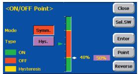
When shifting the ON/OFF point
The ON/OFF and hysteresis (dead band) boundary point (there are 2 points: top and bottom) position can be shifted. ON/OFF is possible at a free position.
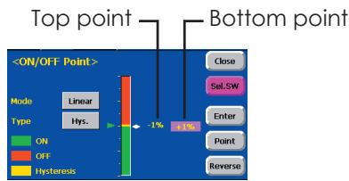
[Setting method]
- Select the top and bottom boundary points with the [Point] button.
- Move the stick, etc. to the point you want to shift and touch the [Enter] button. The boundary points change.
*Also shift other points, as required.
Linear box mode
This mode turns on the switch within a range of 2 points. Each point can be set. The ON and OFF positions can be reversed with the Reverse switch.
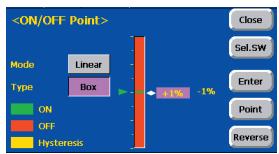
Symmetrical box mode
Operation is the same as the linear box mode, but left and right (up and down) operation is symmetrical about the neutral position.