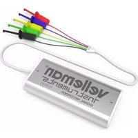
PCRU01 - Measuring equipment VELLEMAN - Free user manual and instructions
Find the device manual for free PCRU01 VELLEMAN in PDF.


| Product Type | Digital Multimeter |
| Brand | Velleman |
| Model | PCRU01 |
| Category | Measuring Equipment |
| Dimensions | Approx. 150 x 70 x 30 mm |
| Weight | Approx. 200 g (including battery) |
| Power Supply | 9V battery (6F22 or equivalent) |
| Display | LCD, max reading 1999 |
| DC Voltage Measurement | 200 mV, 2 V, 20 V, 200 V, 600 V |
| AC Voltage Measurement | 200 V, 600 V |
| DC Current Measurement | 200 µA, 2 mA, 20 mA, 200 mA, 10 A |
| Resistance Measurement | 200 Ω, 2 kΩ, 20 kΩ, 200 kΩ, 2 MΩ |
| Additional Functions | Diode test, continuity buzzer, hFE transistor test |
| Safety Rating | CAT II 600V |
| Accessories Included | Test leads, 9V battery, user manual |
| Maintenance | Clean with a dry cloth; remove battery if not in use for long periods |
| Spare Parts Available | Test leads, 9V battery, fuse (if applicable) |
| Repairability | User-replaceable battery and fuse; other repairs by qualified technician |
Frequently Asked Questions - PCRU01 VELLEMAN
User questions about PCRU01 VELLEMAN
0 question about this device. Answer the ones you know or ask your own.
Ask a new question about this device
Download the instructions for your Measuring equipment in PDF format for free! Find your manual PCRU01 - VELLEMAN and take your electronic device back in hand. On this page are published all the documents necessary for the use of your device. PCRU01 by VELLEMAN.
USER MANUAL PCRU01 VELLEMAN
system requirements 2
Software installation 2
SAFETY and WARNINGS 3
Warranty 3
Connections 3
power led 3
diagnostic led 3
Signal input 3
Readout screens 4
Analog screen 4
Digital screen 4
Software controls 5
Analog readout 5
Voltage range 5
ON Checkbox 5
Time/div 5
Run 5
Single 5
X-position scrollbar 5
Digital readout 6
Momentary voltage 6
Max. & Min voltage storage 6
Menu options 7
File menu 7
Edit menu 7
Options menu 7
View menu 8
Help menu 8
Move the markers 8
Add comment text on the signal screen 8
Troubleshooting 9
Features
- record DC signals or slow-moving signals over very long periods
- the measurements are automatically stored on your hard disk for further processing
- Easy to use mini clips
- thanks to the USB connection no power supply is necessary and installation is easy and straightforward
- signals are instantly displayed on the PC screen using an analogue or DVM display
- USB cable included
- Software for download (includes demo)
Specifications
hardware:
• USB connected and powered
- four DC-coupled input channels
- input resistance: 100kohm
• maximum samples per second: 1000
- six input ranges: ±400mV, ±800mV, ±2V, ±4V, ±8V and ±20V
- sensitivity: 3mV
• accuracy: ±3% of full scale
• maximum input: ±30Vdc
• power and recording/diagnostic LED
• dimensions: 85 x 14mm
software:
- analogue trace or DVM readout
• 4 channels record simultaneously - minimum / maximum sample hold function for DVM
• from 20 ms to 1000 sec per division - storage and recall of screens (full colour) or data
• automatic recording option for long recordings
• on screen markers for time and voltage - DLL included for your own developments
system requirements:
- Windows XP, Vista, 7, 8, 8.1, 10 (*) 32 or 64bit
- free USB port
Software installation
Download the latest software version from www.velleman.eu.
Type PCRU01 in the search box and check the download section.
- Download the PCRU01_setup.zip file
- Unzip the files in a folder on your drive
- Double click the "setup.exe" file
An install wizard will guide you through the complete installation procedure. Shortcuts to the PCRU01 software can be installed.
Note: You will need local Administrator privileges to successfully complete the installation, contact your system administrator for assistance. See also the "ReadME" file in the installed folder.
Starting the software:
Locate and run the PCRU01 software.
At first time, the recorder will be calibrated automatically.
*Microsoft Windows™ XP/Vista/7/8/10 (*) are registered trademarks.
SAFETY and WARNINGS


Important safety information!
ATTENTION :
- The input ground connection is directly connected to the computer earth.
- The signal ground must NEVER be connected to a potential other than the PC ground.
- Use only DC components to measure.
- The maximum input voltage for the connections of the unit stands at 30V (DC)!
Warranty
This product is guaranteed against defects in components and construction from the moment it is purchased and for a period of ONE YEAR starting from the date of sale. This guarantee is only valid if the unit is submitted together with the original purchase invoice. VELLEMAN Ltd. limits its responsibility to the reparation of defects or, as VELLEMAN Ltd. deems necessary, to the replacement or reparation of defective components. Costs and risks connected to the transport, removal or placement of the product, or any other costs directly or indirectly connected to the repair, will not be reimbursed by VELLEMAN Ltd. VELLEMAN Ltd. will not be held responsible for any damages caused by the malfunctioning of a unit.
Connections

The unit is connected to the USB port of the computer, using a USB cable.
power led
Indicates that the unit is correctly connected with the computer
record indicator led
Blinks when the unit is recording data.
Signal input
4 input channels enable you to measure 4 signals at the same time.
Readout screens
Analog screen
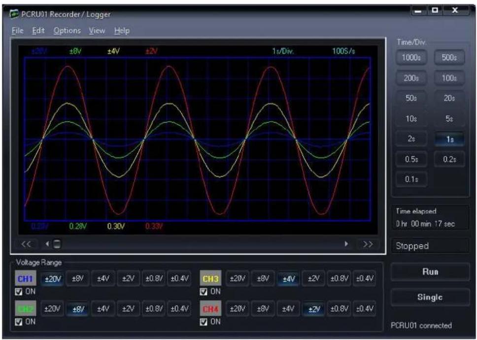
Using this screen the 4 channels can be viewed simultaneously as a trace on the screen
Digital screen
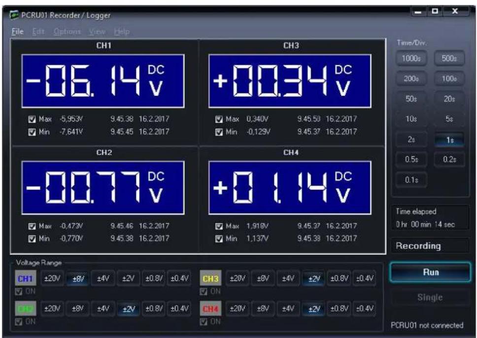
Powerful feature which allows digital visualisation of the measurements
Software controls
Analog readout
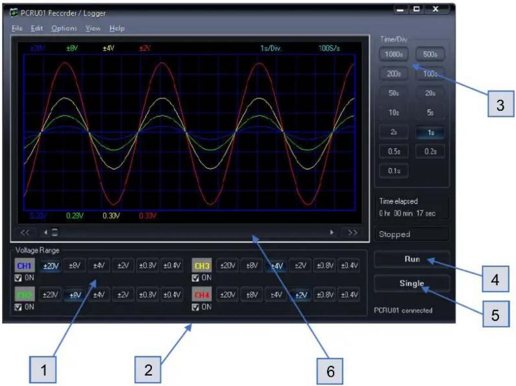
Voltage Range (1)
Selected value indicates the full measurement range.
ON Checkbox (2)
Turn the channels ON/OFF.
TIME/DIV (3)
Selects the time setting for the beam to sweep one major division on the screen.
Selection of TIME/DIV is possible to zoom in on the frozen waveform display.
RUN (4)
Selects recurrent display update mode (RUN). Pressing the button again freezes the display.
SINGLE (5)
When button is depressed refreshment of the display takes place only once.
X-POSITION SCROLLBAR (6)
Positions the trace horizontally on the screen.
Digital readout
Momentary voltage

Momentary voltage (1)
Shows the momentary measurement readout of the voltage.
Max. & Min. voltage storage (2)
When this option is selected, the signals max. / min. voltage values and the date & time are stored.
Menu options
File Menu
Open Image
Opens an image file and displays it on the screen.
Open Data
Opens and displays the waveform data saved in text format using the Save Data or AutoSave Data option.
Save Image
Saves the image to a file in PNG or in Windows Bitmap (BMP) format.
Save Data
Saves the waveform in text format. only the portion of the data displayed on the screen is saved.
AutoSave Data
Saves all next screens of data in text format to a file.
The AutoSave function will be activated after the Run button is pressed.
The AutoSave function will be finished after the Run button is pressed again.
Note: Every screen saved takes about 90kB of disk space
Prints the image.
You can edit the image caption.
Print Setup
Selects a printer and sets printer options before printing. The available options depend on the printer you select.
Exit
Terminates the program.
Use this option to restore all values to their default factory settings.
The calibration values will be reset.
Use this option if the recorder calibration fails repeatedly.
Note: Software reinstallation does not reset the recorder settings - you have to use this menu option to restore default settings.
Note: Default folder Documents\My PCRU01 for image and data files is created when the program is run for the first time.
Edit Menu
Copy
Copies the image to the Windows' clipboard.
Paste
Pastes the image residing in Windows' clipboard to the screen
Options Menu
Colors
Select the color for various items on the waveform display.
- To change the color of an item, click the corresponding button. This will open a dialog in which you can select the new color.
- Full color selection is possible only if True Color (24 bit) palette is used.
- There are restrictions in the color combinations with other palettes.
- Click Bright Screen or Black Screen button to resets all colors to the Default settings.
Calibrate
Makes the recorder calibration and saves the calibration values to the PCRU01.INI file.
Skins
Using this option you can give the software a new look by applying a different skin.
You can select the skin from set of seven alternatives.
View Menu
Markers dV & t
The absolute time of the marker position is displayed.
Two horizontal markers for measuring voltage.
Markers dV & dt
The time difference between the two markers is displayed.
Two horizontal markers for measuring voltage.
DVM display
Displays the digital screen recorder/logger.
Bright Grid
Brightens the grid on the screen.
Help Menu
Contents
Displays the help file.
About
Displays information of the program version.
Move the markers
- Place the mouse pointer over a dashed marker line.
- Press and hold the left mouse button.
• The marker line turns solid. - Drag the marker to the appropriate position.
Add comment text on the signal screen
For explanation and documentation, each measurement can be supplied with a comment text.
This text will be saved together with the waveform data to the disk file.
To enter the text
- Right mouse click into the screen.
- Text box will open, to write your comment.
- Click Add Text on Screen or Remove to remove previously inserted text.
- Right click on the screen to position your text.
- Click Close.
To make the text transparent with the background, check Transparent text.
The text will have the same color as the vertical time markers.
Troubleshooting
Errors in time scale
When recording at short timebase (<1s/div) the sampling interval is <10ms. This is possible only on fast computers. Anyhow, do not execute other applications during the recording process, it may influence the measuring time scale.
The timebase of the measurements is generated by the internal timer of the computer. This timer can be put on hold by other processes on the computer. This can cause a deviation in the time measurement.
To ensure the precision of the time measurement at short timebase:
- Use a fast computer.
- Do not run other applications when recording
- Use highest possible processor speed
- Prevent your computer from going into sleep or power saving mode
No signal
- No communication with the computer (check that the cable is connected to the USB port).
- If USB cable is connected, close the program. Disconnect and reconnect the USB cable and run the program again.
o RUN button is not ON.
- TIME/DIV switch is in the wrong setting, try 1s/div
- Input amplitude is too large, adjust VOLTS/DIV setting.
If the above tips have no effect, then test on a different computer or different USB port.
Note. Close the program before disconnecting the USB cable.
- Features
- Specifications
- hardware:
- software:
- system requirements:
- Software installation
- Starting the software:
- SAFETY and WARNINGS
- ATTENTION :
- Warranty
- Connections
- power led
- record indicator led
- Signal input
- Readout screens
- Software controls
- Analog readout
- Voltage Range (1)
- ON Checkbox (2)
- TIME/DIV (3)
- RUN (4)
- SINGLE (5)
- X-POSITION SCROLLBAR (6)
- Digital readout
- Momentary voltage
- Momentary voltage (1)
- Max. & Min. voltage storage (2)
- Menu options
- File Menu
- Open Image
- Open Data
- Save Image
- Save Data
- AutoSave Data
- Print Setup
- Exit
- Edit Menu
- Copy
- Paste
- Options Menu
- Colors
- Calibrate
- Skins
- View Menu
- Markers dV & t
- Markers dV & dt
- DVM display
- Bright Grid
- Help Menu
- Contents
- About
- Move the markers
- Add comment text on the signal screen
- To enter the text
- Troubleshooting
- Errors in time scale
- No signal
Brand : VELLEMAN
Model : PCRU01
Category : Measuring equipment