
DXC-C33P - Camcorder SONY - Free user manual and instructions
Find the device manual for free DXC-C33P SONY in PDF.


| Product Type | 3-CCD Professional Camcorder |
| Brand | Sony |
| Model | DXC-C33P |
| Dimensions (L x W x H) | 255 x 245 x 375 mm |
| Weight | 4.5 kg (without lens) |
| Power Supply | 12 V DC (battery or AC adapter) |
| Sensor | 3 CCD 1/3 inch |
| Resolution | 752 x 582 pixels (PAL) |
| Lens Mount | C/CS |
| Video Outputs | Composite, Y/C, RGB, Component |
| Signal-to-Noise Ratio | 62 dB |
| Gain | 0, 9, 18 dB |
| Shutter Speed | 1/50 to 1/10000 s |
| White Balance | Automatic, Preset, Manual |
| Main Features | 3-CCD video recording, digital zoom, electronic shutter function, genlock input/output, component video output |
| Maintenance and Cleaning | Clean the body with a dry soft cloth. Use a cleaning kit for optics. Do not use solvents. |
| Safety | Use only recommended accessories. Do not expose to moisture. Disconnect before maintenance. |
| Spare Parts and Repairability | Contact a Sony authorized service center. Some parts are available online. |
| Operating Temperature | 0 to 40 °C |
| Operating Humidity | 20 to 80 % (non-condensing) |
Frequently Asked Questions - DXC-C33P SONY
User questions about DXC-C33P SONY
0 question about this device. Answer the ones you know or ask your own.
Ask a new question about this device
Download the instructions for your Camcorder in PDF format for free! Find your manual DXC-C33P - SONY and take your electronic device back in hand. On this page are published all the documents necessary for the use of your device. DXC-C33P by SONY.
USER MANUAL DXC-C33P SONY
For Customer in China
Instructions for Use GB
Printed on recycled paper
Sony Corporation Printed in Japan
© 2001 Sony Corporation
Owner's Record
The model and serial numbers are located on the side. Record these numbers in the spaces provided below.
Refer to these numbers whenever you call upon your Sony dealer regarding this product.
Model No. Serial No.
WARNING
To prevent fire or shock hazard, do not expose the unit to rain or moisture.
To avoid electrical shock, do not open the cabinet. Refer servicing to qualified personnel only.
This apparatus must be earthed.
Symbol on the products

This symbol indicates the equipotential terminal which brings the various parts of a system to the same potential.
For the customers in the U.S.A.
This equipment has been tested and found to comply with the limits for a Class A digital device, pursuant to Part 15 of the FCC Rules. These limits are designed to provide reasonable protection against harmful interference when the equipment is operated in a commercial environment.
This equipment generates, uses, and can radiate radio frequency energy and, if not installed and used in accordance with the instruction manual, may cause harmful interference to radio communications.
Operation of this equipment in a residential area is likely to cause harmful interference in which case the user will be required to correct the interference at his own expense.
You are cautioned that any changes or modifications not expressly approved in this manual could void your authority to operate this equipment.
All interface cables used to connect peripherals must be shielded in order to comply with the limits for a digital device pursuant to Subpart B of Part 15 of FCC Rules.
WARNING on power connection
Use a proper power cord for your local power supply.
- Use the approved Power Cord (3-core mains lead) / Appliance Connector / Plug with earthing-contacts that conforms to the safety regulations of each country if applicable.
- Use the Power Cord (3-core mains lead) / Appliance Connector / Plug conforming to the proper ratings (Voltage, Ampere). If you have questions on the use of the above Power Cord / Appliance Connector / Plug, please consult a qualified service personnel.
WARNING on power connection for medical use
Please use the following power supply cord. With connectors (plug or female) and cord types other than those indicated in this table, use the power supply cord that is approved for use in your area.
| United States and Canada | |
| Plug Type HOSPITAL GRADE* | |
| Cord type Min. Type SJTMin. 18 AWG | |
| Minimum Rating for Plug and Appliance Couplers | 10A/125V |
| Safety Approval | UL Listed and CSA |
*Note: Grounding reliability can only be achieved when the equipment is connected to an equivalent receptacle marked ‘Hospital Only’ or ‘Hospital Grade’.
For the customers in the U.S.A. and Canada
Model DXC-C33 is Non-Patient Equipment. This unit cannot be used in the vicinity of patients.
* Patient Vicinity

For the customers in Canada (for DXC-C33)
This unit has been certified according to Standard CSA C22.2 NO.601.1.
For the customers in Europe (for DXC-C33P)
Important safeguards/notice for use in the medical environments
- All the equipment connected to this unit shall be certified according to Standard IEC60601-1, IEC60950-1, IEC60065 or other IEC/ISO Standards applicable to the equipment.
- Furthermore, all configurations shall comply with the system standard IEC60601-1-1. Everybody who connects additional equipment to the signal input part or signal output part configures a medical system, and is therefore responsible that the system complies with the requirements of the system standard IEC60601-1-1. If in doubt, consult the qualified service personnel.
This unit cannot be used in the patient environment.
* Patient Environment.

- Do not touch the patient simultaneously while you are in contact with this equipment.
- For this particular equipment, all accessory equipment connected as noted above must be connected to the mains via an additional isolation transformer that conforms to the construction requirements of IEC60601-1 and provides at least basic insulation.
- The leakage current could increase when connected to other equipment.
- This equipment generates, uses, and can radiate radio frequency energy. If it is not installed and used in accordance with the instruction manual, it may cause interference to other equipment. If this unit causes interference (which can be determined by unplugging the power cord from the unit), try these measures: Relocate the unit with respect to the susceptible equipment. Plug this unit and the susceptible equipment into different branch circuits.
Consult your dealer. (According to standard EN60601-1-2 and CISPR11, Class B, Group 1)
Caution
When you dispose of the unit or accessories, you must obey the law in the relative area or country and the regulations in the relative hospital.
Important EMC notices for use in medical environments
- The DXC-C33P needs special precautions regarding EMC and needs to be installed and put into service according to the EMC information provided in these instructions for use.
- Portable and mobile RF communications equipment, such as cellular phones, can affect the DXC-C33P.
| List of cables used for EMC tests | |
| Type of Cable Specifications | |
| AC mains cable 2.4 m, | non-shielded |
| 75-ohm coaxial cable 3 | m, shielded |
| CCMC-20P30 cable 30 | m, shielded |
| CCXC-9DB cable 3 m, | shielded |
| S-video cable 5.3 m, | shielded |
| i.LINK cable 3.5 m, | shielded |
| Camera cable 3 m, | shielded |
| Remote cable 2.1 m, | shielded |
Warning
The use of accessories and cables other than those specified, with the exception of replacement parts sold by Sony Corporation, may result in increased emissions or decreased immunity of the DXC-C33P.
| Guidance and manufacturer's declaration-electromagnetic emissions | ||
| The DXC-C33P is intended for use in the electromagnetic environment specified below.The customer or the user of the DXC-C33P should assure that it is used in such an environment. | ||
| Emission test Compliance Electromagnetic env | ironment-guidance | |
| RF emissionsCISPR 11 | Group 1 The DXC-C33P uses RF energy only for itsinternal function. Therefore, its RF emissionsare very low and are not likely to cause anyinterference in nearby electronic equipment. | |
| RF emissionsCISPR 11 | Class B The DXC-C33P is suitable for use in allestablishments, including domesticestablishments and those directly connected tothe public low-voltage power supply networkthat supplies buildings used for domesticpurposes. | |
| Harmonic emissionsIEC 61000-3-2 | Class A | |
| Voltage fluctuations/flicker emissionsIEC 61000-3-3 | Complies | |
Warning
If the DXC-C33P should be used adjacent to or stacked with other equipment, it should be observed to verify normal operation in the configuration in which it will be used.
| Guidance and manufacturer's declaration - electromagnetic immunity | |||
| The DXC-C33P is intended for use in the electromagnetic environment specified below. The customer or the user of the DXC-C33P should assure that it is used in such as environment. | |||
| Immunity test IEC | 60601 test level | Compliance level | Electromagnetic environment - guidance |
| Electrostatic discharge (ESD)IEC 61000-4-2 | ±6 kV contact±8 kV air | ±6 kV contact±8 kV air | Floors should be wood, concrete or ceramic tile. If floors are covered with synthetic material, the relative humidity should be at least 30%. |
| Electrical fast transient/burstIEC 61000-4-4 | ±2 kV for power supply lines±1 kV for input/output lines | ±2 kV for power supply lines±1 kV for input/output lines | Mains power quality should be that of a typical commercial or hospital environment. |
| SurgeIEC 61000-4-5 | ±1 kV differential mode±2 kV common mode | ±1 kV differential mode±2 kV common mode | Mains power quality should be that of a typical commercial or hospital environment. |
| Voltage dips, short interruptions and voltage variations on power supply input linesIEC 61000-4-11 | < 5% UT(>95% dip in UT) for 0.5 cycle40% UT(60% dip in UT) for 5 cycles70% UT(30% dip in UT) for 25 cycles< 5% UT(>95% dip in UT) for 5 sec | < 5% UT(>95% dip in UT) for 0.5 cycle40% UT(60% dip in UT) for 5 cycles70% UT(30% dip in UT) for 25 cycles< 5% UT(>95% dip in UT) for 5 sec | Mains power quality should be that of a typical commercial or hospital environment. If the user of the DXC-C33P requires continued operation during power mains interruptions, it is recommended that the DXC-C33P be powered from an uninterruptible power supply or a battery. |
| Power frequency (50/60Hz) magnetic fieldIEC 61000-4-8 | 3 A/m 3 A/m Power frequency magnetic fields should be at least characteristic of a typical location in a typical commercial or hospital environment. | ||
| NOTE: UT is the a.c. mains voltage prior to application of the test level. | |||
| Immunity test IE | C 60601 test level | Compliance level | Electromagnetic environment - guidance |
| Conducted RF | 3 Vrms | 3 Vrms | Portable and mobile RF communications equipment should be used no closer to any part of the DXC-C33P, including cables, than the recommended separation distance calculated from the equation appliance to the frequency of the transmitter.Recommended separation distance d = 1.2 d = 1.2 80MHzto 800MHz d = 2.3 800MHzto 2.5GHz P is the maximum output power rating of the transmitter in watts (W) according to the transmitter manufacturer and d is the recommended separation distance in meters (m).Field strengths from fixed RF transmitters, as determined by an electromagnetic site survey, a should be less than the compliance level in each frequency range. b Interference may occur in the vicinity of equipment marked with following symbol: |
| IEC 61000-4-6 | 150 kHz to 80 MHz | ||
| Radiated RF | 3 V/m | 3 V/m Where | |
| IEC 61000-4-3 | 80 MHz to 2.5 GHz | ||
| NOTE 1: At 80 MHz and 800 MHz, the higher frequency range applies.NOTE 2: These guidelines may not apply in all situations. Electromagnetic propagation is affected by absorption and reflection from structures, objects and people. | |||
| a Field strengths from fixed transmitters, such as base stations for radio (cellular/cordless) telephones and land mobile radios, amateur radio, AM and FM radio broadcast and TV broadcast cannot be predicted theoretically with accuracy. To assess the electromagnetic environment due to fixed RF transmitters, an electromagnetic site survey should be considered. If the measured field strength in the location in which the DXC-C33P is used exceeds the applicable RF compliance level above, the DXC-C33P should be observed to verify normal operation. If abnormal performance is observed, additional measures may be necessary, such as reorienting or relocating the DXC-C33P.b Over the frequency range 150 kHz to 80 MHz, field strengths should be less than 3 V/m.Recommended separation distances between portable and mobile RF communications equipment and the DXC-C33P | |||
| The DXC-C33P is intended for use in an electromagnetic environment in which radiated RF disturbances are controlled. The customer or the user of the DXC-C33P can help prevent electromagnetic interference by maintaining a minimum distance between portable and mobile RF communications equipment (Transmitters) and the DXC-C33P as recommended below, according to the maximum output power of the communications equipment. | |||
| Rated maximum output power of transmitter W | Separation distance according to frequency of transmitter m | ||
| 150 kHz to 80 MHz d = 1.2 | 80 MHz to 800 MHz d = 1.2 | 800 MHz to 2.5 GHz d = 2.3 | |
| 0.01 0.12 0.12 | 0.23 | ||
| 0.1 0.38 0.38 | 0.73 | ||
| 1 1.2 1.2 2.3 | |||
| 10 3.8 3.8 7.3 | |||
| 100 12 12 23 | |||
| For transmitters rated a maximum output power not listed above, the recommended separation distance d in meters (m) can be estimated using the equation applicable to the frequency of the transmitter, where P is the maximum output power rating of the transmitter in watts (W) according to the transmitter manufacturer.NOTE 1: At 80 MHz and 800 MHz, the separation distance for the higher frequency range applies.NOTE 2: These guidelines may not apply in all situations. Electromagnetic propagation is affected by absorption and reflection from structures, objects and people. | |||
Table of Contents
Overview
Features ....10
Location and Functions of Parts and Controls ....11
Camera Head 11
Camera Control Unit ......12
Adjusting and Setting With Menus
About On-screen Menus ....15
Operation Through Menus .....16
EXPOSURE Menu ....17
CONTRAST Menu 20
WHITE BALANCE Menu ......21
ENHANCER Menu ......23
GENERAL Menu 24
SYSTEM Menu 26
SCENE FILE Menu 27
Operation
Shooting 29
Basic Shooting Procedure .....29
Adjusting the Black Balance .....29
Adjusting the White Balance .....30
Adjusting the Picture Tone in a Multi-Camera System .....31
Installation and Connections
Installation 32
Applicable Lens ....32
Mounting the Lens ....32
Mounting a Microscope Adaptor 32
Mounting on a Tripod ....32
Attaching to a Wall or Ceiling ... 33
Connections 34
Connecting Between the Camera Head and Camera Control Unit 34
Connecting the AC Power Cord 34
Connecting to Video Equipment With Composite Video Input Connectors .... 35
Connecting to Video Equipment With S-Video Input Connector 35
Connecting to Video Equipment With RGB Inputs ...... 36
Connecting to Video Equipment With DV Input Connector 37
Connecting Two or More Cameras — Multi-Camera System 38
Connecting to a Remote Control Unit 39
Connecting to a Computer ...... 41
Connections for Shooting Using a Flash 42
Connections for Displaying a Freeze Picture Using a Foot Switch 43
Appendix
Precautions 44
Typical CCD Phenomena 44
List of Messages 45
WEN Pulse Timing Chart 46
Specifications 47
Menu Configuration 50
Features
High-quality images
- The high density 1/3 type, three-chip Exwave HAD™* CCD**, containing some 380,000 (DXC-C33) or 430,000 (DXC-C33P) effective picture elements (pixels), offers superior picture quality: 850 TV lines of high horizontal resolution, high sensitivity of F8 at 2,000 lx, an excellent signal-to-noise ratio of 62 dB (DXC-C33) or 61 dB (DXC-C33P) and a low smear level.
* Exwave HAD™: Exwave Hole-Accumulated Diode
"Exwave HAD™" is a trademark of Sony Corporation.
**CCD: Charge-Coupled Device
Precise picture control functions by the adoption of LSI digital signal processing technology
- DynaLatitude processing enables you to adjust contrast finely according to the luminance signal level of each picture element.
- The DCC+ (Dynamic Contrast Control plus) function minimizes the phenomena whereby the whole screen turns white or a part of the image becomes colorless when shooting a very bright object.
- The Partial Enhance function enables you to adjust the sharpness and tint of only a specified color.
Compact and lightweight Remote Camera Head System
- The camera head is compact (38 x 32 x 40 mm (1 1/2 x 1 5/16 x 1 5/8 inches)) and very light (48 g (1.7 oz)), allowing easy mounting on a device which was difficult to be mounted.
- Versatile use of the camera is realized by connecting the camera head and the camera control unit with the optional camera cable, which enables you to extend the connecting distance up to 30 m (98 feet).
i.LINK (DV) digital interface equipped
Connecting a DVCAM format digital video cassette recorder to this camera allows you to make easy digital recording.
Freeze and long term exposure functions
By utilizing the built-in one frame memory (10 bits), freeze function and long term exposure function can be easily controlled.
RS-232C interface
The camera can be controlled from a computer via the RS-232C interface. For details, contact your authorized Sony dealer.
Location and Functions of Parts and Controls
Camera Head

Lens Mount
Attach a C-mount lens or microscope adaptor.
Note
Be sure to use a lens whose projected part from the lens mount surface is less than 4.3 mm (3/16 inches). Mounting the lens with a projected part greater than 4.3 mm (3/16 inches) may damage the internal mechanism of the camera.
Camera cable connector (20-pin)
Connects to the CAMERA connector on the camera control unit with the optional CCMC-20P05/10/30 camera cable.
③ Screw holes
Use these holes (M3, depth: 3 mm (1/8 inches)) to attach the supplied tripod adaptor to the camera head for mounting the camera head on a wall, ceiling, or tripod.
Camera Control Unit
Front
Rear
① (power) switch and indicator
Press the switch down to turn on the power of the unit. The indicator lights in green. To turn off the power, press the switch again. The indicator turns off.
Note
Be sure to connect the camera head and camera control unit with the camera cable (not supplied) before you turn the camera on or off.
② FREEZE button and indicator
Pressing this button stores an image in the built-in frame memory and outputs it as a freeze picture. When the freeze picture mode activates, the indicator lights. Pressing the button again turns off the indicator and cancels the freeze picture mode. The image currently shot is displayed on a monitor screen.
③ ←/FILE SELECT button
While the menu is displayed:
Decreases the setting value or changes the setting. Also use this button for an AE window setting, etc.
While the normal screen is displayed: Switches the user preset file between A and B.
④↑/BLACK (black balance) button
While the menu is displayed: Moves the menu cursor upward. Also use this button for an AE window setting, etc.
While the normal screen is displayed: Activates the automatic black balance adjustment.
⑤→/ WHITE (white balance) button
While the menu is displayed: Increases the setting value or changes the setting. Also use this button for an AE window setting, etc.
While the normal screen is displayed: Activates the automatic white balance adjustment when MODE is set to AWB in WHITE BALANCE menu.
⑥MENU button
Displays the MAIN menu on a monitor screen. Press again to exit the menu. When a setting menu is displayed, press this button to return to the MAIN menu.
For menu operations, see “Operation Through Menus” on page 16.
⑦ ENTER button
Selects a setting menu in the MAIN menu. Also use this button for an AE window setting, etc.
⑧ AE AREA SELECT button
Selects the AE window set with the menu. Each press of the button selects the AE AREA 1 or AE AREA 2. The selected AE area is displayed on a monitor screen for about a second.
Note
The button functions only when GAIN is set to AGC or SHUTTER is set to CCD-IRIS.
⑨ LOCK button and indicator
When you press this button to make the indicator light, no buttons on the camera control unit except for the ① (power) switch function. Pressing the button again turns off the indicator and cancels lock mode. You can use any button. The lock mode retains after the unit is turned off.
10 AE LEVEL control
Adjusts the auto exposure focusing point when the camera is set to AGC or CCD-IRIS mode. Turning the control clockwise increases the value, and turning it counterclockwise decreases the value.
When SHUTTER is set to KNOB, the shutter speed and video gain can be adjusted with this control. Turning it counterclockwise adjusts the shutter speed. Turning it clockwise adjusts the video gain. In KNOB setting, the △ GAIN control does not function.
⑪ GAIN RED/BLUE controls
Use these controls for fine adjustment of white balance when AWB or ATW mode is selected. Also use them to adjust the red and blue gain when adjusting the white balance manually. Turning the control clockwise sets to the positive levels. Turning it counterclockwise sets to the negative levels.
12 GAIN control
Adjusts the gain level. Turning the control adjusts the level in the range from 0 to 24 dB.
13↓ button
Moves the menu cursor downward. Also use this button for an AE window setting, etc.
⑭BARS (color bars output) button
Outputs the color bar signal. Press again to revert to video signal output.
For monitor adjustment, contact your authorized Sony dealer.
⑮CAMERA connector (20-pin)
Connects to the camera cable connector on the camera head using the CCMC-20P05/10/30 camera cable (not supplied).
16 VIDEO OUTPUT connector (BNC type)
Outputs a composite video signal.
⑰ i* DV connector (6-pin)
The connector is especially designed to output signals in DV format that complies with i.LINK. Used to connect the video equipment equipped with the i DV connector.
* is a trademark of Sony Corporation and indicates that this product is in agreement with IEEE1394–1995 specifications and their revisions.
18FS/TRIG IN (Foot Switch/Trigger input) connector (stereo minijack)
Connects the optional foot switch. When the camera is in strobe mode, connects a commercially available slave unit.
Note
The foot switch must comply with Standard UL2601-1/EN60601-1.
For details on the foot switch, consult with an authorized Sony dealer.
19EXT SYNC (external sync) (HD, VD/SYNC) connectors (BNC type)
Inputs reference sync signals for synchronizing the camera operation. When using the internal sync signals, outputs the HD/VD or composite sync signals.
⑳ Equipotential ground terminal
Used to connect with the equipotential plug to bring the various parts of a system to the same potential.
Refer to “Important safeguards/notice for use in the medical environments” on page 3.
21~ AC IN socket
Connects the supplied AC power cord.
22 REMOTE connector (mini DIN 8-pin)
Connects to the RM-C950 remote control unit (not supplied).
23 RGB/SYNC connector (D-sub 9-pin)
Outputs RGB signals and their respective sync signals.
24 S·VIDEO OUTPUT connector (mini DIN 4-pin)
Outputs an S video (Y/C video) signal.
Adjusting and Setting With Menus
About On-screen Menus
Camera operational settings can be changed through simple adjustment of the settings on the on-screen menus.
This section explains how to read the on-screen menu before starting menu operation.
For the menu configuration of the camera, see page 50.
MAIN Menu![>EXPOSURE CONTRAST WHITE BALANCE ENHANCER GENERAL SYSTEM SCENE FILE RM [A] Select ENTER Next MENU Exit](/content/2026/06/1396081/images/6a57ffedf96ce59a5edf7ae4f8d7b30f82defd9ed639f19cf57c685f510ca48a.jpg)
① Cursor
Selects a setting menu or setting item. Move the cursor up or down using the ↑ or ↓ button.
②Setting menu items
When you select the desired item with the ↑ or ↓ button and press the ENTER button, the setting menu for adjustment and setting is displayed.
③Remote control unit indicator
Indicates when the RM-C950 remote control unit is connected to the ↗ REMOTE connector on the rear of the camera control unit.
④User preset file
You can store two types of preset adjustments into files A and B. Indicates the currently selected preset file (A or B).
For details, see "SCENE FILE Menu" on page 27.
⑤Operational message
Indicates how to operate the currently displayed menu.
Setting Menu![>GAIN STEP SHUTTER RM [A] STEP 0dB OFF Select NEW Back](/content/2026/06/1396081/images/197eb9c38ab7c4ea5aa25314591d95ae4d83f98538c9e454ce18ca86628e5a20.jpg)
①Setting menu
Indicates the currently selected setting menu.
② Setting items
Indicates the items that can be adjusted in each setting menu. Select the item by moving the cursor beside it with the ↑ or ↓ button.
③ Set values
The currently set values are displayed. Change the values using the ◀ or ➤ button.
For the initial set value on each item, see "Menu Configuration" on page 50.
Operation Through Menus
To change the settings on the menu, proceed as follows.
Some of the settings, however, cannot be adjusted on the menu. Use the controls on the front of the camera control unit to adjust them.
For details, see page 17.
Note
Before starting menu operation, make sure that the LOCK indicator on the front of the camera control unit is not lit. When it is lit, the menu will not be displayed even if you press the ⓂMENU button. If the LOCK indicator lights, press the LOCK button to turn the indicator off, then operate the menu.

1 Press the MENU button. The MAIN menu appears.
![[A] >EXPOSURE CONTRAST WHITE BALANCE ENHANCER GENERAL SYSTEM SCENE FILE Select Enter Next Exit](/content/2026/06/1396081/images/a626bf607574d4a73fadb71f932231cc768b6cefc9669ea862d22e9bfec8e9b2.jpg)
2 Move the cursor to the menu item to be set by pressing the ↑ or ↓ button, then press the ENTER button. The setting menu is displayed.
![[A] >GAIN STEP STEP 0dB SHUTTER OFF ▲▼▼ Select ▼EW Back](/content/2026/06/1396081/images/f702417a7a26749ebc2d82aef9ea4415817cac9ce7639abf7865f275c31ff78e.jpg)
3 Move the cursor to the item to be adjusted by pressing the ↑ or ↓ button.
![[A] GAIN STEP STEP 0dB >SHUTTER OFF Select VEN Back](/content/2026/06/1396081/images/7fde6e6ca802ad7437c86bb53bc8b2ef4f6a4a02093ab6013e4a44a7ccd734de.jpg)
4 Change the value by pressing the ◀ or ▶ button. Holding down the button changes the value quickly.
![[A] GAIN STEP STEP 0dB >SHUTTER STEP SPEED OFF ▲▼▼▼ Select ▼▼▼ Back](/content/2026/06/1396081/images/ccfdec01fca7839269c3f12f0fcbd2fbe205e6495fce803639738f41cbf8afd3.jpg)
To reset to the initial set value
Select the item to be reset, then press the ◀ and ➤ buttons simultaneously.
For the initial set value on each item, see "Menu Configuration" on page 50.
To return to the normal screen
Press the MENU button while the MAIN menu is displayed.
While each setting menu is displayed, press the ⓂMENU button to return to the MAIN menu, then press it again to return to the normal screen.
Adjusting the Setting Items With the Controls on the Front of the Camera Control Unit
Use the controls on the front of the camera control unit to adjust some of the setting items such as gain and white balance.
For details on setting individual items, see the relevant menu pages.

EXPOSURE Menu
The EXPOSURE menu is used to adjust the items relating to exposure, such as gain and shutter mode.
![[A] >GAIN STEP STEP 0dB SHUTTER OFF AE SETUP AE LEVEL ± 0 *AE AREA1 MULTI AE AREA2 MULTI Select MENU Back](/content/2026/06/1396081/images/aea3b23798b93ee444e463f90596b2a2b05ae97ba060af05c4958dcb0d30266b.jpg)
GAIN
Adjusts the video gain.
STEP
Select to set the video gain to the desired level.
STEP
Adjust the gain level by turning the △ GAIN control on the camera unit control. The set value for STEP in the menu changes to the adjusted level. The adjustable level is within the range from 0 to 24 dB. You cannot adjust it using the menu.
AGC
Automatically adjusts the gain according to the brightness of the object to be shot (Automatic gain control).
LIMIT
Selects the maximum gain level to be adjusted to 6, 12, 18 or 24 dB.
HYPER
Increases the video gain to about 30 dB.
SHUTTER
Selects the electronic shutter modes.
OFF
Any electronic shutter mode does not function.
STEP
Select to set the shutter speed to any of 4 steps in long-exposure mode and 15 steps in high-speed mode.
SPEED
Sets the shutter speed.
To set the shutter speed
1 Select SPEED by pressing the ↑ or ↓ button. 2 Display OFF by pressing the ← and → buttons simultaneously. 3 Press the ← button to set the speed for long-exposure mode, or press the → button to set it for high-speed mode. 4 Each press changes the shutter speed.
VARIABLE
Use for fine adjustment of the video output level in units of 1 frame (long exposure mode) or in units of 1H (horizontal scanning time: 63.56 μs for DXC-C33, 64.00 μs for DXC-C33P) (clear scan mode).
In long exposure mode, for example, if you set to 10 frames (about 0.33 seconds), the video signal produced during this set time is output in the form of one complete frame at intervals of about 0.33 seconds. These pictures, which contain 10 frames of video information, are much brighter than normal one-frame images. This mode is useful for shooting a poorly illuminated object in a dark place.
The clear scan mode can be used for shooting computer displays with reduced horizontal bands appearing across the display screen. Adjust the value while observing the noise on the monitor screen so that you can obtain the image with minimum noise.
SPEED
Sets the shutter speed.
To set the shutter speed
1 Select SPEED by pressing the ↑ or ↓ button. 2 Display OFF by pressing the ← and → buttons simultaneously. 3 Press the ◀ button to set the speed for long-exposure mode, or press the ➤ button to set it for clear scan mode. 4 Each press changes the shutter speed.
To convert the value into the shutter speed
Long-exposure mode
Example: When the value is set to 5 frames 5 × 1/30 = 0.1666 seconds (DXC-C33) 5 × 1/25 = 0.2000 seconds (DXC-C33P)
Clear scan mode
Example: When the value is set to 250H DXC-C33: 250 × 63.56 µs (1H) + 34.9 µs (constant) = 15924.9 µs = Approx. 0.016 seconds DXC-C33P: 250 × 64.00 µs (1H) + 35.0 µs (constant) = 16035.0 µs = Approx. 0.016 seconds.
Note
Do not use AGC, CCD-IRIS, ATW, AWB DCC+ and DYNALATITUDE functions in long exposure mode.
Set the gain level to 0 dB.
CCD-IRIS
Automatically adjusts the luminance level for optimum output level. When incoming light is excessive, this function automatically adjusts the shutter speed to cut exposure equivalent to up to 10 aperture stops.
LIMIT
Sets the maximum shutter speed to be adjusted to 1/250, 1/500, 1/1000, 1/2000, 1/4000, 1/10000, 1/20000, 1/40000 or 1/100000.
KNOB
You can adjust the shutter speed and video gain with the AE LEVEL control on the front of the camera control unit. With this setting, GAIN is locked to STEP and the GAIN control does not function.
When the RM-C950 remote control unit is connected, you can use the IRIS control on the remote control unit to adjust the shutter speed and video gain.
AE SETUP
Adjusts the auto exposure focusing point and selects the AE (Auto Exposure) window when the camera is set to AGC or CCD IRIS mode.
Note
The setting items for AE SETUP are displayed only when GAIN is set to AGC or SHUTTER is set to CCD-IRIS.
AE LEVEL
Adjust the auto exposure focusing point by turning the AE LEVEL control on the camera control unit. The set value for AE LEVEL in the menu changes to the adjusted level. The adjustable level is within the range from -127 to +127. You cannot adjust it with the menu.
AE AREA1/AE AREA2
Selects the AE window when the camera is set to AGC or CCD IRIS mode.
When a different AE window is set to each of AE AREA 1 and 2, you can select either by pressing the AE AREA SELECT button on the camera control unit. The * mark appears beside the selected AE AREA in the menu. When the button is pressed while the menu is not displayed, the selected AE window is displayed on the monitor screen for about a second.
MULTI: Divides the screen into 9 sections and adjusts auto exposure according to the luminance level in each section. Normally set to this position.
LARGE, MID, SPOT and SLIT:
Displays the following AE windows and adjusts auto exposure according to the luminance level in each area. If the object you are shooting is very small, you can see it brighter with this setting to SPOT.

MANUAL: Sets the AE window manually with the desired size and position on the screen. Follow the steps below.
1 Select MANUAL and press the ENTER button.

2 Move the cross cursor appearing at the left top corner with the left, right, up, or down button to set the upper and left side size, then press the ENTER button.

3 Move the cross cursor appearing at the right bottom corner with the left, right, up, or down button to set the lower and right side size, then press the ENTER button.

4 Move the AE window to the desired position with the left, right, up, or down button, then press the ENTER button.
Note
To cancel the setting before completing the procedure, press the MENU button.
AE SPEED
Appears when you set AE AREA1 or 2 to an option other than MULTI.
Sets auto exposure focusing speed in AGC or CCD IRIS mode. Selects from MID (normal speed), FAST (fast speed) and SLOW (slow speed).
Note
If lens hunting occurs, adjust with AE SPEED.
AE DETECT
Appears when you set AE AREA1 or 2 to an option other than MULTI.
Selects the detection method of the luminance level of the selected AE window.
AVERAGE: Selects to detect the average luminance level of the whole AE window.
PEAK: Selects to detect the part with the highest luminance level.
CONTRAST Menu
The CONTRAST menu is used to adjust the contrast of the image.
![[A] > EFFECT MANUAL. KNEE POINT MID. BLACK STRETCH ± 0. GAMMA ON. LEVEL ± 0. MASTER PEDESTAL ± 0. R. PEDESTAL ± 0. B. PEDESTAL ± 0. ▼▼▼ Select, VENU Back.](/content/2026/06/1396081/images/c7e52358129d7e057c9e7cfcc6ff0a93ace3e13f5f28c151eb5d34f754d9ea97.jpg)
EFFECT
Selects the setting suitable for the incident luminance levels.
MANUAL
Selects KNEE POINT setting or BLACK STRETCH.
KNEE POINT
Sets the knee point according to the incoming light levels.
OFF: Knee processing does not function.
HIGH: Sets the knee point to the highest level.
MID: Normally, select this position.
LOW: Sets the knee point to the lowest level.
BLACK STRETCH
Adjusts the luminance of the dark portion of the screen.
You can set the value within the range from -10 to +10. The higher the setting, the brighter the screen.
DCC+ (Dynamic Contrast Control +)
When shooting a very bright object, the whole screen may white out or a part of the image may be colorless. This setting minimizes these phenomena.
DYNALATITUDE
Adjusts the contrast according to the luminance level of each picture element. The setting is useful for shooting scenes mixed with bright and dark parts. You can set the level within the range from -10 to +10.
GAMMA
Activates gamma compensation.
OFF
Outputs the video signal linearly without gamma compensation. Use this setting when you want to produce images for image processing or image analysis.
ON
Compensates the reproduction characteristics of a cathode-ray tube of a monitor to produce natural-tone image.
LEVEL
Adjusts gamma so that you can obtain natural-tone image. Adjustable range is from -10 to +10.
MASTER PEDESTAL
The pedestal levels of the G, B and R output signals can be adjusted simultaneously. Adjusts the darkness level of the black part of the image. Use this function to bring out details in heavily shaded areas. Use of a waveform monitor allows easier adjustment. The adjustable range is from -127 to +127. The whole screen becomes whiter when you adjust the level in the direction of +. The whole screen becomes blacker when you adjust the level in the direction of -. Normally set to ±0.
R. (red) PEDESTAL, B. (blue) PEDESTAL
Use these items to finely adjust the pedestal level of each color. Adjust them while watching the monitor screen. The items can be finely adjusted within the range from -127 to +127.
WHITE BALANCE Menu
The WHITE BALANCE menu is used to adjust the white balance.
![[A] > MODE AWB. R. PAINT ± 0. B. PAINT ± 0. AREA NORMAL. Select Black.](/content/2026/06/1396081/images/d05c4424823fa9f50e96f38aaf52bd1b02539a825c81db471ca8094da092f8a9.jpg)
MODE
Selects the white balance modes.
Select to adjust the white balance automatically (auto white balance).
R. (red) PAINT, B. (blue) PAINT
Use the GAIN RED or BLUE control on the camera control unit to make fine adjustments. Finely adjusts the red or blue in the range from -100 to +100. Adjust them while watching the monitor screen. When adjusted, the set values change to the adjusted levels.
For details, see "Adjusting the White Balance" on page 30.
AREA
A detecting window appears on the monitor screen. Normally set to NORMAL. If you want to display the desired window, set to MANUAL and follow the steps below.
1 Press the ENTER button. 2 Move the left top cross cursor with the left, right, up, or down button to set the upper and left side size, and press the ENTER button. 3 Move the right bottom cross cursor with the left, right, up, or down button to set the lower and right side size, and press the ENTER button.
4 Move the window to the desired position on the screen with the left, right, up, or down button, and press the ENTER button.
ATW NORMAL/ATW WIDE
Activates auto-tracing white balance. The white balance is automatically adjusted as the color temperature changes.
These modes are suitable for shooting when the light source changes.
Normally, set to ATW NORMAL.
The ATW WIDE setting can cope with a wider range of color temperature changes.
R. PAINT, B. PAINT
Use the GAIN RED or BLUE controls on the camera control unit to make fine adjustments. Finely adjust the red or blue in the range from -10 to +10. Adjust them while watching the monitor screen. When adjusted, the set values change to the adjusted levels.
The adjusted values are stored in memory separately from AWB values.
AREA
A detecting window appears on the monitor screen. The setting procedure is the same as that in AWB.
With NORMAL option, a detecting window is displayed on the whole screen.
SPEED
Sets the focusing speed. You can select SLOW (slow speed), MID (normal speed) or FAST (fast speed).
MANUAL
Use for manual adjustment of white balance.
R. GAIN, B. GAIN
Use the GAIN RED or BLUE controls on the camera control unit to adjust the red or blue gain. The adjustable level is within the range from -127 to +127. Adjust them while watching the monitor screen. When adjusted, the set values change to the adjusted levels.
3200K
Selects for indoor shooting. (Color temperature: 3200K)
5600K
Selects for outdoor shooting. (Color temperature: 5600K)
ENHANCER Menu
The ENHANCER menu is used to adjust the sharpness of the image outline and the color tone (hue).
![[A] > DETAIL ALL. LEVEL ± 0. FREQUENCY MID. LINEAR MATRIX ALL. MODE STANDARD. Select WENLCK.](/content/2026/06/1396081/images/e663a976fca73183ac5aee302bc02f5f0c6a55295ba4a10c36514b4319a0069c.jpg)
DETAIL
Enables or disables adjustment of the sharpness of the image outline.
ALL
Enables adjustment of the sharpness of the image outline.
LEVEL
Adjusts the level in the range from -127 to +127.
The lower level decreases the sharpness of the image outline and makes the image softer.
The higher level increases the sharpness of the image outline and makes the image sharper.
When the RM-C950 remote control unit is connected, this item is not adjusted with the menu. Adjust it using the control on the RM-C950.
FREQUENCY
Selects the frequency level with which the image outline is adjusted from LOW (lower frequency level), MID (middle frequency level) or HIGH (higher frequency level).
Higher setting provides a sharper outline of detailed images.
TARGET
Adjusts the image outline for a specific color.
When you set DETAIL to TARGET, TARGET COLOR appears. Specify the colors you want to adjust.
OFF
Disables adjustment of the sharpness of the image outline.
LINEAR MATRIX
Processes an image with a color matrix to change the chroma saturation and hue in order to reproduce natural color.
ALL
Corrects the color to reproduce natural color.
MODE
Adjusts the color suitable for the subject.
STANDARD: Normally, select this setting.
R ENHANCE: Enhances the red.
B ENHANCE: Enhances the blue.
G ENHANCE: Enhances the green.
MANUAL: Adjusts each color finely. The following options appear.
R. PAINT: Finely adjusts the red in the range from -30 to +30.
G. PAINT: Finely adjusts the green in the range from -30 to +30.
B. PAINT: Finely adjusts the blue in the range from -30 to +30.
TARGET
Corrects the color for a specific color. When you set LINEAR MATRIX to TARGET, TARGET COLOR appears. Specify the colors you want to adjust.
OFF
Color correction does not function. Use when you want to process the image.
TARGET COLOR
Select when adjusting DETAIL or LINEAR MATRIX for a specific color.
This item is displayed only when you set either DETAIL or LINEAR MATRIX to TARGET.
ALL
Adjusts DETAIL or LINEAR MATRIX for the whole image. Normally, set to this position.
IN
Adjusts DETAIL or LINEAR MATRIX for a specific color.
RANGE
Finely adjusts the area in the range from -10 to +10.
To specify a color
1 Press the ENTER button. 2 Move the cross cursor ( ) appearing in the center of the screen to the desired color with the left, right, up or down button so that the cross cursor square covers the desired color. You can adjust the color indicated by the cross cursor ( ) 3 Press the ENTER button. The screen returns to the menu display. To cancel the setting before completing the procedure, press the MENU button.
OUT
Adjusts DETAIL or LINEAR MATRIX for colors other than a specified color.
RANGE
Finely adjusts the area in the range from -10 to +10.
When you select OUT, then set the color with the procedure in "To specify a color," you can adjust DETAIL or LINEAR MATRIX for colors other than that indicated by the cross cursor ( ☐)
GENERAL Menu
The GENERAL menu is used to set the general items.
| GENERAL> | [A] |
| >CCD MODE | FIELD |
| SHADING COMP. | OFF |
| FS/TRIG IN | OFF |
| NEGA | OFF |
| FLICKER CANCELLER | OFF |
| Select Breakout | |
CCD MODE
Selects the CCD read-out mode.
FIELD
Accumulates charges in field units. Use to shoot a moving object.
FRAME
Accumulates charges in frame units. Provides the image with the highest possible vertical resolution. Use to shoot a still object.
SHADING COMP. (Shading Compensation)
Eliminates green or magenta color which may appear at the top or bottom of the screen, when the camera is used with an optical instrument.
OFF
Color elimination does not function.
ON
If green or magenta color appears at the top or bottom of the screen when the camera is attached to a microscope, etc., select this setting.
LEVEL
Adjusts the level within the range from -127 to +127. Adjust while watching the screen so that the color is eliminated.
+: Green at the top and magenta at the bottom will be eliminated. -: Magenta at the top and green at the bottom will be eliminated.
FS/TRIG IN (Foot Switch/Target Input)
Selects the input signal from the BS/TRIG IN connector.
OFF
Select when neither a slave unit nor foot switch is connected.
FS
Select when an optional foot switch is connected. Turning the foot switch on or off alternately outputs a freeze picture and the image currently being shot.
TRIGGER
Select when a slave unit is connected to synchronize the camera with a stroboscope. Each time a trigger pulse is input, the freeze picture changes.
When TRIGGER is selected, you cannot output an image as a freeze picture using the FREEZE button on the camera control unit.
POLARITY
Selects the same polarity as that of the pulse signal input.
: Falling edge L : Rising edge
Note
When FS/TRIG IN is set to TRIGGER or FS, AGC, CCD IRIS, ATW, AWB, DCC+ and DYNALATITUDE modes do not function.
NEGA
Reverses the output image to negative/positive.
OFF
Outputs the image normally.
ON
Outputs the image reversed to negative/positive.
FLICKER CANCELLER
When using the camera in a 50 Hz lighting area (DXC-C33) or in a 60 Hz lighting area (DXC-C33P), you can obtain images with less flicker under fluorescent light even when SHUTTER is set to CCD IRIS or OFF.
Set this item to OFF when you want to set NEGA to ON.
OFF
Disables the FLICKER CANCELLER function.
ON
Reduces flicker under fluorescent light.
SYSTEM Menu
The SYSTEM menu is used to set the items relating to the system of the camera and selection of output signals.
| <SYSTEM> | [A] |
| >BAUD RATE | 9600 |
| D-SUB VIDEO | VBS |
| D-SUB SYNC | C.SYNC |
| RGB SYNC | G |
| EXT SYNC | IN |
BAUD RATE
Switches the baud rate of the REMOTE connector. Sets to any of 19200, 9600, 4800, 2400 and 1200. Set to 9600 when the RM-C950 remote control unit is connected.
D-SUB VIDEO
Selects the VBS or Y/C signal output from the RGB/SYNC connector (D-sub 9-pin).
D-SUB SYNC
Selects the sync signal output from the RGB/SYNC connector (D-sub 9-pin).
C. SYNC
Outputs the composite sync signal.
WEN-ODD/WEN-EVEN/WEN-NORM
Outputs the WEN signal. When connecting peripheral equipment, the signal is used as trigger pulse output to the equipment. Switching WEN-ODD or WEN-EVEN provides a different pulse signal phase.
For the timing chart of the WEN pulse signal for each setting, see page 46.
POLARITY
Selects the polarity of the pulse signal. V : Negative R : Positive
RGB SYNC
Adds a sync signal to the G signal or R, G and B signals output from the RGB/SYNC connector.
OFF
No sync signal is added to an output signal.
G
Adds a sync signal to the G signal output from the RGB/SYNC connector.
RGB
Adds sync signals to the G, B and R signals output from the RGB/SYNC connector.
EXT SYNC
Switches the input and output of the EXT SYNC (HD, VD/SYNC) jacks (BNC type) and selects the output signal.
IN
Functions as the input jack.
When an external sync signal (VBS signal) is input, the following items appear: Adjusts the horizontal phase and SC (subcarrier) phase to synchronize the camera operation with the reference signal.
H. PHASE
Adjusts the horizontal phase within the range from -20 to +127.
SC. PHASE ROUGH
Roughly adjusts the subcarrier phase by setting to 0° or 180° .
SC. PHASE FINE
Finely adjusts the subcarrier phase within the range from -127 to +127.
When an external sync signal (HD/VD signal) is input, the following items appear: Adjusts the horizontal phase to synchronize the camera operation with the reference signal.
H. PHASE
Adjust the level within the range from -20 to +127.
Note
Turn on the external sync signal generator after all equipment is switched on.
OUT
Functions as the output jack.
SIGNAL
Selects the output signal from the EXT SYNC jacks.
HD/VD: Outputs the HD/VD signal.
C. SYNC: Outputs the composite sync signal.
SCENE FILE Menu
The SCENE FILE is used to set the preset menu settings.
The camera has two memory files (A or B) for storing the menu settings. You can store a different type of setting into each file, and switch to the file most suitable for the shooting conditions quickly. The currently selected memory file is shown in the upper right corner of the on-screen menu.
![[A] > FILE SELECT A. LOAD. ✓✓✓ Select Breakout.](/content/2026/06/1396081/images/3c47902a22b7008cd1d4b4fccc49e9cdb2d6a40e2d63455875baf7e859049bc0.jpg)
FILE SELECT
Selects the file A or B.
LOAD
Selects the setting to be stored into the file you select with FILE SELECT, and stores the setting.
STANDARD: Suitable for a camera used as a permanent fixture.
MICROSCOPE: Suitable for a camera for a microscope.
FULL AUTO: Automatically adjusts settings.
STROBE: Suitable for stroboscopic shooting.
FILE B (or A): When copying the settings between two files.
To store the setting
1 Select A or B into which the setting is stored in the FILE SELECT setting. 2 Press the up or down button to select LOAD. 3 Press the left or right button to select the desired setting to be stored, and press the ENTER button. "Overwrite OK?" appears. 4 Press the ENTER button. If you do not want to store the setting, press the MENU button.
Shooting
Basic Shooting Procedure

1 Press down the power switch on the camera control unit to turn on the power. The power indicator lights in green. 2 Turn on the powers of the connected devices. 3 Adjust the black balance.
For details, see "Adjusting the Black Balance" on the right column.
4 Illuminate an object with proper lighting. 5 Aim the camera to the object and adjust the iris, focus and zoom. 6 Adjust the white balance.
For details, see "Adjusting the White Balance" on page 30.
7 Adjust the settings as required.
For details, see "Adjusting and Setting With Menus" on page 15.
8 Start shooting.
Adjusting the Black Balance
Adjust the black balance first, after turning on the power of your camera.

1 If any menu is displayed on the screen, press the MENU button to remove it. 2 If a color bar signal is displayed on the screen, press the BARS button to remove it. 3 Press the BLACK button.
Close the iris before pressing the button. The black balance is automatically adjusted.
While adjusting, the bars are displayed. When the adjustment is completed, the message “BLACK: OK” appears on the screen.
Black balance adjustment errors
If the black balance adjustment is not successful, the message “BLACK: NG” appears on the screen. If this happens, take the necessary measures and perform steps 1 through 3 again.
For details, see "List of Messages" on page 45.
Adjusting the White Balance
Each time the lighting condition changes, be sure to adjust the white balance so that optimum color reproduction is obtained.

1 Press the MENU button to display the MAIN menu. 2 Select the WHITE BALANCE menu, and set MODE to AWB.
![[A] > MODE AWB. R. PAINT ± 0. B. PAINT ± 0. AREA NORMAL. Select BACK.](/content/2026/06/1396081/images/9e32f544866d2f803ac83755bcfa025dd6b39d374c2ea23a6a81163a6552f439.jpg)
For menu operation, see “Operation Through Menus” on page 16.
3 Select AREA with the ↑ or ↓ button and then set it to NORMAL with the ← or → button.
A detecting window appears.
![[A] MODE AWB. R. PAINT ± 0. B. PAINT ± 0. > AREA NORMAL. Select VEN Back.](/content/2026/06/1396081/images/3b3c26bf74f083818a05496d88ad7badb71784307ed91c7c3cd440e1e0141544.jpg)
For more details, refer to “WHITE BALANCE Menu” on page 21.
4 Display the camera image on the monitor screen.
Note
If a color bar signal is displayed on the screen, press the BARS button to turn it off.
5 Set the lens iris control to the appropriate opening value.
6 Place a white object (white pattern, white cloth, etc.) under the same light condition as that falling on the object to be shot, then zoom in on the white object to fill the detecting window on the screen.
Notes
- Do not include highly reflective objects in the picture. • Always shoot the image under suitable lighting conditions.
7 Press the MENU button twice to remove the menu. 8 Press the WHITE button.
During adjustment the bars appear. The message “WHITE: OK” appears on the screen when the adjustment is done.
The adjusted white level is automatically stored in memory and remains even if the power of the camera is turned off.
To shoot under the same conditions, the stored white balance is recalled by setting MODE to AWB in the WHITE BALANCE menu.
White balance adjustment errors
If the auto white balance adjustment is not successful, an error message appears on the screen. If this happens, take the necessary measures and perform steps 1 through 8 again.
For more details, see “List of Messages” on page 45.

Adjusting the Picture Tone in a Multi-Camera System
When configuring a multi-camera system, adjust all cameras to prevent camera-to-camera variations in picture tone. Before making the adjustments outlined below, input the same sync signal to all cameras.
For connections, see “Connecting Two or More Cameras — Multi-Camera System” on page 38.
Connecting the cameras to video equipment with phase indication capability
When connecting to a special-effects generator, a chroma-key unit, or other video equipment with phase indication capability, the basic adjustment procedure is as follows:
1 Turn on the phase indication capability of the connected video equipment. 2 Select H. PHASE from EXT SYNC in the SYSTEM menu, and adjust the horizontal phase.
For more details, see "SYSTEM Menu" on page 26.
3 Select SC. PHASE from EXT SYNC in the SYSTEM menu, and adjust the subcarrier phase.
First adjust the subcarrier phase roughly with SC. PHASE ROUGH set to 0° and 180° , then adjust it finely using SC. PHASE FINE.
For more details, refer to the instruction manual of the connected video equipment with phase indication capability.
Connecting the cameras to video equipment without phase indication capability
Use one of the cameras as a reference camera and adjust the other cameras to the reference camera one by one.
1 Adjust the horizontal phase. Select H. PHASE from EXT SYNC in the SYSTEM menu, and adjust so that the reference video signal and the output signal have the same horizontal sync phase. Use a waveform monitor or an oscilloscope to check the phase.
2 Adjust the subcarrier phase. Select SC. PHASE from EXT SYNC in the SYSTEM menu.
First adjust the subcarrier phase roughly with SC. PHASE ROUGH set to 0° and 180° , then adjust it finely using SC. PHASE FINE so that the reference video signal and the output video signal have the same subcarrier phase. Use a vectorscope or the wiping function of a special-effects generator to display the images of both the reference camera and the camera to be adjusted simultaneously on the screen.
Installation
Applicable Lens
C-mount lenses with the following lens mount surface can be attached to the camera head.

Note
Be sure to use a lens whose projected part from the lens mount surface is less than 4.3 mm. Mounting the lens with a projected part greater than 4.3 mm may damage the internal mechanism of the camera head.
Mounting the Lens
1. Remove the lens mount cap of the camera head.

2. Align the threaded portion of the lens mount with that of the camera mount.

3. Slowly rotate the lens clockwise to fix the lens to the camera head tightly.

Mounting a Microscope Adaptor
To attach the camera to a microscope or a surgical microscope, it is necessary to attach an appropriate adaptor. The mounting procedure is the same as that of the lenses.
For details, refer to the instruction manual for the adaptor to be used.
Mounting on a Tripod
Attach the supplied tripod adaptor to the camera head, then mount the adaptor on a tripod using the following mounting screw:

U1 / 4", 20 UNC = 4. 5 - 5. 5 mm (ISO standard)
To attach the supplied tripod adaptor
Attach the supplied tripod to the four M3 screw holes on the bottom of the camera head with the supplied four M3 screws.

Attaching to a Wall or Ceiling
To mount the camera head on a wall or ceiling, attach the camera head with the tripod adaptor to the mounting bracket or suspension bracket using the appropriate screw (U1/4", 20 UNC) that fits the tripod hole of the adaptor.
Connections
Connecting Between the Camera Head and Camera Control Unit
Connect the camera cable connector on the camera head with the CAMERA connector on the camera control unit using the CCMC-20P05/10/30 camera cable (not supplied).
To connect the camera cable to the camera head
① Align the projection of the camera cable connector with the notch on the connector of the camera cable to insert.

To connect the camera cable to the camera control unit
① Align the projection of the CAMERA connector with the notch on the connector of the camera cable to insert.

Notes on connection between the camera head and camera control unit
- Turn off the power supply for all equipment before making any connection. Be sure to turn off the camera when you connect or disconnect the camera cable. Connecting/disconnecting a cable while the power is on may damage the camera.
- Be sure to connect the camera head and camera control unit with the camera cable before you turn on/off the power of the camera. • Make correct connection with the male and female sides of the connectors on the camera cable. Incorrect connection may cause damage to the camera.
- Insert the connectors of the cables properly. Loose connection often generates noise. When pulling out a cable, be sure to pull it out by the connector, not the cable itself.
- The camera control unit is designed to be used with this camera head. Use both together for optimum picture quality.
Connecting the AC Power Cord
Connect the supplied AC power cord to the ~ AC IN socket on the camera control unit.
Connecting to Video Equipment With Composite Video Input Connectors
![graph TD A["Video monitor, VCR, etc."] --> B["Video input connector"] B --> C["75-ohm coaxial cable"] C --> D["VIDEO OUTPUT"] D --> E["Camera control unit (rear)"] E --> F["CAMERA head (rear)"] E --> G["CAMERA (front)"] E --> H["Power cord"]](/content/2026/06/1396081/images/555c9c279527f1fd5f9fc58c31c3d1bd9232431544103db2ef57f6807601c0c9.jpg)
Connecting to Video Equipment With S-Video Input Connector
![graph TD A["Video monitor, VCR, etc."] --> B["S-video input connector"] B --> C["S-video connecting cable"] C --> D["S-VIDEO OUTPUT"] D --> E["Camera control unit (rear)"] E --> F["CAMERA head (rear)"] E --> G["CAMERA (front)"] E --> H["Power cord"]](/content/2026/06/1396081/images/12e564dec8495c529da7865d5143f95b8e8ed13b1c96f44910bcac0f615cc311.jpg)
Connecting to Video Equipment With RGB Inputs
![graph TD A["RGB monitor, image processor, etc."] --> B["R input"] A --> C["G input"] A --> D["B input"] A --> E["Sync input a)"] A --> F["Composite video (BNC) or S-video input (4-pin)b"] G["Computer, image processor etc."] --> H["RGB/SYNC input"] H --> I["Camercable: CCXC-9DD (D-sub 9-pin ←→ D-sub…](/content/2026/06/1396081/images/5272c471e6e306e4cf15b7d3d3f08cff9e3a6d2f637147f75116b59c7f8fd5d6.jpg)
a) When using a video monitor without a sync signal input connector, the camera can be set to output a sync signal with the G signal or RGB signals.
For details, see "SYSTEM Menu" on page 26.
b) This setup is for connecting to a composite video (VBS) connector. To output separated Y/C signals to the S-video input of video equipment, use a CCMC-9DS camera cable.
For details on switching camera output between VBS (composite video) and Y/C, see "SYSTEM Menu" on page 26.
Connecting to Video Equipment With DV Input Connector
![graph TD A["Video monitor"] -->|75-ohm coaxial cable| B["Video input connector"] B --> C["VIDEO OUTPUT"] C --> D["Camera control unit (rear)"] D --> E["CAMERA (front)"] D --> F["CAMERA head (rear)"] D --> G["DVCAM video cassette recorder"] G --> H["i.LINK cable (DV cable)"] H --> I["Power cord"] I -…](/content/2026/06/1396081/images/89503375c8982e98f09f2e60aead239ac398b83fac9ef2fb89091588f7e6e5e5.jpg)
Note
- i.LINK for the camera is especially designed to output signals in DV format. Do not connect to the output connector on the connected equipment.
- The camera cannot control the DVCAM video cassette recorder connected via i.LINK cable, such as for recording, playing and stop operations. Use the relevant buttons on the DVCAM video cassette recorder for the operations.
Connecting Two or More Cameras — Multi-Camera System
![graph TD A["Sync signal generator"] --> B["75-ohm coaxial cable"] B --> C["Switcher, etc."] C --> D["Video output"] D --> E["VBS OUT"] D --> F["VIDEO IN"] C --> G["Video control unit (rear)"] G --> H["Camera head (rear)"] G --> I["CCMC-20P05/10/30 camera cable"] G --> J["Power cord"] G --> K["AC IN"…](/content/2026/06/1396081/images/d1a4407092dd079df622577095ca8e68147ee1e3c47fed0dbe34eeafd99f8f63.jpg)
Notes
- Perform the following to synchronize the picture tone of the cameras when switching between two or more cameras connected to a video switcher:
- Supply the same sync signal to the VD/SYNC connectors on the camera control unit.
- Adjust the subcarrier and horizontal synchronization phases for all cameras.
For more details, see “Adjusting the Picture Tone in a Multi-Camera System” on page 31.
- Turn on the power of the sync signal generator after all other equipment is switched on.
Connecting to a Remote Control Unit
![graph TD A["Camera control unit (rear)"] -->|75-ohm coaxial cable| B["Video input connector"] B --> C["75-ohm coaxial cable via video monitor, VCR, etc."] C --> D["Video output"] D --> E["Camera head (rear)"] E --> F["CCMC-20P05/10/30 camera cable"] D --> G["CAMERA (front)"] G --> H["Power cord"] D…](/content/2026/06/1396081/images/4062762a64756c1931a18570a751b241b37815214e21a116f4df958e89563041.jpg)
Operating the camera with the RM-C950 remote control unit
The functions of the following buttons and controls on the remote control unit change as follows, in accordance with the functions of the camera.
| Buttons/control on the RM-C950 | Button/control names when used with the camera | Function |
| PRINT □FNTER | R Use when displaying the setting menu selected in the MAIN menu, or use to set the AE window, etc. manually in the menus. | |
| FLASH FILE S | SELECT Use to switch a preset file between A and B. | |
| LONG EXPOSURE ↑ | AE AREA SELECT | Used to switch the AE window set in the menu, AE AREA1 or AE AREA2, when AGC or CCD-IRIS is selected. |
| LONG EXPOSURE ↓ | FREEZE Used to store an image in a built-in frame memory. Pressing the button again outputs an image currently shot. | |
| IRIS AE LEVEL | Used to adjust the auto exposure focusing point when the camera is set to AGC or CCD-IRIS mode. When SHUTTER is set to KNOB, this control can be used to adjust the shutter speed and video gain. Turning the control counterclockwise adjusts the shutter speed. Turning it clockwise adjusts the gain level. In KNOB setting, the △ GAIN control does not function. | |
| GAIN △GAIN | Use to change the variable range of gain levels. | |
| FUNCTION ↑ | BLACK Use to start the auto black balance adjustment. | |
Note
The FOCUS and ZOOM controls on the RM-C950 do not function for the camera.
The sheet for the button names when the camera is used with the remote control unit is supplied with the camera. Attach the name sheet to the control panel of the RM-C950.
Connecting to a Computer
This section explains the system for controlling the camera with a computer using an RS-232C command.
![graph TD A["Computer"] -->|Connecting cable a)| B["Video input connector"] B -->|75-ohm coaxial cable| C["Video monitor, VCR, etc."] C --> D["Video output"] D --> E["Camera control unit (rear)"] E --> F["Camera head (rear)"] F --> G["CCMC-20P05/10/30 camera cable"] G --> H["CAMERA (front)"] H --> I[…](/content/2026/06/1396081/images/477daa3091f65062b0c9071b3649694340a5173ced2747e06531b21091bfad83.jpg)
a) Use the shielded connecting cable for connecting to a computer.
For more details on RS-232C protocols and cables for connection to a computer, contact your authorized Sony dealer.
Connections for Shooting Using a Flash
This section explains how to connect a slave unit for synchronizing with a strobe.
![graph TD A["Flash"] --> B["Video monitor, VCR, etc."] B --> C["Video input connector"] C --> D["Image processor or frame memory unit"] D --> E["Remote connector"] E --> F["Video input connector"] F --> G["Image processor or frame memory unit"] G --> H["Remote connector"] H --> I["Image processor or…](/content/2026/06/1396081/images/7f7acd599251b0e56178d76142262a8f1e5a7e200c742c32d7bb8d20e95d5a44.jpg)
Note
When connecting a flash unit, set FS/TRIG IN to TRIGGER in the GENERAL menu (page 25) and D-SUB SYNC to WEN-ODD or WEN-EVEN in the SYSTEM menu (page 26).
Connections for Displaying a Freeze Picture Using a Foot Switch
This section explains how to connect an optional foot switch to store an image in the frame memory of this camera and to output the freeze picture to a printer, etc.
![graph TD A["Video monitor, VCR, etc."] --> B["Video input connector"] B --> C["75-ohm coaxial cable"] C --> D["FS/TRIG IN"] D --> E["Camera control unit (rear)"] E --> F["CAMERA (front)"] F --> G["Power cord"] G --> H["Remote connector"] H --> I["Printer, etc."] I --> J["Video input connector"] J --…](/content/2026/06/1396081/images/a0a6e77dfeb024932cbaecc2befccc1705cffbb06ffecf6736c540f11da3389e.jpg)
Note
- The foot switch must comply with Standard UL2601-1/EN60601-1.
- When connecting a foot switch, set FS/TRIG IN to FS in the GENERAL menu (page 25).
- When you output a freeze picture to a printer, etc., set D-SUB SYNC to WEN-ODD or WEN-EVEN in the SYSTEM menu (page 26).
Precautions
Operating or storage location
Operating or storing the camera in the following locations may cause damage to the camera:
- Extremely hot or cold places (Operating temperature: -5°C to +45°C [23°F to 113°F])
- Exposed in direct sunlight for a long time, or close to heating equipment (e.g., near heaters)
- Close to sources of strong magnetism
- Close to sources of powerful electromagnetic radiation, such as radios or TV transmitters
- Locations subject to strong vibration or shock
Ventilation
To prevent heat buildup, do not block air circulation around the camera.
Transportation
When transporting the camera, repack it as originally packed at the factory or in materials equal in quality.
Cleaning
- Use a blower to remove dust from the lens or optical filter.
- Use a soft, dry cloth to clean the external surfaces of the camera. Stubborn stains can be removed using a soft cloth dampened with a small quantity of detergent solution, then wipe dry.
- Do not use volatile solvents such as alcohol, benzene or thinners as they may damage the surface finishes.
Typical CCD Phenomena
The following phenomena may appear on the monitor screen while you are using the DXC-C33/C33P color video camera. These phenomena stem from the high sensitivity of the CCD image sensors, and do not indicate a fault within the camera.
Vertical smear
A “smear” may appear to extend vertically from very bright subjects, as shown below.

This phenomenon is common to CCD imaging elements using an interline transfer system, and is caused when electric charge induced by infrared radiation deep within the photo sensor is transferred to the resistors.
Aliasing
When shooting fine stripes, straight lines or similar patterns, the lines may become slightly jagged.
Blemishes
A CCD image sensor consists of an array of individual picture elements (pixels). A malfunctioning sensor element will show up as a single pixel blemish in the image. This is generally not a problem.
White speckles
When you shoot a poorly illuminated object at a high temperature, small white dots may appear all over the entire screen image.
List of Messages
The following messages may appear on the screen. Take the necessary measures shown below.
Messages while adjusting the white balance automatically
| Message Meaning/remedies | |
| WHITE: OK Automatic white balance adjustment has succeeded. | |
| WHITE: NG LEVEL LOW | The video level of the image is too low.Increase the illumination.Widen the iris opening.Increase the video gain.Take the measures above, then press theWHITEbutton. |
| WHITE: NG LEVEL HIGH | The video level of the image is too high.Remove any brightly illuminated objects.Decrease the illumination.Close the iris opening.Decrease the video gain.Take the measures above, then press theWHITEbutton. |
| WHITE: NG TEMP LOW | Color temperature is too low.Change the color temperature of the object to the appropriate level. |
| WHITE: NG TEMP HIGH | Color temperature is too high.Change the color temperature of the object to the appropriate level. |
| WHITE: NG TRY AGAIN | The camera has failed to adjust the white balance. Add white part to the object shot. Take the measures above, then try again.If the message appears even if you repeat adjustment, the camera needs to be checked. Consult your authorized Sony dealer. |
Messages while adjusting the black balance automatically
| Message Meaning/remedies | |
| BLACK: OK Automatic black balance adjustment has succeeded. | |
| BLACK: NG IRIS close? | The camera has failed to adjust the black balance. Close the iris opening, then press the BLACK button. |
| BLACK: NG The camera has failed to adjust the black balance. Check the camera, then press the BLACK button. If the message appears even if you repeat adjustment, the inside of the camera needs to be checked. Consult your authorized Sony dealer. | |
Messages while adjusting the white balance or black balance automatically
| Message Meaning | |
| Now Freeze MODE | The camera is in freeze mode. You cannot make automatic white balance and black balance adjustments. |
| Now SHUTTER Long Term MODE | The camera is set to long exposure mode. You cannot make automatic white balance and black balance adjustments. |
| Now TRIGGER MODE | • The camera is set to trigger mode. You cannot make automatic white balance and black balance adjustments.• You cannot store an image in the built-in frame memory using the FREEZE 📄 button. |
WEN Pulse Timing Chart
The following is the timing charts of a WEN pulse when D-SUB SYNC is set to WEN-ODD, WEN-EVEN or WEN-NORM, and POLARITY is set to (negative) in the SYSTEM menu.

Specifications
Image system/optical system
Image device 1/3 type CCD, interline transfer type
Effective picture elements
DXC-C33: 768 (horizontal) × 494 (vertical)
DXC-C33P: 752 (horizontal) × 582 (vertical)
Lens mount C-mount
Video system
Synchronization
Internal/external synchronization (VBS, HD/VD), switched automatically
Signal format
DXC-C33: NTSC standard format (EIA standard)
DXC-C33P: PAL standard format (CCIR standard)
Scanning DXC-C33: 525 lines, 2:1 interlace
DXC-C33P: 625 lines, 2:1 interlace
Scanning frequency
DXC-C33: 15.734 kHz (horizontal), 59.94 Hz (vertical)
DXC-C33P: 15.625 kHz (horizontal), 50.00 Hz (vertical)
Functions/performance
Horizontal resolution
850 TV lines
Sensitivity 2000 lux (F8, 3,200K)
Signal-to-noise ratio
DXC-C33: 62 dB
DXC-C33P: 61 dB
Gain control AGC: Automatic Gain Control
STEP: 0-24 dB (in units of 1 dB) HYPER
White balance AWB: R. PAINT, B. PAINT
MANUAL: R. GAIN, B. GAIN
ATW: R. PAINT, B. PAINT
3200K
5600K
Electronic shutter speed
Adjustable in the range from 1/100000 to about 8.0 sec. (adjustable with CCD IRIS)
Linear matrix ON/OFF switchable
Gamma compensation
ON/OFF switchable
Charge accumulation mode
Switchable between field and frame mode
Inputs/outputs
Video output signals
Composite video: 1 Vp-p (75 ohms)
R/G/B: 1.0 Vp-p (75 ohms at R/G/B on Sync)
Y: 1 Vp-p (75 ohms)
Y/C: 1 Vp-p, same level as VBS chroma (75 ohms)
SYNC: 2 Vp-p (75 ohms)
External sync input
VBS/BS, HD/VD
(VBS 1 Vp-p or Burst
0.3 Vp-p, SYNC 0.3 Vp-p or
HD/VD 4.0 Vp-p, 75 ohms)
Input/output connectors
VIDEO OUTPUT: BNC, 75 ohms, unbalanced
HD: BNC, 75 ohms, unbalanced
VD/SYNC: BNC, 75 ohms, unbalanced
Power supply 100–240 V AC, 50/60 Hz
Current consumption
0.35-0.2 A
Power consumption
Max. 18 W
Operating temperature
-5°C to +45°C (23°F to +113°F)
Operating humidity
20% to 80% (free of condensation)
Operating pressure
700 hPa to 1,060 hPa
Storage and transport temperature
-20°C to +60°C (-4°F to +140°F)
Storage and transport humidity
20% to 90% (free of condensation)
Storage and transport pressure
700 hPa to 1,060 hPa
Dimensions Camera head: 32 × 38 × 40 mm (1
5/16 × 1-1/2 × 1-5/8 inches) (w/h/d) (not including the projecting part)
Camera control unit: 200 × 88 ×
242 mm (7-1/8 × 3-1/2 × 9-5/8
inches) (w/h/d) (not including
the projecting part)
Mass Camera head: Approx. 48 g (1.7 oz)
Camera control unit: 2.5 kg (5 lb 10 oz)
Supplied accessories
Lens mount cap (1)
Tripod adaptor (1)
M3 screws (4)
AC power cord (1)
Name sheet for the buttons on the RM-C950 (1)
Instructions for Use (1)
Warranty card (1) (DXC-C33 only)
Sales companies' guide (1) (DXC-C33P only)
Medical specifications
Protection against electric shock
Class I
Protection against harmful ingress of water: Ordinary
Degree of safety in the presence of flammable anesthetics or oxygen
Not suitable for use in the presence of flammable anesthetics or oxygen
Mode of operation
Continuous
Optional Accessories
Lenses
VCL-08WM C-mount lens (f = 8 mm)
VCL-16WM C-mount lens (f = 16 mm)
VCL-20WM C-mount lens (f = 20 mm)
Remote control unit
RM-C950 remote control unit (connecting cable supplied)
Microscope adaptor
MVA-15
MVAC-33-N
MVAC-33-O
MVAC-33-SM
Camera Cable
CCMC-20P05 (5 m (16 feet))
CCMC-20P10 (10 m (32 feet))
CCMC-20P30 (30 m (98 feet))
D-sub connector cable
CCXC-9DB (D-sub ↔ BNC × 5)
CCXC-9DD (D-sub ↔ D-sub)
CCMC-9DS (D-sub ↔ BNC × 4, S-video connector)
CCMC-9DSMN (D-sub ↔ BNC × 3, phono jack, S-video connector)
Dimensions — Camera head
Front
Side
Unit: mm (inches)
Dimensions — Camera control unit

Design and specifications are subject to change without notice.
Appendix
Menu Configuration
The menus of the camera are configured as described below.
For detailed information, see pages in parentheses. The initial settings of each item are bolded.
![graph TD A["EXPOSURE GAIN STEP STEP (0 dB)"] --> B["SHUTTER OFF"] B --> C["AE SETUP AE LEVEL (±0)"] C --> D["AGC LIMIT (24 dB)"] C --> E["HYPER"] B --> F["STEP SPEED OFF"] B --> G["VARIABLE SPEED OFF"] B --> H["CCD-IRIS LIMIT 1/10000"] B --> I["KNOB"] C --> J["AE AREA1 MULTI, LARGE, MID, SPOT, SLIT,…](/content/2026/06/1396081/images/6f5b1fe9ae17100d059363138dc4b4bd5bbfeadb164ba6643a51908e5febcae8.jpg)
![graph TD A["CONTRAST (Page 20)"] --> B["EFFECT"] B --> C["MANUAL"] C --> D["KNEE POINT—OFF, HIGH, MID, LOW BLACK STRETCH (±0)"] B --> E["DCC+"] E --> F["DYNALATITUDE"] F --> G["LEVEL (±0)"] A --> H["GAMMA"] H --> I["OFF"] I --> J["ON"] J --> K["LEVEL (±0)"] A --> L["MASTER PEDESTAL"] L --> M["R. PED…](/content/2026/06/1396081/images/4fd10c897c4b1e3d075fb673fa8ad9969f1b5634f4e7762c960705a9df9fdd33.jpg)
![graph TD A["MODE"] --> B["AWB"] A --> C["ATW NORMAL"] A --> D["ATW WIDE"] A --> E["MANUAL"] A --> F["3200K"] A --> G["5600K"] B --> H["R. PAINT (±0)"] B --> I["B. PAINT (±0)"] B --> J["AREA (NORMAL)"] C --> K["R. PAINT (±0)"] C --> L["B. PAINT (±0)"] C --> M["AREA (NORMAL)"] C --> N["SPEED (MID)"] E…](/content/2026/06/1396081/images/ad3fcb154907db848041ec657ab6a74f28844a065805d2824c6124a2ec553b5a.jpg)
![graph TD A["ENHANCER DETAIL ALL LEVEL (±0)"] --> B["TARGET FREQUENCY LOW, MID, HIGH"] A --> C["OFF"] A --> D["LINEAR ALL MODE MANUAL"] D --> E["MATRIX TARGET STANDARD"] E --> F["OFF R ENHANCE"] A --> G["-TARGET* ALL"] G --> H["COLOR IN RANGE (±0)"] H --> I["OUT"] J["B ENHANCE"] --> K["G ENHANCE"] L[…](/content/2026/06/1396081/images/28b6fc48ef7d9e690b2120f102a80a210a24e364e60ab20ab83961c37c4e810a.jpg)
* Displayed only when DETAIL or LINEAR MATRIX is set to TARGET.
![graph TD A["GENERAL CCD MODE (Page 24)"] --> B["SHADING COMP."] A --> C["FS/TRIG IN"] A --> D["NEGA"] A --> E["FRICKER"] A --> F["CANCELLER"] B --> G["OFF"] B --> H["ON"] G --> I["LEVEL (±0)"] H --> I C --> J["OFF"] C --> K["FS"] C --> L["TRIGGER"] L --> M["Polarity (V)"] D --> N["OFF, ON"] E --> O[…](/content/2026/06/1396081/images/c8f05c0e5d2656a40bb087187e9764e4add778a71a66f42f9d9aae604436cf81.jpg)
![graph TD A["SYSTEM (Page 26)"] --> B["BAUD RATE"] A --> C["D-SUB VIDEO"] A --> D["D-SUB SYNC"] A --> E["RGB SYNC"] A --> F["EXT SYNC"] B --> G["19200, 9600, 4800, 2400, 1200"] C --> H["VBS, Y/C"] D --> I["C. SYNC"] I --> J["WEN-ODD POLARITY ( )"] I --> K["WEN-EVEN"] I --> L["WEN-NORM"] E --> M["OFF,…](/content/2026/06/1396081/images/dd274b8fbfb39c415eab3995561838a885f8ae42d34686ac7d0509000f5075ee.jpg)
* Displayed only when an external sync signal is input.

WARNING
- Use the approved Power Cord (3-core mains lead) / Appliance Connector / Plug with earthing-contacts that conforms to the safety regulations of each country if applicable.
- Use the Power Cord (3-core mains lead) / Appliance Connector / Plug conforming to the proper ratings (Voltage, Ampere). If you have questions on the use of the above Power Cord / Appliance Connector / Plug, please consult a qualified service personnel.
Installation and connection
Installation 33
EFFECT
MODE
DETAIL
FILE SELECT
AWB : R. PAINT, B. PAINT
MANUAL: R. GAIN, B. GAIN
ATW : R. PAINT, B. PAINT
3200K
5600K
Unit: mm (inches)
Front
TOP
Unit: mm (inches)
![graph TD A["ENHANCER DETAIL ALL LEVEL (±0)"] --> B["TARGET FREQUENCY LOW, MID, HIGH"] A --> C["OFF"] A --> D["LINEAR ALL MODE MANUAL"] D --> E["MATRIX TARGET STANDARD"] E --> F["OFF R ENHANCE"] A --> G["-TARGET* ALL"] G --> H["COLOR IN RANGE (±0)"] H --> I["OUT"] J["B ENHANCE"] --> K["G ENHANCE"] L[…](/content/2026/06/1396081/images/b48e19b80fd7513d712f48f1cce8314c7ec9ad92632c94834065d56d4a9dd97c.jpg)
**CCD: Charge-Coupled Device
MODE
DXC-C33P: 15,625 kHz
(horizontal), 50.00 Hz (vertical)
Functions/Performance
MANUAL: R. GAIN, B. GAIN
ATW: R. PAINT, B. PAINT
3200 K
5600 K
REMOTE: Mini-DIN, 8-pin
FS/TRIG IN: Stereo mini jack
RGB/SYNC: D-Sub, 9-pin
General
Power supply
![graph TD A["ENHANCER DETAIL ALL LEVEL (±0)"] --> B["TARGET FREQUENCY LOW, MID, HIGH"] A --> C["OFF"] A --> D["LINEAR ALL MODE MANUAL"] D --> E["MATRIX TARGET STANDARD"] E --> F["OFF R ENHANCE"] A --> G["-TARGET* ALL"] G --> H["COLOR IN RANGE (±0)"] H --> I["OUT"] J["B ENHANCE"] --> K["G ENHANCE"] L[…](/content/2026/06/1396081/images/199d3453f07e24fa9ea85ca83186ec33045c3250b9aa9853b3c69c9b9d0155e1.jpg)
① Lens mount
EFFECT
MODE
DETAIL
FILE SELECT
AWB: R. PAINT, B. PAINT
MANUAL: R. GAIN, B. GAIN
ATW: R. PAINT, B. PAINT
3200K
5600K
CCMC-20P05 (5 m (16 ft))
CCMC-20P10 (10 m (32 ft))
CCMC-20P30 (30 m (98 ft))
D-sub connector cable
CCXC-9DB (D-sub ↔ BNC × 5)
CCXC-9DD (D-sub ↔ D-sub)
CCMC-9DS (D-sub ↔ BNC × 4, S-video connector)
![graph TD A["ENHANCER DETAIL ALL LEVEL (±0)"] --> B["TARGET FREQUENCY LOW, MID, HIGH"] A --> C["OFF"] A --> D["LINEAR ALL MODE MANUAL"] D --> E["MATRIX TARGET STANDARD"] E --> F["OFF R ENHANCE"] A --> G["TARGET* ALL COLOR IN RANGE (±0)"] G --> H["OUT"] I["B ENHANCE"] --> J["G ENHANCE"] K["End"] --> L…](/content/2026/06/1396081/images/8b0be6fd41ab334c89fc14ec653418dc2f57543da829049eb07196b5d241f290.jpg)
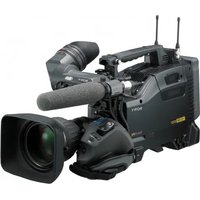
- OWNER'S RECORD
- WARNING
- SYMBOL ON THE PRODUCTS
- FOR THE CUSTOMERS IN THE U.S.A
- WARNING ON POWER CONNECTION
- WARNING ON POWER CONNECTION FOR MEDICAL USE
- FOR THE CUSTOMERS IN THE U.S.A. AND CANADA
- FOR THE CUSTOMERS IN CANADA (FOR DXC-C33)
- FOR THE CUSTOMERS IN EUROPE (FOR DXC-C33P)
- IMPORTANT SAFEGUARDS/NOTICE FOR USE IN THE MEDICAL ENVIRONMENTS
- CAUTION
- IMPORTANT EMC NOTICES FOR USE IN MEDICAL ENVIRONMENTS
- TABLE OF CONTENTS
- OVERVIEW
- ADJUSTING AND SETTING WITH MENUS
- OPERATION
- INSTALLATION AND CONNECTIONS
- APPENDIX
- FEATURES
- HIGH-QUALITY IMAGES
- PRECISE PICTURE CONTROL FUNCTIONS BY THE ADOPTION OF LSI DIGITAL SIGNAL PROCESSING TECHNOLOGY
- COMPACT AND LIGHTWEIGHT REMOTE CAMERA HEAD SYSTEM
- I.LINK (DV) DIGITAL INTERFACE EQUIPPED
- FREEZE AND LONG TERM EXPOSURE FUNCTIONS
- RS-232C INTERFACE
- LOCATION AND FUNCTIONS OF PARTS AND CONTROLS
- CAMERA HEAD
- LENS MOUNT
- NOTE
- CAMERA CABLE CONNECTOR (20-PIN)
- ③ SCREW HOLES
- CAMERA CONTROL UNIT
- ① (POWER) SWITCH AND INDICATOR
- ② FREEZE BUTTON AND INDICATOR
- ③ ←/FILE SELECT BUTTON
- WHILE THE MENU IS DISPLAYED
- ④↑/BLACK (BLACK BALANCE) BUTTON
- ⑤→/ WHITE (WHITE BALANCE) BUTTON
- ⑥MENU BUTTON
- ⑦ ENTER BUTTON
- ⑧ AE AREA SELECT BUTTON
- ⑨ LOCK BUTTON AND INDICATOR
- AE LEVEL CONTROL
- ⑪ GAIN RED/BLUE CONTROLS
- GAIN CONTROL
- ↓ BUTTON
- ⑭BARS (COLOR BARS OUTPUT) BUTTON
- ⑮CAMERA CONNECTOR (20-PIN)
- VIDEO OUTPUT CONNECTOR (BNC TYPE)
- ⑰ I* DV CONNECTOR (6-PIN)
- FS/TRIG IN (FOOT SWITCH/TRIGGER INPUT) CONNECTOR (STEREO MINIJACK)
- EXT SYNC (EXTERNAL SYNC) (HD, VD/SYNC) CONNECTORS (BNC TYPE)
- ⑳ EQUIPOTENTIAL GROUND TERMINAL
- AC IN SOCKET
- REMOTE CONNECTOR (MINI DIN 8-PIN)
- RGB/SYNC CONNECTOR (D-SUB 9-PIN)
- S·VIDEO OUTPUT CONNECTOR (MINI DIN 4-PIN)
- ABOUT ON-SCREEN MENUS
- ① CURSOR
- ②SETTING MENU ITEMS
- ③REMOTE CONTROL UNIT INDICATOR
- ④USER PRESET FILE
- ⑤OPERATIONAL MESSAGE
- ①SETTING MENU
- ② SETTING ITEMS
- ③ SET VALUES
- OPERATION THROUGH MENUS
- TO RESET TO THE INITIAL SET VALUE
- TO RETURN TO THE NORMAL SCREEN
- ADJUSTING THE SETTING ITEMS WITH THE CONTROLS ON THE FRONT OF THE CAMERA CONTROL UNIT
- EXPOSURE MENU
- GAIN
- STEP
- AGC
- LIMIT
- HYPER
- SHUTTER
- OFF
- SPEED
- TO SET THE SHUTTER SPEED
- VARIABLE
- TO CONVERT THE VALUE INTO THE SHUTTER SPEED
- LONG-EXPOSURE MODE
- CLEAR SCAN MODE
- CCD-IRIS
- KNOB
- AE SETUP
- AE LEVEL
- AE AREA1/AE AREA
- LARGE, MID, SPOT AND SLIT
- AE SPEED
- AE DETECT
- CONTRAST MENU
- EFFECT
- MANUAL
- KNEE POINT
- BLACK STRETCH
- DCC+ (DYNAMIC CONTRAST CONTROL +)
- DYNALATITUDE
- GAMMA
- ON
- LEVEL
- MASTER PEDESTAL
- (RED) PEDESTAL, B. (BLUE) PEDESTAL
- WHITE BALANCE MENU
- MODE
- (RED) PAINT, B. (BLUE) PAINT
- AREA
- ATW NORMAL/ATW WIDE
- PAINT, B. PAINT
- GAIN, B. GAIN
- K
- ENHANCER MENU
- DETAIL
- ALL
- FREQUENCY
- TARGET
- LINEAR MATRIX
- TARGET COLOR
- IN
- RANGE
- TO SPECIFY A COLOR
- OUT
- GENERAL MENU
- CCD MODE
- FIELD
- FRAME
- SHADING COMP. (SHADING COMPENSATION)
- FS/TRIG IN (FOOT SWITCH/TARGET INPUT)
- FS
- TRIGGER
- POLARITY
- NEGA
- FLICKER CANCELLER
- SYSTEM MENU
- BAUD RATE
- D-SUB VIDEO
- D-SUB SYNC
- SYNC
- WEN-ODD/WEN-EVEN/WEN-NORM
- RGB SYNC
- G
- RGB
- EXT SYNC
- PHASE
- SC. PHASE ROUGH
- SC. PHASE FINE
- SIGNAL
- SCENE FILE MENU
- FILE SELECT
- LOAD
- TO STORE THE SETTING
- SHOOTING
- BASIC SHOOTING PROCEDURE
- ADJUSTING THE BLACK BALANCE
- BLACK BALANCE ADJUSTMENT ERRORS
- ADJUSTING THE WHITE BALANCE
- NOTES
- WHITE BALANCE ADJUSTMENT ERRORS
- ADJUSTING THE PICTURE TONE IN A MULTI-CAMERA SYSTEM
- CONNECTING THE CAMERAS TO VIDEO EQUIPMENT WITH PHASE INDICATION CAPABILITY
- CONNECTING THE CAMERAS TO VIDEO EQUIPMENT WITHOUT PHASE INDICATION CAPABILITY
- INSTALLATION
- APPLICABLE LENS
- MOUNTING THE LENS
- MOUNTING A MICROSCOPE ADAPTOR
- MOUNTING ON A TRIPOD
- TO ATTACH THE SUPPLIED TRIPOD ADAPTOR
- ATTACHING TO A WALL OR CEILING
- CONNECTIONS
- CONNECTING BETWEEN THE CAMERA HEAD AND CAMERA CONTROL UNIT
- TO CONNECT THE CAMERA CABLE TO THE CAMERA HEAD
- TO CONNECT THE CAMERA CABLE TO THE CAMERA CONTROL UNIT
- NOTES ON CONNECTION BETWEEN THE CAMERA HEAD AND CAMERA CONTROL UNIT
- CONNECTING THE AC POWER CORD
- CONNECTING TO VIDEO EQUIPMENT WITH COMPOSITE VIDEO INPUT CONNECTORS
- CONNECTING TO VIDEO EQUIPMENT WITH S-VIDEO INPUT CONNECTOR
- CONNECTING TO VIDEO EQUIPMENT WITH RGB INPUTS
- CONNECTING TO VIDEO EQUIPMENT WITH DV INPUT CONNECTOR
- CONNECTING TWO OR MORE CAMERAS — MULTI-CAMERA SYSTEM
- CONNECTING TO A REMOTE CONTROL UNIT
- OPERATING THE CAMERA WITH THE RM-C950 REMOTE CONTROL UNIT
- CONNECTING TO A COMPUTER
- CONNECTIONS FOR SHOOTING USING A FLASH
- CONNECTIONS FOR DISPLAYING A FREEZE PICTURE USING A FOOT SWITCH
- PRECAUTIONS
- OPERATING OR STORAGE LOCATION
- VENTILATION
- TRANSPORTATION
- CLEANING
- TYPICAL CCD PHENOMENA
- VERTICAL SMEAR
- ALIASING
- BLEMISHES
- WHITE SPECKLES
- LIST OF MESSAGES
- WEN PULSE TIMING CHART
- SPECIFICATIONS
- IMAGE SYSTEM/OPTICAL SYSTEM
- VIDEO SYSTEM
- FUNCTIONS/PERFORMANCE
- INPUTS/OUTPUTS
- MEDICAL SPECIFICATIONS
- OPTIONAL ACCESSORIES
- LENSES
- REMOTE CONTROL UNIT
- MICROSCOPE ADAPTOR
- CAMERA CABLE
- D-SUB CONNECTOR CABLE
- DIMENSIONS — CAMERA HEAD
- DIMENSIONS — CAMERA CONTROL UNIT
- MENU CONFIGURATION
- INSTALLATION AND CONNECTION
- GENERAL
- ① LENS MOUNT
Brand : SONY
Model : DXC-C33P
Category : Camcorder