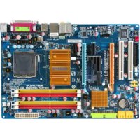
GA-A55-S3P - Motherboard GIGABYTE - Free user manual and instructions
Find the device manual for free GA-A55-S3P GIGABYTE in PDF.
Download the instructions for your Motherboard in PDF format for free! Find your manual GA-A55-S3P - GIGABYTE and take your electronic device back in hand. On this page are published all the documents necessary for the use of your device. GA-A55-S3P by GIGABYTE.
USER MANUAL GA-A55-S3P GIGABYTE
GA-A55-S3P User's Manual Rev. 1001 12ME-A55S3P-1001R
Declaration of Conformity
DECLARATION OF CONFORMITY
Densson Responsible Party Name:G.B.T. INC. (U.S.A.) Address: 17358 Railroad Street City of Industry, CA 91748 Phone/Fax No: (818) 854-9338/ (818) 854-9339 hereby declares that the product Resa comm ag a DEN 800822 Generic mari standard Pat 2 Produet Name: Motherboard Model Number: GA-A55-S3P oensess Dons mm runs nero Conforms to the following specifications: FCC Part 15, Subpart B, Section 15.107(a) and Section 15.109 (a).Class B Digital Device Supplementary Information: This device complies with part 15 ofthe FCC Rules. Operation is subjeet to the following two conditions: (1) This device may not cause harmful and (2) this device must accept any inference received, including that may cause undesired operation. Representative Person's Name: ERIC LU Signature: Eric DENON Say has ane DEMO Cana ant Sat EEE nb po jrs UPS Sara. um Faang ane Timmy Huang {Saro)
Copyright © 2011 GIGA-BYTE TECHNOLOGY CO. LTD. Al rights reserved The trademarks mentioned in this manual are legally registered to their respective owners. Disclaimer Information in this manual is protected by copyright laws and is the property of GIGABYTE. Changes to the specifications and features in this manual may be made by GIGABYTE with- out prior notice. No part of this manual may be reproduced, copied, translate, transmitted, or published in any form or by any means without GIGABYTE's prior written permission. Mn order to assist in the use of this product, carefully read the User's Manual. m For product-related information, check on our website at: http://www.gigabyte.com Identifying Your Motherboard Revision The revision number on your motherboard looks like this: "REV: X.X." For example, "REV: 1.0" means the revision of the motherboard is 1.0. Check your motherboard revision before updating motherboard BIOS, drivers, or when looking for technical information. Example:
Chapter 1 Hardware Installation
Chapter 2 BIOS Setup.
2-5 2-6 2-8 2-10 2-41 2-12 2-13
Box Contents F1 GA-A55-S3P motherboard F1 Motherboard driver disk F1 Two SATA cables F1 Users Manual F1 1/0 Shield The box contents above are for reference only and the actual items shall depend on the product package you obtain.
DDR3 1866/1600/1333/1066 MHz = | Dual Channel Memory HDMI UMI
Line Out (Front Speaker Out)—| Line In (Rear Speaker Out)— MIC (Center/Subwoofer Speaker Out)— S/PDIF Out PS/2 KB/Mouse
pter 1 Hardware Installat 141 Installation Precautions The motherboard contains numerous delicate electronic circuits and components which can become damaged as a result of electrostatic discharge (ESD). Prior to installation, carefully read the user's manual and follow these procedures: + Prior to installation, do not remove or break motherboard S/N (Serial Number) sticker or warranty sticker provided by your dealer. These stickers are required for warranty validation. Always remove the AC power by unplugging the power cord from the power outlet before installing or removing the motherboard or other hardware components. When connecting hardware components to the internal connectors on the motherboard, make sure they are connected tightly and securely. When handling the motherboard, avoid touching any metal leads or connectors. Itis best to wear an electrostatic discharge (ESD) wrist strap when handling electronic com- ponents such as a motherboard, APU or memory. If you do not have an ESD wrist strap, keep your hands dry and first touch a metal object to eliminate static electricity. Prior to installing the motherboard, please have it on top of an antistatic pad or within an electrostatic shielding container. Before unplugging the power supply cable from the motherboard, make sure the power sup- ply has been turned off. Before turning on the power, make sure the power supply voltage has been set according to the local voltage standard. Before using the product, please verify that all cables and power connectors of your hard- ware components are connected. To prevent damage to the motherboard, do not allow screws to come in contact with the motherboard circuit or its components. Make sure there are no leftover screws or metal components placed on the motherboard or Within the computer casing. Do not place the computer system on an uneven surface. Do not place the computer system in a high-temperature environment. Turning on the computer power during the installation process can lead to damage to sys- tem components as well as physical harm to the user. If you are uncertain about any installation steps or have a problem related to the use of the product, please consult a certified computer technician.
1-2 Product Specifications es APU FM1 Socket: - AMD Aseries processors/AMD E2 series processors (Go to GIGABYTE's website for the latest APU support list.) © Chipset
Lo Menoy 2x1.5V DDR3 DIMM sockets supporting up to 16 GB of system memory Due to Windows 32-bitoperating system limitation, when more than 4 GB of physical memory is installed, the actual memory size displayed vil be less than 4 GB. Dual channel memory architecture Support for DDR3 1866/1600/1333/1066 MHz memory modules (Go to GIGABYTE's website for the latest supported memory speeds and memory modules.) @ Onboard Graphics APU: = 1x HDMI por, supporing a maximum resolution of 1920x1200 (HDMI port do not support Hot plug. If you want to change to another graphics: port when the computer is on, be sure to turn off the computer first.) (©) Audio Realtek ALC887 codec High Definition Audio 2/4/5.1/7.1-channel
- To configure 7.1-channel audio, you have Lo use an HD front panel audio module and enable the muli-channel audio feature through the aucio driver. Support for S/PDIF Out Eg]LAN + 1 x Realtek RTL8111E chip (10/10/1000 Mbit) D ©rarson Shi + TX PCI Express x16 io ruming atx18 + 4x PCI Express x slots (Al PCI Express slots conform to the PCI Express 2.0 standard.) +_2xPCIslots CA Mult-Graphics + Support for AMD Dual Graphics technology HI Technology *_Only A series APUs support AMD Dual Graphics. A S'urece Itrice Chipset: = 6x SATA 3Gb/s connectors supporting up to 6 SATA 3Gb/s devices = Support for RAID 0, RAID 1, RAID 10, and JBOD & USB Chipset: = Upto 12 USB 2.0/1. ports (6 ports on the back panel, 6 ports available through the intemal USB headers) x 24-pin ATX main power connector 1 x4-pin ATX 12V power connector 6 x SATA 3Gb/s connectors 1 XAPU fan header 1 x system fan header 1 x power fan header 1 x front panel header 1 x front panel audio header 1 x SIPDIF Out header
Intemal 3xXUSB 20/1 headers Connectors 1 x clearing CMOS jumper 1 x Trusted Platform Module (TPM) header CRE 1 x PSI2 Keyboard port Connectors 1 xPS/2 mouse port 1 x serial port 1 x HDMI port 6x USB 2.0/1.1 ports 1 XRJ-45 port 3 x audio jacks (Line In/Line Out/Microphone) 1@) 10 controler iTE IT8720 chip E Hardware Monitor System voltage detection APUISystem temperature detection APUISystem/Power fan speed detection APU overheating waming APUISystem/Power fan fail warning APUI/System fan speed control *_Whetherthe APU/system fan speed control function is supported will depend on the APU/system cooler you instal. ÉLS 2x32 Mbit flash Use oflicensed AWARD BIOS Support for DualBlOS" PnP 1.02, DMI 2.0, SM BIOS 2.4, ACPI 1.0b fig Uriue Feaures + Support or @BIOS Support for Q-Flash Support for Xpress BIOS Rescue Support for Download Center Support for Xpress Install Support for Xpress Recovery2 Support for EasyTune *_ Available functions in EasyTune may differ by motherboard model Support for Smart Recovery Support for Auto Green Support for ON/OFF Charge Support for 3TB+ Unlock Support for Q-Share @ Bundled
Software Norton Internet Security (OEM version) Re Operating (7 System Support for Microsoft® Windows 7/Vista/XP Form Factor ATX Form Factor; 30.5cm x 19.0cm
- GIGABYTE reserves the right to make any changes lo the product specifications and product-related information without prior notice.
Installing the APU Read the following guidelines before you begin to install the APU Make sure that the motherboard supports the APU (Go to GIGABYTE's website for the latest APU support ist.) Aays tum of the computer and unplug the power cord from the power outlet before installing the APU to prevent hardware damage Locate the pin one of the APU. The APU cannot be inserted if oriented incorrect. Apply an even and thin layer of thermal grease on the surface of the APU. Do not turn on the computer if the APU cooler is not installed, otherwise overheating and dam- age ofthe APU may occur. Set the APU host frequency in accordance with the APU speciications. I is not recommended that the system bus frequency be set beyond hardware specifications since it does not meet the standard requirements for the peripherals. If you wish to set the frequency beyond the standard speciications, please do so according to your hardware specifcations including the APU, graph- ics card, memory, hard drive, etc. Installing the APU A. Locate the pin one (denoted by a small triangle) of the APU socket and the APU. A Small angle Mark Denoles Pin One of the FMt Socket Socket ETES A Smal| Tiangle Maring Denotes APU Pin One APU
1-4 Installing the Memory Read the following guidelines before you begin to install the memory: À + Make sure that the motherboard supports the memory. It is recommended that memory of the same capacity, brand, speed, and chips be used. (Go to GIGABYTE's website for the latest supported memory speeds and memory modules.) + Always tu off the computer and unplug the power cord from the power outlet before installing the memory to prevent hardware damage. + Memory modules have à foolproof design. À memory module can be installed in only one direc- tion. If you are unable to insert the memory, switch the direction. Dual Channel Memory Configuration This motherboard provides two DDR3 memory sockets and supports Dual Channel Technology. After the memory is installed, the BIOS will automatically detect the specifications and capacity of the memory. En- abling Dual Channel memory mode will double the original memory bandwidth. The two DDR3 memory sockets are divided into two channels and each channel has one memory socket as following: » Channel 0: DDR3_2 » Channel 1: DDR3_1 Due to APU limitations, read the following guidelines before installing the memory in Dual Channel mode. 1... Dual Channel mode cannot be enabled if only one DDR3 memory module is installed 2... When enabling Dual Channel mode with to memory modules, it is recommended that memory of the same capacity, brand, speed, and chips be used for optimum performance 1-5 Installing an Expansion Card Make sure the motherboard supports the expansion card. Carelull read the manual that came with your expansion card. + Always tu off the computer and unplug the power cord from the power outlet before installing an expansion card to prevent hardware damage. î Read the following guidelines before you begin to instal an expansion card
1-6 Setup of the AMD Dual Graphics Configuration Combining the onboard GPU with a discrete graphics card, AMD's Dual Graphics technology can provide significantly advanced display performance for AMD platform. Read the following instructions on configuring à Dual Graphics system A. System Requirements - AMD À series processor - Windows 7 operating system - An AMD Dual Graphics technology-supported motherboard and correct driver - An AMD Radeon HD 6000 series graphics card that supports AMD Dual Graphics technology (for more details, please visit AMD's official website) and correct driver B. Installing the Graphics Cards and Configuring BIOS Setup Step 1 Observe the steps in "1-5 Installing an Expansion Card” and install an AMD Dual Graphics technology- supported graphics card on the PCIEX16 slot, Plug the monitor cable into the graphics card and start up your computer. Step 2 Enter BIOS Setup to set he following items under {he Advanced BIOS Features menu - Set UMA Frame Buffer Size to 512MB or 1024MB. - Set Init Display First to Onboard. Save the settings and exit BIOS Setup. Power off your computer. Step 3 Remove the monitor cable from the graphics card and plug it into the integrated graphics port on the back panel and restart your computer. C. Configuring the Graphics Driver After installing the graphics card driver in the operating system, go to EEE the AMD VISION Engine Control Center. Browse to Performance\ AMD CrossFire" and ensure the Enable CrossFire” check box is : selected. (Note) Make sure the drivers for the Chipset, onboard graphics, and external graphics card are properiy installed. = 12-
1-7 Back Panel Connectors le se) © e PS/2 Keyboard and PS/2 Mouse Port Use the upper port (green) to connect a PS/2 mouse and the lower port (purple) to connect a PSI2 key- board © Serial Port Use the serial port to connect devices such as a mouse, modem or other peripherals. © HDMI Port(") HDMI (High-Definition Multimedia Interface) is an all-digital audio/video interface capable of transmit- ‘ing uncompressed audio/video signals. The HDMI port is HDCP compliant and supports Dolby TrueHD and DTS HD Master Audio formats. It also supports up to 192KHz/24bit 8-channel LPCM audio output. You can use this port to connect your HDMI-supported monitor. The maximum supported resolution is 1920x1200, but the actual resolutions supported are dependent on the monitor being used. After installing the HDMI monitor, make sure to set the default sound playback device to HDMI. (The item name may differ depending on your operating system. The screenshot below is from Windows 7.) Cm = | In Windows 7, select Start>Control Panel>Hardware and Sound>Sound>Playback, set Realtek HDMI Output - ATI HDMI Audio to the default playback device. In order to get better playback quality, when playing the HD DVD or Blu-ray discs, refer to the recom- mended system requirements (or better) below. + Processor: AMD À series/AMD E2 series APU + Memory: Tivo 1 GB DDR3 1333 memory modules with dual channel mode enabled + BIOS Setup: Atleast 512 MB of UMA Frame Bufer Size (refer to Chapter 2, "BIOS Setup" "Advanced BIOS Features," for more information) + Playback software: CyberLink PowerDVD 10.0 or later (Note: Please ensure Hardware Acceleration is enabled. Whether Hardware Acceleration can be enabled for 3D Blu-ray discs is dependent on the APU being used.) + HDCP compliant monitor(s) Note) HDMI port do not support Hot plug. I you want to change to another graphics port when the com- puter is on, be sure to turn off the computer first. -T3-
© USB 2.0/1.1 Port The USB port supports the USB 2.0/1.1 speciication. Use this port for USB devices such as à USB key- board/mouse, USB printer, USB flash drive and etc. © RJ-45 LAN Port The Gigabit Ethemet LAN port provides Internet connection at up to 1 Gbps data rate. The following describes the states of he LAN port LEDS. Connection! SpediED AcWYLED Connecton/Speed LED: Aciviy LED: SRE | Descipion SU] Description ul range | 1 Gops ais rate Binking | Data ransmission or receningis oocuring XELLUIL Green | 100 Mbps deu rate Of | No ai tansmissonorrecengs oœcuring DNS or 10 Mbps data rate @ Line In Jack (Blue) The default line in jack. Use this audio jack for line in devices such as an optical drive, walkman, etc. & Line Out Jack (Green) The default line out jack. Use this audio jack for a headphone or 2-channel speaker. This jack can be used to connect front speakers in a 4/5.1/7.1-channel audio configuration. & Mic In Jack (Pink) The default Mic in jack. Microphones must be connected to this jack. E To configure 7.1-channel audio, you have to use an HD front panel audio module and enable the multi-channel audio feature through the audio driver. device and then remove it from the motherboard. + When removing the cable, pull it straight out from the connector. Do not rock it side to side to prevent an electrical short inside the cable connector. î +. When removing the cable connected to a back panel connector, first remove the cable from your
Read the following guidelines before connecting extemal devices First make sure your devices are compliant with the connectors you wish to connect. + Before installing the devices, be sure to turn off the devices and your computer. Unplug the power cord from the power oulet to prevent damage to the devices + After instaling the device and before tuning on the computer, make sure the device cable has been securely aftached to the connector on the motherboard.
1/2) ATX_12V/ATX (2x2 12V Power Connector and 2x12 Main Power Connector) With the use of the power connector, the power supply can supply enough stable power to all the com- ponents on the motherboard. Before connecting the power connector, first make sure the power supply is tumed off and all devices are proper installed. The power connector possesses a foolproof design. Connect the power supply cable to the power connector in the correct orientation. The 12V power con- nector mainly supplies power to the APU. Ifthe 12V power connector is not connected, the computer il not start. To meet expansion requirements, itis recommended that a power supply that can withstand high power consumption be used (S00W or greater). If a power supply is used that does not provide the required power, the result can lead to an unstable or unbootable system. An ta Jar Pin No. | Definition 1 GND 2 [UC 2 [ew an tav 3 [#2 4 [Ha Ga ax Anal Pin No. | Defniion Pin No. | Defniion ME 3 |[3w 2 |3w 4 [1 3 GND 15 GND DEN 16 | PS-ON (soft On) = 5 [en 17 | env GT Î DE 18 |ceN = 7 _|Gw 19 |[Gn EN 8 | Power Good 20 |-5v 9 | SVSB (sandby #5) RE 0 [1 2 | A1] HV (On 722 pn ADO] 23 | +5V (On for 2xt2:pin ATX) 1 Le 12] 33V(Onÿor2x12pinAD0 | 24] GND [Oniy for 2xt2:pin ATX) ce]
The motherboard has a 4-pin APU fan header (CPU_FAN), a 4-pin (SYS_FAN) system fan header, and à 3-pin power fan header (PWR_ FAN). Most fan headers possess a foolproof insertion design. When connecting a fan cable, be sure to connect it in the correct orientation (the black connector wire is the ground wire). The motherboard supports APU fan speed control, which requires the use of a APU fan with fan speed control design. For optimum heat dissipation, it is recommended that a system fan be installed inside the chassis. CPU FAN: Pin No. | Definition 1 GND 2 | H2VISpeed Control CPU FAN 3 | Sense
Speed Control SYS FAN Pin No. | Definition GND 12V ISpeed Control Sense Reserve Pin No. | Definition ï T_| Gen PAR FAN 2 [a 3 | Sense + Be sure Lo connect fan cables to the fan headers to prevent your APU and system from overhealing. Over- heating may result in damage to the APU or the system may hang + _ These fan headers are not configuration jumper blocks. Do not place a jumper cap on the headers. SYS FAN CLR_CMOS (Clearing CMOS Jumper) Use this jumper to clear the CMOS values {e.g. date information and BIOS configurations) and reset the CMOS values to factory defaults. To clear the CMOS values, place a jumper cap on the to pins to temporarly short the two pins or use a metal object Ike a screwdriver to touch the to pins for à few seconds. D. pm. D" ess b @D Open: Normal
ue LE = a) values. After clearing the CMOS values and before tuming on your computer, be sure lo remove the jumper cap from the jumper. Failure to do so may cause damage to the motherboard. After syslem restar, go to BIOS Setup to load factory default (select Load Oplimized Default or manually configure the BIOS settings (refer to Chapter 2, "BIOS Setup" for BIOS configurations) î Always tu Of your computer and uplug the power cord from the power ouet before clearing the CMOS -T7-
The SATA connectors conform to SATA 3Gb/s standard and are compatible with SATA 1.5Gb/s standard. Each SATA connector supports a single SATA device. The AMD A75/A55 Chipset supports RAID 0, RAID 1, RAID 10, and JBOD. Refer to Chapter 5, "Confguring SATA Hard Drive(s)," for instructions on configuring a RAID array. Pin No. | Definition GND TXP TXN GND RXN RXP GND î 7 SATA2 0 7] 1] ]sara2 3 SATA2 1 1 | 1 sara? 4 drives. lfmore than two hard drives are to be used, the total number of hard drives must be an even number. + ARAID 10 configuration requires four hard drives. 7 A RAID 0 or RAID 1 configuration requires at least two hard Please connect the L-shaped end of the SATA cable to your SATA hard drive.
BAT (Battery) The battery provides power to keep the values (such as BIOS configurations, date, and time information) in the CMOS when the computer is turned off. Replace the battery when the battery voltage drops to a low level, or the CMOS values may not be accurate or may be lost. mi) "mp You may clear he CMOS values by removing the battery Turn off your computer and unplug the power cord. Gent remove the battery from the battery holder and wait for one minute. (Or use à metal object ike a screwdriver to touch the positive and negative terminals of the battery holder, making them short for 5 seconds.) Replace the battery. Plug in the power cord and restart your computer. Always tum off your computer and unplug the power cord before replacing the battery. Replace the battery with an equivalent one. Danger of explosion if the battery is replaced with an incorrect model. Contactthe place of purchase or local dealer i you are not able to replace the battery by yourself or uncertain about the battery model. When instaling the battery, note the orientation of the positive side (+) and the negative side (-) ofthe battery [ihe positive side should face up). + Used batteries must be handled in accordance with local environmental regulations.
Connect the power switch, reset switch, speaker, chassis intrusion switch/sensor and system status indicator on the chassis to this header according to the pin assignments below. Note the positive and negative pins before connecting the cables MESSSEEPOnEN] [FOer Sep LED [sh Far DRe ct LD | + MSG/PWR (Message/Power/Sleep LED, Yellow/Purple): System Staus [LED | Connects to the power status indicator on the chassis front panel. The LED E] On |is on when the system is operating. The LED is off when the system is in SISHSS [OM | S3/4 sieep state or powered of (85). + PW (Power Suitch, Red) Connect to the power switch on the chassis front panel. You may configure the way to tu off your system using the power switch (refer to Chapter 2, "BIOS Setup." "Power Management Setup." for more information). + SPEAK (Speaker, Orange): Connects to the speaker on the chassis front panel. The system reports system startup status by is- suing a beep code. One single short beep wil be heard if no problem is detected at system startup. If à problem is detected, the BIOS may issue beeps in different patterns Lo indicate the problem. Refer to Chapter 5, "Troubleshooting/" for information about beep codes + HD (Hard Drive Activity LED, Blue) Connects to the hard drive activity LED on the chassis front panel. The LED is on when the hard drive is reading or writing data. + RES (Reset Suitch, Green) Connects to the reset switch on the chassis front panel. Press the reset switch to restart the computer ifthe computer freezes and fals to perform a normal restart. + CI (Chassis Intrusion Header, Gray): Connect to the chassis intrusion switch/sensor on {he chassis that can detect if he chassis cover has been removed. This function requires a chassis with a chassis intrusion switch/sensor. The front panel design may differ by chassis. À front panel module mainly consists of power Bien reset switch, power LED, hard drive activity LED, speaker and etc. When connecting your chassis front panel module to this header, make sure the wire assignments and the pin assign- ments are matched correctiy.
The front panel audio header supports Intel High Definition audio (HD) and AC'97 audio. You may connect your chassis front panel audio module to this header. Make sure the wire assignments of the module con- nector match the pin assignments of the motherboard header. Incorrect connection between the module connector and the motherboard header will make the device unable to work or even damage it. =) For HD Front Panel Audio: For AC'97 Front Panel Audio: [ 5 8.1.2 Pin No. | Defnition Pin No. | Definition [ni 1 MIC2 L {1 MIC n C1 2 |eN 2 [ew (=! 3 | MCZR 3 | MCPower (=) Î 4 |-ACZDET 4 [Nc D 5 [UNER 5 |ineouf) D 6 |eN 6 [Nc = ] T_| AUDIO D 7 [Nc == 8 |NoPn 8 |NoPin == 9 [UNE 9 |ünout) En) 10 [en 10 [Nc The front panel audio header supports HD audio by default. If your chassis provides an AC'97 front panel audio module, refer to the instructions on how to activate AC'97 functionality via the audio software in Chapter 5, "Configuring 2/4/5.1/7.1-Channel Audio." Audio signals will be present on both of the front and back panel audio connections simultane- ousiy. If you want to mute the back panel audio (only supported when using an HD front panel audio module), refer to Chapter 5, "Configuring 2/4/5.1/7.1-Channel Audio." Some chassis provide à front panel audio module that has separated connectors on each wire instead of a single plug. For information about connecting the front panel audio module that has different wire assignments, please contact the chassis manufacturer.
This header supports digital S/PDIF Out and comnects a S/PDIF digital audio cable (provided by expan- sion cards) for digital audio output from your motherboard to certain expansion cards like graphics cards and sound cards. For example, some graphics cards may require you to use a S/PDIF digital audio cable for digital audio output from your motherboard to your graphics card if you wish to connect an HDMI display to the graphics card and have digital audio output from the HDMI display at the same time. For information about connecting the SIPDIF digital audio cable, carefully read the manual for your expan- sion card. Pin No. | Definition 8 1 | SPDIFO ! 2 |GND
cord from the power outlet to prevent damage to the USB bracket
43) TPM (Trusted Platform Module Header)
You may connect a TPM (Trusted Platform Module) to this header.
apter2 BIOS Setup To access he BIOS Setup program, press the <Delete> key during the POST when the pour is turned on. To see more advanced BIOS Setup menu options, you can press <Ctri> + <F> in the main menu of the BIOS Setup program. To upgrade the BIOS, use either the GIGABYTE Q-Flash or @BIOS utility. + Q-Flash allows the user to quickly and easily upgrade or back up BIOS without entering the operating system. + @BIOS is a Windows-based utility that searches and downloads the latest version of BIOS from the Internet and updates the BIOS. version of BIOS, it is recommended that you not flash the BIOS. To flash the BIOS, do it with caution. Inadequate BIOS flashing may result in system malfunction. ILis recommended that you not alter the default settings (unless you need to) to prevent system instabilty or other unexpected results. Inadequately altering the settings may result in system's failure to boot. IFthis occurs, try to clear the CMOS values and reset the board to default values (Refer to the "Load Optimized Default" section in this chapter or introductions of the battery! clearing CMOS jumper in Chapter 1 for how to clear the CMOS values.) + Because BIOS flashing is potentally risk, if you do not encounter problems using the current 2-1 Startup Screen The following screens may appear when the computer boots. A. The LOGO Screen (Default): GIGABYTE Ultra Durable"" series Motherboard Casse eme f function keys B. The POST Screen Motherboard Model BIOS Version. Function Keys
2-2 The Main Menu Once you enter the BIOS Setup program, the Main Menu (as shown below) appears on the screen. Use ar- row keys to move among the items and press <Enter> to accept or enter a sub-menu. (Sample BIOS Version: F1c) CMOS Setup Utility-Copyright (C) 1984-2011 Award Software Load Optim Set Supervisor access more advanced options. When the system is not stable as usual, select the Load Optimized Defaults item to set your system to its defaults. The BIOS Setup menus described in this chapter are for reference only and may difer by BIOS version à +_ If you do not find the settings you want in the Main Menu or à submenu, press <Ctrl>+<F{> to m The Functions of the <F11> and <F12> keys (For the Main Menu Only) + F11: Save CMOS to BIOS This function allows you to save the current BIOS settings to a profile. You can create up to 8 profiles (Profile 1-8) and name each profil. First enter the profile name (to erase the default profile name, use the SPACE key) and then press <Enter> to complete. + F12: Load CMOS from BIOS If your system becomes unstable and you have loaded the BIOS default settings, you can use this function to load the BIOS settings from a profile created before, without the hassles of reconfiguring the BIOS settings. First select the profile you wish to load, then press <Enter> to complete.
PCIe Spread Spectrum Disabled] Set Memory Clock [Auto] Ciock DRAM Configuration {Press Enter] [Auto] Whether the system wi work stably with the overclock/overvolage settings you made is depen- dent on your overall system configurations. Incorreclly doing overclocklovervoltage may result in damage to CPU, chipset, or memory and reduce the useful ife of these components. This page is for advanced users only and we recommend you not to alter the default settings to prevent system instabilty or other unexpected result. (Inadequately altering the settings may result in systems failure to boot. Ifthis occurs, clear the CMOS values and reset the board to default values.) When the System Voltage Optimized item blinks in red, it is recommended that you set the System Voltage Control item to Auto to optimize the system voltage settings. IGX Configuration UMA Frame Buffer Size Lauto] Ten Hop VGA Core Clock control [Auto] Tine:Moe Enr Si PUIPD: Value F0: Save SC:Ext F1: General Help S: Previous Values F6: Fail-Safe Defaults Optimized Defaults UMA Frame Buffer Size Frame buffer size is the total amount of system memory allocated solely for the onboard graphics con- troller. MS-DOS, for example, will use only this memory for display. Options are: Auto (default), 256MB. 512MB, 1024ME. < VGA Core Clock control Allows you to determine whether to manually set the VGA Core clock. (Default: Auto) < VGA Core Clock(MHz) Allows you to manually set the VGA Core clock. The adjustable range is from 300 MHz to 2000 MHz. This item is configurable only if the VGA Core Clock control option is set to Manual. (Note) This item is present only when you install a CPU that supports this feature
< CPU Clock Ratio Allows you to alter the clock ratio for the installed CPU. The adjustable range is dependent on the CPU being installed. CPU NorthBridge Freq. Alows you to alter the frequency of the CPU North Bridge controller. Core Performance Boost" Allows you to determine whether to enable the Core Performance Boost (CPB) technology, a CPU performance-boost technology. (Default: Enabled) - CPB Ratio") Alows you alter the ratio for the CPB. The adjustable range is dependent on the CPU being installed (Default: Auto) CPU Host Clock Control Enables or disables the control of CPU host clock. Auto (default) allows the BIOS to automatically adjust the CPU host frequency. Manual allows the CPU Frequency (MHz) item below to be configurable. Note: If your system fails to boot after overclocking, please wait for 20 seconds to allow for automated System reboot, or clear the CMOS values to reset the board to default values. CPU Frequency(MHz) Alows you to manually set the CPU host frequency. This option is configurable only when CPU Host Clock Control is set to Manual. Important It is highly recommended that the CPU frequency be set in accordance with the CPU specifications. PCle Spread Spectrum Enables or disables PCle Spread Spectrum. (Default: Disabled) Set Memory Clock Determines whether to manually set the memory clock. Auto lets BIOS automatically set the memory clock as required. Manual allows the memory clock control item below to be configurable. (Default: Auto) Memory Clock This option is configurable only when Set Memory Clock is set to Manual. » X5.33 Sets Memory Clock to X5.33. » X6.66 Sets Memory Clock to X6.66. » X8.00 Sets Memory Clock to X8.00. » X9.33 Sets Memory Clock to X9.33. Note) This item is present only when you install a CPU that support this feature.
< Bank Interleaving Enables or disables memory bank interleaving. Enabled allows the system to simultaneously access dif. ferent banks of the memory to increase memory performance and stability. (Default: Enabled) + System Voltage Optimized +++ < System Voltage Control Determines whether to manually set the system voltages. Auto lets the BIOS automatically set the system voltages as required. Manual allows all voltage control items below to be configurable. (Default: Auto) CPU PLL Voltage Control Alows you to set the CPU PLL voltage. » Normal Supplies the CPU PLL voltage as required. (Default) »2.100V-2900V The adjustable range is from 2.100V to 2.900V. Note: Increasing CPU voltage may result in damage to your CPU or reduce the useful if of the CPU. « DDR3 Voltage Control Alows you to set memory voltage. » Normal Supplies the memory voltage as required. (Default) »1025V-2135V The adjustable range is from 1.025V to 2.135V. Note: Increasing memory voltage may result in damage to the memory or reduce the useful life of the memory. <_ DDR VTT Voltage Control Alows you to set the DDR VTT voltage. » Normal Supplies the DDR VTT voltage as required. (Default) »0.515V-1.145V The adjustable range is from 0.515V to 1.145V. Note: Increasing memory voltage may result in damage to the memory or reduce the useful life of the memory. <_ FCH Voltage Control Alows you to set the Chipset voltage. » Normal Supplies the Chipset voltage as required. (Default) » 0.900V - 1.480V The adjustable range is from 0.900V to 1.480V. APU VDDP Voltage Control Allows you to set the APU PCle PLL voltage. » Normal Supplies the APU PCIe PLL voltage as required. (Default) » 1.000V-1.480V The adjustable range is from 1.000V to 1.480V. CPU NB VID Control Alows you to set the CPU North Bridge VID voltage. » Normal Supplies the CPU NB VID voltage as required. (Default) » -0.600V -+0.600V The adjustable range is from -0.600V to +0.600V. - CPU Voltage Control Alows you to set the CPU voltage. » Normal Supplies the CPU voltage as required. (Default) » -0.600V -+0.600V The adjustable range is from -0.600V to +0.600V. < Normal CPU Vcore Displays the normal operating voltage of your CPU
4 Standard CMOS Features ‘CMOS Setup Utility-Copyrigh H-2011 Award Software Standard CMOS Features Jun 29 2011 Ten Hop IDE Cha e [None] IDE Channel 0 Sla [None] IDE Cha Ê [None] IDE Channel 1 Sla [None] IDE Cha e [None] IDE Cha e {None] Halt On [AIL, But Keyboard] Enter FI: General Help Previous Date (mm:dd:yy) Sets the system date. Time (hh:mmiss) Sets the system time. IDE Channel 0, 1 Master/Slave # IDE HDD Auto-Detection Press <Enter> to autodetect the parameters of the SATA device on this channel. » IDE Channel 0, 1 Master/Slave Configure your SATA devices by using one of the two methods below: + Auto Lets the BIOS automatically detect SATA devices during the POST. (Default) + None Ifno SATA devices are used, set this item to None so the system will skip the detection of the device during the POST for faster system startup. » Access Mode Sets the hard drive access mode. Options are: Auto (default), CHS, LBA, Large. = IDE Channel 2, 3 Master » IDE Auto-Detection Press <Enter> to autodetect the parameters of the SATA device on this channel. » Extended IDE Drive Configure your SATA devices by using one of the two methods below: + Auto Lets the BIOS automatically detect SATA devices during the POST. (Default) + None Ifno SATA devices are used, set this item to None so the system will Skip the detection of the device during the POST for faster system startup. » Access Mode Sets the hard drive access mode. Options are: Auto (default), Large. » Capacity Approximate capacity of the currently installed hard drive. Halt On Allows you to determine whether the system will stop for an error during the POST. Options are: "All Errors," "No Errors," "All, But Keyboard”. (Default) 7 Memory These fields are read-only and are determined by the BIOS POST.
‘CMOS Setup Utiliy-Copyright (C) 1984-2011 Award Sofware Advanced BIOS FTOX Configuration Ten Hop AMD C6 Support Virtualization AMD K& Cool&Quict control C-state Pmin Hard Disk Boot Prorit EFI CD/DVD Boot Option: First Boot Device Second Boot Device Third Boot Device Password Check HDDS. Away Mode Full Screen LOGO S Init Display First F7: Optimized Defaul 1GX Configuration The settings in this submenu are synchronous to those under the same items on the MB Intelligent Tweaker(M.LT.) main menu. - AMD C6 Support Allows you to determine whether to let the CPU enter C6 mode in system halt state. When enabled, the CPU core frequency will be reduced during system halt state to decrease power consumption. The C6 state is a more enhanced power-saving state than C1. (Default: Disabled) Virtualization Virualization allows a platform to run multiple operating systems and applications in independent part- tions. With virtualization, one computer system can function as multiple virtual systems. (Default: Disabled) AMD K8 Cool&Quiet control » Auto Lets the AMD Cool'n'Quiet driver dynamically adjust the CPU ciock and VID to re- duce heat output from your computer and its power consumption. (Default) » Disabled Disables this function. - C-state Pmin Allows you to determine wiether to let the CPU enter C1 mode in system halt state. When enabled, the CPU core frequency and voltage will be reduced during system halt state to decrease power con- sumption. Auto lets the BIOS automatically configure this setting. (Default: Auto) - Hard Disk Boot Priority Specifies the sequence of loading the operating system from the installed hard drives. Use the up or down arrow key to select a hard drive, then press the plus key <+> (or <PageUp>) or the minus key <-> (or <PageDoun>) to move it up or dou on the list. Press <Esc> Lo exit this menu when finished <_ EFI CD/DVD Boot Option Set this item to EFI if you want to install the operating system to a hard drive larger than 2.2 TB. Make sure the operating system to be installed supports booting from a GPT partition, such as Windows 7 64- bit and Windows Server 2003 64-bit. Auto lets the BIOS automatically configure this setting depending on the hard drive you install. (Default: Auto) First/Second/Third Boot Device Specifies the boot order from the available devices. Use the up or down arrow key to select a device and press <Enter> to accept. Options are: LS120, Hard Disk, CDROM, ZIP, USB-FDD, USB-ZIP, USB- CDROM, USB-HDD, Legacy LAN, Disabled.
< Password Check Specifies whether a password is required every time the system boots, or only when you enter BIOS Setup. After configuring this item, set the password{s) under the Set Supervisor/User Password item in the BIOS Main Menu. » Setup Apassword is only required for entering the BIOS Setup program. (Default) » System Apassword is required for booting the system and for entering the BIOS Setup program. 7 HDD S.M.ART. Capability Enables or disables the S.MA.R.T. (Self Monitoring and Reporting Technology) capabilty of your hard drive. This feature allows your system to report read/write errors of the hard drive and to issue warnings when a third party hardware monitor utility is installed. (Default: Disabled) < Away Mode Enables or disables Away Mode in Windows XP Media Center operating system. Away Mode allows the system to silentiy perform unattended tasks while in a low-power mode that appears of. (Default: Disabled) Full Screen LOGO Show Alows you to determine whether to display the GIGABYTE Logo at system startup. Disabled displays normal POST message. (Default: Enabled) cr Init Display First Specifies the first initiation of the monitor display from the installed PCI graphics card, PCI Express graphics card, or the onboard graphics. » Onboard Sets the onboard graphics as the first display. » PCI Slot Sets the PCI graphics card on the PCI slot as the first display. » PEG Sets the PCI Express graphics card on the PCIEX16 slot as the first display. (Default) 2-6 Integrated Peripherals 1 Award Sofware OnChip ea Ten Hop OnChip S/ Onboard LAN Function Onboard LAN Boot ROM » SMART LAN Onboard Audio Function Controlle Legacy Function Storage Function Onboard Serial Port Enter Previous OnChip SATA Controller Enables or disables the integrated SATA controllers. (Default: Enabled) OnChip SATA Type (SATA2_0-SATA2_3 connectors) Configures the operating mode of the SATA2_0-SATA2_3 connectors. » Native IDE Allows the SATA controller to operate in Native IDE mode. (Default) Enable Native IDE mode if you wish to install operating systems that support Native mode. » RAID Enables RAID for the SATA controller.
» AHCI Configures the SATA controllers to AHCI mode. Advanced Host Controller Interface (AHCI) is an interface specification that allows the storage driver to enable advanced Serial ATA features such as Native Command Queuing and hot plug. OnChip SATA Port4/5 Type (SATA2_4 and SATA2_5 connectors) This option is configurable only when OnChip SATA Type is set to RAID or AHCI. Configures the oper- ating mode of the SATA2_4 and SATA2_5 connectors. » IDE Disables RAID for the SATA controller and configures the SATA controller to PATA mode. (Default) » As SATA Type | The mode depends on the OnChip SATA Type settings: OnChip SATA Port as ESP CMOS Setup Utiliy-Copyright (C) 1984-2011 Award Sofware OnChip SATA Port as ESP.
Mo Enter Ext Fl: General Help Previous Optimized Def Port0 as ESP/Porti as ESP/Port2 as ESP/Port3 as ESP This option is configurable only when OnChip SATA Type is set to AHCI. Enabled will speed up the hot plug detection of the connected SATA device. (Default: Disabled) Porté as ESP/Port5 as ESP This option is configurable only when OnChip SATA Type is set to AHCI and OnChip SATA Type Port4/5 is set to As SATA Type. Enabled will speed up the hot plug detection of the connected SATA device. (Default: Disabled) < Onboard LAN Function Enables or disables the onboard LAN function. (Default: Enabled) If you wish to install a 3rd party add-in network card instead of using the onboard LAN, set this item to Disabled. Onboard LAN Boot ROM Allows you to decide whether to activate the boot ROM integrated with the onboard LAN chip. (Default: Disabled) < SMART LAN (LAN Cable Diagnostic Function) ‘CMOS Setup Utiliy-Copyright (C) 1984-2011 Award Sofware SMART LAN
Port Ten Hop Open Open Open Open! Length ETS Ext Fl:Genenlk Previous F Optimized Def This motherboard incorporates cable diagnostic feature designed to detect the status of the attached LAN cable. This feature wi detect cabling issue and report the approximate distance to the fault or short.
2-7 Power Management Setup < Onboard Audio Function Enables or disables the onboard audio function. (Default: Enabled) If you wish to install a 3rd party add-in audio card instead of using the onboard audio, set this item to Disabled. USB Controllers Enables or disables the integrated USB controllers. (Default: Enabled) Disabled will turn off all of the USB functionalities below. USB Legacy Function Allows USB keyboard to be used in MS-DOS. (Default: Enabled) USB Storage Function Determines whether to detect USB storage devices, including USB flash drives and USB hard drives during the POST. (Default: Enabled) = Onboard Serial Port Enables or disables the first serial port and speciies its base 1/O address and corresponding interrupt Options are: Auto, 3FB/RQ4 (default), 2FB/IRQ3, 3E8/RQ4, 2E8/RQ3, Disabled 1 Award Sofware Ten Hop USB Wa Modem Rin PME Event HPET Support Power On By Mouse Power On By Keyboard AC Back F jof-Ofr] Power-On b {Disabled] {Disabled] ï Fi: General Help ed Def = Soft-Off by Power button Configures the way to tum off the computer in MS-DOS mode using the power button. » Instant-Off Press the power button and then the system will be turned off instantly. (Default) » Delay 4 Sec. Press and hold the power button for 4 seconds to turn off the system. lfthe power button is pressed for less than 4 seconds, the system will enter suspend mode. USB Wake Up from S3 Allows the system to be awakened from ACPI S3 sleep state by a wake-up signal from the installed USB device. (Default: Enabled) Modem Ring Resume Alows the system to be awakened from an ACPI sleep state by a wake-up signal from a modem that supports wake-up function. (Default: Disabled) Note) Supported on Windows 7IVista operating system only.
< PME Event Wake Up Allows the system to be awakened from an ACPI sleep state by a wake-up signal from a PCI or PCIe de- vice. Note: To use this function, you need an ATX power supply providing at least 1A on the +5VSB lead. (Default: Enabled) HPET Support") Enables or disables High Precision Event Timer (HPET) for Windows 7Vista operating system. (Default: Enabled) Power On By Mouse Allows the system to be tumed on by a PS/2 mouse wake-up event. Note: To use this function, you need an ATX power supply providing at least 1A on the +5VSB lead. » Disabled Disables this function. (Default) » Double Click Double click on left button on the PS/2 mouse to tum on the system. Power On By Keyboard Allows the system to be tumed on by a PS/2 keyboard wake-up event. Note: you need an ATX power supply providing at least 1A on the +5VSB lead. » Disabled Disables this function. (Default) » Password Set a password with 1-5 characters to tu on the system. » Any KEY Press any key on the keyboard to turn on the system. » Keyboard 98 Press POWER button on the Windows 98 keyboard to turn on the system. KB Power ON Password Set the password when Power On by Keyboard is set to Password. Press <Enter> on this item and set a password with up to 5 characters and then press <Enter> to accept. To tum on the system, enter the password and press <Enter>. Note: To cancel the password, press <Enter> on this item. When prompted for the password, press <En- ter> again without entering the password to clear the password settings. 7 AC Back Function Determines the state of the system after the return of power from an AC power loss. » Soft-Off The system stays off upon the retum of the AC power. (Default) » Ful-On The system is tumed on upon he retum of the AC power. » Memory The system retums to it last known awake state upon the return of the AC power. < Power-On by Alarm Determines whether to power on the system at a desired time. (Default: Disabled) If enabled, set the date and time as following: » Date (of Month) Alarm: Turn on the system at a specific time on each day or on a specific day in a month. » Resume Time (hh: mm: ss): Set the time at which the system will be powered on automatically. Note: When using this function, avoid inadequate shutdown from the operating system or removal of the AC power, or the settings may not be effective. ErP Support Determines whether to let the system consume less than 1W power in 5 (shutdown) state. (Default: Disabled) Note: When this item is set to Enabled, the following four functions will become unavailable: PME event wake up, power on by mouse, power on by keyboard, and wake on LAN. Note) Supported on Windows 7IVista operating system only.
‘CMOS Setup Utiliy-Copyright (C) 1984-2011 Award Sofware PC Health Status TDisabled] Ten Hop CPU Warmni CPU FAN Fail Wam SYSTEM FAN Fail Warni POWER FAN Fail Warning Enter FI: General Help Previous Reset Case Open Status Keeps or clears the record of previous chassis intrusion status. Enabled clears the record of previous chassis intrusion status and the Case Opened field will show "No" at next boot. (Default: Disabled) Case Opened Displays the detection status of the chassis intrusion detection device attached to the motherboard CI header. lfthe system chassis cover is removed, this field will show "Yes", otherwise it will show "No". To clear the chassis intrusion status record, set Reset Case Open Status to Enabled, save the settings to the CMOS, and then restart your system. Current Voltage(V) Vcore/DDR3 1.5V/+3.3V/+12V Displays the current system voltages. Current System/CPU Temperature Displays current system/CPU temperature. Current CPU/SYSTEM/POWER FAN Speed (RPM) Displays current CPU/system/power fan speed. CPU Warning Temperature Sets the warning threshold for CPU temperature. When CPU temperature exceeds the threshold BIOS will emit warning sound. Options are: Disabled (default), 60°C/140°F, 70°C/158*F, 80°C/176°F, 90°C/194F. - CPU/SYSTEM/POWER FAN Fail Warning Allows the system to emit warning sound if the CPU/system/power fan is not connected or fails. Check the fan condition or fan connection when this occurs. (Default: Disabled) CPU Smart FAN Control Enables or disables the CPU fan speed control function. Enabled allows the CPU fan to run at different speed according to the CPU temperature. You can adjust the fan speed with EasyTune based on system requirements. lf disabled, the CPU fan runs at full speed. (Default: Enabled)
CPU Smart FAN Mode Specifies how to control CPU fan speed. This item is configurable only if CPU Smart FAN Control is set to Enabled. » Auto Lets the BIOS automatically detect the type of CPU fan installed and sets the optimal CPU fan control mode. (Default) » Voltage Sets Voltage mode for a 3-pin CPU fan. » PWM Sets PWM mode for a 4-pin CPU fan. System Smart FAN Control Enables or disables the system fan speed control function. Enabled allows the system fan to run at dif- ferent speed according to the system temperature. If disabled, system fan runs at full speed. (Default Enabled) 2-9 Load Fail-Safe Defaults CMOS Setup Uüiliy-Copyrigt (C) 1984-2011 Award Sofvare Load Fai-Safe Défauts Load Optimized Defauts Set Supervisor Password Power Man PC Health Press <Enter> on this item and then press the <Y> key to load the safest BIOS default settings. In case system instabilty occurs, you may try to load Fai-Safe defaults, which are the safest and most stable BIOS settings for the motherboard 2-10 Load Optimized Defaults CMOS Setup Utility-Copyright (C) 1984-2011 Award Software Load Fail-Safe Defaults Load Optimized Defaults Set Supervisor Password Power Man PC Health Press <Enter> on this item and then press the <V> key to load the optimal BIOS default settings The BIOS defaults settings help the system to operate in optimum state. Always load the Optimized defaults after updating the BIOS or after clearing the CMOS values.
Load Fail-Safe Defaults Load Optimized Defaults et Supervisor Pas rated Periphé Power Mai PC Health St Press <Enter> on this item and type the password with up to 8 characters and then press <Enter>. You will be requested to confirm {he password. Type the password again and press <Enter>. The BIOS Setup program allows you to specify to separate passwords: <_ Supervisor Password When a system password is set and the Password Check item in Advanced BIOS Features is set to Setup, you must enter the supervisor password for entering BIOS Setup and making BIOS changes When the Password Check item is set to System, you must enter the supervisor password (or user password) at system startup and when entering BIOS Setup < User Password When the Password Check item is set to System, you must enter the supervisor password (or user password) at system startup to continue system boot. In BIOS Setup, you must enter the supervisor password if you wish to make changes to BIOS settings. The user password only allows you to view the BIOS settings but not to make changes To clear the password, press <Enter> on the password item and when requested for {he password, press <Enter> again. The message "PASSWORD DISABLED" will appear, indicating the password has been can- celled. 2-12 Save & Exit Setup CMOS Setup Utility-Copyright (C) 1984-2011 Award Software MB Intelligent T\ Integrated Periphe® DH Power Manageme: Save & Exit Setup ithout Saving Press <Enter> on this item and press the <Y> key. This saves the changes to the CMOS and exits the BIOS Setup program. Press <N> or <Esc> to retum to the BIOS Setup Main Menu.
11 Award Software Standard CMOS Advanced BIOS. Integrated Pe Power Man PC Health 1 BIOS Press <Enter> on this item and press the <Y> key. This exits the BIOS Setup without saving the changes made in BIOS Setup to the CMOS. Press <N> or <Esc> to return to the BIOS Setup Main Menu. apter 3 vers Installatio Before installng the drivers, first install he operating system ES After instaling the operating system, insert the motherboard driver disk into your optical drive. The driver Autorun screen is automatically displayed which looks like that shown in the screen shot below. (If the driver Autorun screen does not appear automatically, go to My Computer, double-click the optical drive and execute the Run.exe program.) After inserting the driver disk, "Xpress Install" will automatically scan your system and then list all the drivers that are recommended to install. You can click the Install AI button and "Xpress Install” will install all the rec- ommended drivers. Or click Install Single Items to manually select the drivers you wish to install. Von se er bon ju rotaonPiane t ss ie)
Configuring SATA Hard Drive(s) Before you begin Please prepare: + At least to SATA hard drives (to ensure optimal performance, it is recommended that you use to hard drives with identical model and capacity). If you do not want to create RAID, you may prepare only one hard drive. + Windows 7/Vista/XP setup disk. + Motherboard driver disk. + AUSB floppy disk drive (needed during Windows XP installation) + An empty formatted floppy disk (needed during Windows XP installation) Configuring the Onboard SATA Controller À. Installing SATA hard drive(s) in your computer Attach one end of the SATA signal cable to the rear of the SATA hard drive and the other end to available SATA port on the motherboard. Then connect the power connector from our power supply to the hard drive. B. Configuring SATA controller mode in BIOS Setup Make sure to configure the SATA controller mode correctly in system BIOS Setup. For the BIOS Setup menus, refer to Chapter 2, "BIOS Setup," "Integrated Peripherals." Steps: Tu on your computer and press <Delete> to enter BIOS Setup during the POST (Power-On Self-Test) Make sure OnChip SATA Controller is enabled. To enable RAID for the SATA2_0/1/2/3 connectors, set OnChip SATA Type to RAID. To enable RAID for the SATA2_4/SATA2_5 connectors, set OnChip SATA Type to RAID and set OnChip SATA Port4/5 Type to As SATA Type Save changes and exit BIOS Setup. œ- BIOS Setup menus described in this section may difler from the exact settings for your moth-
erboard. The actual BIOS Setup menu options you wil| see shall depend on the motherboard you have and the BIOS version C. Configuring RAID set in RAID BIOS Enter the RAID BIOS setup utility to configure a RAID array. After the POST memory test begins and before the operating system boot begins, look for a message which says "Press <Ctrl-F> to enter RAID Option ROM Utility”. Press <Ctri> + <F> to enter the RAID BIOS setup utility. To create a new array, press <2> to enter the LD View/LD Define Menu window. To create an array, press <Ctrl+C> to access the LD Define Menu. In the LD Define Menu, use the up or down arrow key to move to an item for further configu- ration. In the following procedure, we'll create RAID 0 as an example. Steps:
3. Under the Drives Assignments section, press the up or down arrow key to highlight a drive.
4. Press the <SPACE> key or <Y>to change the Assignment option to Y. This action adds the drive to the
disk array. The Drv section will show the number of disks assigned.
Fast Initialization Option has be Figure 2 Then, the message in Figure 8 will appear. Press <Ctri>+<Y> to set the capacity of the RAID array or press other keys to set the array to its maximum capacity. Figure 3
After the creation is complete, the screen wil return to LD View Menu were you will see the newly- created array, Press <Esc> to return to Main Menu and press <Esc> again if you want to exit the RAID BIOS utility.
Making a SATA RAID/AHCI Driver Diskette Before installing Windows XP, connect a USB floppy disk drive to your computer first because you need to in- stall the SATA RAID/AHCI driver from a floppy disk that contains the driver during the OS installation. To copy the RAID/AHCI driver for Windows XP, copy all les in the \BootDr Hxp folder in the motherboard driver disk to your floppy disk. Installing the SATA RAID/AHCI Driver and Operating System À. Installing Windows XP Restart your system to boot from the Windows XP setup disk and press <F6> as soon as you see {he mes- sage "Press F6 if you need to install a 3rd party SCSI or RAID driver" Insert the floppy disk containing the SATA RAID/AHCI driver. Follow the on-screen instructions to install the driver that suits your operating sys- tem. When completed, proceed with the Windows XP installation. B. Installing Windows 7/Vista Restart your system to boot from the Windows 7/Vista setup disk and perform standard OS installation steps. Select Load Driver. Insert the motherboard driver disk and then browse to the location of the driver. Then fol- low the on-screen instructions to load the driver. The locations of the drivers for Windows 7 are as follows: RAID driver for Windows 32-bit: \BootDr\Hw7\RAIDIW7 RAID driver for Windows 64-bit: \BootDrv\Hw7\RAIDIW764A AHCI driver for Windows 32-bit: \BootDr/Hw7\AHCI\W7 AHCI driver for Windows 64-bit: \BootDr/Hw7\AHCI\W764A (Note: The LH/LH64A folder contains the driver for Windows Vista 32-bit/64-bit) After loading the driver, continue the OS installation.