GA-990FXA-UD5 - Motherboard GIGABYTE - Free user manual and instructions
Find the device manual for free GA-990FXA-UD5 GIGABYTE in PDF.
Download the instructions for your Motherboard in PDF format for free! Find your manual GA-990FXA-UD5 - GIGABYTE and take your electronic device back in hand. On this page are published all the documents necessary for the use of your device. GA-990FXA-UD5 by GIGABYTE.
USER MANUAL GA-990FXA-UD5 GIGABYTE
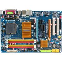
GA-990FXA-UD5 User's Manual Rev. 1001
Declaration of Conformity
DECLARATION OF CONFORMITY
Densson Responsible Party Name:G.B.T. INC. (U.S.A.) Address: 17358 Railroad Street City of Industry, CA 91748 Phone/Fax No: (818) 854-9338/ (818) 854-9339 hereby declares that the product Resa comm ag a DEN 800822 Generic mari standard Pat 2 Produet Name: Motherboard Model Number: GA-990FXA-UDS oensess Dons mm runs nero Conforms to the following specifications: FCC Part 15, Subpart B, Section 15.107(a) and Section 15.109 (a).Class B Digital Device Supplementary Information: This device complies with part 15 ofthe FCC Rules. Operation is subjeet to the following two conditions: (1) This device may not cause harmful and (2) this device must accept any inference received, including that may cause undesired operation. Representative Person's Name: ERIC LU Signature: Eric Lu Date: May 20, 2011 DENON Say has ane DEMO Cana ant Sat EEE nb po jrs UPS Sara. um Faang {Saro) Due May 20.201 none: Timmy Huang
Copyright © 2011 GIGA-BYTE TECHNOLOGY CO. LTD. All rights reserved. The trademarks mentioned in this manual are legally registered to their respective owners. Disclaimer Information in this manual is protected by copyright laws and is the property of GIGABYTE. Changes to the specifications and features in this manual may be made by GIGABYTE with- out prior notice. No part of this manual may be reproduced, copied, translate, transmitted, or published in any form or by any means without GIGABYTE's prior written permission. Documentation Classifications In order to assis in the use of this product, GIGABYTE provides the following types of documentations: m For quick setup of the product, read the Quick Installation Guide included with the product. m For detailed product information, carefully read the Users Manual. For product-related information, check on our website at: http:/\www.gigabyte.com Identifying Your Motherboard Revision The revision number on your motherboard looks like this: "REV: X.X." For example, "REV: 1.0" means the revision of the motherboard is 1.0. Check your motherboard revision before updating motherboard BIOS, drivers, or when looking for technical information. Example:
Chapter 1 Hardware Installation
2-1 Startup Screen 2-2 The Main Menu 2-3 MB Intelligent Tweaker(M. 24 Standard CMOS Features. 2-5 Advanced BIOS Features 2-6 Integrated Peripherals. 2-7 Power Management Setu 2-8 PC Health Status. 29 Load Fail-Safe Defaults. 2-10 Load Optimized Defaults…… 2-11 Set Supervisor/User Password 2-12 Save & Exit Setup. 2-13 Exit Without Saving.
Chapter 3 Drivers Installation...
Box Contents F1 GA-990FXA-UDS5 motherboard F1 Motherboard driver disk M Users Manual 1 Quick Installation Guide EM Four SATA cables 11 1/O Shield #1 One 2-Way SLI bridge connector 5 One 3-Way SLI bridge connector {Note) To enable NVIDIA SLI technology, you need SLI-supported graphics cards, BIOS, and driver. For more details, please go to GIGABYTE's website. +__ The box contents above are for reference only and the actual items shall depend on the product package you obtain. The box contents are subject to change without notice. +__ The molherboard image is for reference only. Optional Items © 2-port USB 2.0 bracket (Part No. 12CR1-1UB030-5'R) E 2-port SATA power cable (Part No. 12CF1-2SERPW-0'R) E COM port cable (Part No. 12CF1-1CM001-3*R) D 2-port IEEE 1394a bracket (Part No. 12CF1-11E008-0*R) D 3.5" Front Panel with 2 USB 3.0/2.0 ports (Part No. 12CR1-FPX582-0'R)
pter 1 Hardware Installat 141 Installation Precautions The motherboard contains numerous delicate electronic circuits and components which can become damaged as a result of electrostatic discharge (ESD). Prior to installation, carefully read the user's manual and follow these procedures: + Prior to installation, do not remove or break motherboard S/N (Serial Number) sticker or warranty sticker provided by your dealer. These stickers are required for warranty validation. Always remove the AC power by unplugging the power cord from the power outlet before installing or removing the motherboard or other hardware components. When connecting hardware components to the internal connectors on the motherboard, make sure they are connected tightly and securely. When handling the motherboard, avoid touching any metal leads or connectors. Itis best to wear an electrostatic discharge (ESD) wrist strap when handling electronic com- ponents such as a motherboard, CPU or memory. If you do not have an ESD wrist strap, keep your hands dry and first touch a metal object to eliminate static electricity. Prior to installing the motherboard, please have it on top of an antistatic pad or within an electrostatic shielding container. Before unplugging the power supply cable from the motherboard, make sure the power sup- ply has been turned off. Before turning on the power, make sure the power supply voltage has been set according to the local voltage standard. Before using the product, please verify that all cables and power connectors of your hard- ware components are connected. To prevent damage to the motherboard, do not allow screws to come in contact with the motherboard circuit or its components. Make sure there are no leftover screws or metal components placed on the motherboard or Within the computer casing. Do not place the computer system on an uneven surface. Do not place the computer system in a high-temperature environment. Turning on the computer power during the installation process can lead to damage to sys- tem components as well as physical harm to the user. If you are uncertain about any installation steps or have a problem related to the use of the product, please consult a certified computer technician. -9- Hardware Installation
AM3+ Socket: - AMD AM3+ FX processors - AMD AM3 Phenom” Il processors/AMD Athlon” Il processors (Go to GIGABYTE's website for the latest CPU support list.) QT, Bus 5200 MT/s (@i chipset . North Bridge: AMD 990FX South Bridge: AMD SB950 enr - 4 x 1.5V DDR3 DIMM sockets supporing up to 32 GB of system memory
- Due to Windows 32-bit operating system limitation, when more than 4 GB of physical memory is installed, the actual memory size displayed wil be less than 4 GB. Dual channel memory architecture Support for DDR3 2000 (0.C.)/1866/1600/1333/1066 MHz memory modules
- To supporta DDR3 1866 MHz (and above) memory, you must install an AM3+ CPU first. (Go to GIGABYTE's website for the latest supported memory speeds and memory modules.) (©) Audio + Reallek ALCB89 codec High Definition Audio 2/4/5.117.1-channel Support for Dolby® Home Theater Support for S/PDIF Out FE) La + 1 x Realtek RTL8111E chip (10/100/1000 Mbit) Dern ss 2xPCI Express x16 slots, running at x16 (PCIEX16_1, PCIEX16_2) *_ Foroplimum performance, ifoniy one PCI Express graphics card is to be installed, be sure lo instlltin the PCIEX16_1 slot: you are instaling vo PCI Express graphics cards, iLis recommended hat you instal {hem in the PCIEX16_1 and PCIEX16_2 slots. 1 x PCI Express x16 slot, running at x8 (PCIEX8)
- The PCIEXB slot shares bandwidth with the PCIEXH6_2 slot. When PCIEXS is populated with a PCI Express expansion card, the PCIEX16_2 slot wil operate at up to x8 mode. 2x PCI Express x16 slots, running at x4 (PCIEX4_1, PCIEX4_2) 1 x PCI Express x slot {AI PCI Express slots conform to PCI Express 2.0 standard.) 1x PCI slot Mult-Graphics Technology Support for 2-Way!3-Way AMD CrossFireX® technology Hardware Installation
@)Surece ierice + South Bridge: = 6x SATA6Gb/s connectors (SATA3_0-SATA3_5) SATA3 supporting up to 6 SATA 6Gb/s devices = Support for RAID 0, RAID 1, RAID 5, RAID 40, and JBOD 2x Marvell 88SE9172 chips: - 2x SATA 6Gb/s connectors (GSATAS_6, GSATA3_7) supporting up to 2 SATA 6Gb/s devices = 2x eSATA 6Gb/ connectors on the back panel supporting up to 2 SATA 6Gb/S devices = Support for RAID 0 and RAID 1 & USB South Bridge: = Upto 14 USB 2.0/1.1 ports (8 ports on the back panel, 6 ports available through the intemal USB headers) 2x Etron EJ168 chips: = Up to 4 USB 3.0/2.0 ports (2 ports on the back panel, 2 ports available through the intemal USB headers) IEEE 1394 VIA VT6308 chip: = Upto2IEEE 1394a ports (1 port on the back panel, 1 port available through the internal IEEE 1394a header) { Intemal Connectors x 24-pin ATX main power connector 1 x8-pin ATX 12V power connector 8 x SATA 6Gb/s connectors 1 x CPU fan header 2x system fan headers 1 x power fan header 1 x front panel header 1 x front panel audio header 1 x S/PDIF Out header 3x USB 2.0/1.1 headers 1 xUSB 3.0/2.0 header 1 xIBEE 1394a header 1 xserial port header 1 x clearing CMOS jumper 1 x Trusted Platform Module (TPM) header Back Panel Connectors 1 xPSI2 Keyboardmouse port 1 x optical S/PDIF Out connector 1 xIBEE 1394 port 8x USB 2.0/1.1 ports 2xUSB 3.0/2.0 ports 2 x eSATA 6Gb/s connectors 1 XRJ-45 port 6 xaudio jacks (Center Subwoofer Speaker Out/Rear Speaker Out/Side Speaker Outline In/Line Out/Microphone) 1@) 10 controler iTE IT8720 chip -11- Hardware Installation
Hardware Monitor System vollage detection CPU/System temperature detection CPU/System/Power fan speed detection CPU overheating warning CPU/System/Power fan fail warning CPUISystem fan speed control *_Whether the CPUIsystem fan speed control function is supported wil depend on the CPUIsystem cooler you instal. BIOS
2x 32 Mbit flash Use oflicensed AWARD BIOS Support for DualBIOS* PnP 1.02, DMI 2.0, SM BIOS 2.4, ACPI 1.0b 5 Unique Features Support for @BIOS Support for Q-Flash Support for Xpress BIOS Rescue Support for Download Center Support for Xpress Install Support for Xpress Recovery2 Support for EasyTune *__ Available functions in EasyTune may differ by motherboard model. Support for Easy Energy Saver Support for Smart Recovery Support for Auto Green Support for ON/OFF Charge Support for Cloud OC: Support for 3TB+ Unlock Support for Q-Share ÿs Bundied Software Norton Internet Security (OEM version) Operating (87 System Support for Microsoft® Windows 7/Vista/XP (S Form Factor ATX Form Factor; 30.5cm x 24.4cm
- GIGABYTE reserves the right lo make any changes to the product specifications and product-related information without prior notice. Hardware Installation
1-3 Installing the CPU and CPU Cooler Read the following guidelines before you begin to install the CPU: À Make sure that the motherboard supports the CPU. (Go to GIGABYTE's website for the latest CPU support list.) Aays tum of the computer and unplug the power cord from the power outlet before installing the CPU to prevent harduare damage. Locate the pin one of the CPU. The CPU cannot be inserted if oriented incorrect. (Or you may Locate the notches on both sides of the CPU and alignment keys on the CPU socket.) Apply an even and thin layer of thermal grease on the surface of the CPU Do not tum on the computer if the CPU cooler is not installed, otherwise overheating and dam- age ofthe CPU may occur. Set the CPU host frequency in accordance with the CPU specifcations. It is not recommended that the system bus frequency be set beyond hardware specifications since it does not meet the standard requirements for the peripherals. If you wish to set the frequency beyond the standard speciications, please do so according to your hardware speciications including the CPU, graph- ics card, memory, hard drive, etc. 1-3-1 Installing the CPU A. Locate {he pin one (denoted by a small triangle) of the CPU socket and the CPU. AA Small Triangle Mark Denotes Pin One of the AM3+ Socket Socket | A Small Tiangle Maring DS MO 00 comtes | Denotes CPU Pin One
B. Follow the steps below to correctly install the CPU into the motherboard CPU socket. Before installing the CPU, make sure to turn off the computer and unplug the power cord from the  power outlet to prevent damage to the CPU. + Do not force the CPU into the CPU socket. The CPU cannot fi in if oriented incorrect, Adjust the CPU orientation if this occurs. Step 1 CPU Socket Completely lift up the CPU socket locking lever. Locing Lever Step 2 Align the CPU pin one (small triangle marking) with the triangle mark on the CPU socket and gentl insert the CPU into the socket. Make sure that the CPU pins fit perfectly into their holes. Once the CPU is positioned into its socket, place one finger dou on the middle of the CPU, lowering the locking lever and latching it into the fully locked position. Hardware Installation -14-
1-3-2 Installing the CPU Cooler GIGABYTE cooler as the example.) Step 1 Apply an even and thin layer of thermal grease on the surface of he installed CPU. Step 3 Hook the CPU cooler clip to the mounting lug on one side of the retention frame. On the other side.push straight down on the the CPU cooler clip to hook it to the mounting lug on the reten- tion frame Step 5 Follow the steps below to correctly install the CPU cooler on the CPU. (The following procedure uses the Step 2 Place the CPU cooler on the CPU. Turn the cam handle from the left side to the right side (as the picture above shows) to lock into place. (Refer to your CPU cooler installation manual for instructions on installing the cooler.) Finally, attach the power connector of the CPU cooler to the CPU fan header (CPU_FAN) on the motherboard CPU cooler and CPU may adhere to the CPU. Inadequately removing the CPU cooler may damage D. extreme care when removing the CPU cooler because the thermal grease/tape between the the CPU. Hardware Installation
1-4 Installing the Memory Read the following guidelines before you begin to install the memory: À + Make sure that the motherboard supports the memory. It is recommended that memory of the same capacity, brand, speed, and chips be used. (Go to GIGABYTE's website for the latest supported memory speeds and memory modules.) + Always tu off the computer and unplug the power cord from the power outlet before installing the memory to prevent hardware damage. + Memory modules have à foolproof design. À memory module can be installed in only one direc- tion. If you are unable to insert the memory, switch the direction. 1-41 Dual Channel Memory Configuration This motherboard provides four DDR3 memory sockets and supports Dual Channel Technology. After the memory is installed, the BIOS will automatically detect the speciications and capacity of the memory. En- abling Dual Channel memory mode will double the original memory bandwidth. The four DDR3 memory sockets are divided into wo channels and each channel has to memory sockets as following: » Channel 0: DDR3_2, DDR3_4 » Channel 1: DDR3_1, DDR3_3 y Dual Channel Memory Configurations Table DORE 4 | DDR 2 | DDRS-S | DORE! ToWedues — [- Dsss |- DSSS DSSS | DSSS | FourMogues —_[DSSS [Dsss [osss [Dsss (SS=Single-Sised, DS=Double-Sised, = =No Memor)) Due to CPU limitations, read the following guidelines before instalng the memory in Dual Channel mode. 1... Dual Channel mode cannot be enabled if only one DDR3 memory module is installed
2. When enabling Dual Channel mode with two or four memory modules, it is recommended that
memory of the same capacity, brand, speed, and chips be used for optimum performance. For op- timum performance, when enabling Dual Channel mode with two memory modules, we recommend that you install them in the DDR3_1 and DDR3_2 sockets. Hardware Installation -16-
1-4-2_ Installing a Memory Before installing a memory module, make sure to turn off the computer and unplug the power  cord from the power outlet to prevent damage to the memory module. DDR3 and DDR2 DIMMs are not compatible to each other or DDR DIMM. Be sure to install DDR3 DIMMS on this motherboard. Notch DDR3 DIMM A DDR3 memory module has a notch, so it can only fit in one direction. Follow the steps below to correctiy install your memory modules in the memory sockets. Step 1 Note the orientation of the memory module. Spread the retaining clips at both ends of the memory socket. Place the memory module on the socket. As indicated in the picture on the left, place your fin- gers on the top edge of the memory, push doun on the memory and insert it vertical into {he memory socket. Step 2 The clips at both ends of the socket will snap into place when the memory module is securely inserted. -17- Hardware Installation
1-5 Installing an Expansion Card + Make sure the motherboard supports the expansion card. Carefuly read the manual that came with your expansion card. + Always tu off the computer and unplug the power cord from the power outlet before installing an expansion card to prevent hardware damage. f = ÊE ‘eve = Ci “| PCI Express x1 Slot
Read the following guidelines before you begin to instal an expansion card PCI Express x16 Slot(PCIEX16_1/PCIEX16_2) PCI Express x16 Slot (PCIEXBIPCIEXE_1/PCIEXE_2) PCI Siat Follow the steps below to correct install your expansion card in the expansion slot. Locate an expansion slot that supports your card. Remove the metal slot cover from the chassis back panel. Align the card with the slot, and press doun on the card until it is full seated in the slot. Make sure the metal contacts on the card are completely inserted into the slot. Secure the card's metal bracket to the chassis back panel vith a screw. After instaling all expansion cards, replace the chassis cover(s). Tum on your computer. If necessary, go to BIOS Setup to make any required BIOS changes for your expansion card(s).
7. Installthe driver provided with the expansion card in your operating system.
passe Example: Instaling and Removing a PCI Express Graphics Card + Installing à Graphics Card: Gentiy push down on the top edge of the card until it is fully inserted into the PCI Express slot. Make sure the card is securely seated in the slot and does not rock. Removing the Card from he PCIEX16_1/ PCIEX16_2 Slot: Gently push back on the lever on the slot and then of the PCI Express slot lift the card straight out to release the card and from the slot. then pul the card straight up from the slot. H + Removing the Card from the PCIEXB/PCIEXA_1/ PCIEX4_2 Slot: Press the latch at the end Hardware Installation -18-
1-6 Setup of AMD CrossFireX" Configuration A. System Requirements - The 2-Way CrossFireX technology currently support Windows 7, Vista, XP operating systems - The 3-Way CrossFireX technology currently support Windows 7 and Vista operating systems - A CrossFireX-supported motherboard with two/three/four PCI Express x16 slots and correct driver - Two/three CrossFireX-ready graphics cards of identical brand and chip and correct driver {Current GPUs that support 3-Way CrossFireX technology include the ATI Radeon HD 3800, HD 4800, and HD 5800 series and AMD Radeon HD 6950, HD 6970 and HD 6990 series.) - CrossFireX bridge connector(s) "a! - A power supply with sufficient power is recommended (refer to the manual of your graphics cards for the power requirement) B. Connecting the Graphics Cards Step 1 Obsenve the steps in "1-5 Installng an Expansion Card” and install two/three graphics cards on the PCI Ex- press x16 slots. The following table shows the recommended configurations with two/three cards. > Recommended 23-Way CrossFireX Configurations OL I EC ma | : ar | - u Step 2 Insert the CrossFireX bridge connector(s) ‘“*! in the CrossFireX gold edge connectors on top of the graphics cards. Step 3 Plug the display cable into the graphics card on the PCIEX16_1 slot. C. Configuring the Graphics Card Driver Rs “'e instaling te graphics card driver in the operating system, go to the ” Catalyst Control Center. Browse to Performance\AMD CrossFireX Con- figurations and ensure the Enable CrossFireX” check box is selected. Se- lect the GPU combination you want to use. (Available combination options are dependent on the number of graphics cards you install.) Note) | The bridge connector(s) may be needed or not depending on your graphics cards. Procedure and driver screen for enabling CrossFireX technology may diffr by graphics cards and driver version. Refer to the manuel hat came th your graphics cards for more information about enabing CrossFireX lechnology. -19- Hardware Installation
1-7 Back Panel Connectors e © e = En e | © OO) (OÙ©) e USB 2.0/1.1 Port The USB port supports the USB 2.0/1.1 speciication. Use this port for USB devices such as a USB key- board/mouse, USB printer, USB flash drive and etc. © PS/2 Keyboard/Mouse Port Use this port to connect a PS/2 mouse or keyboard. © Optical S/PDIF Out Connector This connector provides digital audio out to an extemal audio system that supports digital optical audio. Before using this feature, ensure that your audio system provides an optical digital audio in connector. © IEEE 1394a Port The IEEE 1394 port supports the IEEE 1394a specification, featuring high speed, high bandwidth and hotplug capabilties. Use this port for an IEEE 1394a device. © eSATA 6Gb/s Port The eSATA 6Gb/s port conforms to SATA 6Gb/s standard and is compatible with SATA 3Gb/s and SATA 1.5Gb/s standard. Use the port to connect an external SATA device or a SATA port multiplier. The Marvell 88SE9172 chip supports RAID function. Refer to Chapter 5, "Configuring SATA Hard Drive(s)," for instructions on configuring a RAID array. 9 USB 3.0/2.0 Port The USB 3.0 port supports the USB 3.0 specification and is compatible to the USB 2.0/1.1 specification. Use this port for USB devices such as a USB keyboard/mouse, USB printer, USB flash drive and etc. & RJ-45 LAN Port The Gigabit Ethemet LAN port provides Internet connection at up to 1 Gbps data rate. The following escribes the states of the LAN port LEDs. Comeciont SelED AGMYLED ComectonSpeedLED Act LED: | | State [Descrpion State [Descnpron Qui Orange | 1 Gps dalarate Blinking | Data transmission or receMIngIs ocuring LL Green [100 Mbps date ON [No cat ransmissin or recengi occurng en OM ['OMbps carats Hardware Installation -20-
® Center/Subwoofer Speaker Out Jack (Orange) Use this audio jack to connect center/subwoofer speakers in a 5.1/7.1-channel audio configuration. © Rear Speaker Out Jack (Black) Use this audio jack to connect rear speakers in a 7.1-channel audio configuration. ® Side Speaker Out Jack (Gray) Use this audio jack to connect side speakers in a 4/5.1/7.1-channel audio configuration. & Line In Jack (Blue) The default line in jack. Use this audio jack for line in devices such as an optical drive, walkman, etc. © Line Out Jack (Green) The default line out jack. Use this audio jack for a headphone or 2-channel speaker. This jack can be used to connect front speakers in a 4/5.1/7.1-channel audio configuration. & Mic In Jack (Pink) The default Mic in jack. Microphones must be connected to this jack. In addition to the default speakers settings, the @- & audio jacks can be reconfgured to perform ER dicren functions via the audio software. Only microphones stil MUST be connected to the default Mic in jack ( & ). Refer to the instructions on setting up a 2/4/5.1/7.1-channel audio con- figuration in Chapter 5, "Confguring 2/4/5.1/7.1-Channel Audio." +. When removing the cable connected to a back panel connector, first remove the cable from your À device and then remove it from the motherboard. + When removing the cable, pull it straight out from the connector. Do not rock it side to side to prevent an electrical short inside the cable connector. -21- Hardware Installation
Read the following guidelines before connecting extemal devices First make sure your devices are compliant with the connectors you wish to connect. + Before installing the devices, be sure to turn off the devices and your computer. Unplug the power cord from the power oulet to prevent damage to the devices + After instaling the device and before tuning on the computer, make sure the device cable has been securely aftached to the connector on the motherboard. Hardware Installation -22-
1/2) ATX_12V/ATX (2x4 12V Power Connector and 2x12 Main Power Connector) With the use of the power connector, the power supply can supply enough stable power to all the components on the motherboard. Before connecting the power connector, first make sure the power supply is turned off and all devices are proper installed. The power connector possesses a foolproof design. Connect the power supply cable to the power connector in the correct orientation. The 12V power connector mainly supplies power to the CPU. If the 12V power connector is not connected, the computer wil not start To meet expansion requirements, it is recommended that a power supply that can withstand ( high power consumption be used (500W or greater). If a power supply is used that does not provide the required power, the result can lead to an unstable or unbootable system. AD HA: Pin No. | Definition 1 | GND (On for 2x4-pin 12V) 2] GND(Oniyfor2x4-pin 12V) 3 [en ADI MEN 5 | H2V{Oniytor2x4-pin 12V) 6 | #12V(Oniytor2x4-pin 12V) MENT
3/415) CPU_FAN/SYS_FAN1/SYS_FAN2/PWR_FAN (Fan Headers) The motherboard has a 4-pin CPU fan header (CPU_FAN), a 4-pin (SYS_FAN1) and a 3-pin (SYS_FAN2) system fan headers, and a 3-pin power fan header (PWR_FAN). Most fan headers possess à foolproof insertion design. When connecting a fan cable, be sure to connect it in the correct orientation (the black connector wire is the ground wire). The motherboard supports CPU fan speed control, which requires the use of a CPU fan with fan speed control design. For optimum heat dissipation, it is recommended that à system fan be installed inside the chassis. CPU Fan Pin No. | Definition ES ME Œu 2 | H2VISpeed Control 3 Sense 4 | Speed Conro SYS FM Pin No. | Definition 1 1 GND SE FI 2 | H2VISpeed Control 3 Sense 4 Reserve
Pin No. | Definition ‘ 1 T_[ew
3 Sense +_ Be sure to connect fan cables to the fan headers to prevent your CPU and system from over- heating. Overheating may result in damage to the CPU or the system may hang. +_ These fan headers are not configuration jumper blocks. Do not place a jumper cap on the headers.
The battery provides power to keep the values (such as BIOS configurations, date, and time information) in the CMOS when the computer is turned off. Replace the battery when the battery voltage drops to à low level, or the CMOS values may not be accurale or may be lost. You may clear the CMOS values by removing the battery:
1. Turn off your computer and unplug the power cord.
2. Gently remove the battery from the battery holder and wait for one minute.
(Or use a metal object like a screwdriver to touch the positive and negative terminals of the battery holder, making them short for 5 seconds.)
3. Replace the battery.
Plug in the power cord and restart your computer. Always tum off your computer and unplug the power cord before replacing the battery. Replace the battery with an equivalent one. Danger of explosion if the baltery is replaced with an incorrect model. Contact the place of purchase or local dealer if you are not able to replace the battery by your- self or uncertain about the battery model. When installing the battery, note the orientation of the positive side (+) and the negative side (-) ofthe battery (ihe positive side should face up). Used batteries must be handled in accordance with local environmental regulations. Hardware Installation -24-
7) SATA3_0/1/2/3/4/5 (SATA 6Gb/s Connectors, Controlled by AMD SB950 South Bridge)
The SATA connectors conform to SATA 6Gb/s standard and are compatible with SATA 3Gb/s and SATA 1.5Gb/s standards. Each SATA connector supports a single SATA device. The AMD SB950 South Bridge supports RAID 0, RAID 1, RAID 5, RAID 10, and JBOD. Refer to Chapter 5, "Configuring SATA Hard Drive(s)." for instructions on configuring a RAID array. 8 Pin No. | Definiion ES 1 _[ew
SAAIO SAKI2 SATA 7 TT
8) GSATA3_6/7 (SATA 6Gb/s Connectors, Controlled by Marvell 88SE9172 Chip)
The SATA connectors conform to SATA 6Gb/s standard and are compatible with SATA 3Gb/s and SATA 1.5Gb/s standard. Each SATA connector supports a single SATA device. The Marvell 88SE9172 chip supports RAID 0 and RAID 1. Refer to Chapter 5, "Configuring SATA Hard Drive(s)," for instructions on configuring a RAID array. Pin No. | Defniion {1 GND 2 [ww GSATAST 3 [ON 1)" 4 [en ss}: 5 [RN GSATALE 6 [RP T GND Please connect the L-shaped end of the SATA cable to your SATA hard drive.
does not have to be an even number.) ARAID 10 configuration requires four hard drives. À RAID 0 or RAID 1 configuration requires at least two hard drives. If more than two hard drives are to be used, the total number of hard drives must be an even number. A RAID 5 configuration requires at least three hard drives. (The total number of hard drives -25- Hardware Installation
Connect the power switch, reset switch, speaker, chassis intrusion switch/sensor and system status indicator on the chassis to this header according to the pin assignments below. Note the positive and negative pins before connecting the cables MESSSEEPOnEN] [FOer Sep LED [sh Far DRe ct LD | MSG/PWR (Message/Power/Sleep LED, Vellow/Purple) System Staus [LED |Connects to the power status indicator on the chassis front panel. The LED so On is on when the system is operating. The LED keeps blinking when he sys- st Blinking |tem is in S1 sleep state. The LED is off when the system is in S3/S4 sleep S3ISAISS of state or powered off (S5). PW (Power Suitch, Red) Connect to the power switch on the chassis front panel. You may configure the way to tu off your system using the power switch (refer to Chapter 2, "BIOS Setup." "Power Management Setup." for more information). SPEAK (Speaker, Orange) Connects to the speaker on the chassis front panel. The system reports system startup status by is- suing a beep code. One single short beep wil be heard if no problem is detected at system startup. If à problem is detected, the BIOS may issue beeps in different patterns Lo indicate the problem. Refer to Chapter 5, "Troubleshooting/" for information about beep codes HD (Hard Drive Activity LED, Blue) Connects to the hard drive activity LED on the chassis front panel. The LED is on when the hard drive is reading or writing data. RES (Reset Switch, Green) Connects to the reset switch on the chassis front panel. Press the reset switch to restart the computer ifthe computer freezes and fals to perform a normal restart. CI (Chassis Intrusion Header, Gray) Connect to the chassis intrusion switch/sensor on {he chassis that can detect if he chassis cover has been removed. This function requires a chassis with a chassis intrusion switch/sensor. The front panel design may differ by chassis. À front panel module mainly consists of power Bien reset switch, power LED, hard drive activity LED, speaker and etc. When connecting your chassis front panel module to this header, make sure the wire assignments and the pin assign- ments are matched correctiy. Hardware Installation -26-
10) F_AUDIO (Front Panel Audio Header)
The front panel audio header supports Intel High Definition audio (HD) and AC'97 audio. You may connect your chassis front panel audio module to this header. Make sure the wire assignments of the module con- nector match the pin assignments of the motherboard header. Incorrect connection between the module connector and the motherboard header will make the device unable to work or even damage it. | For HD Front Panel Audio: For AC97 Front Panel Audio: Pin No. | Defniion Pin No. | Definiion 9 1 (MC2L 1 [me n 2 [en 2 [own | = 3 [MICZR 3 | MIC Power
Q 4 |[-ACZ DET 4 [NC
5 [UNER 5 | LneouR) MEL 5 [nc 7 | Faunio D 7 [nc 8 [Non 8 [NP : 9 UNEL 9 |[Lneou) ROSE 10 [en 10 [Nc + _ The front panel audio header supports HD audio by default. your chassis provides an AC'97 CA front panel audio module, refer to the instructions on how to activate AC'97 functionality via the audio software in Chapter 5, "Configuring 2/4/5.1/7.1-Channel Audio." Audio signals will be present on both of the front and back panel audio connections simultane- ousiy. If you want to mute the back panel audio (only supported when using an HD front panel audio module), refer to Chapter 5, "Confguring 2/4/5.1/7.1-Channel Audio." Some chassis provide à front panel audio module that has separated connectors on each wire instead of a single plug. For information about connecting the front panel audio module that has different wire assignments, please contact the chassis manufacturer.
11) SPDIF_O (S/PDIF Out Header)
This header supports digital S/PDIF Out and comnects a S/PDIF digital audio cable (provided by expan- sion cards) for digital audio output from your motherboard to certain expansion cards like graphics cards and sound cards. For example, some graphics cards may require you to use a S/PDIF digital audio cable for digital audio output from your motherboard to your graphics card if you wish to connect an HDMI display to the graphics card and have digital audio output from the HDMI display at the same time. For information about connecting the SIPDIF digital audio cable, carefully read the manual for your expan- sion card.
The header conforms to USB 3.0/2.0 specication and can provide two USB ports. For purchasing the optional 3.5" front panel that provides two USB 3.0/2.0 ports, please contact the local dealer.
Pin No. | Definition Pin No. | Definition 1 | vBUS nm [D 2 |SSRXT- 12 [0 3 |SSRXI+ 13 | GND 4 [en 14 | sSTx2r 5 |[ssrxt- 15 [ss 6 |sSsrx# 16 |GND 7 [Gen 17 | SSR+ 8 [ot 18 | SSRX2- 9 [ot 19 | vBUS 10 [Nc 20 [NoPn When the system is in S4/S5 mode, only the USB ports routed to the F_USB1 header can sup- port the ON/OFF Charge function. + Do not plug the IEEE 13% bracket (2x5-pin) cable into the USB 2.0/1.1 header. + Prior to installing the USB bracket, be sure to tum off your computer and unplug the power cord from the power outlet to prevent damage to the USB bracket Hardware Installation -28-
The header conforms to IEEE 1394a specifcation. The IEEE 1394a header can provide one IEEE 1394a port via an optional IEEE 1394a bracket. For purchasing the opfional IEEE 1394a bracket, please con- tactthe local dealer. Pin No. | Definition TPA+ TPA- GND- GND TPB+ TPB- Power (12V) Power (12V) No Pin 10 [cv + Do not plug the USB bracket cable into the IEEE 1394a header. Prior to installing the IEEE 1394a bracket, be sure to tu off your computer and unplug the power cord from the power outlt to prevent damage to the IEEE 1394a bracket + To connect an IEEE 1394a device, attach one end of the device cable to your computer and then attach the other end of the cable to the IEEE 1394a device. Ensure that the cable is se- curely connected.
You may connect a TPM (Trusted Platform Module) to this header.
Use this jumper to clear the CMOS values (e.g. date information and BIOS configurations) and reset the CMOS values to factory defaults. To clear the CMOS values, place a jumper cap on the two pins to temporarily short the two pins or use a metal object like a screwdriver to touch the two pins for a few seconds.
® El | © Open: Normal É | L @D _ Short: Clear CMOS Values + Always tum off your computer and unplug the power cord from the power outlet before clear- À ing the CMOS values. + After clearing the CMOS values and before tuming on your computer, be sure to remove the jumper cap from the jumper. Failure to do so may cause damage to {he motherboard. After system restart, go to BIOS Setup to load factory defaults (select Load Optimized De- faults) or manually configure the BIOS settings (refer to Chapter 2, "BIOS Setup." for BIOS configurations). Hardware Installation -30-
BIOS (Basic Input and Output System) records hardware parameters of the system in {he CMOS on the motherboard. lts major functions include conducting the Power-On Self-Test (POST) during system startup, saving system parameters and loading operating system, etc. BIOS includes a BIOS Setup program that allows the user to modify basic system configuration settings or to activate certain system features. When the power is tumed off, the battery on the motherboard supplies the necessary power to the CMOS to keep the configuration values in the CMOS. To access he BIOS Setup program, press the <Delete> key during the POST when the pour is turned on. To see more advanced BIOS Setup menu options, you can press <Ctri> + <F1> in the main menu of the BIOS Setup program. To upgrade the BIOS, use either the GIGABYTE Q-Flash or @BIOS utility. + Q-Flash allows the user to quickly and easily upgrade or back up BIOS without entering the operating system. + @BIOS is a Windows-based utility that searches and downloads the latest version of BIOS from the Internet and updates the BIOS. For instructions on using the Q-Flash and @BIOS utlties, refer to Chapter 4, "BIOS Update Utlties." version of BIOS, it is recommended that you not flash the BIOS. To flash the BIOS, do it with caution. Inadequate BIOS flashing may result in system malfunction. BIOS will emit a beep code during the POST. Refer to Chapter 5, Troubleshooting," for the beep codes description. ILis recommended that you not alter the default settings (unless you need to) to prevent system instabilty or other unexpected results. Inadequately altering the settings may result in system's failure to boot. IFthis occurs, tr to clear the CMOS values and reset the board to default values (Refer to the "Load Optimized Default" section in this chapter or introductions of the battery! clearing CMOS jumper in Chapter 1 for how to clear the CMOS values.) + Because BIOS flashing is potentally risk, if you do not encounter problems using the current -31- BIOS Setup
Press the <Tab> key to show the BIOS POST screen. To show the BIOS POST screen at system start- up, refer to the instructions on the Full Screen LOGO Show item on page 44
<DEL>: BIOS SETUPQ-FLASH
Press the <Delete> key to enter BIOS Setup or to access the Q-Flash utility in BIOS Setup.
<F9>: XPRESS RECOVERY2
If you have ever entered Xpress Recovery2 lo back up hard drive data using the driver disk, the <F9> Key can be used for subsequent access to Xpress Recovery? during the POST. For more information, refer to Chapter 4, "Xpress Recovery2."
Boot Menu allows you to set the first boot device without entering BIOS Setup. In Boot Menu, use the up arrow key <T> or the down arrow key <4> to select the first boot device, then press <Enter> to accept. To exit Boot Menu, press <Esc>. The system wil directly boot from the device configured in Boot Menu. Note: The setting in Boot Menu is effective for one time only. After system restart the device boot order wil still be based on BIOS Setup settings. You can access Boot Menu again to change the fist boot de- vice setting as needed <END>: Q-FLASH Press the <End> key to access {he Q-Flash utility direct without having to enter BIOS Setup first BIOS Setup -32-
2-2 The Main Menu Once you enter the BIOS Setup program, the Main Menu (as shown below) appears on the screen. Use ar- row keys to move among the items and press <Enter> to accept or enter a sub-menu. (Sample BIOS Version: F1a) CMOS Setup Utility-Copyright (C) 1984-2011 Award Software Load Fail-Safe Defaults Load Optimized Defaults Set Supervisor 1 BIOS BIOS Setup Program Function Keys <T><i><e><> Move the selection bar to select an item <Ente® Execule command or enter the submenu Æs> Main Menu: Exitihe BIOS Selup program Submenus: Exit current submenu <Page Up> Increase the numeric value or make changes <Page Dour Decrease Îhe numeric value or make changes <> Show descriptions of he function keys <> Move cursor to the liem Help block on 1he right (submenus only) F5 Restore he previous BIOS settings for he current submenus 6 Load the Fai-Sale BIOS default settings for the current submenus «FF Load the Opiimized BIOS default selings for the current submenus <F# Access he Q-Flash utify <FS Display system information FO Save allthe changes and exit the BIOS Setup program <> Save CMOS to BIOS <> Load CMOS from BIOS Main Menu Help The on-screen description of a highlighted setup option is displayed on the bottom line of he Main Menu: Submenu Help While in a submenu, press <F{> to display a help screen (General Help) of function keys available for the menu. Press <Esc> to exit the help screen. Help for each item is in the Item Help block on the right side of the submenu. access more advanced options. When the system is not stable as usual, select the Load Optimized Defaults item to set your system toits defaults. The BIOS Setup menus described in this chapter are for reference only and may difer by BIOS version œ I ou do not find the settings you want in the Main Menu or a submenu, press <Ctr>+<F1> to -33- BIOS Setup
The Functions of the <F11> and <F12> keys (For the Main Menu Only) + F11: Save CMOS to BIOS This function allows you to save the current BIOS settings to a profil. You can create up to 8 profiles (Profile 1-8) and name each profil. First enter the profile name (to erase the default profile name, use the SPACE key) and then press <Enter> to complete. + F12: Load CMOS from BIOS If your system becomes unstable and you have loaded the BIOS default settings, you can use this function to load the BIOS settings from a profile created before, without the hassles of reconfiguring the BIOS settings. First select the profile you wish to load, then press <Enter> to complete. MB Intelligent Tweaker(M.l.T.) Use this menu to configure the clock, frequency and voltages of your CPU, memory, etc. Standard CMOS Features Use this menu to configure the system time and date, hard drive types, and the type of errors that stop the system boot, etc. Advanced BIOS Features Use this menu to configure the device boot order, advanced features available on the CPU, and the pri- mary display adapter. Integrated Peripherals Use this menu to configure all peripheral devices, such as SATA, USB, integrated audio, and integrated LAN, etc. Power Management Setup Use this menu to configure all the power-saving functions. PC Health Status Use this menu to see information about autodetected system/CPU temperature, system voltage and fan speed, etc. Load Fail-Safe Defaults Fail-Safe defaults are factory settings for the most stable, minimal-performance system operations. Load Optimized Defaults Optimized defaults are factory settings for optimal-performance system operations. Set Supervisor Password Change, set, or disable password. t allows you to restrict access to the system and BIOS Setup. A supervisor password allows you to make changes in BIOS Setup. Set User Password Change, set, or disable password. t allows you to restrict access to the system and BIOS Setup. Auser password only allows you to view the BIOS settings but not to make changes. Save & Exit Setup Save all the changes made in the BIOS Setup program to the CMOS and exit BIOS Setup. (Pressing <F10> can also carry out this task.) Exit Without Saving Abandon all changes and the previous settings remain in effect. Pressing <Y> to the confirmation mes- sage will exit BIOS Setup. (Pressing <Esc> can also carry out this task.) BIOS Setup -34-
2-3 MB Intelligent Tweaker(M.L.T. Tauro] Ten Hop [Auto] F {Enabled] [Auto] [Disabled] CN [Auto] CPUE (Mi 2 PCIE Clock(MH2) [Auto] HT Link Width [Auto] HT Link Frequency [Auto] Set Memory Clock [Auto] femory Clock DRAM Configuration {Press Enter] System Voltage Control [Auto] CPU PL Con TipeMove Enter Si PUIPD: Value FlOSwe ESCEXE FI: General Help FS: Previous Values F6: Fail-Safe Defaults F7: Optimized Defaults (C) 1984-2011 Award Sofware nt Tweaker(M.LT.) Ten Hop TipeMove Enter Si PUIPD: Value FlOSwe ESCEXE FI: GenerlHelp FS: Previous Values F6: Fail-Safe Defaults F7: Optimized Defaults + Whelher the system ill work stably with the overclocklovervoltage setings you made is depen- À dent on your overall system configurations. Incorrecily doing overciock/overvoltage may result in damage to CPU, chipset, or memory and reduce {he useful fe of these components. This page is for advanced users only and we recommend you not to alter the default settings to prevent system instabilty or other unexpected result. (Inadequatel altering the settings may resul in systems fallure to boot, Ifthis occurs, cear the CMOS values and reset he board to default values.) When the System Voltage Optimized item blinks in red, i is recommended that you set the System Voltage Control item to Auto to optimize the system voltage settings. + CPU Clock Ratio Allows you to alter the clock ratio for the installed CPU. The adjustable range is dependent on the CPU being used Note) This item is present only when you install a CPU that support this feature. KE BIOS Setup
< CPU NorthBridge Freq. Allows you to alter the North Bridge controller frequency for the installed CPU. The adjustable range is dependent on the CPU being used. - Core Performance Boost") Allows you to determine whether to enable the Core Performance Boost (CPB) technology, a CPU performance-boost technology. (Default: Enabled) CPB Ratio lot) Alows you alter the ratio for the CPB. The adjustable range is dependent on the CPU being installed (Default: Auto) Turbo CPB (**) Alows you to determine whether to improve CPU performance. (Default: Disabled) CPU Host Clock Control Enables or disables the control of CPU host clock. Auto (default) allows the BIOS to automatically adjust the CPU host frequency. Manual allows the CPU Frequency (MHz) item below to be configurable. Note: If your system fails to boot after overclocking, please wait for 20 seconds to allow for automated System reboot, or clear the CMOS values to reset the board to default values. = CPU Frequency(MHz) Allows you to manually set the CPU host frequency. The adjustable range is from 200 MHz to 500 MHz. This option is configurable only when CPU Host Clock Control is set to Manual. Important It is highly recommended that the CPU frequency be set in accordance with the CPU specif- cations. PCIE Clock(MHz) Allows you to manually set the PCIe clock frequency. The adjustable range is from 100 MHz to 150 MHz. Auto sets the PCIe clock frequency to standard 100 MHz. (Default: Auto) HT Link Width Allows you to manually set the width for the HT Link between the CPU and chipset. » Auto BIOS will automatically adjust the HT Link Width. (Default) » 8 bit Sets HT Link Width to 8 bit. » 16bit Sets HT Link Width to 16 bit. HT Link Frequency Allows you to manually set the frequency for the HT Link between the CPU and chipset. » Auto BIOS will automatically adjust the HT Link Frequency. (Default) » xt-x10 Sets HT Link Frequency to x1-x10 (200 MHz-2.0 GHz). Set Memory Clock Determines whether to manually set the memory clock. Auto lets BIOS automatically set the memory clock as required. Manual allows the memory clock control item below to be configurable. (Default: Auto) - Memory Clock This option is confgurable only when Set Memory Clock is set to Manual. The adjustable range is de- pendent on {he CPU being installed. Note) This item is present only when you install a CPU that supports this feature. BIOS Setup -36-
r Channel Interleaving Enables or disables memory channel interleaving. Enabled allows the system to simultaneously access different channels of the memory to increase memory performance and stability. (Default: Enabled) - Bank Interleaving Enables or disables memory bank intereaving. Enabled allows the system to simultaneously access dif- ferent banks of the memory to increase memory performance and stability. (Default: Enabled) - DOS Training Control Enables or disables memory DQS training each time the system restarts. (Default: Skip DOS) CKE Power Down Mode Determines whether to set the memory to power down mode when the CKE pin is closed. (Default: Dis- abled) < Memclock tri-stating Determines whether to enable memory clock tri-stating in CPU C3 or Alt VID mode. (Default: Disabled)
sm System Voltage Optimized + < System Voltage Control Determines whether to manually set the system voltages. Auto lets the BIOS automatically set the system voltages as required. Manual allows all voltage control items below to be configurable. (Default: Auto) < CPU PLL Voltage Control Alows you to set the CPU PLL voltage. » Normal Supplies the CPU PLL voltage as required. (Default) »2025V-3.135V The adjustable range is from 2.025V to 3.135V. Note: Increasing CPU voltage may result in damage to your CPU or reduce the useful life of the CPU. -39- BIOS Setup
< DRAM Voltage Control Allows you to set memory voltage. » Normal Supplies the memory voltage as required. (Default) » 1.025V-2135V The adjustable range is from 1.025V to 2.135V. Note: increasing memory voltage may result in damage to the memory or reduce the useful life of the memory. - DDR VTT Voltage Control Alows you to set the memory VTT voltage. » Normal Supplies the memory VTT voltage as required. (Default) »0.515V-1.145V The adjustable range is from 0.515V to 1.145V. Note: Increasing memory voltage may result in damage to the memory or reduce the useful life of the memory. NB Voltage Control Alows you to set the North Bridge voltage. » Normal Supplies the North Bridge voltage as required. (Default) » 0.865V-1.975V The adjustable range is from 0.865V to 1.975V. HT Link Voltage Control Alows you to set the HT Link voltage. » Normal Supplies the HT Link voltage as required. (Default) »0.725V-1.835V The adjustable range is from 0.725V to 1.835V. NB/PCle/PLL Voltage Control Alows you to set the North Bridge PCIe PLL voltage. » Normal Supplies the North Bridge PCIe PLL voltage as required. (Default) »1.325V-2435V The adjustable range is from 1.325V to 2.435V. = CPU NB VID Control Alows you to set the CPU North Bridge VID voltage. Auto sets the CPU North Bridge VID voltage as required. The adjustable range is dependent on the CPU being installed. (Default: Normal) Note: Increasing CPU voltage may result in damage to your CPU or reduce the useful life of the CPU. CPU Voltage Control Alows you to set the CPU voltage. Auto sets the CPU voltage as required. The adjustable range is de- pendent on the CPU being installed. (Default: Normal) Note: Increasing CPU voltage may result in damage to your CPU or reduce the useful life of the CPU. Normal CPU Vcore Displays the normal operating voltage of your CPU. BIOS Setup -40-
4 Standard CMOS Features ‘CMOS Setup Utility-Copy Standard CMOS Features Ten Hop Men Level » IDE Cha e [None] IDE Channel 0 Sla [None] IDE Cha e [None] IDE Channel 1 Sla [None] IDE Cha Ê [None] IDE Cha la [None] IDE Cha Ê [None] IDE Channel 4 Sla [None] IDE Cha [None] IDE Cha [None] Halt On [AIL, But Keyboard] Enter Ext Fl: General Help Previous Optimized Def Date (mm:dd:yy) Sets the system date. The date format is week (read-only), month, date and year. Select the desired field and use the up arrow or down arrow key to set ihe date. Time (hh:mmiss) Sets the system time. For example, 1 p.m. is 13:0:0. Select the desired field and use the up arrow or down arrow key to set the time. IDE Channel 0, 1 Master/Slave »# IDE HDD Auto-Detection Press <Enter> to autodetect the parameters of the SATA device on this channel. » IDE Channel 0, 1 Master/Slave Configure your SATA devices by using one of the to methods below + Auto Lets the BIOS automatically detect SATA devices during the POST. (Default) + None Ifno SATA devices are used, set this item to None so the system will skip the detection of the device during the POST for faster system startup. » Access Mode Sets the hard drive access mode. Options are: Auto (default), CHS, LBA, Large. IDE Channel 2, 4, 6 Master/Slave » IDE Auto-Detection Press <Enter> to autodetect the parameters of the SATA device on this channel. » Extended IDE Drive Configure your SATA devices by using one of the to methods below + Auto Lets the BIOS automatically detect SATA devices during the POST. (Default) + None Ifno SATA devices are used, set his item to None so the system will skip the detection of the device during the POST for faster system startup. » Access Mode Sets the hard drive access mode. Options are: Auto (defaut), Large. » Capacity Approximate capacity of the currently installed hard drive. -41- BIOS Setup
Halt On Alows you to determine whether the system wil stop for an error during the POST. » All Errors Whenever the BIOS detects a non-fatal error the system boot will stop. » No Errors The system boot will not stop for any error. » All, But Keyboard The system boot will not stop for a keyboard error but stop for all other errors. (Default) Memory These fields are read-only and are determined by the BIOS POST. » Base Memory Also called conventional memory. Typically, 640 KB will be reserved for the MS-DOS operating system. » Extended Memory The amount of extended memory, BIOS Setup -42-
‘CMOS Setup Utiliy-Copyright (C) 1984-2011 Award Sofware Advanced BIOS AMD CIE Suppon Tauro] Ten Hop Virtualization {Disabled Men Level » AMD K& Cool&Quict control [Auto] CPU Unlock ° {Disabled CPU core Control ee [Auto] ss Enter] EFI CD/DVD Boot Option First Boot Device Second Boot Device Third Boot Device Password Check HDDS. Away Mode Enter Ext Fl: General Help Previous Optimized Def AMD C1E Support!" Enables or disables the C1E CPU power-saving function in system halt state. When enabled, the power consumption will be reduced during system halt state. » Auto Ifa CPU that supports hardware CE is installed, the BIOS will automatically enable the hardware CE function. If not, the C1E function will be disabled. (Default) » Enabled Ifa CPU that supports hardware CE is installed, the BIOS will automatically enable the hardware CE function. If not, the BIOS will enable the software C1E function. » Disabled Disables the C1E function. Virtualization Virtualization allows a platform to run multiple operating systems and applications in independent part- tions. With virtualization, one computer system can function as multiple virtual systems. (Default: Disabled) AMD K8 Cool&Quiet control » Auto Lets the AMD Cool'n'Quiet driver dynamically adjust the CPU clock and VID to reduce heat output from our computer and its power consumption. (Default) » Disabled Disables this function. = CPU Unlock Allows you to determine whether to unlock hidden CPU cores. (Default: Disabled) CPU core Control {“#*) Allows you to determine whether to manually enable/disable CPU Core 1/2/3/4/5. » Auto Lets the BIOS to enable all CPU cores (number of cores available depends on the CPU being used). »# Manual Allows you to individually enable/disable CPU Core 1/2/3/4/5. CPU core 0 l* This setting is fixed. CPU Core 0 is always enabled. Note) This item appears only when you install a CPU that supports this feature. -43- BIOS Setup
< CPU core 1, 2/3/4/5 1%) Enables or disables CPU Core 1/2/3/4/5. (Default: Enabled) < Hard Disk Boot Priority Specifies the sequence of loading the operating system from the installed hard drives. Use the up or down arrow key to select a hard drive, then press the plus key <+> (or <PageUp>) or the minus key <> (or <PageDoun>) to move it up or down on the list. Press <Esc> to exit this menu when finished. EFI CD/DVD Boot Option Set this item to EFI if you want to install the operating system to a hard drive larger than 2.2 TB. Make sure the operating system to be installed supports booting from a GPT partition, such as Windows 7 64- bit and Windows Server 2003 64-bit. Auto lets the BIOS automatically configure this setting depending on the hard drive you install. (Default: Auto) First/Second/Third Boot Device Specifies the boot order from the available devices. Use the up or down arrow key to select a device and press <Enter> to accept. Options are: LS120, Hard Disk, CDROM, USB-FDD, USB-ZIP, USB-CDROM, USB-HDD, Legacy LAN, Disabled. Password Check Specifies whether a password is required every time the system boots, or only when you enter BIOS Setup. After configuring this item, set the password{(s) under the Set Supervisor/User Password item in the BIOS Main Menu. » Setup Apassword is only required for entering the BIOS Setup program. (Default) » System Apassword is required for booting the system and for entering the BIOS Setup program. 7 HDD S.M.A.R.T. Capability Enables or disables the S.MA.R.T. (Self Monitoring and Reporting Technology) capabilty of your hard drive. This feature allows your system to report readhwrite errors of he hard drive and to issue wamings when a third party hardware monitor utility is installed. (Default: Disabled) Away Mode Enables or disables Away Mode in Windows XP Media Center operating system. Away Mode allows the system to silently perform unattended tasks while in a low-power mode that appears of. {Default Disabled) Full Screen LOGO Show Alows you to determine whether to display the GIGABYTE Logo at system startup. Disabled displays normal POST message. (Default: Enabled) 1OMMU support Enables or disables AMD IOMMU support. (Default: Disabled) Init Display First Specifies the first initiation of the monitor display from the installed PCI graphics card or the PCI Express graphics card. » PCI Slot Sets the PCI graphics card as the first display. (Default) » PEG Sets the PCI Express graphics card on the PCIEX16_1 slot as the first display. » PEG1 Sets the PCI Express graphics card on the PCIEX16_2 slot as the first display. » PEG2 Sets the PCI Express graphics card on the PCIEXS slot as the first display. » PEG3 Sets the PCI Express graphics card on the PCIEX4_1 slot as the first display. » PEG4 Sets the PCI Express graphics card on the PCIEX4_2 slot as the first display. Note) This item appears only when you install a CPU that supports this feature. BIOS Setup -44-
PUIPD: Value FiüSwe ESCEXE FI: General Help F6: Fail-Safe Defaults FT: Optimized Defaults 1 Award Software USE Storage Function Onboard Serial Port 1 V>e:Move Enter Select PUIPD: Value FiüSwe ESCEXE FI: General Help FS: Previous Values F6: Fail-Safe Defaults F7: Optimized Defaults OnChip SATA Controller (AMD SB950 South Bridge) Enables or disables the SATA controller integrated in the AMD SB950 South Bridge. (Default: Enabled) < OnChip SATA Type (AMD SB950 South Bridge, SATA3_0-SATA3_3 connectors) Configures the operating mode of the integrated SATA3_0-SATA3_3 controller. » Native IDE Allows the SATA controller to operate in Native IDE mode. (Default) Enable Native IDE mode if you wish to install operating systems that support Native mode. »# RAID Enables RAID for the SATA controller. »# AHCI Configures the SATA controllers to AHCI mode. Advanced Host Controller Interface (AHCI) is an interface specification that allows the storage driver to enable advanced Serial ATA features such as Native Command Queuing and hot plug. -45- BIOS Setup
< OnChip SATA Port4/5 Type (AMD SB950 South Bridge, SATA3_4/SATA3_5 connectors) This option is configurable only when OnChip SATA Type is set to RAID or AHCI. Configures the oper- ating mode of the integrated SATA3_4/SATA3_5 connectors. » IDE Disables RAID for the SATA controller and configures the SATA controller to PATA mode. (Default) » As SATA Type | The mode depends on the OnChip SATA Type settings: <_ OnChip SATA RAID5 Support (AMD SB950 South Bridge, SATA3_0-SATA3_5 connectors) Enables or disables RAID 5 support for the SATA controller integrated in the AMD SB950 South Bridge. This option is configurable only when OnChip SATA Type is set to RAID. < OnChip SATA3.0 Support Enables or disables the SATA 6Gb/s function integrated in the South Bridge. When set to Disabled, the SATA controller will operate in SATA 3Gb/s mode. (Default: Enabled) > OnChip SATA Port as ESP 2011 Award Software Ten Help
Disabled] Enter: Sek < Port0 as ESP/Porti as ESP/Port2 as ESP/Port3 as ESP This option is configurable only when OnChip SATA Type is set to AHCI. Enabled ill speed up the hot plug detection of the connected SATA device. (Default: Disabled) < Porté as ESP/Port5 as ESP This option is configurable only when OnChip SATA Type is set to AHCI and OnChip SATA Type Port4/5 is set to as SATA Type. Enabled will speed up the hot plug detection of the connected SATA device. (Default: Disabled) <_F_USB30 Controller (Etron EJ168 USB controller, USB 3.0/2.0 ports routed to the on- board F_USB30 header) Enables or disables the Etron EJ168 USB controller. (Default: Enabled) <_eSATA3 Controller (Marvell 88SE9172 chip, eSATA connectors on the back panel) Enables or disables the SATA controller integrated in the Marvell 88SE9172 chip. (Default: Enabled) BIOS Setup -46-
<_ eSATA3 Ctrl Mode (Marvell 88SE9172 chip, eSATA connectors on the back panel) Allows you to decide whether to configure the SATA controller integrated in the Marvell 88SE9172 chip to AHCI mode. » IDE Configures the SATA controller to IDE mode. (Default) »# AHCI Configures the SATA controller to AHCI mode. Advanced Host Controller Interface {AHCI) is an interface specification that allows the storage driver to enable advanced Serial ATA features such as Native Command Queuing and hot plug. » RAID Enables RAID for the SATA controller. <_ GSATA3 Controller (Marvell 88SE9172 chip, GSATA3_6 and GSATA3_7 connectors) Enables or disables the SATA controller integrated in the Marvell 88SE9172 chip. (Default: Enabled) 7 GSATA3 Ctrl Mode (Marvell 88SE9172 chip, GSATA3_6 and GSATA3_7 connectors) Enables or disables RAID for the SATA controller integrated in the Marvell 88SE9172 chip or configures the SATA controller to AHCI mode. » IDE Configures the SATA controller to IDE mode. (Default) » AHCI Configures the SATA controller to AHCI mode. Advanced Host Controller Interface (AHCI) is an interface specification that allows the storage driver to enable advanced Serial ATA features such as Native Command Queuing and hot plug. » RAID Enables RAID for the SATA controllers. < Onboard LAN Function Enables or disables the onboard LAN function. (Default: Enabled) If you wish to install a 3rd party add-in network card instead of using the onboard LAN, set this item to Disabled. < Onboard LAN Boot ROM Allows you to decide whether to activate the boot ROM integrated with the onboard LAN chip. (Default: Disabled) - SMART LAN (LAN Cable Diagnostic Function) ‘CMOS Setup Utility-Copy 984-2011 Award Sofiware SMAI Port Open! Length Open! Length Open! Length Open / Length FI: General À Optimized Def This motherboard incorporates cable diagnostic feature designed to detect the stalus of the attached LAN cable. This feature will detect cabling issue and report the approximate distance Lo the fault or short. Refer to the following information for diagnosing your LAN cable: <_ When No LAN Cable Is Attached... Ifno LAN cable is attached to the motherboard, the Status fields of all four pairs of wires will show Open and the Length fields show Om, as shown in the figure above. -47- BIOS Setup
When LAN Cable Is Functioning Normally... Ifno cable problem is detected on he LAN cable connected to a Gigabit hub or à 10/100 Mbps hub, the following message will appear: » Link Detected Displays transmission speed » Cable Length … Displays the approximate length of the attached LAN cable. Note: The Gigabit hub wil only operate at a speed of 10/100 Mbps in MS-DOS mode: it will operate at à normal speed of 10/100/1000 Mbps in Windows mode or when the LAN Boot ROM is activated. When a Cable Problem Occurs. If a cable problem occurs on a specified pair of wires, the Status field will show Short and then length shown will be the approximate distance to the fault or short. Example: Part1-2 Status = Short / Length = 2m Explanation: A fault or short might occur at about 2m on Part 1-2 Note: Part 4-5 and Part 7-8 are not used in a 10/100 Mbps environment, so their Status fields will show Open, and the length shown is the approximate length of the attached LAN cable. Onboard Audio Function Enables or disables the onboard audio function. (Default: Enabled) If you wish to install a 3rd party add-in audio card instead of using the onboard audio, set this item to Disabled. Onboard 1394 Function Enables or disables the onboard IEEE 1394 function. (Default: Enabled) = R_USB30 Controller (Etron EJ168 USB controller, USB 3.0/2.0 ports on the back panel) Enables or disables the Etron EJ168 USB controller. (Default: Enabled) USB Controllers Enables or disables the integrated USB controllers. (Default: Enabled) Disabled will turn off all of the USB functionalities below. - USB Legacy Function Allows USB keyboard to be used in MS-DOS. (Default: Enabled) USB Storage Function Determines whether to detect USB storage devices, including USB flash drives and USB hard drives during the POST. (Default: Enabled) Onboard Serial Port 1 Enables or disables the onboard serial port and specifies its base 1/0 address and corresponding inter- rupt. Options are: Auto, 2F8/IRQ3, 3F8/IRQ4(default), 3E8/IRQ4, 2E8/IRQ3, Disabled. BIOS Setup T4-
‘CMOS Setup Utility-Copy 1 Award Software Power Man ACPT Suspend 1} STR Ten Hop Sof-Of by Power button Mn Lee » Up from S3 HPET Support Power On By Mouse abled] Power On By Keyboard {Disabled] Power O! AC Back Function [Sof-on] Power-On by Alarm {Disabled] tonth 5 ErP Support {Disabled] ETS ACPI Suspend Type Specifies he ACPI sleep state when the system enters suspend. » S1(POS) Enables the system to enter the ACPI S1 (Power on Suspend) sleep state. In S1 sleep state, the system appears suspended and stays in a low power mode. The system can be resumed at any time. »» SE(STR) Enables the system to enter the ACPI S3 (Suspend to RAM) sleep state (default). In S3 sleep state, the system appears to be off and consumes less power than in the S1 state. When signaled by a wake-up device or event, the system resumes to its working state exac!ly where it was left of. Soft-Off by Power button Configures the way to tum off the computer in MS-DOS mode using the power button. » Instant-Off Press the power button and then the system will be tumed off instantiy. (Default) » Delay 4 Sec. Press and hold the power button for 4 seconds to turn off the system. lfthe power button is pressed for less than 4 seconds, the system will enter suspend mode. USB Wake Up from S3 Allows the system to be awakened from ACPI S3 sleep state by a wake-up signal from the installed USB device. (Default: Enabled) Modem Ring Resume Alows the system to be awakened from an ACPI sleep state by a wake-up signal from a modem that supports wake-up function. (Default: Disabled) PME Event Wake Up Alows the system to be awakened from an ACPI sleep state by a wake-up signal from a PCI or PCIe de- vice. Note: To use this function, you need an ATX power supply providing at least 1A on the +5VSB lead. (Default: Enabled) Note) Supported on Windows 7IVista operating system only. -49- BIOS Setup
HPET Support") Enables or disables High Precision Event Timer (HPET) for Windows 7IVista operating system. (Default: Enabled) Power On By Mouse Alows the system to be tumed on by a PS/2 mouse wake-up event. Note: To use this function, you need an ATX power supply providing at least 1A on the +5VSB lead. » Disabled Disables this function. (Default) » Double Click Double click on left button on the PS/2 mouse to turn on the system. Power On By Keyboard Allows the system to be tumed on by a PS/2 keyboard wake-up event. Note: you need an ATX power supply providing at least 1A on the +5VSB lead. » Disabled Disables this function. (Default) » Password Set a password with 1-5 characters to tu on the system. » Any KEY Press any key on the keyboard to turn on the system. » Keyboard 98 Press POWER button on the Windows 98 keyboard to turn on the system. KB Power ON Password Set the password when Power On by Keyboard is set to Password. Press <Enter> on this item and set a password with up to 5 characters and then press <Enter> to accept. To turn on the system, enter the password and press <Enter>. Note: To cancel the password, press <Enter> on this item. When prompted for the password, press <En- ter> again without entering the password to clear the password settings. - AC Back Function Determines the state of the system after the retum of power from an AC power loss. > Soft-Off The system stays off upon the return of the AC power. (Default) » Full-On The system is tumed on upon the retum of the AC power. » Memory The system returns to its last known awake state upon the return of the AC power. Power-On by Alarm Determines whether to power on the system at a desired time. (Default: Disabled) If enabled, set the date and time as following: » Date (of Month) Alarm: Turn on the system at a specific time on each day or on a specific day in a month. » Resume Time (hh: mm: ss): Set the time at which the system will be powered on automatically. Note: When using this function, avoid inadequate shutdown from he operating system or removal of the AC power, or the settings may not be effective. ErP Support Determines whether to let the system consume less than 1W power in S5 (shutdown) state. (Default: Disabled) Note: When this item is set to Enabled, the following four functions will become unavailable: PME event wake up, power on by mouse, power on by Keyboard, and wake on LAN. Note) Supported on Windows 7IVista operating system only. BIOS Setup -50-
2-8 PC Health Status ‘CMOS Setup Utility-Copyright (C) 1984-2011 Award So PC Healh St Hardware Thermal Control Tab Ten Hop {Disabled] Mn Lee » [Disabled] [Disabled] {Disabled] SYSTEM FA Ê [Disabled] POWER FAN Fail Warning {Disabled] CPU Smart FAN Control Enabled] Move Enr Si PUIPD: Value e ESCEN FliGne FS: Previous Value: F6 Fail-Safe Defaults F7: Optimized Defaults ‘CMOS Setup Utiliy-Copyright (C) 1984-2011 Award Sofware PC Health Status CPU Smart FAN Mode Tauto] Ten Hop System Smart FAN Control {Enabled] LseiMoe Enter PUIPD: Value Flü:Save ESC:Exi FI: General Help FS: Previous Values F6: Fail-Safe Defaults F7: Optimized Defaults <_ Hardware Thermal Control Enables or disables the CPU overheating protection function. When enabled, the CPU core voltage and ratio will be reduced when the CPU is overheated. (Default: Enabled) Reset Case Open Status Keeps or clears the record of previous chassis intrusion status. Enabled clears the record of previous chassis intrusion status and the Case Opened field will show "No" at next boot. (Default: Disabled) Case Opened Displays the detection status of the chassis intrusion detection device attached to the motherboard CI header. lfthe system chassis cover is removed, this field will show "Yes", otherwise it will show "No". To clear the chassis intrusion status record, set Reset Case Open Status to Enabled, save the settings to the CMOS, and then restart your system. -51- BIOS Setup
Current Voltage(V) Vcore/DDR3 1.5V/+3.3V/+12V Displays the current system voltages. < Current System/CPU Temperature Displays current system/CPU temperature. - Current CPU/SYSTEM/POWER FAN Speed (RPM) Displays current CPU/system/power fan speed. CPU Warning Temperature Sets the warning threshold for CPU temperature. When CPU temperature exceeds the threshold. BIOS will emit warning sound. Options are: Disabled (default), 60°C/140°F, 70°C/158°F, 80°C/176°F, 90°C/194%F. = CPU/SYSTEM/POWER FAN Fail Warning Allows the system to emit warning sound if the CPU/system/power fan is not connected or fails. Check the fan condition or fan connection when this occurs. (Default: Disabled) CPU Smart FAN Control Enables or disables the CPU fan speed control function. Enabled allows the CPU fan to run at different speed according to the CPU temperature. You can adjust the fan speed with EasyTune based on system requirements. lf disabled, the CPU fan runs at full speed. (Default: Enabled) CPU Smart FAN Mode Specifies how to control CPU fan speed. This item is configurable only when CPU Smart FAN Control is enabled. » Auto Lets the BIOS automatically detect the type of CPU fan installed and sets the optimal CPU fan control mode. (Default) » Voltage Sets Voltage mode for a 3-pin CPU fan. » PWM Sets PWM mode for a 4-pin CPU fan. System Smart FAN Control Enables or disables the system fan speed control function. Enabled allows the system fan to run at dif- ferent speed according to the system temperature. If disabled, system fan runs at full speed. (Default: Enabled) BIOS Setup -52-
2-9 Load Fail-Safe Defaults CMOS Setup Utility-Copyright (C) 1984-2011 Award Software MB Intelligent Tweaker(M.LT.) Load Fail-Safe Defaults Standard CMOS Feature Load Optimized Defaults Features Set Supervisor Password grated Periphé Power Mai PC Health St Press <Enter> on this item and then press the <Y> key to load the safest BIOS default settings. In case system instabilty occurs, you may ty to load Fai-Safe defaults, which are the safest and most stable BIOS settings for the motherboard 2-10 Load Optimized Defaults CMOS Setup Utility-Copyright (C) 1984-2011 Award Software Load Fai-Safe Defaults Load Optimized Defaults Features Set Supervisor Password grated Periphd Power Mai PC Health St Press <Enter> on this item and then press the <V> key to load the optimal BIOS default settings The BIOS defaults settings help the system to operate in optimum state. Always load the Optimized defaults after updating the BIOS or after clearing the CMOS values. -53- BIOS Setup
11 Award Software Load Fail-Safe Defaults Load Optimized Defaults Supervisor Pas 1 BIOS Press <Enter> on this item and type the password with up to 8 characters and then press <Enter>. You will be requested to confirm the password. Type the password again and press <Enter>. The BIOS Setup program allows you to specify to separate passwords: < Supervisor Password When a system password is set and the Password Check item in Advanced BIOS Features is set to Setup, you must enter the supervisor password for entering BIOS Setup and making BIOS changes When the Password Check item is set to System, you must enter the supervisor password (or user password) at system startup and when entering BIOS Setup < User Password When the Password Check item is set to System, you must enter the supervisor password (or user password) at system startup to continue system boot. In BIOS Setup, you must enter the supervisor password if you wish to make changes to BIOS settings. The user password only allows you to view the BIOS settings but not to make changes To clear the password, press <Enter> on the password item and when requested for {he password, press <Enter> again. The message "PASSWORD DISABLED" will appear, indicating the password has been can- celled. BIOS Setup -54-
pter 3 vers Installatio Before installng the drivers, first install he operating system. ES After instaling the operating system, insert the motherboard driver disk into your optical drive. The driver Autorun screen is automatically displayed which looks like that shown in the screen shot below. (If the driver Autorun screen does not appear automatically, go to My Computer, double-click the optical drive and execute the Run.exe program.) 3-1 Installing Chipset Drivers After inserting the driver disk, "Xpress Install" will automatically scan your system and then list all the drivers that are recommended to install. You can click the Install AI button and "Xpress Install” will install all the rec- ommended drivers. Or click Install Single Items to manually select the drivers you wish to install. Denon) Please ignore the popup dialog box(es) (e.g. the Found New Hardware Wizard) displayed when "Xpress Install’ installing the drivers. Falure to do so may affect the driver installation. Some device drivers will restart your system automatically during the driver installation. After the system restart, "Xpress Install will continue t instal other drivers. After "Xpress Install” install all of the drivers, a dialog box will appear asking whether to install new GIGABYTE utlties. Click Yes to automatically install the utlties. Or click No if you want to manually select the utlties to install on the Application Software page later. For USB 2.0 driver support under the Windows XP operating system, please instal he Windows XP Service Pack 1 or later. After installng the SP4 (or later) if a question mark stil exists in Universal Serial Bus Controller in Device Manager, please remove the question mark (by right-licking your mouse and select Uninstall) and restart the system. (The system will then autodetect and install the USB 2.0 driver.)
3-2 Application Software This page displays all the utilities and applications that GIGABYTE develops and some free software. You can click the Install button on the right of an item to install it. GIGABYTE
3-3 Technical Manuals This page provides GIGABYTE'S application guides, content descriptions for this driver disk, and the mother- board manuals. GIGABYTE E ou eee ou Drivers Installation -58-
3-4 Contact For the detailed contact information of the GIGABYTE Taiwan headquarter or worldwide branch offices, click the URL on this page to link to the GIGABYTE website. GIGABYTE 3-5 System This page provides the basic system information GIGABYTE AD Er y DID 1081104212 - 59- Drivers Installation
3-6 Download Center To update the BIOS, drivers, or applications, click the Download Center button to link to the GIGABYTE website. The latest version of the BIOS, drivers, or applications will be displayed. GIGABYTE 3-7 New Utilities This page provides a quick link to GIGABYTE's lately developed utilities for users to install. You can click the Install button on the right of an item to install it. GIGABYTE Drivers Installation -60-
apter 4 Unique Features 4-1 Xpress Recovery2 Xpress Recovery? is a utility that allows you to quickly compress and (press#4 back up your system data and perform restoration of i. Supportng NTFS, ver FAT32, and FAT16 file systems, Xpress Recoverÿ2 can back up data on PATA and SATA hard drives and restore it. Before You Begin: + Xpress Recovery2 will check the first physical hard drive l*! for the operating system. Xpress Recovery2 can only back uplrestore the first physical hard drive that has the operating system installed. + As Xpress Recovery? will save the backup file at the end of the hard drive, make sure to leave enough un- allocated space in advanced (10 GB or more is recommended; actual size requirements vary, depending on the amount of data). + Itis recommended to back up our system soon after the operating system and drivers are installed. +_ The amount of data and hard drive access speed may affect the speed at which the data is backed up/ restored. + Ittakes longer to back up a hard drive than to restore it. System Requirements: + Atleast 512 MB of system memory + VESA compatible graphics card + Windows XP with SP1 or later, Windows Vista, Windows 7 Xpress Recovery and Xpress Recovery? are different utilties. For example, a backup flle created ER with Xpress Recovery cannot be restored using Xpress Recovery2 + _ USB hard drives are not supported. + RAID drives are not supported. GPT partitions are not supported. Hard drives larger than 2.2 TB are not supported. Installation and Configuration: Turn on your system to boot from the Windows 7 setup disk A. Installing Windows 7 and Partitioning the Hard Drive Stept Step 2: Click Drive options (advanced). Click New. (Note) Xpress Recovery? checks the first physical hard drive in the following sequence: The first SATA connector, the second SATA connector and so forth. For example, When hard drives are attached to the first and third SATA connectors, the hard drive on the first SATA connector is the first physical drive. -6T- Unique Fealures
Step 3 When partitioning your hard drive, make sure to leave unallocated space (10 GB or more is recom- mended: actual size requirements vary, depending on the amount of data) and begin the installation of the operating system. Step 5: B. Accessing Xpress Recovery2
1. Boot from the motherboard driver disk to access Xpress Recovery2 for the first time. When you see the
following message: Press any key to startup Xpress Recovery2, press any key to enter Xpress Recovery2.
2. After you use the backup function in Xpress Recovery2 for the first time, Xpress Recovery will stay
permanent in your hard drive. I you wish to enter Xpress Recovenÿ2 later, simply press <F9> during the POST. C. Using the Backup Function in Xpress Recovery Step 1 Select BACKUP to start backing up your hard drive data Step 4: After the operating system is installed, click Start, right-click the Computer and select Manage. Go to Disk Management to check disk allocation. Xpress Recoverÿ2 will save the backup fille to the unallocated space (black stripe along the top). Please note that if there is no enough unallocated space, Xpress Recovery2 cannot save the backup fe. Xpress Recovery? will automatically create à EE new partition to store the backup image file. Step 2: When finished, go to Disk Management to check disk allocation. Unique Features -&2-
D. Using the Restore Function in Xpress Recovery2 3 = Select RESTORE to restore the backup to your hard drive in case the system breaks doun. The RESTORE option wil not be present ifno backup is created before. sas Step 2: After the backup file is removed, no backup image fe will be present in Disk Management and hard drive space wil be freed up. Step 1: I you wish to remove the backup fle, select REMOVE. F. Exiting Xpress Recovery2
Select REBOOT to exit Xpress Recovery2. sas -63- Unique Fealures
4-2 BIOS Update Utilities GIGABYTE motherboards provide two unique BIOS update tools, Q-Flash” and @BIOS”. GIGABYTE Q-Flash and @BIOS are easy-to-use and allow you to update the BIOS without the need to enter MS-DOS mode. Additionally, this motherboard features the DualBlOS” design, which enhances protection for the safety and stability of your computer by adding one more physical BIOS chip. What is DualBlOS"? Ps Motherboards that support DualBIOS have two BIOS onboard, a main BIOS and “a backup BIOS. Normally, the system works on the main BIOS. However, if the main BIOS is comupted or damaged, the backup BIOS will take over on the next system boot and copy the BIOS file to the main BIOS to ensure normal system operation. For the sake of system safety, users cannot update the backup BIOS manual. What is Q-Flash”? With Q-Flash you can update the system BIOS without having to enter operating systems like MS-DOS or Window first. Embedded in the BIOS, the Q-Flash tool frees you from the hassles of going through complicated BIOS flashing process What is @BIOS"? CES. @BIOS allows you to update the system BIOS while in the Windows environ- aus ment. @BIOS will download the latest BIOS fl from the nearest @BIOS server site and update the BIOS 4-2-1 Updating the BIOS with the Q-Flash Utility A. Before You Begin
1. From GIGABYTE's website, download the latest compressed BIOS update file that matches your moth-
2. Extract the file and save the new BIOS file (e.g. 99FXAUDS5.F1) to your USB flash drive or USB hard
drive. Note: The USB flash drive or hard drive must use FAT32/16/12 file system.
3. Restart the system. During the POST, press the <End> key to enter Q-Flash. Note: You can access
Q-Flash by either pressing the <End> key during the POST or pressing the <F8> key in BIOS Setup. However, if the BIOS update file is saved to a hard drive in RAID/AHCI mode or a hard drive attached to an independent SATA controller, use the <End> key during the POST to access Q-Flash.
Because BIOS flashing is potential risky, please do it with caution. Inadequate BIOS flashing may result in system malfunction Unique Features CE
B. Updating the BIOS ‘When updating the BIOS, choose the location where the BIOS file is saved. The following procedure as- sumes that you save the BIOS file to a USB flash drive. Step 1
1. Insert the USB flash drive containing the BIOS fie into the computer. In the main menu of Q-Flash, use
the up or doun arrow key to select Update BIOS from Drive and press <Enter The Save Main BIOS to Drive option allows you to save the current BIOS file. Q-Flash only supports USB flash drive or hard drives using FAT32/16/12 file system: +_Ifthe BIOS update fl is saved to a hard drive in RAID/AHCI mode or a hard drive attached to an independent SATA controller, use the <End> key during the POST to access Q-Flash.
À Make sure the BIOS update file matches your motherboard model. Step 2 The process of the system reading the BIOS file from the USB flash drive is displayed on the screen. When the message "Are you sure to update BIOS?" appears, press <Enter> to begin the BIOS update. The monitor will display the update process. Do not turn off or restart the system when the system is readinglupdating the BIOS. Do not remove the USB flash drive or hard drive when the system is updating the BIOS. Step 3 When the update process is complete, press any key to return to the main menu. CHATS Flash Type/Size. MXIC 2SL1605/1606 M Ent on -- Unique Fealures
Step 4 Press <Esc> and then <Enter> to exit Q-Flash and reboot the system. As the system boots, you should see the new BIOS version is present on the POST screen Step 5 During the POST, press <Delete> to enter BIOS Setup. Select Load Optimized Defaults and press <Enter> to load BIOS defaults. System wil re-detect al peripheral devices after a BIOS update, so we recommend that you reload BIOS defaults CMOS Setup Utility-Copyright (C) 1984-2011 Award Software MB Intelligent Tweaker(M.LT.) Load Fail-Safe Defaults Standard CMOS Feature Load Optimized Defaults Set Supervisor Password ESC: Qui Load Optimized Default Press <Y> to load BIOS defaults Step 6: Select Save & Exit Setup and then press <Y> to save settings to CMOS and exit BIOS Setup. The proce- dure is complete after the system restarts. Unique Features -66-
4-22 Updating the BIOS with the @BIOS Utility A. Before You Begin
1. In Windows, close all applications and TSR (Terminate and Stay Resident) programs. This helps prevent
unexpected failures when performing a BIOS update.
2. During the BIOS update process, ensure the Internet connection is stable and do NOT interrupt the
Internet connection (for example, avoid a power loss or switching off the Internet). Fallure to do so may resul in a corrupted BIOS or a system that is unable to start.
3. Donotuse the G.O.M. (GIGABYTE Online Management) function when using @BIOS.
4. GIGABYTE product warranty does not cover any BIOS damage or system failure resulting from an inad-
equate BIOS flashing. B. Using @BIOS @BIOS je 6e 2 ax CUS dau ae 108 update (cu oct sl ES
1. Update the BIOS Using the Internet Update Function:
Click Update BIOS from GIGABYTE Server, select the @BIOS server site closest to your location and then download the BIOS file that matches your motherboard model. Follow the on-screen instructions to complete. Ifthe BIOS update fl for your motherboard is not present on the @BIOS server site, please Bons dounload the BIOS update fle from GIGABYTE's website and follow the instructions in Update the BIOS without Using the Intemet Update Function" below.
2. SRE Update the BIOS without Using the Internet Update Function:
Click Update BIOS from File, then select the location where you save the BIOS update file obtained from the Internet or through other source. Follow the on-screen instructions to complete
3. Save the Current BIOS File:
Click Save Current BIOS to File to save the current BIOS file.
4. Miscncsamnsmsosieus Load BIOS Defaults after BIOS Update:
Select the Load CMOS default after BIOS update check box and then the system will automatically load BIOS defaults after BIOS update and after the system restarts. C. After Updating the BIOS Restart your system after updating the BIOS. Make sure that the BIOS file to be flashed matches your motherboard model. Updating the BIOS with an incorrect BIOS file could cause your system not to boot. HE Unique Fealures
4-3 EasyTune 6 GIGABYTE's EasyTune 6 is à simple and easy-to-use interface that allows users to fine-tune their system settings or do overclocklovervoltage in Windows environment. The user-fiendiy EasyTune 6 interface also includes tabbed pages for CPU and memory information, letng users read their system-related information without the need to install additional software. The EasyTune 6 Interface CES BR one — © RE Ra FOR EE
Dessysooti) Hrnrerens n SES CET Function The CPU tab provides informaion on the installed CPU and motherboar. The Memory tab provides information on he installed memory modules). You can select memory module on a specific slot to see is information. The Tuner tab allows you to change system clock sellings and vollages. + Easy mode allows you to adjust he CPU FSB only. + Advanced mode allons you to individual change system clock settings and voltages settings using the slider. Easy Boost is an easy-lo-use auto-overclocking function “1, When activated, the system automatically experiments all sorts of overclocking configurations til hangs. After restart, the system wi operate with the optimum configurations tested to le he CPU reach the best overclocking performance. Core Boost is confgurable only in Advanced mode. With Core Boost "2 enabled, you can unlock] hidden CPU cores or disable the cores that have been aclivated 3. Save allows you to save the current settings to a new profle (fie) + Load alows you to load previous setings from a profile After making changes in Easy mode/Advanced mode, be sure t cick Set for these changes to take efect or click Default to restore to default values Rae) The Graphics tab allows you to change the core clock and memory clock for your AT or NVIDIA graphics card. EE The Smart {ab allons you lo specfy à Smart Fan mode. Smart Fan allows 1he CPU fan speed to be changed linear based on 1he CPU temperature thresholds you set ETES The HW Monitor tab allows you to monitor hardware temperature, voltage and fan speed and set temperalurelfan speed alarm. You can choose the alert sound from he buzzer or use our own sound fle (wav fie) {Note 1) Belore enabling Easy Boost, right-click the EasyTune 6 icon [Ed in the notcation area. Select Auto overclock last tune on the next reboot o allow the system to work with the oplimum overclocking configuration aiter restart. {Note 2) Restart the computer after enabling Core Boost for he settings Lo take effect. {Note 3) The number of CPU cores that can be enabledidisabled depends on the CPU being used Available functions in EasyTune 6 may differ by motherboard model. Grayed-out area(s) indicales that the item is not confgurable or he function is not supported Incorrecty doing overclock/overvoltage may resul in damage to the hardware components such as CPU, chipset, and memory and reduce the useful fe of these components. Before you do the overclocklowervoltage, make sure that you fu know each function of EasyTune 6, or system instabilty or other unexpected results may occur. Unique Features -68-
4-4 Easy Energy Saver GIGABYTE Easy Energy Saveris a revolutionary technology that delivers unparalleled power savings with a click of the button. Featuring an advanced proprietary software design, GIGABYTE Easy Energy Saver is able to provide exceptional power savings and enhanced power efficiency ithout sacrificing computing per- formance. The Easy Energy Saver Interface A. Meter Mode In Meter Mode, GIGABYTE Easy Energy Saver shows how much power they have saved in a set period of time. Power Saving
Power Saving (Calculate power savings based on me) 9 Meter/Timer Reset Switch 10 Meter Mode Switch 11 Total Mode Switch 12 | Close (Application will enter Steallh Mode) 13 | Minimize (Application will continue Lo run in taskbar) 14 INFO/Help 15 | Live Utility Update (Check for the latest utility version) + The above data is for reference only. Actual performance may vary depending on motherboard model. +_ CPU Power and Power Scores are for reference only. Actual results may vary based on testing method.
B. Total Mode In Total Mode, users are able to see how much total power savings they have accumulated in a set period of time since activating Easy Energy Saver for the first time". Total Mode - Button Information Table Button Description 1 Easy Energy Saver OnlOff Switch (Default Off) 2 Dynamic CPU Frequency Function On/Off Switch (Default: Off) ‘1 3 CPU Throtting Display 4 CPU Voltage Display 5 3-Level CPU Voltage Switch (Default:1) (21
Current CPU Power Consumption Time/Date Easy Energy Saver Enabled Total Power Savings (Total power saving wilh Easy Energy Saver enabled)? 9 Meter Mode Switch 10 | Total Mode Switch 11 | Close [Application will enter Steallh Mode) 12 | Minimize (Application will continue Lo run in taskbar) 13 | INFOHPp 14 | Live Utility Update [Check for the latest utlty version) C. Stealth Mode In Stealth Mode, the system continues to work with the user-defined power saving settings, even after the system is restarted. Re-enter the application only if you want to make any changes or completely close the application. (Note 1) Maximize system power saving with Dynamic CPU Frequency Function: system performance may be affected (Note 2) 1: Normal Power Saving (defaul: 2: Advanced Power Saving; 3: Extreme Power Saving. (Note 3) The total amount of power saved will be recorded uni re-activated when only the Easy Energy Saver is under the enable status, and power savings meter is unable to reset to zero (Note 4) Easy Energy Saver Meter wil automatically reset when the total power saving reaches 99090909 Watts. Unique Features -T0-
4-5 Q-Share Q-Share is an easy and convenient data sharing tool. Afer configuring your LAN connection settings and Q-Share, you are able to share your data with computers on the same network, making full use of Internet resources. GIGABYTE Œ Q-Share vert Directions for using Q-Share After installing Q-Share from the motherboard driver disk, go to Start>All Programs>GIGABYTE>Q-Share. exe to launch the Q-Share tool. Find the Q-Share icon | in the notification area and right-click on this icon to configure the data sharing settings. Babe Bone Fe — nicotine Fader : CAQ-SarePoer Change Hoonine Role: C0 Baies Figure 1. Data Sharing Disabled Options Descriptions
4-6 SMART Recovery With SMART Recovery, users can quickly create backups of changed data files "%* "or copy files from a spe- fic backup on PATA and SATA hard drives (paritioned on NTFS fîle system) in Windows 7/Vista prete Instructions: In the main menu, click the Config button to open the Smart Recov- ery Preference dialog box. The Smart Recovery Preference dialog box: Bution Function Enable Enables automatic daily backup 2 Capacity | Sets he percentage of hard drive space used for saving backups + Each partition can accommodate up lo 64 backups (ihe actual limit depends on the size of each partition). When this limit is reached, the oldest backup will be ovewriten. œ +__ The hard drive must have more than 1 GB of capacity. Instructions for copying filesifolders from a backup: To browse through your backups made at different time, select a backup time using the time scroll bar on the right or at the bottom of the screen. If you want to copy back a fle/older, select the flelfolder you wish to copy and click the Copy button: The flesffoiders listed on the screen are read-only so you cannot edit their contents. {Note 1) | The changed data refers to the data that has been modifled, deleted, or newy added since the last backup. {Note 2) The system vill make an automatic backup on changed data only once everyday. Ifthe computer is tumed on for à long time, the backup will be performed at Ihe scheduled backup time. Ifthe computer is tumed off before the scheduled backup time, the backup will be performed on the next boot. {Note 3) _ We recommend that you preserve at least 25 percent of he hard drive space lo oplimize lhe storage space for the backups. The backups of the changed data will be stored in the original parition of the data. Unique Features -72-
4-7 Auto Green Auto Green is an easy-to-use tool that provides users with simple options to enable system power savings via a Bluetooth cell phone. When the phone is out of the range of the computer's Bluetooth receiver, the sys- tem will enter the specified power saving mode. The Configuration dialog box: Fist you have lo set your Bluetooth cel phone as à portable key. On the Auto Green main menu, dick Configure and then click Configure BT devices. Select the Blu- etooth cell phone that you want to use as the portable key”**. (the screen doesnit display your Bluetooth cell phone, dick Refresh to let Auto Green re-detect the device.) æ Before creating a Bluetooth cel phone key, make sure your motherboard has a Bluetooth receiver and you have tumed on the search and Bluetooth functions on your phone. Configuring the Bluetooth cell phone key: Aer you select a cel phone, the Add device as shoun on te left wil appear. Enter a passkey (8-16 digits recommended) which will be used for pairing with the cell phone. Then enter he same passkey on your cel phone. Configuring other Bluetooth settings: On the Other Settings tab, you can set how much lime it takes to scan your Bluetooth cell phone key, how many times to rescan the key to make sure it is in range of your computer, and when to tu off the hard drive if he system energy saving state lasts over the predetemined period of time. After completing the setings, click Set for the setings to take effect and then click Exit to qui + Device Scan Time (sec): Setthe lengih of time Auto Green scans your Bluetooth cell phone key, ranging from 5 to 30 seconds in 5-second'increment. Auto Green searches for he key based on the length of ime you set. + Rescan Times: Set how many imes Auto Green wi rescan your Bluetooth cel phone key fi does not detect il ranging from 2 to 5 times. Auto Green will keep rescanning according to the limes you sel. When he times imiis reached and your Bluetooth cel phone key is stil not detected, the system vil enter the selected energy saving mode. + TumofHDD: Setuhen to tum off the hard drive. the system inactiviy lime exceeds the specified time limit, he hard drive wil be tumed of. Selecting a system energy saving mode: Depending on your needs, select a system pouer saving mode on the Auto Green main menu and click Save to save the settings. Butor Descrpion Srandby Enters Power on Suspend mode Suspend Enters Suspend to RAM mode Disable Disables His function you to wake up the system from Suspend to RAM mode without the need lo press Ihe power button fist æ The Bluetooth dongle included in he motherboard package”** allons {Note 1). Ifyour cell phone has been configured as the Auto Green key, you'l not be able to use it to connect to other Bluetooth device(s) when Auto Green is enabled. {Note 2) | Whether the Bluetooth dongle is included depends on the motherboard models. Before instaling the Bluetooth dongle, be sure Lo turn off other Bluetooth receiver on your computer. T3- Unique Fealures
4-8 Cloud OC Cloud OC“ 1 js an easy-to-use overclocking utility designed for system overclock- ing via virtual any Inteet-connected device, such as a smart phone, iPhone, note- book PC, etc. By simply connecting to an Internet browser via LAN, wireless LAN, or Bluetooth (#2 and logging in to the Cloud OC server, you can easily access three major functions of Cloud OC, including Tuner (system tweaking), System Info (system monitoring), and Control (system status control). A. Launching Cloud OC Step f: The first time you launch Cloud OC, Ihe system wil request you to set up a password which wil be required for login Lo the Cloud OC server. Step 2: Step 3: prpune Find the Cloud OC icon E} When the Cloud Somme © in the notification area and ; OC web page ap- Rae PAPE | ight cick Ihe icon to select aicaevre pears, click Login, Dé ES | Start Server to launch the Ts enter the previously Cloud OC server. The Cloud configured pass- OC server will provide a word, and then click Send and you wil be able Lo view your Dana lice 1P and you can system staus = 2 J'enter this IP address in an Interet-connected browser to log in to the Cloud OC server later. B. Directions for use *** + Tuner (System Tiveaking): The Tuner tab provides à full range of tweaking options that include CPU, memory, graphics, and PCle frequencies and voltages. Click the <+> or <-> but- ton under an item you want to configure or directly enter a value, and click Set J00X to complete. System Info (System Monitoring): ‘The System Info tab enables real ime PC system status monitoring for values such as CPU temperature, cooling fan speeds, CPU VCore and system tem perature. Control (System Status Control): The Control tab allows for controling system power states wilh restart, power off, suspend, and hibemate options. {Note 1) Supported on Windows 7, Vista, and XP. For Windows XP, be sure to update Intemet Explorer to version 7.0 or later. When using Cloud OC, make sure the Intemet connection is nomal. Cloud OC vil be unable to connect to the remote computer when the Intemet is disconnected or when the remote computer is in power ff, standby, or hibemation mode. {Note 2) Bluetooth PAN (Personal Area Network) support is required. {Note 3) Available functions may difer by motherboard model. Unique Features ME
apter5 Appendix 5-1 Configuring SATA Hard Drive(s) To configure SATA hard drives), follow the steps below: A. _ Install SATA hard drive(s) in your computer. B._ Configure SATA controller mode in BIOS Setup. C. Configure a RAID array in RAID BIOS. * 1 D._ Install the SATA RAID/AHCI driver **2 and operating system. Before you begin Please prepare: + At least to SATA hard drives (to ensure optimal performance, it is recommended that you use to hard drives with identical model and capacity). If you do not want to create RAID, you may prepare only one hard drive. + Windows 7/Vista/XP setup disk. + Motherboard driver disk. + AUSB floppy disk drive (needed during Windows XP installation) + An empty formatted floppy disk (needed during Windows XP installation) 5-1-1 Configuring AMD SB950 SATA Controllers A. Installing SATA hard drive(s) in your computer Attach one end of the SATA signal cable to the rear of the SATA hard drive and the other end to available SATA port on the motherboard. If there is more than one SATA controller on your motherboard, refer to “Chapter 1," "Hardware Installation," to identify the SATA controller for the SATA port. (For example, on this motherboard, the SATA3_0-SATA3_5 ports are supported by the AMD SB950 South Bridge.) Then connect the power connector from your power supply to the hard drive. {Note 1). Skip this step if you do not want to create RAID array on the SATA controller. {Note 2) Required when the SATA controller is set to AHCI or RAID mode. TS - Appendik
B. Configuring SATA controller mode in BIOS Setup Make sure to configure the SATA controller mode correctly in system BIOS Setup. Step 1 Tum on your computer and press <Delete> to enter BIOS Setup during the POST (Power-On Self-Test). Make sure OnChip SATA Controller is enabled. To enable RAID for the SATA3_0/1/2/3 connectors, set On- Chip SATA Type to RAID. To enable RAID for the SATA3_4/5 connectors, set OnChip SATA Type to RAID and set OnChip SATA Port4/5 Type to As SATA Type (Figure 1). To enable support for RAID 5, set OnChip SATA RAIDS Support to Enabled ‘CMOS Setup Utiliy-Copyright (C) 1984-2011 Award Sofware
Enter Ext Fl: General Help Previous Optimized Def Figure 1 Step 2 Save changes and exit BIOS Setup. erboard. The actual BIOS Setup menu options you will see shall depend on the motherboard you D BIOS Setup menus described in this section may difler from the exact settings for your moth- have and the BIOS version
C. Configuring RAID set in RAID BIOS Enter the RAID BIOS setup utility to configure a RAID array. Skip this step and proceed with the installation of Windows operating system for a non-RAID configuration. Step 1 After the POST memory test begins and before the operating system boot begins, look for a message which says "Press <Cln-F> to enter RAID Option ROM Utility" (Figure 2). Press <Ctri> + <F> to enter the RAID BIOS setup utility. rsion 3.3.1540.11 Inc. AU rights RAID Option ROM Utiit Figure 2 Step 2 Main Menu This is the first option screen when you enter the BIOS RAID Setup utility. (Figure 3). To view the disk drives assigned to arrays, press <1> Lo enter the View Drive Assignments window. To create an array, press <2> Lo enter the LD ViewlLD Define Menu window. To delete an array, press <3> Lo enter the Delete LD Menu window. To view controller settings, press <4> to enter the Controller Configuration window. Option ROM Utility () 2011 Advanced Micro Devices, Inc. View Drive nent. LD View/ LD Define Menu. Delete LD Menu. Controller Con Figure 3 TT- Appendix
In the following procedure, we'll create RAID 0 as an example. sopb>
Under the RAID Mode section, press the <SPACE> key to select RAID 0. Set the Stripe Block size. 64 KB is the default. Under the Drives Assignments section, press the up or down arrow key to highlight a drive. Press the <SPACE> key or <Y>to change the Assignment option to Y. This action adds the drive to he disk array. The Drv section will show the number of disks assigned Press <Ci>+<V> keys lo save the information. The message in Figure 6 wil appear. Press <Ctri#Y> to input the array name. I you do not input the array name, the default array name will be used to input the LD name LD name, he defaut LD name wil be uses Figure 6 When the next message appears, press <Cl>+<Y> lo clear {he MBR or press other Keys lo ignore {his option. Fast Initialization option has been I will erase the MBR data of the dis Ctl-Y key if you are sure to erase any other key 10 ignore this optio Figure 7 Then, the message in Figure 8 will appear. Press <Ctri>+<Y> to set the capacity of the RAID array or press other keys to set the array to its maximum capacity. Figure 8 . After the creation is complete, the screen will return to LD View Menu where you will see the newly- created array, Press <Esc> Lo return to Main Menu and press <Esc> again if you want to exit the RAID BIOS utility. RTE Appendix
View Drive Assignments The View Drive Assignments option in the Main Menu displays whether the attached hard drives are as- signed to a disk array or are unassigned. Under {he Assignment column, drives are labeled with their as- signed disk array or shown as Free if unassigned. Option ROM Utility () 2011 Advanced Micro Devices, Inc. PortID Drive Model
Health Figure 9 Delete an Array The Delete Array menu option allows for deletion of disk array assignments. Deleting an existing disk array could result in loss of data. Record all array information including the array type, the disk members, and stripe block size in case you wish to undo a deletion
1. To delete an array, press <3> in the Main Menu to enter the Delete LD Menu. Then highlight he array you
wish to delete and press the <Delete> key or the <AÏb>»+<D> keys
2. The View LD Defination Menu will appear (as shown in Figure 10) showing which drives are assigned to
this array. Press <Ctr>+<Y> if ou are sure to delete the array or other keys to abort.
3. When the array is deleted, the screen will retum to Delete LD Menu. Press <Esc>to return to Main Menu.
Option ROM Utility () 2011 Advanced Micro Devices, Inc. LD No LD Name RAID Mode Dre Capacity(GB) r GBT RAIDO 2 Stripe Block Read Policy PortiD Drive Model Ctl-Y to delete the data in the disk! Figure 10 Appendix -80-
5-1-2 Configuring Marvell 88SE9172 SATA Controllers À. Installing SATA hard drive(s) in your computer Attach one end of the SATA signal cable to the rear of the SATA hard drive and the other end to avail- able SATA port on the motherboard. One of the Marvell 88SE9172 SATA controllers controls the onboard GSATA3_6/7 connector and the other controls the eSATA ports on the back panel. Then connect the power connector from your power supply to the hard drive. B. Configuring SATA controller and RAID mode in BIOS Setup Make sure to configure the SATA controller mode correctly in system BIOS Setup. Step 1 Turn on your computer and press <Delete> to enter BIOS Setup during the POST. In BIOS Setup, go to Inte- grated Peripherals. To enable RAID, see the table below for configuring different SATA controllers for RAID. Controller [Connectors | BIOS Setings Marvel [eSATA Set eSATA3 Controller to Enabled 88SE9172 Set eSATA3 Ctrl Mode {0 RAID Marvel |GSATA3 6/7 | Set GSATA3 Controller to Enabled 88SE9172 Set GSATAS Ctrl Mode to RAID ‘CMOS Setup Utiliy-Copyright (C) 1984-2011 Award Sofware Integrated Periphes “OnChip SATA Controller TEnabled] Ten Hop {Native IDE] Men Level »
Enter Previous Figure 1 Step 2 Save changes and exit BIOS Setup. erboard. The actual BIOS Setup menu options you will see shall depend on the motherboard you D BIOS Setup menus described in this section may difler from the exact settings for your moth- have and the BIOS version EE Appendik
C. Configuring a RAID array in RAID BIOS Enter the RAID BIOS setup utility to configure a RAID array. Skip this step and proceed to the installation of Windows operating system for a non-RAID configuration. After the POST memory test begins and before the operating system boot begins, look for a message which says "Press <Cirl>+<M> to enter BIOS Setup or <Space> to continue" (Figure 2). Press <Cir> + <M> to en- ter the RAID setup utility 1 5.0Gbps Mode: RAID {Virtual Disks] No Virtual Disk! {Phy Adapter 0 Port Disk Name Size so SATA: WDC WD800/D-22LS 3GB SATA 3GbS si SATA: WDC WD800/D-22LS 76368 SATA3Gbs ub>+<M> 10 enter BIOS Setup or <Space> to continue Figure 2 On the main screen of he RAID setup utlty (Figure 3), use the left or right arrow key to move through tabs. Marvel BIOS Setup () 2009 Mavell Technology Group Ltd. Vendor ID Device ID: BIOS Version: PCI Slot: IRQ Number: Raid Mode: ENTER/SPACE: Select, ESC: Back/Exit Figure 3 Appendix -&2-
Create a RAID Array: Step 1: On the main screen, press <Enter> on the RAID tab. Then the RAID Config menu appears (Figure 4). Press <Enter> on the Create VD item. RAID Config Wipe out di pare Management Figure 4 Step 2: The next screen displays the to hard drives you installed. Press <Enter> or <Space> on the to hard dives respectively to add them into the RAID array. Selected hard drives are marked with an asterisk (Figure 5). Then press <Enter> on NEXT. RAID Config 7] to create SATA 3GDs FREE Figure 5 -&- Appendix
Step 3: On the Create VD menu (Figure 6), use the up or dou arrow key to move the selection bar to select an item and press <Enter> to display options. Set the required items in sequence and press the doun arrow key to proceed to the next item. Sequence
1. RAID Level: Select a RAID level. Options include RAID 0 (Stripe) and RAID 1 (Mirror.
2. Stripe Size: Select he stripe block size. Options include 32 KB, 64 KB, and 128 KB.
3. Quick Init: Select whether to quickly erase old data on the hard drives when creating the array.
4. Cache Mode: Select write-back or write-through cache.
5. VD Name: Enter an array name with 1-10 letters (letters cannot be special characters).
6. NEXT: After completing the settings above, move to NEXT and press <Enter> to begin creating the array.
When prompted Lo confirm, press <Y> lo confirm or <N> to cancel (Figure 7) Figure 7 Appendix TH
When completed, the RAID tab will display the new array. (Figure 8) Marvell BIOS Setup (c) 2009 Marveli Technology Group Ltd. s [RAID ] ONLINE 64KB WriteBack SIGNED SIGNED ENTER/SPACE: Select, ESC: Back/Exit Figure 8 To exit the RAID BIOS utilty, press <Esc> on the main screen and press <Y> Lo confirm Now, you can proceed to install the operating system Delete the RAID Array: To deleted the existing array, press <Enter> on the RAID tab and select Delete VD. When the Delete VD menu appears, press <Enter> on the array to select it and then press <Enter> on NEXT. When prompted, press <Y> to confim (Figure 9). When the message "Do you want to delete the VD's MBR?" appears, press <Y> to clear the MBR or press other keys to ignore. Marvel BIOS Setup (C) 2009 Marvell Technology Group Lid. Figure 9 EE Appendik
Use the Marvell Storage Utility in the Operating System: With the Marvell Storage utilty, you can set up an array or view the current array status in the operating system. To install the utlty, insert the motherboard driver disk, then go to Application Softwarelinstall Ap- plication Software and select Marvell Storage Utility to install. Note: After the installation, you must login the utility with the same account name and password that you use to login the operating system. If you did not set the account password before, click Login to enter the Marvell Storage Utility directly. Please note that if you set the hard drive(s) to IDE or AHCI mode, it is normal that you wil not see the hard drive(s) in the Marvell Storage Utility. Appendix -#-
5-1-3 Installing the SATA RAID/AHCI Driver and Operating System With the correct BIOS settings, you are ready to install Windows 7/Vista/XP. À. Installing Windows 7/Vista (The following instructions use Windows 7 as the example operating system.) Step 1 Boot from the Windows 7/Vista setup disk and perform standard OS installation steps. When you arrive at the “Where do you want to install Windows?" screen, select Load Driver. Step 2 For the AMD SB950: Insert the motherboard driver disk and then browse to {he location of the driver. The locations of the drivers are as follows: RAID driver for Windows 32-bit: \BootDrASBxxxW7\RAID\W7 RAID driver for Windows 64-bit: \BootDr\SBxxxW7\RAID\W764A AHCI driver for Windows 32-bit: \BootDr/\SBxxxWV7\AHCI\Win7x86 AHCI driver for Windows 64-bit: \BootDr\SBxxx\V7\AHCI\Win7x64 Step 3: When a screen as shown in Figure 1 appears, select AMD AHCI Compatible RAID Controller and click Next to load the driver and continue the OS installation Figure 1 HE Appendik
For the Marvell 88SE9172: Step 2 Insert the motherboard driver disk and then browse to he location of the driver. The locations of the drivers are as follows: RAID driver for Windows 32-bit: \BootDn\Marvell RAIDI386 RAID driver for Windows 64-bit: \BootDnMarvellRAIDIamd64 AHCI driver for Windows 32-bit: 1BootDnAMarvellAHCI\Floppy32 AHCI driver for Windows 64-bit: 1BootDnAMarvellAHCI\Floppy64 Step 3 When a screen as shown in Figure 2 appears, select Marvell 91xx SATA 6G RAID Controller and click Next to load the driver and continue the OS installation Figure 2 Appendix KE
B. Installing Windows XP Before installing Windows XP, connect a USB floppy disk drive to your computer first because you need to in- Stall the SATA RAID/AHCI driver from a floppy disk that contains the driver during the OS installation. Without the driver, the hard drive(s) may not be recognized during the Windows setup process. First, copy the driver from the motherboard driver disk to a floppy disk. Refer to the methods below. Method A: + For the AMD SB950, copy al fles in the \BootDnASBxax folder to your floppy disk. + For the Marvell 88SE9172, copy all fles in the \BootDnAMarvell\RAID folder to your floppy disk. For AHCI mode, depending on whether you want to install the 32- or 64-bit version, copy the files in the AHCIFloppy32 or AHCI\Floppy64 folder. Method B: Steps: Use an altemative system and insert the motherboard driver disk. From your optical drive folder, double click the Menu.exe file in the BootDrv folder. À Command Prompt window will open similar to that in Figure 3 Insert the blank formatted disk if yourre using a USB floppy disk drive, make sure it is designated as drive A). Select the controller driver by pressing the comesponding letter from the menu and press <Enter>. For example, from the menu in Figure 3, + For the AMD SB950, select 3) ATI AHCI/RAID Driver for XP. + For the Marvell 889172, select 10) Marvell RAID driver. (For AHCI drive(s), select Marvell AHCI driver.) Your system will then automatically copy the driver fles to the floppy disk. Press any key to exit when finished D = Figure 3 -#- Appendik
Refer to the following for installing the driver during the Windows setup process. Step 1: Restart your system to boot from the Windows XP setup disk and press <F6> as soon as you see the mes- sage "Press F6 if you need Lo install a 3rd party SCSI or RAID driver." A screen wil then appear asking you to specify an additional SCSI adapter. Press <>. Step 2: Insert the floppy disk containing the SATA RAID/AHCI driver and press <Enter>. Then a controller menu simi- ler to that in Figure 4 will appear. Select AMD AHCI Compatible RAID Controller-x86 platform and press <Enter. You cas pter for use with Win usi s k n adapter manufacturer Select the SCSI Adapter you want from he following list, or press ESC Lo return 10 the previous screen. ENTER-Select F3-Exit Figure 4 Appendix -90-
For the Marvell 88SE9172: Insert the floppy disk containing the SATA RAID/AHCI driver and press <Enter>. Select either the 32-bit or 64-bit items depending on whether you want to install the 32-bit or 64-bit version of Windows XP (Figure 5). Both of the Marvell shared library and Marvell 91xx SATA RAID Controller need to be installed. Below we assume that you are installng the 32-bit version. First select Marvell shared library for 32bit (install first) and press <Enter>. On {he next screen, press <S> Lo retum to the screen in Figure 5. Then select Marvell 91xx SATA RAID Controller 32bit Driver and press <Enter>. When both of the to drivers appear on the confirmation screen, press <Enter> to continue the driver installation. You sen 10 € Ê pter for use with Win usi s n adapter manufacturer Select th per you want from the following list, or press ESC Lo return 10 us screen. d library for 32bit (install first) RAID Controller 32bit Driver d library for 64bit (install first) RAID Controller 64bit Driver ENTER-Select F3-Exit Figure 5 Step 3: On the next screen, press <Enter> to continue the driver installation. Afer the driver installation, you can pro- ceed with the Windows XP installation. -T- Appendix
Rebuilding an Array: Rebuilding is the process of restoring data to a hard drive from other drives in the array. Rebuïlding applies only to fault-tolerant arrays such as RAID 1, RAID 5, or RAID 10. To replace the old drive, make sure to use a new drive of equal or greater capacity. The procedures below assume a new drive is added to replace a failed drive to rebuild a RAID 1 array For the AMD SB950: Wie in the operating system, make sure the chipset drivers have been installed from the motherboard driver disk. Then launch the AMD RAIDXpert from All Programs in the Start Menu Step 1 Step 2 Enter the login ID and password (default: "admin'), Select the RAID array to be rebuit under Logical and then click Sign in to launch AMD RAIDXpert. Drive View and click the Rebuild tab in the Logi- cal Drive Information pane. Step 3 Step 4 Select one available drive and click Start Now to The rebuilding progress is displayed on the start the rebuilding process. screen and you can select Pause/Resume/Abort during the rebuilding process. Step 5 When done, the arraÿ/s status on the Information page in the Logical Drive Information pane will display as Functional. Appendix -92-
For the Marvell 88SE9172: Turn off your computer and replace the failed hard drive with a new one. Restart your computer. To enable an automatic rebuild in the operating system, you have to set the new hard drive as a Spare dive in the RAID setup utility first. + Enabling Automatic Rebuild Step 1 When the message "Press <Ctr>+<M> Lo enter BIOS Setup or <Space> to continue” appears, press <Ctr> + <M> to enter the RAID setup utility. On the main screen, press <Enter> on the RAID tab and then press <En- ter> on Spare Management. RAID Config. Create VD Wine out disk Step 2 The new hard drive will be displayed on he screen. Press <Enter> or <Space> on the new hard drive to select itand then press <Enter> on NEXT. When prompted, press <V> to conf. The new hard drive is now set as a Spare drive. RAID Config — Spare Management NE Appendix
Step 3 Make sure you have installed the Marvell RAID driver and Marvell Storage Utility from the motherboard driver disk. While in the operating system, launch the Marvell Storage Utility from StartAÏ| Programs\Marvell Storage UtitMarvell ray, right-click on the 22 icon in the notification area, and select Open MSU. Then login the Marvell Storage Utility. Under Virtual Disk 0, the Property tab displays the rebuild progress on the right of the Background Activ- ity Progress item, indicating that the RAID volume is being rebult. When completed, the status will display as Done + Manually Rebuilding RAID 1 in the Operating System You can manualy rebuïld a RAID 1 array without setting the new hard drive as à Spare drive in the RAID setup utility first. While in the operating system, open the Marvel Storage Utility and login. Step 1 Under Virtual Disk 0, click the Operation tab and se- lect Rebuild. Step 2 The screen will display the new hard drive. Click on the hard drive to select it and click the Submit button to begin the rebuild. Appendix TU
5-2 Configuring Audio Input and Output 5-2-1 Configuring 2/4/5.1/7.1-Channel Audio The motherboard provides six audio jacks on the back panel which support 2/4/5.1/7.1-channel "%#! audio. E [ E ça (©) nn cie @i,:1- The picture to the right shows the default audio jack sens BB. DB The integrated HD (High Definition) audio provides a. _ jack retasking capability that allows the user to change [| gs" LE Lyy \ the function for each jack through the audio driver. For example, in a 4-channel audio configuration, if a Side speaker is plugged into ie default Center/Sub- woofer speaker out jack, you can retask the Center/Subwoofer speaker out jack to be Side speaker out jack for microphone functionality. + Audio signals will be present on both of the front and back panel audio connections simultane- ousiy. If you want to mute the back panel audio (only supported when using an HD front panel audio module), refer to instructions on the next page. à + To install a microphone, connect your microphone to the Mic in jack and manually configure the High Definition Audio (HD Audio) HD Audio includes multiple high quality digital-to-analog converters (DACS) that support 44.1KH2/48KHz/ 96KHz/192KHz sampling rate. HD Audio features mulistreaming capabilties that allow multiple audio streams (in and out) to be simultaneously processed. For example, users can listen to MP3 music, have an Intermet chat, make a telephone call over the Internet, and etc. al at the same time. A. Configuring Speakers (The following instructions use Windows 7 as the example operating system.) Step 1 After installing the audio driver, the HD Audio Manager icon EM wi appear in the notification area. Double-clck the icon lo access the HD Audio Manager. Note) 2/4/5.1/7.1-Channel Audio Configurations: Refer to the following for mult-channel speaker configurations. + 2-channel audio: Headphone or Line out. + 4-channel audio: Front speaker out and Side speaker out. + 5.1-channel audio: Front speaker out, Side speaker out, and Center/Subwoofer speaker out. + 7.1-channel audio: Front speaker out, Rear speaker out, Center/Subwoofer speaker out, and Side speaker out. KE Appendix
Step 2 Connect an audio device to an audio jack. The The cur- rent connected device is dialog box appears. Select the device according to the type of device you connect. Then click OK. Step 3 On the Speakers screen, click the Speaker Configura- tion tab. In the Speaker Configuration list, select Stereo, Quadraphonie, 5.1 Speaker, or 7.1 Speaker according to the type of speaker configuration you wish to set up. Then the speaker setup is completed. B. Configuring Sound Effect You may configure an audio environment on the Sound Effects C. Activating an AC'97 Front Panel Audio Module If your chassis provides an AC'97 front panel audio mod- ule, to activate the AC'97 functionality, click the tool icon on the Speaker Configuration tab. On the Connector Settings dialog box, select the Disable front panel jack detection check box. Click OK to complete. D. Muting the Back Panel Audio (For HD Audio Only) Click Device advanced settings on the top right comer on the Speaker Configuration tab to open the Device advanced settings dialog box. Select the Mute the rear output device, when a front headphone plugged in check box. Click OK to complete. Appendix
5-2-2 Configuring S/PDIF Out The S/PDIF Out jack can transmit audio signals to an external decoder for decoding to get the best audio quality
1. Connecting a SIPDIF Out Cable:
Connect a S/PDIF optical cable to the corresponding SIPDIF out connector as shoun below and an external decoder for transmiting the S/PDIF digital audio signals. =) Fa © ©
Comnects to a S/PDIF optical cable
5-2-3 Enabling the Dolby Home Theater Function Before Dolby Home Theater is enabled, you get only 2-channel playback output (from the DR do spears) ven playing 2-channel stereo sources. You must play 4. 51: or 7:1- chan- nel content to get 4., 5.1., or 7.1- channel audio effects. With Dolby Home Theater enabled, Per 2-channel stereo content will be transformed into mult-channel audio, creating a virtual sur- LULU round sound environment. Step 1 Locate the EH icon in the notification area and right- click on this icon. Select Playback devices. Step 2 On the Playback tab, select Speakers. Then click Properties. Step 3 On the Dolby tab, select the Dolby Prologic Ix and Natural Bass check boxes. Click OK to complete. Appendix --
5-24 Configuring Microphone Recording Step 1 After installing the audio driver, the HD Audio Manager icon BA wi appear in the notification area. Double-click the icon lo access the HD Audio Manager. Step 2 Connect your microphone to the Mic in jack (pink) on the back panel or the Mic in jack (pink) on the front panel. Then configure the jack for microphone function- aity. Note: The microphone functions on the front panel and back panel cannot be used at the same time. Step 3 Go to the Microphone screen. Do not mute the record- ing volume, or youll not be able to record the sound. To hear the sound being recorded during the recording process, do not mute the playback volume. I is recom- mended that you set the volumes at a middle level. Step 4 To raise the recording and playback volume for the microphone, click the Microphone Boost icon fi on the right of the Recording Volume slider and set the Microphone Boost level. =99- Appendix
Step 5: After completing the settings above, click Start, point to All Programs, point to Accessories, and then click Sound Recorder to begin the sound recording.
- Enabling Stereo Mix Ithe HD Audio Manager does not display the recording device you wish to use, refer to the steps below. The following steps explain how to enable Stereo Mix (which may be needed when you want to record sound from your computer). Step 1: Locate the FI icon in the notification area and right- click on this icon. Select Recording Devices. Step 2: On the Recording tab, righi-click on an empty space and select Show Disabled Devices. Step 3: When the Stereo Mix item appears, right-lick on this item and select Enable. Then set it as the default de- vice. Appendix -100-
Step 4 Now you can access the HD Audio Manager to config- ure Stereo Mix and use Sound Recorder to record the sound. 5-2-5 Using the Sound Recorder “\\ Sound Recorder Soie | 0000 A. Recording Sound
1. Make sure you have connected the sound input device (e.g. microphone) to the computer.
2. To record the audio, click the Start Recording button |s arms,
3. To stop recording audio, click the Stop Recording button [asssnainnt.
Be sure to save the recorded audio file upon completion. B. Playing the Recorded Sound You can play your recording in a digital media player program that supports your audio file format. RUE Appendik
5-3 Troubleshooting 5-3-1 Frequently Asked Questions To read more FAQs for your motherboard, please go to the Support & Downloads\FAQ page on GIGABYTE's website. Q: in he BIOS Setup program, why are some BIOS options missing? A: Some advanced oplions are hidden in the BIOS Setup program. Press <Delete> Lo enter BIOS Setup during the POST. In the Main Menu, press <Ctri>+<F1> to show the advanced options.
Why is the light of my keyboardloptcal mouse stil on after the computer shuts doun? Some motherboards provide a small amount of standby power after the computer shuts doun and thals why the light is st on.
How do l clear the CMOS values? For motherboards that have a CMOS_SW button, press this button to clear the CMOS values (before doing this, please {um of the computer and unplug the power cord). For motherboards that have a clearing CMOS jumper, refer Lo the instructions on the CLR_ CMOS jumper in Chapter 1 to short the jumper to clear the CMOS values. f your board doesn't have this jumper, refer to the instructions on the motherboard battery in Chapter 1. You can temporari remove the bat- tery from the battery holder to stop supphing power to the CMOS, which wil clear the CMOS values after about one minute
Why do | still get a weak sound even though ! have turned my speaker Lo the maximum volume? Make sure your speaker is equipped wilh an internal amplfer. not, y a speaker with powerlamplifer.
Why cannot | install the onboard HD audio driver successfully? (For Windows XP only) Step t: First, make sure Service Pack 1 or Service Pack 2 has been installed {check in My Computer > Properties > Gen- eral > System). not please update it from Microsof!s website. Then make sure the Microsoft UAA Bus Driver or High Definition Audio has been installed successfully (check in My Computer > Properties > Hardware > Device Manager > System Devices). Step 2: Check if Audio Device on High Definition Audio Bus or Unknown device is present in Device Manager or Sound, video, and game controllers. l yes, please disable this device. Ifnot, kip this step.) Step 3: Then go back to My Computer > Properties > Hardware > Device Manager > System devices and right-click on Microsoft UAA Bus Driver for High Definition Audio and select Disable and Uninstall Step 4: In Device Manager, right-click on the computer name and select Scan for hardware changes. When the Add New Hardware Wizard appears, click Cancel. Then install the onboard HD audio driver from the motherboard driver disk or download the audio driver from GIGABYTE's website to install. For more details, go to the Support & Downloads\FAQ page on our website and search for“onboard HD audio driver”
Q: What do the beeps emitted during the POST mean? A: The following Award BIOS beep code descriptions may help you identify possible computer problems. {For reference only.) 1 short: System boots successfully 1 long, 3 Short Keyboard error 2 short: CMOS setting error 1 long, 9 short BIOS ROM error 1 long, 1 short: Memory or motherboard error Gontinuous long beeps: Graphics card not nserted properiy 1 long, 2 short: Monitor or graphics card error Gontinuous short beeps: Power error Appendix -102-
5-3-2 Troubleshooting Procedure If you encounter any troubles during system startup, follow the troubleshooting procedure below to solve the problem. Turn off the power. Remove all peripherals, connecting cables, and power cord etc. Make sure the motherboard does not short-circuit with the chassis or Isolte the shot circuit. other metal objects. The problem is verfied and solved. Secure the CPU coaier on the CPU. Connect he CPU coolr pouer cable one mothetboard eck ithe CPU cor is attached to the CPU securely. IS he poW er connector of the CPU cooler connected to the CPU_ FAN header roperiy?
The problem is verfied and solved. Correct insert he memory into the memory socket.
Check ifthe memory is installed properly on the memory slot. Yes The problem is verfied and solved. Insert the graphics card. Connect the ATX main power cable and the 12V power cable. Turn on the power Lo start the computer. Make sure (he graphics card is securely seated in the expansion sl and poner connectors are fimiy allached. (Continued.) -103- Appendik
When the computer is lumed on, is the CPU cooler running? Yes Check there is display on your monitor. Yes The pauer supp, CPU or [GPU socket might fil The problem is verfied and solved. The graphics card
expansion slot, or monitor might ai. the computer. ‘Turn off the computer. Plug in the keyboard and mouse and restart Check ifthe keyboard is working property. Yes The problem is verfied and solved. The keyboard or keyboard connector might Fi. Press <Delete> to enter BIOS Setup. Select "Load Fai-Safe De- faus* (or "Load Oplimized Defaults”). Select "Save & Exit Setup" to save changes and ext BIOS Setup. Yes Turn off the computer and connect the IDE/SATA devices. Check if {he system can boot successful. The problem is verfied and solved. The IDE/SATA device, connector, or cable might ai.
device works successfully). Reinstal the operating system. Reinstal other devices one by one (install one device at one time and then boot the system to see if the The problem is verfied and solved. er for help. Or go to the Support & Downloads\Technical Support page to submit your question. œ Ifthe procedure above is unable to solve your problem, contact the place of purchase or local deal- Our customer service staff wil reply you as soon as possible. Appendix 1U-