GA-7VA-C - Motherboard GIGABYTE - Free user manual and instructions
Find the device manual for free GA-7VA-C GIGABYTE in PDF.
Download the instructions for your Motherboard in PDF format for free! Find your manual GA-7VA-C - GIGABYTE and take your electronic device back in hand. On this page are published all the documents necessary for the use of your device. GA-7VA-C by GIGABYTE.
USER MANUAL GA-7VA-C GIGABYTE
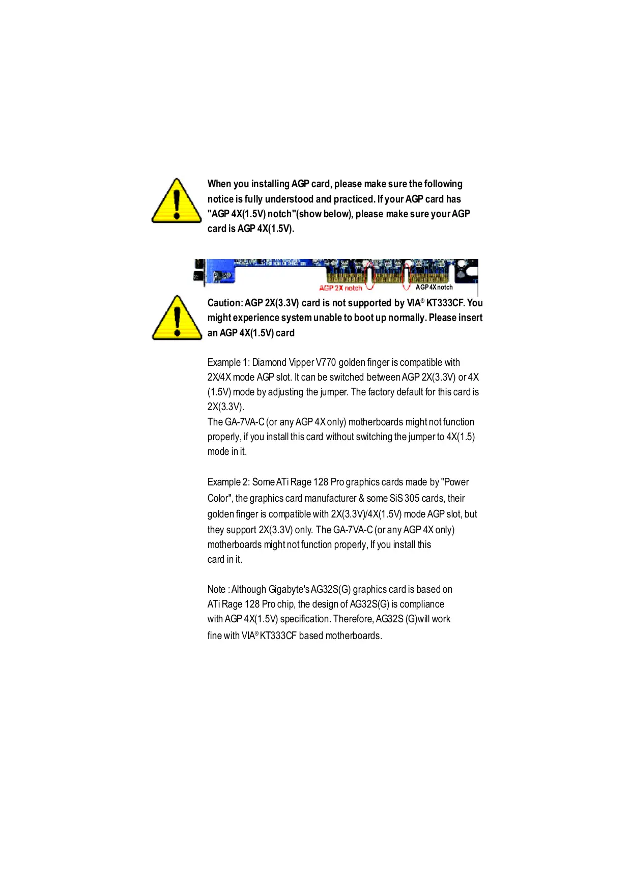
When you installing AGP card, please make sure the following notice is fully understood and practiced. If your AGP card has "AGP 4X(1.5V) notch"(show below), please make sure your AGP cardis AGP 4X(1.5V). AGP4Xnotch AGP 2X notch Caution: AGP 2X(3.3V) card is not supported by VIA® KT333CF. You might experience system unable to boot up normally. Please insert an AGP 4X(1.5V) card Example 1: Diamond Vipper V770 golden finger is compatible with 2X/4X mode AGP slot. It can be switched between AGP 2X(3.3V) or 4X (1.5V) mode by adjusting the jumper. The factory default for this card is 2X(3.3V). The GA-7VA-C (or any AGP 4X only) motherboards might not function proper, if you install this card without switching the jumper to 4X(1.5) mode in it. Example 2: Some ATi Rage 128 Pro graphics cards made by "Power Color", the graphics card manufacturer & some SiS 305 cards, their golden finger is compatible with 2X(3.3V)/4X(1.5V) mode AGP slot, but they support 2X(3.3V) only. The GA-7VA-C (or any AGP 4X only) motherboards might not function propery, If you install this card init. Note : Although Gigabyte's AG32S(G) graphics card is based on ATiRage 128 Pro chip, the design of AG32S(G) is compliance With AGP 4X(1.5V) specification. Therefore, AG32S (G)will work fine with VIA®KT333CF based motherboards.
© The author assumes no responsibility for any errors or omissions that may appear in this document nor does the author make a commitment to update the information contained herein. © Third-party brands and names are the property of their respective owners. Please do not remove any labels on motherboard, thismay void the warranty of this motherboard. Due to rapid change in technology, some of the specifications might be out of date before publication of this booklet.
DECLARATION OF CONFORMITY
Responsible PartName: G.B.T. INC. (U.S.A.) Address: 17358 Railroad Street City of Industry, CA 91748 Phone/F ax No: (818) 854-9338/ (818) 854-9339 hereby declares that the product Product Name: Motherboard Model Number:GA-7VA Conforms to the following specifications: FCC Part 15, Subpart B, Section 15.107(a) and Section 15.109 (a),Class B Digital Device Supplementary Information: This device complies with part 15 of the FCC Rules. Operation is subject to the following two conditions: (1) This device may not cause harmful and (2) this device must accept any inference received, including that may cause undesired operation. Representative Person’s Name: ERIC LU Signature: Z'ric Lu Date: November4 ,2002
Chapter 2 Hardware Installation Process... 8
Item Checklist M1 The GA-7VA-C motherboard M 2PortUSB Cable x 1 M IDE cable x 2/ Floppy cable x 1 © 4 PortUSB Cable x 1 EM Motherboard SetingsLabel Audio combo Kit x1 B1 GA-7VA-C users manual D IEEE 1394 Cable x1 D RAID Manual DO SPDIF KIT x1 (SPD Kit M CD for motherboard driver & utlity (Driver CD) O LO Shield M Quick PC Instllaïion Guide /À ER Computer motherboards and expansion cards contain very delicate Integrated Circuit (IC) chips. To protectthem against damage fromstai electriity, you should folow some precaufons whenever you work on your computer.
1. Unplug yourcomputer when working onthe inside.
2. Usea groundedwrist srap before handling computer components. ffyou do nothave
one, touch bothofyourhands to a safely grounded objector to a metalobject such as the power supplycase.
3. Hold component bye edges and trynotbuch he IC chips, leads or connectors, or
4. Place components on a grounded anfstañc pad or on the bag thatcame with he
componens wheneverthe components are separa&d fromthe system.
5. Ensure thatthe ATX power supply is switched offbefore you plug in or remove theATX
power connector on he motherboard. Installing the motherboard to the chassis. Ifhemotherboard has mouning holes.buttheydonttineup wih the holeson he base andthere are nosloë to atachthe spacers, do notbecome alarmed you can sil atach the spacers to he mouning holes. Justcutthe botiom portion ofthe spacers (he spacermaybe alitle hard to cutof, so be careful ofyour hands). In this way you can stllatach he motherboard b the base without worying aboutshort circuits. Someîmes you mayneed to use the plasfc springs b isolaë the screw fomthe motherboard PCBsurface, because the circuitwire may be near by he hole. Be carelul, don'tletthe screw contact anyprind circuitwite or parts on the PCB thatare near he fxing hole, ofherwise itmay damage the boardor cause boardmalfunctoning. GA-7VA-C Motherboard -4-
On-BoardSound Realtek ALC650 CODEC Line Out/ 2frontspeaker Line In /2 rear speaker(by s/w switch) Mic In / center& subwoofer(by s/w switch) SPDIF Out/SPDIF In CD In /AUX In / Game port On-Board USB 2.0 Buïltin VIA VT8235 Chipset PS2 Connector PS/2Keyboard ineriace and PS/2 Mouse interace BIOS Licensed Award BIOS, 2M bitfash ROM Supports Q-Flash AddionalFeaures PS/2 Keyboard power on bypassword, PS/2 Mouse power on External Modem wake up STR(Suspend-To-RAM) Wake on LAN(WOL) AC Recovery Poly fuse for keyboard over-curentprotecion USB KB/Mouse wake up from S3 Supports @BIOS Support EasyTune 4 Overclocking + Over Voltage (DDR/AGP/CPU) by BIOS + Over Clock (DDR/AGP/CPU/PCI) by BIOS Please setthe CPU hostfrequencyin accordance with your processor's specticatons. We don'trecommend you b sethe system bus frequency overthe CPU's specifcaton because these specific bus frequencies are notthe standard specticaons for CPU, chipsetand mostofthe peripherals. Whether yoursysim can run under these specific bus frequencies properiy will depend on yourhardware configurations, including CPU, Chipsets SDRAM,Cards….etc. GA-7VA-C Motherboard -6-
pter 2 ware Installation Process To set up your computer, you must complete the following steps: Step 1- SetDip Switch (CK_RATIO) and system Switch (SW1) Step 2-Install the Central Processing Unit (CPU) Step 3- Install memory modules Step4- Install expansion cards Step 5-Connect ribbon cables, cabinet wires, and power supply Step 6- Setup BIOS software Step 7- Install supporting software tools Step2 Step 5 Step 4 —— GA-7VA-C Motherboard -8-
Step 1: Install the Central Processing Unit (CPU) Step1-1: CPU Speed Setup Thesystem bus frequency can be swiched at 100/133/166MHz by adjusting system switch (SW1). (The internal fequencydepend on CPU.)
2. Locate Pin 1 in he socketand look
fora (golden) cutedge on tie CPU upper comer. Theninsertthe CPU inb he socket
1. Pull up he CPU socket lever
andupto 90-degreeangle. © Please make sure the CPU type is supported by the motherboard. © If you do not match the CPU socket Pin 1 and CPU cut edge well, it will cause improper installation. Please change the insert orientation. GA-7VA-C Motherboard -10-
Step1-3:CPU Heat Sinkinstallation
1. Press down the CPU socket
lever and fnish CPU insallato:
3. Fasknhehea&inksupporing-base 4. Make sure te CPU fan is
ontothe CPUsocketon the main- plugged tothe CPUfan connecbr, board. thaninstllcomplet. © Please use AMD approved cooling fan. © We recommend you to apply the thermal paste to provide better heat conduction between your CPU and heatsink. © Make sure the CPU fan power cable is plugged in to the CPU fan connector, this completes the installation. © Please refer to CPU heat sink user's manual for more detail installation procedure. -11- Hardware Installation Process
DIMM slot Then push it down.
3. Close the plastcclip atboth edges oftheDIMM slots
© When DIMM LED is ON, do notinstall/remove DIMM from socket. © Please note thatthe DIMM module can only fitin one direction due to the one notches. Wrong orientation will cause improper installation. Please change the insertorientation. GATVA-C Motherboard T7
DDR Introduction Estblished on the existing SDRAM industry infrastructure, DDR (Double Data Rate) memory is a high performance and costeffctve solution thatallows easy adoption formemoryvendors, OEMs and systemintegrabrs. DDR memoryis a sensible evoluionary solufon for he PC industry that builds on the existing SDRAMinfasrucUre, yetmakes awesome advances in solving he system perbrmance botleneckby doubling the memory bandwidth. DDR SDRAM will offer a superior solution and migration path from existing SDRAM designs due to its availability, pricing and overall market support PC2100 DDR memory (DDR266) doubles he dataraë hrough reading and wrifng atboth the rising and faling edge of the clock, achieving data bandwidih 2X greaterthan PC133 when running with he same DRAM clock frequency. Wih peak bandwidh of2.664GB persecond, DDR memoryenables system OEM to build high performance and lowlatency DRAM subsystems thatare suitable for servers, worksätons, high- end PC's and value desktop SMA systems. With a core voltage ofonly 2.5 Volts compared to conventional SDRAM's 3.3 volts, DDRmemoryis a compeling solution for small fom factor deskiops andnotebookapplicatons. Step 3: Install expansion cards
1. Readthe related expansion card's instruction documentbefore installthe expansion card into
the computer. Remove your computers chassis cover, necessaryscrews and slotbracketfrom he compur. Press the expansion card frmly into expansion slotin motherboard. Besure he metalconäcts on the cardare indeed seaëd in the slot Replace the screw to secure he slotbracketofthe expansion card. Replace your compu&r's chassis cover. Power on the computer, ifnecessary, setup BIOS ufiltyof expansion cardfrom BIOS. Insäll related driver fom the operaing system. DIRES R Please carefully pullouthe small white- drawable bar atthe end ofthe AGP slotuhen you try to install/Uninstall he AGP card. Please align the AGP card tothe onboard AGP slotand press firmly down onthe slot. Make sure your AGP card is locked by the small whie- drawable bar. AGP Card -13- Hardware Installation Process
Step 4: Connect ribbon cables, cabinet wires, and power supply Step4-1 : 1/0 Back Panel Introduction o|9 ] PS/2 Mouse Connector > This connector supports standard PS/2 (6pin Female) keyboard and PS/2 mouse. \ PS/2Keyboard Connector } (Gpin Female)
@ USB Connector > Before you connectyour device(s) into USB connector(s), please make sure your device(s) suchas USB keyboard, mouse, scanner, zip, speaker..etc. Have a standard USB interface. Also make sure your OS supports USB controller. fyour OS does notsupport USB controller, please contactOS vendorfor possible patch ordriver upgrade. For more inbrmañon please contactyour OS or device(s) vendors. GA-7VA-C Motherboard -14-
© Parallel Port ,VGA port and Serial Ports (COMA) > This connectorsupports 2 standard COM por and 1 Parallel port Device like printer can be connected to Parallel Port (25 pin Female) Parallel port; mouse and modem et can be connected to Serial ports. COMA COMB Serial Ports (9 pin Male) © Game /MIDI Ports > Thisconnecbr supports joystick, MIDI keyboard and otherrelab audio devices. Joystck/ MIDI (15 pin Female) © Audio Connectors > Afer instal onboard audio driver, you may connect speaker to Line Outjack, micro phone to MIC In jack. Device Ike CD-ROM , walkman et can be connected gen gen | to Line-in jack. | Plasenoë: You are able to use 2-/4-/6-channelaudio feature by Line Out MC n (Front (Center and Subwoofer) SWselkcion. Speaker) Hyou wantio enable 6-channel function, you have 2 chooseforhardware connection. Line In Method: (RearSpeaker) Connect ‘Front Speaker” to ‘Line Out’ Connect‘Rear Speaker” io “Line In” Connect“Center and Subwooferr” io “MIC Out“. Method2: You can refer b page 20, and contactyournearestdealer for opional SUR_CEN cable. ffyou want the detail information for 2-/4-/6-channel audio setup installation, please © referto “2/4-6-Channel Audio Function Introduction” -15- Hardware Installation Process
4)IDE1/ IDE2 (IDEA/IDE2 Connector) > ImportantNoice: Please connectfrstharddisk to IDE1 and connect CDROM to IDE2. The red stipe ofthe ribbon cable mustbe he same side with fe Pin1. IDE1 5)FDD (Floppy Connector) > Please connecthe foppydrive nibbon cables to FDD. Itsupports 360K,720K,1.2M,1.44M and 2.88Mbytes floppy disk types. The red stipe ofthe ribbon cable mustbe he same side with fe Pin1. 6)RAM_LED > Do notremove memory modules while DIMM LEDis on. ltmightcause shortor oherunexpected damagesdue the 2.5V stand by voltage. Remove memory modules onlywhen AC Power cord is
disconneckd. 7)PWR_LED > PWR_LEDis connectwith the system power indicator to indicate whether the system is onof. itwill blink when the system enters suspendmode. “r fyou use dual color LED, power LED will turn 1 tanother color. GATVA-C Motherboard TE
10)F_AUDIO (F_ AUDIO Connector) > lfyou wantto use FrontAudio connector, you mustremove 5-6, 9-10 Jumper. Inorderto utilze the fontaudio header, your RearAudio(L) se FrontAudio (L) chassis musthave font audio connector. Also 0—+— Resened please make sure the pin assigmenton he RearAudio (R) —| D arAucio(R —[ono| FrontAudio (R) … cableis he same as he pin assigmenton POWER LR GND c MIC the MB header. To fndoutifhe chassis you 1 are buying supportfrontaudio connector, please contactyour dealer. 11)SUR_CEN > Please contactyournearestdealerforoptonal SUR_CEN cable.
GA-7VA-C Motherboard
OS Setup BIOS Setup is an overview of the BIOS Setup Program. The program that allows users to modify the basic system configuration. This type of information is stored in battery-backed CMOS RAM so thatit retains the Setup informañon when the power is turned off. ENTERING SETUP Aflr power on the computer, pressing <Del>immeditely duringPOST (Power On SafTest)itwil allow youto enterstandardBIOS CMOS SETUP. Ifyou require more advanced BIOS settings, please go to “adv anced BIOS" seting menu.To enter Advanced BIOS setting menu, press “Ctr+F1” key on the BIOS screen. CONTROL KEYS <w Move to previous item <> Move to next item <e Move to the item in the left hand <>> Move to the item in the right hand <Esc> Main Menu - Quit and not save changes into CMOS Status Page Setup Menu and Option Page Setup Menu - Exit current page and return to Main Menu <+/PgUp> Increase the numeric value or make changes <-/PgDn> Decrease the numeric value or make changes <F1> General help, only for Status Page Setup Menu and Opion Page Setup Menu <F> Item help <F3 Reserved <F4> Reserved <F5> Restore the previous CMOS value from CMOS, only for Option Page Setup Menu <F6> Load the default CMOS value from BIOS default table, only for Opion Page Setup Menu <FT> Load the Setup Defaults <F& Q-Flash <F9> Reserved <F10> Save all the CMOS changes, only for Main Menu -B- BIOS Setup
GETTING HELP Main Menu The on-line description of the highlighted setup function is displayed at the bottom of the screen. Status Page Setup Menu / Option Page Setup Menu Press F1 to pop up a small help window that describes the appropriate keys to use and the possible selections for the highlighted item. T exit the Help Window press <E sc>. The Main Menu (For example: BIOS Ver. : F6) Once you enter Award BIOS CMOS Setup Utility, the Main Menu (Figure 1) will appear on the screen. The Main Menu allows you to select from eight setup functions and two exit choices. Use arow keys to select among the items and press <Enter> to accept or enter the sub-menu. CMOS SetupUiliy-Copyright(C) 1684-2002 Award Sof are > Standard CMOS Features TopPerformance DAdvancedBIOS Feaures Load Fail-Safe Defaults PIntegratedPeripherals Load Optimized Defaults >Power Management Setup SetSupervisor Password > PnP/PCI Configurations SetUserPassword »PC Healh Status Save & ExitSetup > Frequency/Voltage Control ExitWithout Sav ing ESC:Quit TI: Selectiem F8QFlash FH0:Save& Exit Setup Time, Date, Hard Disk Ty pe. Figur 1: MainMenu If you can't find the setting you want, please press "Ctri+F1” to search the advanced option widden. e Standard C MOS Features This setup page includes all the items in standard compatible BIOS. e Advanced BIOS Features This setup page includes all the items ofAward special enhanced features. e Integrated Peripher als This setup page includes all onboard peripherals. GA-\A-C Motherboard -24-
Power Management Setup This setup page includes all the items of Green function features. PnP/PCI Configurations This setup page includes all the configuraäons of PCI & PnP ISA resources. PC Health Status This setup page is the System auto detect Temperature, voltage, fan, speed. Frequency/Voltage Control This setup page is control CPU's clock and frequency ratio. Top Performance Top Performance Defaults indicates the value of the sy stem parameters which the sy stem would be in best performance configuration. Load Fail-Safe Defaults Fail-Safe Defaults indicates the value ofthe system parameters which the system would be in safe configuraton. Load Optimized Defaults Opfmized Defaults indicates the value ofthe system parameters which the system would be in better perfomance configurafon. Set Supervisor password Change, set, or disable password. Itallows you to limit access to the sy stem and Setup, or just to Setup. Set User password Change, set, or disable password. Itallows you to limit access to the system. Save & Exit Setup Save CMOS value setings to CMOS and exit setup. Exit Without Saving Abandon all CMOS value changes and exit setup. 5 BIOS Setup
Standard C MOS Features CMOSSetupUtliy-Copyright(C) 1684-2002 Award Sofiare Standard CMOS Features Date (mm:dd:yy) Thu, Feb 21 2002 lem Help Timelhhmm:ss) 223124 MenuLeva D PIDE Primary Master [Press Enter None] Change day month PIDEPrimary Save [Press Enter None] year PIDESecondary Master [Press Enter None] <hek >IDESecondary Save [Press Enter None] Sun.» Sat DrireA [144M, 357] <Month> DrveB [Nore] Jan. b Dec. Flopoy 3 Mode Support [Dsabkd] <Day> 10 81(rmatmun alowed Halt On [AI ButKey board] ithemonth.) BaseMemay 640K qe ExtendedMemary 130048K 19102008 TotlMemory 131072K Ti<: Move EnterSelect +//PU/PD:Vaue F10:Save ESC:Exi F1: General Help F5:Previous \alues F6:Fai-Safe Defauls F7:Optimized Defaults Figure 2: Sendard CMOS Feaures + Date The date format is <week>, <month>, <day>, <year>. » Week Theweëk, from Sun b Sat, detemined by the BIOS andis display only # Month Themonth, Jan. Through Dec. Day Theday, from 1 to 31 (or he maximum allowed in he month) » Year Theyear, from 1999 through 2098 Time The times format in<hour> <minute> <second>. Thetime is calculated base on the 24-hour miliery- ‘me clock. Forexample, 1 pm. 5 13:00:00. GA-\A-C Motherboard -6-
+ IDE Primary Master, Slave / Secondary Master, Slave Thecategory identes the types of hard disk from drive C to F thathas been installed in the computer. There are wo types: auto type, and manual type. Manual pe is userdefineble; Auto #pewhichwillautomaticaly detectHDD type. Nob thatthe specifcations ofyourdrive mustmatchwith he drive table. The hard disk will notwork properiy f you enter improper information br this category . lfyou selctUser Type, relaëd infomatonwill be asked to enter tothe folowingitems. Enterthe information directy fromthe keyboard and press <Enter. Suchinformalion should be provided in thedocumentaton fom yourhard disk vendoror the system manufacturer. » Capaci Thehard disk size. The unitis Mega Bys. wAccessMode: Theoptions are: Auto/ Large/ LBA/ Nomal. » Cylnder Thecylinder number ofhard disk. »Head Theread /Wite head number ofhard disk. »Prcomp Thecylner numberatwhich tre disk driver changes the witecurrent » Landing Zone Thecylinder number hatthe diskdriver head (read/w rite) areseated whenthe disk driveis parked. » SECTORS Thesector numberof eachtrack defineon thehard dsk. Ifa hard disk has not been installed select NONE and press <E ner + Drive A / Drive B The category idenfifies the ty pes of floppy disk drive À or drive B that has been installed in the computer. None Nofoppy driveinstalled »>360K, 5.25". 5.25 inch PC-typestandard drive; 360K byte capaciy . »12M,5.25. 5.25 inch AT-type high-densty div e; 1.2M byle capacity (8.5inchwhen 3 Mode is Enabled). »720K,3.5°. 3.5inchdouble-sided d'ive; 720Kby te capacity »144M,3.5". 3.5inchdouble-sideddriv e; 1.44M by te capacity . »>2.88M,3.5". 3.5inchdouble-sideddrive; 2.88M by te capacity . + Floppy 3 Mode Support (for J apan A rea) »Disæbled Nomal Flppy Drive. (Defaut value) »DriveA Enabkd 3 mode function of Drive A. »DriveB Enabkd 3 mode functien ofDrive B. »Both Drive A& Bare3 mode Floppy Drives. te BIOS Setup
+ Halt on The category determines whether the computer will stop ifan error is detected during power up. »NOErors Thesystem bootwil| notstopfor any error thatmay be detected and you will beprompted. WA Errors Wnenever the BIOS detects anon-faël errorthe system will be stopped. » Al ButKeyboar | Thesystem bootwil rotstop for a key board error: itwil stopfor alloher errors. (Defaultv lue) »Al, ButDiskete Thesystem bootwil notstop bra disk error: itwill stop forall othererrors. »AlLButDisk/Key | Thesystem boctwill notstop br akey board or diskerror, itwill Stop for all othererrors. Memory The category is display-only which is determined by POST (Power On Self Test) of the BIOS. Base Memory The POST of the BIOS will detemine the amount of base (or conventional) memory installed in the system. The value of the base memory is typically 512 K for sy stems with 512 K memory installed on the motherboard, or 640 K for systems with 640 K or more memory installed on the motherboard. Extended Memory The BIOS determines how much extended memory is pres ent during the POST. This is the amount of memory located above 1 MB in te CPU's memory address map. GA-\A-C Motherboard -2B-
Advanced BIOS Features CMOSSetupUiliy-Copyright(C) 1884-2002 Award Sofiware Advanced BDS Features First Boot Device Forpy] em Help Second Boot Device [HDD-0] Maude Third Boot Device ICOROM] Boot Up Floppy Seek [Disabed] PasswordCheck [Sup] InitDisplay First AGP] Ti<: Move Enter Select +/PU/PD:Vaue F10:Save ESC:Ext F1:Geneal Help F5:Previous \alues F6:Fai-Safe Defauls F7:Optimized Defaults Figure 3: Advanced BIOS Feaures < First/ Second / Third Boot device 6 Ths feaure alows you toselectihe boot device priorty . »Fioppy Sekctyourbootdevicepriodity by Floppy »LS120 Sekctyour boot device priority by LS120 »HDD-0-3 Selectyour bootdevice prioity by HDD-0-3. SCSI Sekct your boot device priority by SCSI. » CDROM Sekctyour bootdeviceprioity by CDROM. LAN Sekctyour boot device priority by LAN. »USB-CDROM Sekctyour bootdvicepriaity by USB-CDROM. wUSB-ZP Sekctyourbootdevice prority by USB-ZIP. wUSBFDD Sekctyourbootdevice prority by USB-FDD. »USB-HDD Sekctyourbootdeice pioriy by USB-HDD. wZP Sekctyour boot device priority by ZIP. wDisæled Disabled is function. 2 BIOS Setup
+ Boot Up Floppy Seek € During POST, BIOS wil determine thefoppy disk drive installed is 40 or 80 tracks. 360 K pe is 40 tracks 720 K 1.2 M and 1.44 M æe al 80tracks. »Endbled BIOSsearches fa floppy disk drive to determine it is 40 or80 tacks. Note thatBIOS can not tel from 720 K 1.2 M or 1.44 Mdrive type as they are all80tracks. wDisdled BlOSwillnotsearchforthe pe o floppy disk diive by track number. Note thatihere wilinot beany warning message ifhe drive installed is 360 K. (Défaut value) + Passwor dCheck » System The system can not boot and can not access to Setup page will be denied ifthe comect password is notentred atthe prmpt. »> Setup Thesystem willboot, butaccess to Setup wil be deniedif the correct passwordis notenred atthe prompt (Default vaue) + InitDisplay First € This feature allows you to select the firstinitation of the monitor display from which card, when you install an AGP VGA card and a PCI VGA card on board. »PCI Sethit Display Firstto PCI Slot. AGP Set hitDispay Firstto AGP. Default value) GA-\A-C Motherboard -3-
+ AC PI Suspend Type »S1POS) Setsuspend type to Power On Suspend under ACPIOS(Power OnSuspend). (Defaut value) »SASTR) Setsuspend type to Suspend To RAM under ACPIOS (Suspend To RAM) <-USB Device Wakeup From S3(When AC PI Suspend Type is set [S3(S TR)]) USB device wakeup From S3 can be set when ACPI standby state set to S3/STR. » Enebled USB Device canw akeupsy sem fom S3. »Disæbled USBDev ie can't wakeupsy stem fom S3. (Default value) + Power LED in S1 State » Binkhng In standby mode(S), power LED wi birk. (Deäult Vaue) » DuallOf In standby mode(S1): a. Fuse single cdbor LED, power LEDwil tumof. b. Fuse dual colorLED, power LED will tun to another color. + Soft-off by PWRB'IN » Instantoff Press pourer button then Power offinstanty. (Default value) »Deky 4 Sec. Press power button 4 sec to Powerof. Enbr suspend ifbuttonis pressediess thand sec. + AC Back Function Memory Systm power on depends on thestatus before AC bst »Soft-Of AWways in Offstatewhen AC back. (Défaut vale) »Ful-On Alrays poweronthe system when AC back. + Keyboard Power On This feature allows you to set the method for powering-on the system. The option “Password‘ allows you to set up to 8 alphanumeric characters to power-on the system. The opüon “Any Key” allows y ou to touch the key board to power on the system. The option “Keyboard 98° allows you to use the standard keyboard 98 to power on the system. » Password Enërfram 1 to 8 characters to setthe Key board Power OnPassword »Disæbled Disabled his funcion. (Defaultvalue) wkeyboard98 | fyourkeyboardhave *POWERKey" buton, youcanpress thekey to power onyour system. GA-\A-C Motherboard -%-
+33V 3.80V +sv ago H2V 11.968 svsB 5.63 CurrentSystem Temperature 2° Current CPU FAN Speed 3183RPM Curent SYSTEM FAN speed ORPM CPUFAN Fal Waming [Dsabkd] SYSTEM FAN Fai Warning [Dsabkd] CPUShutdownTemperaure [Dsabkd] Current CPU Temperaure 34CIF Ti<: Move Enter Select +/PU/PD:Vaue F10:Save ESC:Ext F1:Geneæal Help F5:Previous \alues F6:Fai-Safe Defauls F7:Optimized Defaults Figure7: PC Health Status Reset Case Open Status Case Opened the cæse is closed, "Case Opened" will show “No”. Ifthe case have been opened, "Case Opened"will show "Yes". fyou wantto reset"Case Opened" value, set'Reset Case Open Status" to "Enabled” and save CMOS, your computer will restart. # Current Voltage (V) VCORE/DDRVtt/ +3.3V/ +5V /H2V / 5VSB Detectsystem's voltage status automatically. KE BIOS Setup
Set Supervisor/User Password CMOS Setup Utity-Copy right (C) 1984-2002 Aw ard Sofware > Standard CMOS Feaures TopPerormance > Advanced BIOS Features Load F ail-Safe Defaults Integrated Peripherals Load Opimized Defaults > Power Management Setup SetSupervisor Password > PnP| »PCH > Frequency/Voltage Control ExitWithout Saving ESC:Quit TI €: Selectiiem F&QFlash F10Save& Exit Saup Change/Set/DisablePassword Figure 13: Password Seting When you select this function, the following message will appear at the center of the screen to assist you in creaïng a password. Type the password, up to eight characters, and press <Enter>. You will be asked to confirm the password. Type the password again and press <Enter>. You may also press <Esc> to abort the selection and not enter a password. To disable password, just press <Enter> when you are prompted to enter password. À mess age “PASSWORD DISABLED” will appear to confirm the password being disabled. Once the password is disabled, the system will boot and you can enter Setup freely. The BIOS Setup program allows you to specify two separate passwords: a SUPERVISOR PASS- WORD and a USER PAS SWORD. When disabled, anyone may access all BIOS Setup program function. When enabled, he Supervisor password is required for entering he BIOS Setup program and having full configuration fields, he User password is required to access only basic items. If you select “System” at “Security Opion” in Advance BIOS Features Menu, you will be prompted for the password every time the system is rebooted or any time you try to enter Setup Menu. Ifyou select “Setup” at “Security Opion” in Advance BIOS Features Menu, you will be prompted only when you ty to enter Setup. GA-\A-C Motherboard -46-
We use GA-7VTX motherboard and Flash841 BIOS fash uiliy as example. Please fash he BIOS according to he bllowing procedures ifyou are now underthe DOS mode. Flash BIOS Procedure: STEP 1: (1) Please make sure yoursystem has installed he extraction ufliy such as winzip or pkunzip. Firsty you have to install he extraction uilitysuch as winzip or pkunzip for unzip the fles. Both of these uilites are available on many shareware download pages like htp/\mww..cnetcom STEP 2: Make a DOS boot diskette. (See example: Windows 98 O.S.) Beware: Windows ME/2000 are notalowed b make a DOS bootdisketk. {1) Wih an avaïable floppy disk in he foppy drive. Please leave the diskette "UN:wri protected" type. Double cick the "My Computer’ icon fom Deskbp, then click "3.5 diskette (A)" and right click to select "Format (M)" “Pro
(2) Selectthe "Quick (erase)" for Format Type, and pick both "Display summary when finished" and "Copy system files", afler hatpress "Star. Thatwill formatthe floppy and transfer the needed system fles to it Beware: This procedure will erase all the prior data on thatfoppy, so please proceed accordingly. Format - 24 TODDy (A [21xI cancers Fummsst Oher prions Label S——— r'Ahiatel F Biephey cunenary non finchoë DEC (3) After the floppy has been formatted completely, please press "Close". ET ; Fimo One cs (TRE «| 220 pr [ HSaarunan none 4 Ds eus eemabb nan CETPEN F am Arr de mit 1206 4F28 con moi -53- Technical Reference
STEP 3: Download BIOS and BIOS utility program. (1) Please go to Gigabyte website htip:/\www gigabyte .com.tw/index.html, and click “Support”. (2) From Supportzone, click the "Motherboards BIOS & Drivers". GA-TVA-C Motherboard -54-
(3) We use GA-7VTX motherboard as example. Please select GA-7VTX by Model or Chipset opfonal menu to obtain BIOS flash filles. (4) Selectan appropriate BIOS version (For example: F4), and click to download the île. Hwill pop up a fle download screen, then selectthe "Open this flle from its currentlocaton" and press"OK". -55- Technical Reference
(5) Atihis âme the screen shows the following picture, please click "Extract' bution to unzip he îles. ÉCTE etre EE vs (6) Please extractthe download îles into the clean bootable floppy disk À mentioned in STEP 2, and press "Extract”. GA-TVA-C Motherboard -56-
STEP 4: Make sure the system will boot from the floppy disk. (1) Insertthe floppy disk (contains bootable program and unzip flle) into the floppy drive A. Then, restart he system. The system will bootfrom the floppy disk. Please press <DEL> key to enter BIOS setup main menu when system is boot up. 9 American Mogatend op0r-a0 169-0010 (2) Once you enter he BIOS setup uflity, the main menu will appear on the screen. Use the arrows to highlightthe item "BIOS FEATURES SETUP".
AMIBIOS SIMPLE SETUPUTILIY - VERSION 1.24D
(C) 1999 American Megatends, Inc. Al Rights Reserved
LOAD SETUP DEFAULTS EXT WITHOUT SAVING
LOAD SETUP DEFAULTS EXIT WITHOUT SAVING
ESC: Quit Ti :Select tem {Shif)F2 : Change Color F5: Old Values F6: Load BIOS Defaults F7:Load Setup Defauls F10:Save & Exit Save Data to CMOS & Exit SETUP GA-TVA-C Motherboard -58-
STEP 5: BIOS fashing. (1) Afer the system bootfrom floppy disk, type "A:P dirw" and press "Enter" to check the entre les in foppy À. Then type the "BIOS fash utility" and "BIOS file" after A. In this case you have to type "A\> Flash841 7VTX.F4" and then press "Enter". Staring Windows 98... Microsof{(R) Windows98 © Copyright Microsoft Corp 1981-1999 Ab dirw Volume in drive Ahas no label Volume Serial Number is 16EB-353D Directory of A
3fle(s) 838,954 byes 0 dir(s) 324,608 bytes free A Flash841 7VTX.F4 (2) Now screen appears the following Flash Uflity main menu. Press "Enter", the highlighted item will locate on tre model name ofthe right-upper screen. Right afer that press "Enter" to start BIOS Flash Utility. -59- Technical Reference
(3) Itwill pop up a screen and asks "Are you sure to fash the BIOS?" Press [Enter] to continue theprocedure, or press [ESC] to quit Beware: Please do notturn offthe system while you are upgrading BIOS. twill render your BIOS corrupted and system totally inoperatve. Are you sure to flash the BIOS? [Enter] to continue Or [Esc] to cancel? [Enter] to continue Or [Esc] to cancel? GA-TVA-C Motherboard -60-
STEP 6: Load BIOS defaults. Normally the system redetects all devices after BIOS has been upgraded. Therefore, we highly recommend reloading the BIOS defaults afer BIOS has been upgraded. This important step resets everything afer the flash. (1) Take outthe floppy diskette from floppy drive, and then restartthe system. The bootup screen will indicate your motherboard model and current BIOS version. 9 American Mega soontte op0r-a0 169-0010 (2) Don'tforget to press <DEL> key to enter BIOS setup again when system is bootup. Use the arrows to highlight the item "LOAD SETUP DEFAULTS" then press "Enter". System will ask "Load Setup Defaults (Y/N)?" Press "V' and "Enter" keys to confirm. AMIBIOS SIMPLE SETUP UTILITY - VERSION 1.24b (C)2001 American Megatrends, Inc. All Rights Reserved
LOAD SETUP DEFAULTS EXIT WITHOUT SAVING
(3) Use the arrows to highlight the item "SAVE & EXIT SETUP" and press "Enter". System will ask "SAVE to CMOS and EXIT (Y/N)?" Press "Y' and "Enter keys io confirm. Now the system will reboot automañically, he new BIOS settng will be taken effect nextboot-up. AMIBIOS SIMPLE SETUP UTILITY - VERSION 1.24b (C)2001 American Megatrends, Inc. All Righis Reserved
LOAD SETUP DEFAULTS EXIT WITHOUT SAVING
ESC: Quit Ti :Select tem {Shif}F2 : Change Color F5: Old Values F6: Load BIOS Defaults F7:Load Setup Defauts F10:Save & Exit Save Data to CMOS & Exit SETUP (4) Congratulate you have accomplished the BIOS fash procedure. GA-TVA-C Motherboard -62-
LD Mehod2: Q-Flash Introduction A. What is Q-Flash Utility? Q-Flash utlity is a pre-O.S. BIOS flash utility enables users to update its BIOS within BIOS mode, no more foling around any OS. B. Howto use Q-Flash? a. Afer power on the computer, pressing <Del> immediately during POST (Power On Self Test) it will allow you to enter AWARD BIOS CMOS SETUP then press <F8> to enter Q-Flash utility. CMOS Setup Utlty-Copyright(C) 1984-2002 Award Sofware Standard CMOS Feaiures TopPerformance +Advanœed BIOS Features Load Fail-Safe Defaulis DIntegrated Perinhera Load Ontimized Default Enter Q-Flash Uiity (Y/N)? Y. ave & EXT SELIP Exit Wihout Saving TV <:Selectiiem F10:Save & Exit Setup Time, Date, Hard Disk Type. b. Q-Flash Utility Q-Flash Utility V3.05 Flash Type/Size : SST39SF020 /256K Keep DMIData : Yes Load BIOS from Floppy Save BIOS to Floppy Space Bar:Change Value Enter: Run ESC: Reset T/L: Select liem -63- Technical Reference
Load BIOS From Floppy #n the A:drive, insertthe "BIOS" diskette, then Press Enter to Run. 1 File(s) fund Total Size: 1.39M Free Size: 1.14M F5: Refresh DEL: Delete ESC: Retum Main Where XXXX.XX is name ofthe BIOS file. #Press Enter io Run. #Press Enter io Run. Congratulaton! You have completed the flashed and now can restart system. GA-TVA-C Motherboard -64-
1. Update BIOS through Internet
a. Click "Internet Update" icon b. Click "Update New BIOS" icon c. Select @BIOS" sever d. Selecthe exact modelname on your moherboard e. System will automatically download and update the BIOS. -65- Technical Reference
Il. Update BIOS NOT through Internet a. Do notclick "Internet Update" icon b. Click "Update New BIOS" c. Please select"All Files" in dialog box while opening the old flle. d. Please search for BIOS unzip file, downloading from internet or any other methods (such as: 7VAF6). . Complete update process following the instruction.
Ill. Save BIOS In the very beginning, there is "Save Current BIOS" icon shown in dialog box. ltmeans to save the current BIOS version.
IV. Check outsupported motherboardand Flash ROM:
In the very beginning, there is "About this program" icon shown in dialog box. lt can help you check outwhich kind ofmotherboard and which brand ofFlash ROM are supported. Note: a. In method | ifitshows two or more motherboard's model names to be selected, please make sure your motherboard's model name again. Selecing wrong model name will cause the system unbooted. .. In method Il, be sure that motherboard's model name in BIOS unzip flle are the same as your motherboard's. Otherwise, your system won'tboot . In method | ifthe BIOS file you need cannot be found in @BIOS"" server, please go onto Gigabyte's web site for downloading and updafng itaccording to method Il. . Please not thatany interrupüon during updatng will cause system unbooted
@ BIOS Intro Gigabyte announces @ BIOS Windows BIOS live update utility Have you ever updated BIOS by yourself? Or like many other people, you just know what BIOS is, @ ECS butalways hesitate to update if? Because you think updaing newest BIOS is unnecessary and BIOS Live Update Utility actually you don'tknow how io update it Maybe notlike others, you are very experienced in BIOS updaïng and spend quite a lotof time t do it But ofcourse you don'tlike to do ittoo much. First, download different BIOS from website and then switch the operaïng system to DOS mode. Secondiy, use different flash utlity to update BIOS. The above process is nota interesting job. Besides, always be carefully to store he BIOS source code correcty in your disks as ifyou update the wrong BIOS, itwill be a nighimare. Certainly, you wonderwhy motherboard vendors could notjust do something right io save your ime and effortand save you from the lousy BIOS updaïng work? Here itcomes! Now Gigabyte announces @BIOS—the first Windows BIOS live update uflity. This is a smart BIOS update sofware. lt could help you to download the BIOS from interetand update it Notlike te other BIOS update sofware, its a Windows utility. With the help of“@BIOS', BIOS updaïng is no more than a click. Besides, no matter which mainboard you are using, ifits a Gigabyte's product‘, @BIOS help you to maintain the BIOS. This utility could detect your correctmainboard model and help you to choose the BIOS accordingly. then downloads the BIOS from the nearest Gigabyte fp site automañcally. There are several different choices; you could use “internet Update" to download and update your BIOS direct. Or you may want to keep a backup for your current BIOS, just choose “Save Current BIOS"o save itfrst You make a wise choice to use Gigabyte, and @BIOS update your BIOS smariy. You are now worryfree from updaïng wrong BIOS, and capable to maintain and manage your BIOS easily. Again, Gigabyte's innovatve producterects a milestone in mainboard industries. For such a wonderful sofware, how much itcosts? Impossible! fs free! Now, ifyou buy a Gigabyte's motherboard, you could find this amazing sofware in the attached driver CD. But please remember, connected t intemetat first, then you could have a internet BIOS update from your Gigabyte @BIOS. -67- Technical Reference
Easy Tune!" 4 Introduction Gigabyte announces EasyTune"" 4Windows based Overclocking utility EasyTune 4 caries on the heritage so as to pave the way for future generations. Overclock" might be one ofthe mostcommon issues in computer field. Buthave many users ever tried it? The answer is probably "no". Because "Overclock" is thought to be very dificultand in- cludes a lot of technical know-how, sometimes "Overclock" is even considered as special skills found only in some enthusiasts. Butas to the ex- perts in "Overclock", whats the truth? They may spend qui a lotofime and money to study, try and use many diferenthardware or BIOS tools to do "Overclock". And even with these technologies, theysilllearn hatits quite a risk becausethe safety and stability ofan "Overclock" system is unknown. Now everything is different because of a Win- dows based overclocking utlity "EasyTune 4" --announced by Gigabyte. This windows based utility has totally changed the gaming rule of"Overclock". This is the frst windows based overclocking ulity is suitable for both normal and power users. Users can choose either "Easy Mode" or "Ad- vanced Mode" for overclocking attheir convenience. For users who choose "Easy Mode", they just need to click "Auto Optimize" to have autoed and immediate CPU overclocking. This sofware will then overdrive CPU speed automatically with the resultbeing shown in the control panel. Ifusers prefer "Overclock" by them, there is also another choice. Click "Advanced Mode" to enjoy "sport drive" class Overclocking user ineriace. "Advanced Mode", allows users to change the system bus T'AGP / Memory working frequency in smallincrements to getulimate system performance. itoper- ates in coordination with Gigabyte motherboards. Besides, itis different from other traditonal over- clocking methods, EasyTune 4 doesn'trequire users to change neiïther BIOS nor hardware switch/ jumper seting; on the other hand, they can do "Overclock" ateasy step . Therefore, this is a safer way for "Overclock" as nothing is changed on sofware or hardware. ffuser runs EasyTune 4 over system's limitafion, the biggestlost is only to restartthe computer again and the side effectis then well controlled. Moreover, ifone wel-performed system speed has been tested in EasyTune 4, user can "Save" this setng and "Load" itin nexttime. Obviously, Gigabyte EasyTune 4 has already tumed the "Overclock" technology toward to a newer generation. This wonderiul sofware is now free bundied in Gigabyte motherboard attached in driver CD. Users may make a test drive of "EasyTune 4" to find out more amazing features by hemselves. *Some Gigabyte products are not fully supported by EasyTune 4. Please find the products sup- ported listin the web site. “Any "Overclocking action" is atuser's risk, Gigabyte Technology will notbe responsible for any damage orinstability to your processor, motherboard, or any other components. GA-7VA-C Motherboard -68-
The installation of windows 98SE/2K/ME/XP is very simple. Please follow next step to install the function! 6-Channel Audio Function Intr Stereo Speakers Connection and Settings We recommend that you use he speaker with amplfier to acquire the best sound effectifthe stereo outputis applied. STEP 1: Comectihe stereo speakers orearphone ‘Line Ouf. Line Out STEP2: Afr installation of the audio driver, you !l find an] ” icon on the taskbar's status area. Click the audio icon “Sound Eflec from the windows tray at the botiom of the screen. STEP3: ie Select “Speaker Configuration”, and choose the De RSS ere “2 channels forstereo speakers out put”. 1 ei e asumr d - pd _ Bas | MT" (&_ 2 channels mode for stereo speakers output -69- Technical Reference
4 Channel Analog Audio Output Mode STEP 1 Connectthe front channels to “Line Ouf’ {he rear channels to “Line In”. Line Out Line In STEP2: Afr installation of the audio driver, you !l find fl icon on the taskbar's status area. Click the audio icon “Sound Eflec from the windows tray at the botiom of the screen. STEP3: nt TA pa Select Speaker Configuration”, and choose the “4 ù cmam—— rossimer channels for 4 speakers output’. Cote E Disable “Only SURROUND-KT", and press “OK”. {4 channels mode for: s oulput When the “Environment setings” is “None”, he a ar sound would be performed as stereo mode tar” (2 channels output. Please seledtihe other setings for 4 channels output GA-TVA-C Motherboard -70-
Basic 6 Channel Analog Audio Output Mode Use the back audio panel to connect he audio output wihoutany additionalmodule. STEP: Comecthe front channels “Line Ouf the rear chan- nels “Line In, and the Center/Subwoofer channels to “MIC n°. STEP2: Afr installation of the audio driver, you !l find an] icon on the taskbar's status area. Click the audio icon “Sound Eflec from the windows tray at the botiom of the screen. STEP3: ee Select'Speaker Configuration’, and choose the nes BE r— “6 channels for 5.1 speakers out pur. | intl Disable “Only SURROUND-KIT" and pess “OK” ‘6 channels mode for
Advanced 6 Channel Analog Audio Output Mode (using Audio Combo Kit Optonal Device): (Audio Combo Kit provides SPDIF output port : opäcal & coaxis and SURROUND-KTT : Rear RL & Center/subwoofer) SURROUND-KIT access analog outputto rear channels and Center/Subwoofer channels. ltis he best solufon if you need 6 channel output, Line In and MIC athe same time. "SURROUND-KT" is included inthe GIGABYTE unique "Audio Combo Kif' as picture. STEP 1: Insert the ‘Audio Combo Kif in the back ofthe case and fix it with the screw. STEP2: Connectthe "SURROUND-KIT” to SUR_CEN on the MB. GA-TVA-C Motherboard -72-
STEP3: Connect the frontchannels to back audio panel's “Line Ouf, the rear channels to SURROUND-KIT's REAR RIL, and the Center/Subwoofer channels to SURROUND-KIT's SUB CENTER. STEP4: Click the audio icon "Sound Effect’ from the windows tray atthe botiom ofthe screen. STEP5: Select"Speaker Configuration", and choose the "6 channels for 5.1 speakers output. Enable “Only SURROUND-KIT" and press "OK". SURROUNDKIT 27 F Only SURROUND-KIT Basic & Advanced 6 Channel Analog Audio Output ModeNotes: When the "Environment setings" is "None", the Sound | mure jou murmure) mom an) va ser would be performed as stereo mode(2 channels output. Please selectthe olher setings for 6 channels output. -73- Technical Reference
SPDIF Output Device (Optional Device A “SPDIF output device is available on the motherboard. Cable with rear bracketis provided and could link to the “SPDIF output connector ? {as picture.) For the furher linkage to decoder, rearbracket provides coaxial cable and Fiber connecäng port
1. Connect the SPDIF output device to the rear
bracket ofPC, and fx itwith screw.
2. Connect SPDIF wire to the motherboard.
3. Connect co-axial or oplical outputto the SPDIF
GA-7VA-C Motherboard
Picture below are shown in Windows XP (CD driver version 1.2) Inserthe driver CD-fle that came with your motherboard into your CD-ROM drive, the driver CD-ïtle willauto startand showthe installaion guide. not please double click he CD-ROM device icon in "Mycompu®r", and execute the setup.exe. À. Installing VIA Chipset Driver Please install this driver as the first priority. his item installs the chipset driver utility hat enableds Plug-n-Plag INF support for Intel chipset component B. Installng Sound Driver Click this item to install sound driver. Appendix A: VIA4 in 1 Service Pack Driver Installation A. VIA 4 in 1 Service Pack Driver Utility: p LE Er L[1.Cick "Vin4in1 Service Pack É
Printto File : Press this bution, you can view fle on the screen . We recommand you do it I there is any problem occurred during USB2.0 device installing, using or upgrading. Please visit Microsoft or GIGABYTE website for dounloading the latest drivers. -79- Appendix
Appendix B: RealTek AC'97 Audio Driver Inserthe driver CD-fle that came with your motherboard into your CD-ROM drive, the driver CD-fte wil auto startand show the instalation guide. ffnot, please double click the CD-ROM device iconin "Mycomputer’, and execute he setup.exe. 1.Click"RealTek AC'97 Audio Driver”.
Labbe mdr toner de 3.Cick "Finish" b restartcomputer. GATVA-C Motherboard T50-
Appendix C: EasyTune4 Utilities Installation Inserthe driver CD-fle that came with your motherboard into your CD-ROM drive, the driver CD-îte wilauto startand show the installation guide. ffnot please double dick he CD-ROM device icon in "Mycompu®r", and execute the setup.exe. LE cick "Easy Tune 4 D (Mainboard Over-clocking Utity) a ds béni ve CEE PORTES me eee RRETEE 5.Cick "Finish" b restartcomputer. -81- Appendix
Technical Support/RMA Sheet (Customer/Country: I Company: [Phone No.: ContctPerson: [E-mail Add. : [Modelname/Lot Number: [pcs revision: BIOS version: SAS: (Configuration Hardware M. Modelname Size: Driver/Utlity: CPU Memory (Brand ideo Card Audio Card HDD CD-ROM / DVD-ROM Modem Network AMR / CNR Keyboard Mouse Power supply (Other Device Problem Description: GA-7VA-C Motherboard -84-
DDRA400 (PC3200) recommended memory modules list Vender Brand Tpe Size Component Status Kingmax Kingmax DDR 128MB KDL684T4AA-50 OK MICRON MICRON DDR 128MB MB8VDDT1664AG-403B2 OK Hynix Hynix DDR 128MB HY5DU28822BT-04 Ok SAMSUNG SAMSUNG DDR 128MB K4H280838D-TCC4 Ok Kingmax Kingmax DDR 256MB KDL684T4AA-50 OK MICRON MICRON DDR 256MB MH6VDDT3264AG-403B2 OK Hynix Hynix DDR 256MB HY5DU28822BT-04 Ok ADATA Winbond DDR 256MB W942508BH-52260D Ok SAMSUNG SAMSUNG DDR 256MB K4H560838D-TCC4223 Ok APACER Winbond DDR 256MB W942508BH-52260D Ok Winbond Winbond DDR 256MB W942508BH-52110A Ok Winbond Winbond DDR 256MB W942508BH-52150D Ok ADATA Winbond DDR 256MB W942508BH-52260D Ok APACER Winbond DDR 256MB W942508BH-52260D Ok © Should you need to find new supportlist, pls refer to http://www.gigabyte.com.tw for the detail. —85- Appendix
Troubleshooting you encounter any trouble during bootup, please follow the troubleshootingprocedures. Tum offhe power and unplughe AC power cable, henremoe al'dfhe add-oncarisandcablesfommotherboari Please male sure motherboard& chassis are notshort? Pleaseisolate theshortpin. Falurehasbeen excluded Makesurethe Please make sure al jumpersetings(suchas CPU system bus jumperseting speed fequencyratio volageand et.jaresetpropety. arecorect Falurehasbeen excluded Plage CPU w cooling fan pone Checkithe CPUcodingfanatachedto CPU properi.is Rene Mg CPU coolingfanpower connectedio CPU_FAN in the AC poner properÿ comecwr
Falurehasbeen excluded Insert and push he memory modue vericaly in he DIMM Yes L Falurehasbeen excluded
1smemoryLED on and CPUfanruming? The problem coud be caused by pouer supply GPU, memery or GPUmemory socket salt
Checkifthere is ésplay. Falurehasbeen excluded Perhaps your VGA card! VGA slt moritx is defective Yes Tumofthe system. Rebootafñer kejboard andmouse have beenpluggedin. Press <Del>to enterBlOS setup. Choose "Load Falurehasbeen excluded is possible at x keyboard or Checkifkeyboard is woñing proper. plie board connect) LS dkoive. Optmized Defaults” and save then exitsetup. Tum ofhe system and e-connectiheIDEcable. Check thesystem can rebootsuccessfuly. Reinstal indows OS, and reinstall add-on cardsandcables. Thentryto rebootihe system Ifhe above procedure unable to sole your problem, please contactwith yourlocal retai distibutor for help. Or, you could submit your question to he service mai via Gigabyte technicalsupportzone {htp:/Mww.gigabyte.com.w). The appropriate response will be provided ASAP. Falurehasbeen e Falurehasbeen excluded The problem vas probably caused by] he IDE device 1 connect or cable xcluded iler ornatonal website —B7- Appendix