 — Motherboard — Mode d'emploi PDF")
Z68A-GD55 (G3) - Motherboard MSI - Free user manual and instructions
Find the device manual for free Z68A-GD55 (G3) MSI in PDF.

User questions about Z68A-GD55 (G3) MSI
0 question about this device. Answer the ones you know or ask your own.
Ask a new question about this device
Download the instructions for your Motherboard in PDF format for free! Find your manual Z68A-GD55 (G3) - MSI and take your electronic device back in hand. On this page are published all the documents necessary for the use of your device. Z68A-GD55 (G3) by MSI.
USER MANUAL Z68A-GD55 (G3) MSI
The material in this document is the intellectual property of MICRO-STAR INTERNATIONAL. We take every care in the preparation of this document, but no guarantee is given as to the correctness of its contents. Our products are under continual improvement and we reserve the right to make changes without notice.
Trademarks
All trademarks in this manual are properties of their respective owners.
MSI® is registered trademark of Micro-Star Int'l Co., Ltd.
NVIDIA® is registered trademark of NVIDIA Corporation.
ATI® is registered trademark of AMD Corporation.
AMD® is registered trademarks of AMD Corporation.
Intel® is registered trademarks of Intel Corporation.
Windows® is registered trademarks of Microsoft Corporation.
AMI is registered trademark of American Megatrends Inc.
Award® is a registered trademark of Phoenix Technologies Ltd.
Sound Blaster® is registered trademark of Creative Technology Ltd.
Realtek® is registered trademark of Realtek Semiconductor Corporation.
- JMicron® is registered trademark of JMicron Technology Corporation.
Netware® is registered trademark of Novell, Inc.
Lucid® is trademark of LucidLogix Technologies, Ltd.
VIA® is registered trademark of VIA Technologies, Inc.
■ ASMedia® is registered trademark of ASMedia Technology Inc.
iPad, iPhone, and iPod are trademarks of Apple Inc.
Revision History
| Revision | Revision History | Date |
| V4.0 | First release for Europe | 2011/05 |
Technical Support
If a problem arises with your system and no solution can be obtained from the user's manual, please contact your place of purchase or local distributor. Alternatively, please try the following help resources for further guidance.
Visit the MSI website for technical guide, BIOS updates, driver updates, and other information: http://www.msi.com/service/download
Contact our technical staff at: http://support.msi.com
Safety Instructions
Always read the safety instructions carefully.
- Keep this User's Manual for future reference.
- Keep this equipment away from humidity.
Lay this equipment on a reliable flat surface before setting it up.
- The openings on the enclosure are for air convection hence protects the equipment from overheating. DO NOT COVER THE OPENINGS.
Make sure the voltage of the power source is at 110/220V before connecting the equipment to the power inlet.
- Place the power cord such a way that people can not step on it. Do not place anything over the power cord.
Always Unplug the Power Cord before inserting any add-on card or module.
All cautions and warnings on the equipment should be noted.
- Never pour any liquid into the opening that can cause damage or cause electrical shock.
If any of the following situations arises, get the equipment checked by service personnel:
The power cord or plug is damaged.
Liquid has penetrated into the equipment.
The equipment has been exposed to moisture.
The equipment does not work well or you can not get it work according to User's Manual.
The equipment has been dropped and damaged.
The equipment has obvious sign of breakage.
DO NOT LEAVE THIS EQUIPMENT IN AN ENVIRONMENT ABOVE 60^ (140^) , IT MAY DAMAGE THE EQUIPMENT.
CAUTION: There is a risk of explosion, if battery is incorrectly replaced.
Replace only with the same or equivalent type recommended by the manufacturer.
警告使用者:
For better environmental protection, waste batteries should be collected separately for recycling special disposal.
FCC-B Radio Frequency Interference Statement
This equipment has been tested and found to comply with the limits for a Class B digital device, pursuant to Part 15 of the FCC Rules. These limits are designed to provide reasonable protection against harmful inter

ference in a residential installation. This equipment generates, uses and can radiate radio frequency energy and, if not installed and used in accordance with the instructions, may cause harmful interference to radio communications. However, there is no guarantee that interference will not occur in a particular installation. If this equipment does cause harmful interference to radio or television reception, which can be determined by turning the equipment off and on, the user is encouraged to try to correct the interference by one or more of the measures listed below.
Reorient or relocate the receiving antenna.
- Increase the separation between the equipment and receiver.
- Connect the equipment into an outlet on a circuit different from that to which the receiver is connected.
Consult the dealer or an experienced radio/television technician for help.
Notice 1
The changes or modifications not expressly approved by the party responsible for compliance could void the user's authority to operate the equipment.
Notice 2
Shielded interface cables and A.C. power cord, if any, must be used in order to comply with the emission limits.
VOIR LA NOTICE D'INSTALLATION AVANT DE RACCORDER AU RESEAU.

Micro-Star International
MS-7681
This device complies with Part 15 of the FCC Rules. Operation is subject to the following two conditions:
1) this device may not cause harmful interference, and
2) this device must accept any interference received, including interference that may cause undesired operation.
WEEE (Waste Electrical and Electronic Equipment) Statement
ENGLISH
To protect the global environment and as an environmentalist, MSI must remind you that...
Under the European Union ("EU") Directive on Waste Electrical and Electronic Equipment, Directive 2002/96/EC, which takes effect on August 13, 2005, products of "electrical and electronic equipment" cannot be discarded as municipal wastes anymore, and manufacturers of covered electronic equipment
will be obligated to take back such products at the end of their useful life. MSI will comply with the product take back requirements at the end of life of MSI-branded products that are sold into the EU. You can return these products to local collection points.

DEUTSCH
Safety Instructions..
FCC-B Radio Frequency Interference Statement. iv
WEEE (Waste Electrical and Electronic Equipment) Statement .
English.
Mainboard Specifications. En-2
Quick Components Guide. En-4
Screw Holes. En-5
CPU (Central Processing Unit) .En-6
Memory .En-9
Power Supply. En-11
Back Panel. .En-12
Connectors. En-14
Buttons. .En-20
Voltage Check Point. En-21
LED Status Indicators . En-22
Jumper. En-23
Slots .En-24
BIOS Setup. En-25
Software Information. En-35
Deutsch De-1
Mainboard Specifications
Processor Support
■ Intel® Core™ i7/ Core™ i5 /Core™ i3/ Pentium®/ Celeron® processor in the LGA1155 package (For the latest information about CPU, please visit http://www.msi.com/service/cpu-support)
Chipset
Intel® Z68 (B3) chipset
Memory Support
4 DDR3 DIMMs support DDR3 2133(OC)/ 1600(OC)/ 1333/ 1066 DRAM (32GB Max)
Supports Dual-Channel mode (For more information on compatible components, please visit http://www.msi.com/service/test-report)
LAN
Supports Gb LAN (10/100/1000) by Realtek® RTL8111E
Audio
Chip integrated by Realtek® ALC892
Flexible 8-channel audio with jack sensing
Compliant with Azalia 1.0 Spec
SATA
4 SATA 6Gb/s ports
- (SATA1~2) by Intel® Z68
- (SATA7~8) by Marvell® 9128 (Z68A-GD65)
4 SATA 3Gb/s ports (SATA3~6) by Intel® Z68
RAID
SATA1~6 support Intel® Rapid Storage Technology (AHCI/ RAID 0/ 1/ 5/ 10) by Intel® Z68, support SSD caching for system acceleration
SATA7~8 support RAID 0/1 mode by Marvell® SE9128
USB 3.0
2 USB 3.0 ports and 1 USB 3.0 onboard connector by NEC D720200
BIOS
Supports Dual BIOS (Z68A-GD65)
Supports Single BIOS (Z68A-GD55)
Multi-GPU
Supports ATI CrossFireX™ Technology
Supports NVIDIA® SLITM Technology
Supports Lucid® VIRTU Technology
Connectors
Back panel
- 1 PS/2 keyboard/ mouse port
- 1 Clear CMOS button
- 1 Coaxial S/PDIF-Out port
- 1 Optical S/PDIF-Out port
- 4 USB 2.0 ports
- 1 HDMI port**
- 1 VGA port**
- 1 DVI-D port**
- 1 LAN port
- 2 USB 3.0 ports
- 6 flexible audio ports
**(The VGA, DVI-D & HDMI ports only work with Integrated Graphics Processor)
On-Board
- 3 USB 2.0 connectors
- 1 USB 3.0 connector
- 1 Chassis Intrusion connector
- 1 S/PDIF-Out connector
- 1 Front Panel Audio connector
- 1 TPM Module connector
- 1 Serial connector
- 1 set voltage check point
- 1 DLED3 connector (optional)
- 1 OC Genie button
- 1 Power button
- 1 Reset button
Slots
2 PCIE x16 slots
3 PCIE x1 slots
2 PCI slots, support 3.3V/ 5V PCI bus Interface
Form Factor
ATX (30.5cm× 24.5cm)
Mounting
9 mounting holes
If you need to purchase accessories and request the part numbers, you could search the product web page and find details on our web address below
http://www.msi.com/index.php
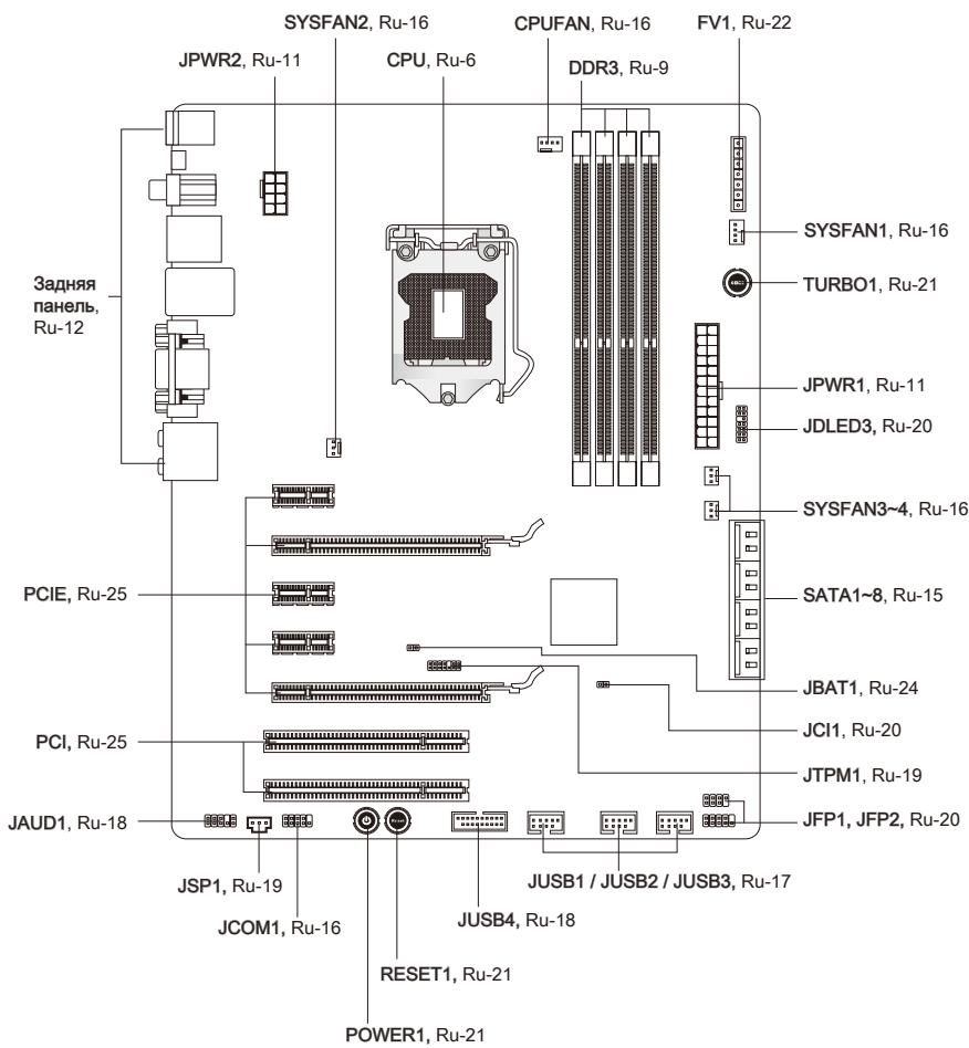
Quick Components Guide
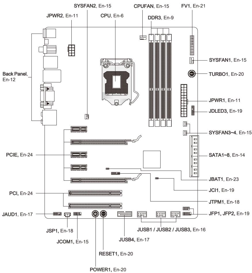
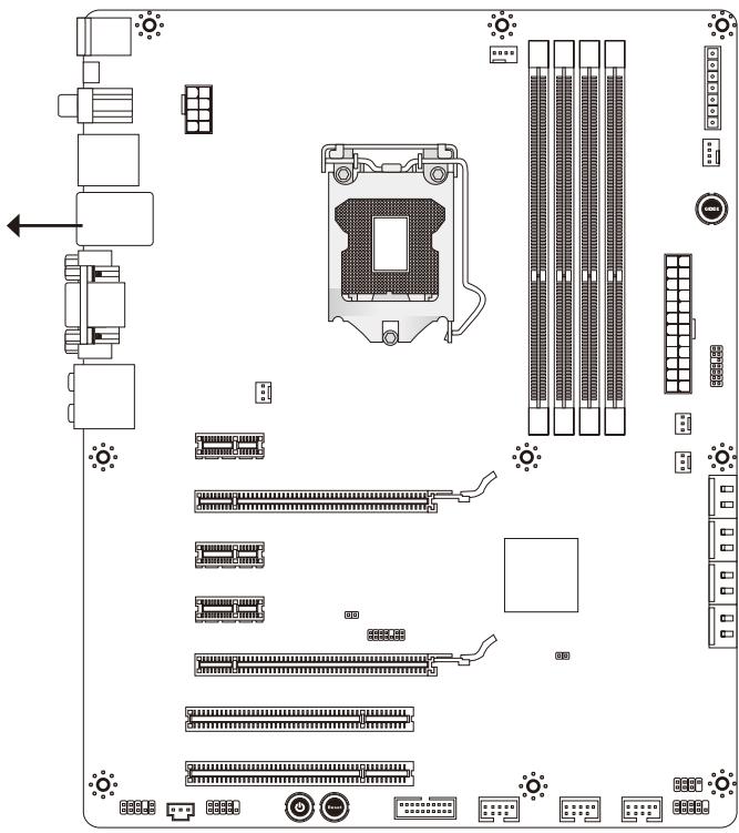
Screw Holes
When you install the mainboard, you have to place the mainboard into the chassis in the correct direction. The locations of screws holes on the mainboard are shown as below.
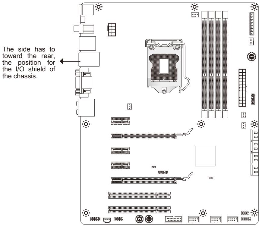

Refer above picture to install standoffs in the appropriate locations on chassis and then screw through the mainboard screw holes into the standoffs.
Important
- To prevent damage to the mainboard, any contact between the mainboard circuit and chassis or unnecessary standoffs mounted on the chassis is prohibited.
- Please make sure there are no metal components placed on the mainboard or within the chassis that may cause short circuit of the mainboard.
CPU (Central Processing Unit)
When you are installing the CPU, make sure to install the cooler to prevent overheating. If you do not have the CPU cooler, consult your dealer before turning on the computer.
For the latest information about CPU, please visit
0http://www.msi.com/service/cpu-support
Important
Overheating
Overheating will seriously damage the CPU and system. Always make sure the cooling fan can work properly to protect the CPU from overheating. Make sure that you apply an even layer of thermal paste (or thermal tape) between the CPU and the heatsink to enhance heat dissipation.
Replacing the CPU
While replacing the CPU, always turn off the ATX power supply or unplug the power supply's power cord from the grounded outlet first to ensure the safety of CPU.
Overclocking
This mainboard is designed to support overclocking. However, please make sure your components are able to tolerate such abnormal setting, while doing overclocking. Any attempt to operate beyond product specifications is not recommended. We do not guarantee the damages or risks caused by inadequate operation or beyond product specifications.
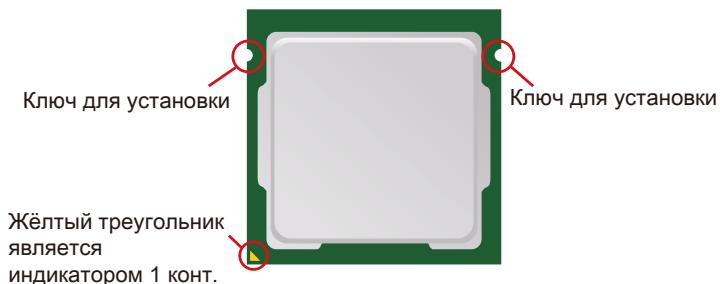
Introduction to LGA 1155 CPU
The surface of LGA 1155 CPU. Remember to apply some thermal paste on it for better heat dispersion.
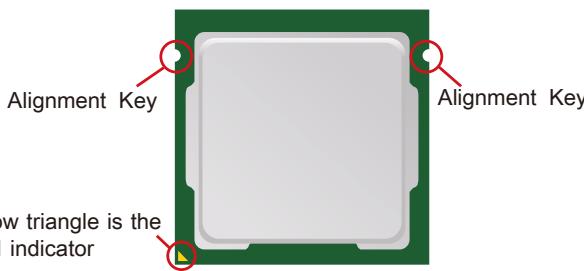
Yellow triangle is the
Pin 1 indicator
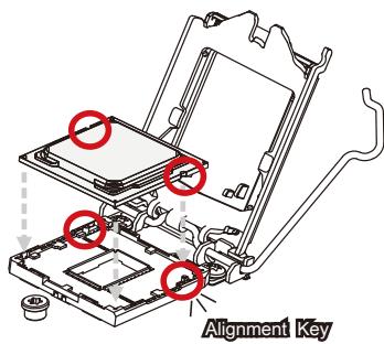
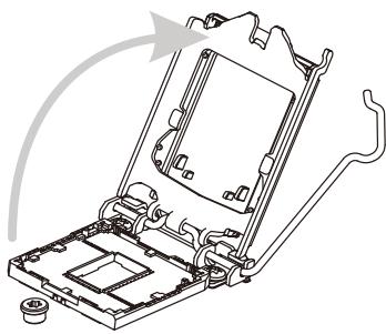
CPU & Cooler Installation
When you are installing the CPU, make sure the CPU has a cooler attached on the top to prevent overheating. Meanwhile, do not forget to apply some thermal paste on CPU before installing the heat sink/cooler fan for better heat dispersion.
Follow the steps below to install the CPU & cooler correctly. Wrong installation will cause the damage of your CPU & mainboard.
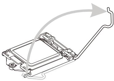
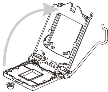
- Open the load lever.

- After confirming the CPU direction for correct mating, put down the CPU in the socket housing frame. Be sure to grasp on the edge of the CPU base. Note that the alignment keys are matched.
- Lift the load lever up to fully open position.
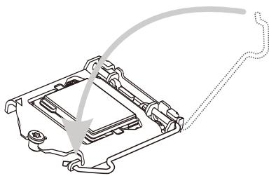
- Remove the plastic cap. Engage the load lever while pressing down lightly onto the load plate.
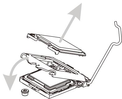
Important
Visually inspect if the CPU is seated well into the socket. If not, take out the CPU with pure vertical motion and reinstall.
- Secure the lever near the hook end under the retention tab.

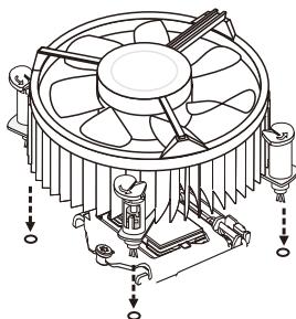
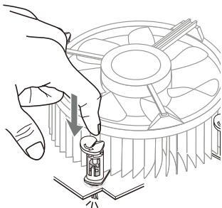
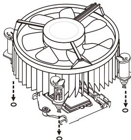
- Press the four hooks down to fasten the cooler. Turn over the mainboard to confirm that the clip-ends are correctly inserted.
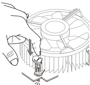
- Make sure the four hooks are in proper position before you install the cooler. Align the holes on the mainboard with the cooler. Push down the cooler until its four clips get wedged into the holes of the mainboard.
- Finally, attach the CPU Fan cable to the CPU fan connector on the mainboard.
Important
- Confirm if your CPU cooler is firmly installed before turning on your system.
- Do not touch the CPU socket pins to avoid damaging.
- Whenever CPU is not installed, always protect your CPU socket pin with the plastic cap covered to avoid damaging.
- Please refer to the documentation in the CPU cooler package for more details about the CPU cooler installation.
- Read the CPU status in BIOS.
Memory
These DIMM slots are used for installing memory modules. For more information on compatible components, please visit http://www.msi.com/service/test-report
DDR3
240-pin, 1.5V

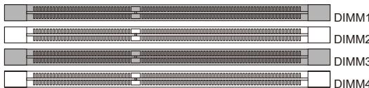
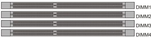
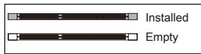
Dual-Channel mode Population Rule
In Dual-Channel mode, the memory modules can transmit and receive data with two data bus lines simultaneously. Enabling Dual-Channel mode can enhance the system performance. The following illustrations explain the population rules for Dual-Channel mode.
①
(2)
Important
- DDR3 memory modules are not interchangeable with DDR2, and the DDR3 standard is not backwards compatible. You should always install DDR3 memory modules in the DDR3 DIMM slots.
- In Dual-Channel mode, make sure that you install memory modules of the same type and density in different channel DIMM slots.
- To ensure a successful system boot-up, always insert the memory modules into the DIMM1 first.
- Due to the chipset resource deployment, the system density will only be detected up to 31+GB (not full 32GB) when each DIMM is installed with a 8GB memory module.
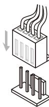
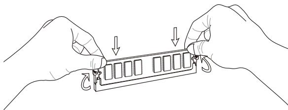
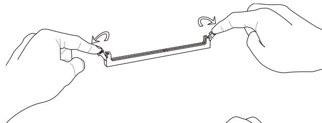
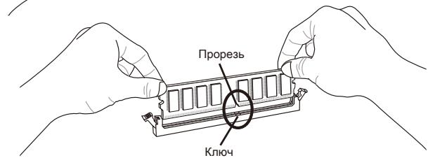
Installing Memory Modules
- The memory module has only one notch on the center and will only fit in the right orientation.
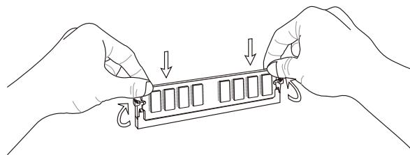
- Insert the memory module vertically into the DIMM slot. Then push it in until the golden finger on the memory module is deeply inserted in the DIMM slot. The plastic clip at each side of the DIMM slot will automatically close when the memory module is properly seated.
- Manually check if the memory module has been locked in place by the DIMM slot clips at the sides.


Important
You can barely see the golden finger if the memory module is properly inserted in the DIMM slot.
Power Supply
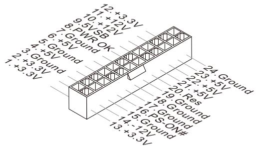
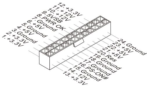
ATX 24-pin Power Connector: JPWR1
This connector allows you to connect an ATX 24-pin power supply. To connect the ATX 24-pin power supply, make sure the plug of the power supply is inserted in the proper orientation and the pins are aligned. Then push down the power supply firmly into the connector.
You may use the 20-pin ATX power supply as you like. If you'd like to use the 20-pin ATX power supply, please plug your power supply along with pin 1 & pin 13.
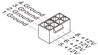
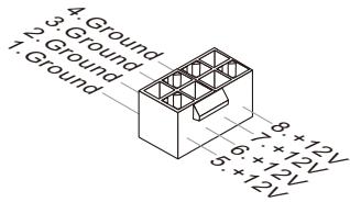
ATX 8-pin Power Connector: JPWR2
This connector is used to provide the power output to the CPU.
Important
Make sure that all the connectors are connected to proper ATX power supplies to ensure stable operation of the mainboard.
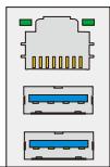
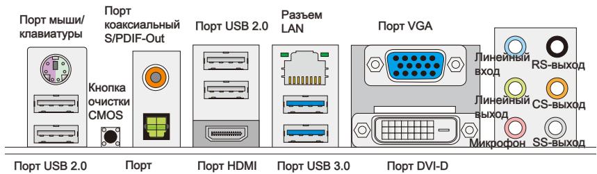
Back Panel
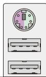
Keyboard/ Mouse
Coaxial S/PDIF-Out

USB 2.0 Port
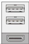
LAN
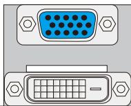
VGA Port
USB 2.0 Port
Optical S/PDF Port
HDMI Port
USB 3.0 Port
DVI-D Port
Mouse/Keyboard
The standard PS/2® mouse/keyboard DIN connector is for a PS/2® mouse/keyboard.
USB 2.0 Port
The USB (Universal Serial Bus) port is for attaching USB devices such as keyboard, mouse, or other USB-compatible devices.
USB 3.0 Port
USB 3.0 port is backward-compatible with USB 2.0 devices. Supports data transfer rate up to 5 Gbit/s (SuperSpeed).
Important
If you want to use a USB 3.0 device, you must use the USB 3.0 cable to connect to the USB 3.0 port.
Clear CMOS Button
There is a CMOS RAM on board that has a power supply from external battery to keep the system configuration data. With the CMOS RAM, the system can automatically boot OS every time it is turned on. If you want to clear the system configuration, use the button to clear data. Press the button to clear the data.
Important
-
Make sure that you power off the system before clearing CMOS data.
-
After pressing this button to clear CMOS data in power off (G3) state, the system will boot automatically.
Coaxial S/PDIF-Out
This SPDIF (Sony & Philips Digital Interconnect Format) connector is provided for digital audio transmission to external speakers through a coaxial cable.
Optical S/PDIF-Out
This S/PDIF (Sony & Philips Digital Interconnect Format) connector is provided for digital audio transmission to external speakers through an optical fiber cable.
HDMI Port
The High-Definition Multimedia Interface (HDMI) is an all-digital audio/video interface capable of transmitting uncompressed streams. HDMI supports all TV format, including standard, enhanced, or high-definition video, plus multi-channel digital audio on a single cable.
VGA Port
The DB15-pin female connector is provided for monitor.
DVI-D Port
The DVI-D (Digital Visual Interface-Digital) connector allows you to connect a LCD monitor. It provides a high-speed digital interconnection between the computer and its display device. To connect an LCD monitor, simply plug your monitor cable into the DVI-D connector, and make sure that the other end of the cable is properly connected to your monitor (refer to your monitor manual for more information).
Important
The HDMI, VGA and DVI-D ports on the mainboard are designed to serve as IGP (Integrated Graphics Processor) used. If you installed a processor without integrated graphics chip, these display ports will have no effect.
LAN
The standard RJ-45 LAN jack is for connection to Yellow Green/Orange the Local Area Network (LAN). You can connect a network cable to it.
| LED | Color | LED State | Condition |
| Left | Yellow | Off | LAN link is not established. |
| On(Steady state) | LAN link is established. | ||
| On(brighter & pulsing) | The computer is communicating with another computer on the LAN. | ||
| Right | Green | Off | 10 Mbits/sec data rate is selected. |
| On | 100 Mbits/sec data rate is selected. | ||
| Orange | On | 1000 Mbits/sec data rate is selected. |
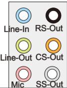
Audio Ports
These audio connectors are used for audio devices. It is easy to differentiate between audio effects according to the color of audio jacks.
Line-In: Blue - Line In, is used for external CD player, tape-player or other audio devices.
Line-Out: Green - Line Out, is a connector for speakers or headphones.
- Mic: Pink - Mic, is a connector for microphones.
RS-Out: Black - Rear-Surround Out in 4/5.1/7.1 channel mode.
CS-Out: Orange - Center/ Subwoofer Out in 5.1/7.1 channel mode.
SS-Out: Gray - Side-Surround Out in 7.1 channel mode.
Connectors
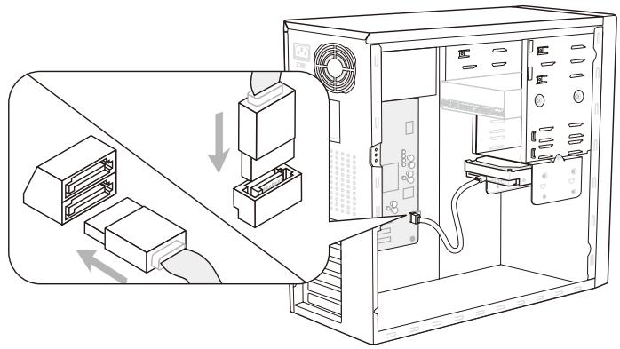
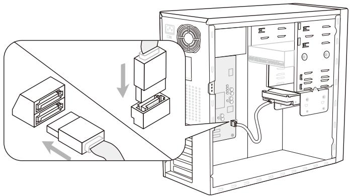
Serial ATA Connector: SATA1~8
This connector is a high-speed Serial ATA interface port. Each connector can connect to one Serial ATA device.
* The MB layout in this figure is for reference only.
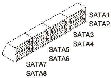
SATA1~2 (6Gb/s)
supported by Intel® Z68
SATA3~6 (3Gb/s)
supported by Intel® Z68
SATA7~8 (6Gb/s)
supported by Marvell® 9128 (optional)
Important
Please do not fold the Serial ATA cable into 90-degree angle. Otherwise, data loss may occur during transmission.
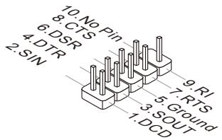
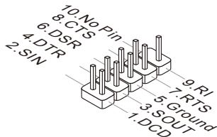
Serial Port Connector: JCOM1
This connector is a 16550A high speed communication port that sends/receives 16 bytes FIFOs. You can attach a serial device.
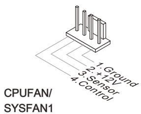
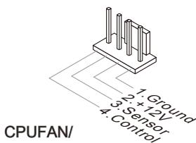
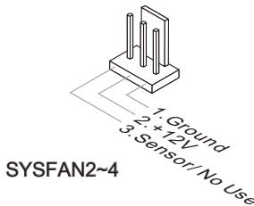
Fan Power Connectors: CPUFAN,SYSFAN1\~4
The fan power connectors support system cooling fan with +12V . When connecting the wire to the connectors, always note that the red wire is the positive and should be connected to the +12V ; the black wire is Ground and should be connected to GND. If the mainboard has a System Hardware Monitor chipset on-board, you must use a specially designed fan with speed sensor to take advantage of the CPU fan control.
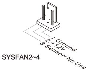
Important
- Please refer to the recommended CPU fans at processor's official website or consult the vendors for proper CPU cooling fan.
- CPUFAN, SYSFAN1 support Smart fan control. You can install Control Center utility that will automatically control the fan speeds according to the actual temperatures.
Fan cooler set with 3 or 4 pins power connector are both available for CPUFAN and SYSFAN1.
Front USB Connector: JUSB1 / JUSB2 / JUSB3
This connector, compliant with Intel® I/O Connectivity Design Guide, is ideal for connecting high-speed USB interface peripherals such as USB HDD, digital cameras, MP3 players, printers, modems and the like.
The JUSB1 (red mark) supports the MSI newly Super-Charger technology which provides fast charging function anytime for charging your Smartphone.
If your system is in S0 / S1 state, you must install MSI's application, SuperCharger, to control the JUSB1. When the application is set to "On", it can fast charge Smartphone via JUSB1 but the data transmission and synchronization will be disabled. When the application is set to "Off", the JUSB1 will work as a normal USB connector. In S3 / S4 / S5 state, JUSB1 can still provide fast charging function without operating system, no matter you un-plug and re-plug the Smartphone.
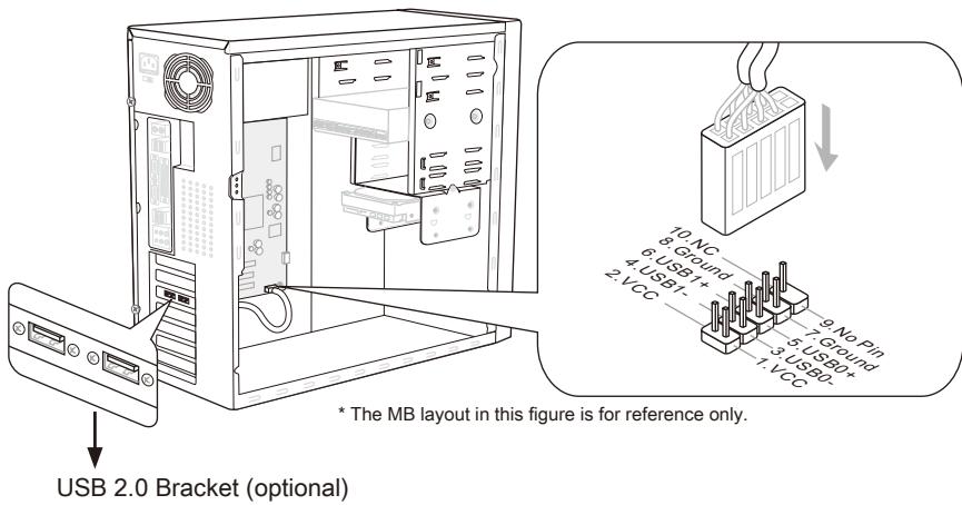
Important
- Note that the pins of VCC and GND must be connected correctly to avoid possible damage.
- For iPad, JUSB1 (red mark) can still charge iPad in S3, S4, S5 state.
- Please note that connecting one device once for stable charging is recommended.
- Super-Charger technology would be available on specific models, please refer to MSI website for model support list.
- We recommend that don't disconnect the device when you charge it in S1 state.
Front USB Connector: JUSB4
USB 3.0 port is backward-compatible with USB 2.0 devices. Supports data transfer rate up to 5 Gbit/s (SuperSpeed).
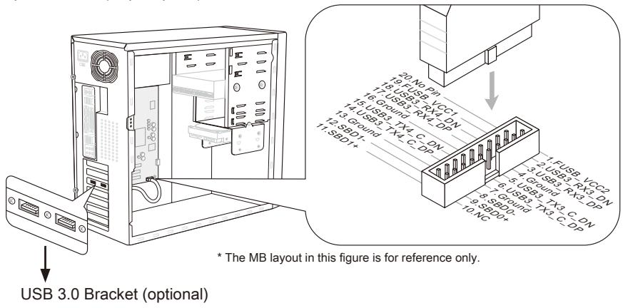
Important
- Note that the pins of VCC and GND must be connected correctly to avoid possible damage.
- If you want to use a USB 3.0 device, you must use the USB 3.0 cable to connect to the USB 3.0 port.
Front Panel Audio Connector: JAUD1
This connector allows you to connect the front panel audio and is compliant with Intel® Front Panel I/O Connectivity Design Guide.

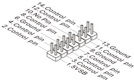
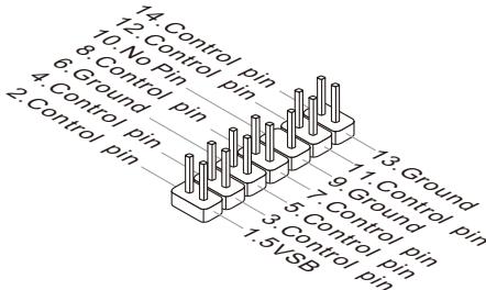
TPM Module connector: JTPM1
This connector connects to a TPM (Trusted Platform Module) module (optional). Please refer to the TPM security platform manual for more details and usages.
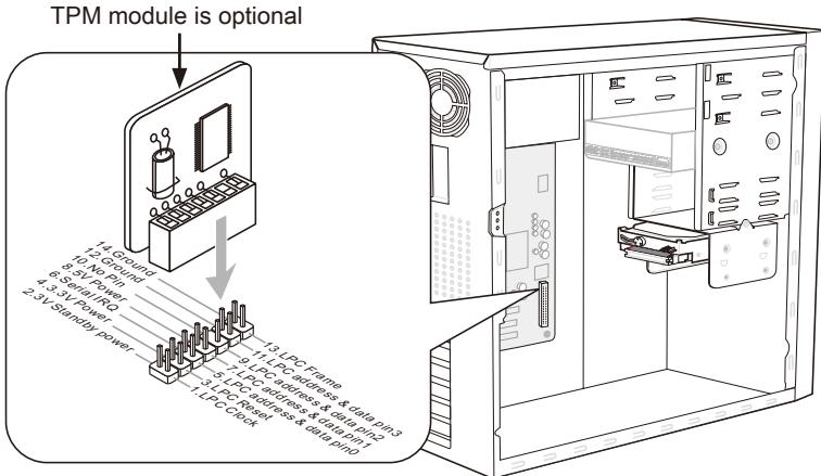
* The MB layout in this figure is for reference only.
S/PDIF-Out Connector: JSP1
This connector is used to connect S/PDIF (Sony & Philips Digital Interconnect Format) interface for digital audio transmission.
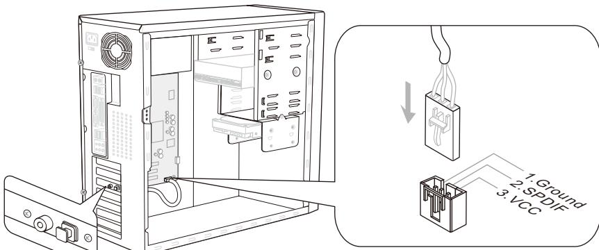
* The MB layout in this figure is for reference only.
S/PDIF-Out Bracket (optional)
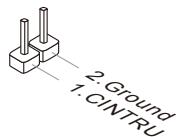
Chassis Intrusion Connector: JCI1
This connector connects to the chassis intrusion switch cable. If the chassis is opened, the chassis intrusion mechanism will be activated. The system will record this status and show a warning message on the screen. To clear the warning, you must enter the BIOS utility and clear the record.
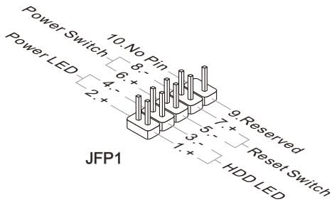
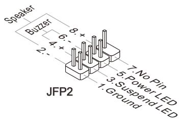
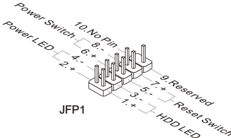
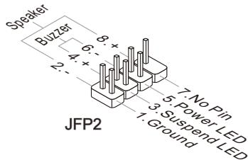
Front Panel Connectors: JFP1, JFP2
These connectors are for electrical connection to the front panel switches and LEDs. The JFP1 is compliant with Intel® Front Panel I/O Connectivity Design Guide.
DLED3 Connector:JDLED3 (optional)
This is reserved for connecting the MSI future control card.
Buttons
The mainboard provides the following buttons for you to set the computer's function. This section will explain how to change your mainboard's function through the use of button.
OC Genie Button: TURBO1
This button is used to auto-overclock for the system. Press this button to enable the OC Genie function when the system is in power off state, meanwhile, the button will light and lock. And then the system will automatically detect the optimum values to overclock after booting the system. To disable the OC Genie function, please press the button again after power off the system, meanwhile, the button light will off and unlock, and the system will restore the default for next boot.

Important
- Please install the DDR3 1333 and up memory and equip better heat sink/ cooler with OC Genie function.
- We do not guarantee the OC Genie overclocking range and the damages or risks caused by the OC Genie overclocking behavior.
- You can disable the OC Genie function in BIOS setup. And we suggest you to save the OC Genie configuration to overclocking profile in BIOS for future using.
Power Button: POWER1
This button is used to turn-on or turn-off the system. Press the button to turn-on or turn-off the system.

Reset Button: RESET1
This button is used to reset the system. Press the button to reset the system.

Voltage Check Point
Voltage Check Point: FV1
This voltage check point set is used to measure the current CPU/ CPU_VTT/ CPU_GFX/ DDR/ PCH voltage.
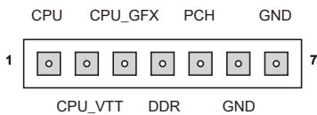
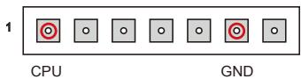
CPU voltage: measure the current CPU voltage with CPU point and GND point by using a multimeter.
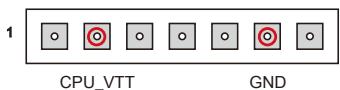
CPU_VTT voltage: measure the current CPU VTT voltage with CPU_VTT point and GND point by using a multimeter.
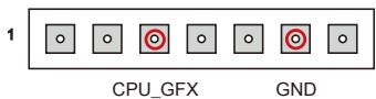
CPU_GFX voltage: measure the current CPU
7 Integrated Graphic voltage with CPU_GFX point and GND point by using a multimeter.
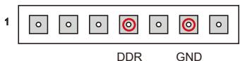
DDR voltage: measure the current DDR voltage with DDR point and GND point by using a multimeter.
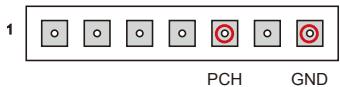
PCH voltage: measure the current PCH voltage with PCH point and GND point by using a multimeter.
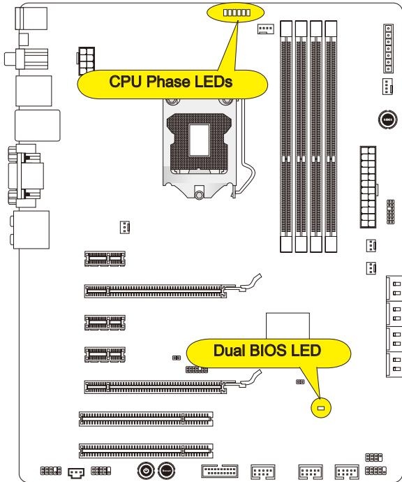
LED Status Indicators
CPU Phase LEDs
These LEDs indicate the current CPU power phase mode. Follow the instructions below to read.

Lights

Off
| CPU is in 1 phase power mode. | |
| CPU is in 2 phase power mode. | |
| CPU is in 3 phase power mode. | |
| CPU is in 4 phase power mode. | |
| CPU is in 5 phase power mode. | |
| CPU is in 6 phase power mode. |
Dual BIOS LED
The Dual BIOS LED indicates the BIOS status during system power on. Follow the instructions below to read.
Off: Normal.
Blink (1 cycle/second): The primary BIOS failed.
Solid: Both primary and secondary BIOS failed.
Jumper
Clear CMOS Jumper: JBAT1
There is a CMOS RAM onboard that has a power supply from an external battery to keep the data of system configuration. With the CMOS RAM, the system can automatically boot OS every time it is turned on. If you want to clear the system configuration, set the jumper to clear data.
JBAT1

Keep Data

Clear Data
Important
You can clear CMOS by shorting 1-2 pin while the system is off, then open it. Avoid clearing the CMOS while the system is on; it will damage the mainboard.
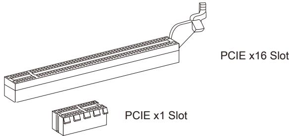
Slots
PCIE (Peripheral Component Interconnect Express) Slot
The PCIE slot supports the PCIE interface expansion card.
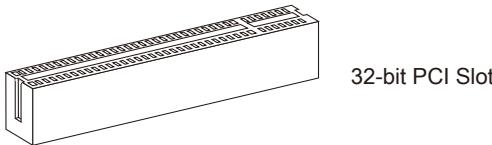
PCI (Peripheral Component Interconnect) Slot
The PCI slot supports LAN card, SCSI card, USB card, and other add-on cards that comply with PCI specifications.
Important
When adding or removing expansion cards, make sure that you unplug the power supply first. Meanwhile, read the documentation for the expansion card to configure any necessary hardware or software settings for the expansion card, such as jumpers, switches or BIOS configuration.
PCI Interrupt Request Routing
The IRQ, acronym of interrupt request line and pronounced I-R-Q, are hardware lines over which devices can send interrupt signals to the microprocessor. The PCI IRQ pins are typically connected to the PCI bus pins as follows:
| Order1 | Order2 | Order3 | Order4 | |
| PCI Slot1 | INT A# | INT B# | INT C# | INT D# |
| PCI Slot2 | INT B# | INT C# | INT D# | INT A# |
BIOS Setup
This chapter provides basic information on the BIOS Setup program and allows you to configure the system for optimum use. You may need to run the Setup program when:
- An error message appears on the screen during the system booting up, and requests you to run BIOS SETUP.
You want to change the default settings for customized features.
Important
- The items under each BIOS category described in this chapter are under continuous update for better system performance. Therefore, the description may be slightly different from the latest BIOS and should be held for reference only.
- Upon boot-up, the 1st line appearing after the memory count is the BIOS version. It is usually in the format:
E7681IMS.xxx 052011 where:
1st digit refers to BIOS type as E = EFI
2nd - 5th digit refers to the model number.
6th digit refers to the chipset as I = Intel, N = n Vidia, A = AMD and V = VIA .
7th - 8th digit refers to the customer as MS = all standard customers.
xxx refers to the BIOS version.
052011 refers to the date this BIOS was released.
Entering Setup
Power on the computer and the system will start POST (Power On Self Test) process. When the message below appears on the screen, press key to enter Setup.
Press DEL to enter Setup Menu, F11 to enter Boot Menu
If the message disappears before you respond and you still wish to enter Setup, restart the system by turning it OFF and On or pressing the RESET button. You may also restart the system by simultaneously pressing <Ctrl> , <Alt> , and <Delete> keys.
Control
| Keyboard | Mouse | Description |
| <↑ ↓> | Move the cursor | Select Item |
| <Enter> | Click/ Double-click the left button | Select Icon/ Field |
| <Esc> | Click the right button | Jumps to the Exit menu or returns to the previous from a submenu |
| <++> | Decrease the numeric value or make changes | |
| <-> | ||
| <F1> | General Help | |
| <F4> | CPU Specifications | |
| <F5> | Enter Memory-Z | |
| <F6> | Load optimized defaults | |
| <F10> | Save Change and Reset | |
| <Esc> | Exit | |
Sub-Menu
If you find a right pointer symbol (as shown in the right view) appears to the left of certain fields that means a sub-menu can be launched from this field. A sub-menu contains additional options for a field parameter. You can use arrow keys ( ) or mouse to highlight the field and
PCI Subsystem Settings
ACPI Settings
Integrated Peripherals
On-Chip VGA Devices
press
The BIOS setup program provides a General Help screen. You can call up this screen from any menu by simply pressing
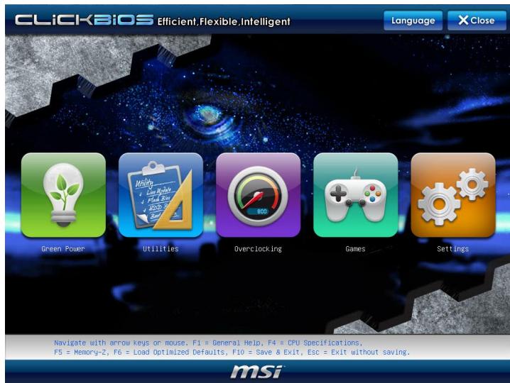
The Main Menu
Once you enter BIOS CMOS Setup Utility, the Main Menu will appear on the screen. The Main Menu allows you to select from the setup functions.

Language
After entering the Setup menu, you can see a "Language" button. Please click it and select the language, at your desire, for the BIOS setting first.
Green Power
Click "Green Power" icon to enter the menu. Use this menu to specify the power phase.
Utilities
Click "Utilities" icon to enter the menu. This menu provides the useful utility for you to live update bios and hard disk backup.
Overclocking
Click "Overclocking" icon to enter the menu. Use this menu to specify your settings for frequency/voltage control and overclocking.
Games
Click "Games" icon to enter the menu. This menu provides several games for you to play.
Settings
Click "Settings" icon to enter the menu. Use this menu to specify your settings for chipset features, boot device and password.
When enter the BIOS Setup utility, follow the processes below for general use.
- Load Optimized Defaults: Select [Settings] -> [Save & Exit] -> [Restore Defaults] and click on it. And then the screen shows a pop-up message as below. Select [Yes] and click on it to load the default settings for optimal system performance.

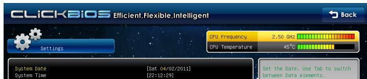
- Setup Date/ Time: Select [Settings] -> [System Status] -> [System Date]/ [System Time] and click on it. And then, you can key-in the Date, Time in their respective fields.
- Save & Exit Setup: Select [Settings] -> [Save & Exit] -> [Save Changes and Reboot] and click on it. And then the screen shows a pop-up message as below. Select [Yes] and click on it to save the configurations and exit BIOS setup utility.

- OC Menu Introduction : This menu is for advanced user who want to overclock the mainboard.
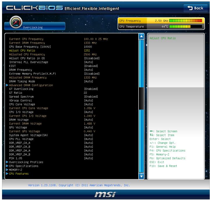
Current CPU / DRAM Frequency
These items show the current clocks of CPU and Memory speed. Read-only.
CPU Base Frequency [10KHz]
This item allows you to set the CPU Base clock (in 10KHz). You may overclock the CPU by adjusting this value. Please note the overclocking behavior is not guaranteed.
Adjust CPU Ratio
This item controls the multiplier that is used to determine the internal clock speed of the processor relative to the external or motherboard clock speed. It is available only when the processor supports this function.
Adjusted CPU Frequency
It shows the adjusted CPU frequency. Read-only.
Adjust CPU Ratio in OS
Enable this item, it will allow you to change the CPU ratio in OS by using MSI application.
Internal PLL Overvoltage
This item are used to adjust the PLL voltage.
EIST
The Enhanced Intel SpeedStep technology allows you to set the performance level of the microprocessor whether the computer is running on battery or AC power. This field will appear after you installed the CPU which supports speedstep technology.
DRAM Frequency
This setting controls the frequency of memory.
Extreme Memory Profile(X.M.P)
This item is used to enable/disable the Intel Extreme Memory Profile (XMP). For further information please refer to Intel's official website.
Adjusted DRAM Frequency
It shows the adjusted DRAM frequency. Read-only.
DRAM Timing Mode
Select whether DRAM timing is controlled by the SPD (Serial Presence Detect) EEPROM on the DRAM module. Setting to [Auto] enables DRAM timings and the following "Advanced DRAM Configuration" sub-menu to be determined by BIOS based on the configurations on the SPD. Selecting [Link] or [Unlink] allows users to configure the DRAM timings and the following related "Advanced DRAM Configuration" sub-menu manually.
Advanced DRAM Configuration
Press
Command Rate2
This setting controls the DRAM command rate.
tCL
This controls the CAS latency, which determines the timing delay (in clock cycles) before SDRAM starts a read command after receiving it.
tRCD
When DRAM is refreshed, both rows and columns are addressed separately. This setup item allows you to determine the timing of the transition from RAS (row address strobe) to CAS (column address strobe). The less the clock cycles, the faster the DRAM performance.
tRP
This setting controls the number of cycles for Row Address Strobe (RAS) to be allowed to precharge. If insufficient time is allowed for the RAS to accumulate its charge before DRAM refresh, refreshing may be incomplete and DRAM may fail to retain data. This item applies only when synchronous DRAM is installed in the system.
tRAS
This setting determines the time RAS takes to read from and write to memory cell.
tRFC
This setting determines the time RFC takes to read from and write to a memory cell.
tWR
Minimum time interval between end of write data burst and the start of a precharge
command. Allows sense amplifiers to restore data to cells.
-tWTR
Minimum time interval between the end of write data burst and the start of a column-read command. It allows I/O gating to overdrive sense amplifiers before read command starts.
tRRD
Specifies the active-to-active delay of different banks.
tRTP
Time interval between a read and a precharge command.
tFAW
This item is used to set the tFAW (four activate window delay) timing.
tWCL
This item is used to set the tWCL (Write CAS Latency) timing.
tCKE
This item is used to set the tCKE timing.
Advanced Channel 1/2 Timing Configuration
Press
- tRRDR/tRRDD/tWWDR/tWWDD/tRWRDD/tWRDRDD/tRWSR
These items is used to set the memory timings for memory channel 1/2.
>GT OverClocking
This item allows you to enable/ disable the overclocking of integrated graphics.
GT Ratio
This setting controls the ratio of integrated graphics frequency to enable the integrated graphics to run at different frequency combinations.
Spread Spectrum
When the mainboard's clock generator pulses, the extreme values (spikes) of the pulses create EMI (Electromagnetic Interference). The Spread Spectrum function reduces the EMI generated by modulating the pulses so that the spikes of the pulses are reduced to flatter curves.
Important
- If you do not have any EMI problem, leave the setting at [Disabled] for optimal system stability and performance. But if you are plagued by EMI, select the value of Spread Spectrum for EMI reduction.
- The greater the Spread Spectrum value is, the greater the EMI is reduced, and the system will become less stable. For the most suitable Spread Spectrum value, please consult your local EMI regulation.
- Remember to disable Spread Spectrum if you are overclocking because even a slight jitter can introduce a temporary boost in clock speed which may just cause your overclocked processor to lock up.
VDroop Control
This item is used to select the VDroop control mode.
CPU Core Voltage/ CPU I/O Voltage/ DRAM Voltage/ GPU Voltage/ System Agent Voltage(SA)/CPU PLL Voltage/DDR_VREF_CA_A/DDR_VREF_CA_B/DDR_VREF_DA_A/DDR_VREF_DA_B/PCH 1.05
These items are used to adjust the voltage of CPU, Memory and chipset.
- Current CPU Core Voltage/ Current CPU I/O Voltage/ Current DRAM Voltage/ Current GPU Voltage
These items show current CPU Core/ CPU I/O/ DRAM/ GPU voltage. Read-only.
Overclocking Profiles
Press
Overclocking Profile 1/2/3/4/5/6
Press
OC Retry Count
When overclocking has failed, setting this item as [1, 3] will allow system to reboot 1/3 times with the same overclocked configuration. If overclocking has failed every time, the system will restore the defaults.
CPU Specifications
Press
CPU Technology Support
Press
MEMORY-Z
Press
DIMM1~4 Memory SPD
Press
X.M.P Support Information
Press
CPU Features
Press
Hyper-threading
The processor uses Hyper-Threading technology to increase transaction rates and reduces end-user response times. The technology treats the two cores inside the processor as two logical processors that can execute instructions simultaneously. In this way, the system performance is highly improved. If you disable the function, the processor will use only one core to execute the instructions. Please disable this item if your operating system doesn't support HT Function, or unreliability and instability may occur.
Important
Enabling the functionality of Hyper-Threading Technology for your computer system requires ALL of the following platform Components:
CPU: An Intel® Processor with HT Technology;
- Chipset: An Intel® Chipset that supports HT Technology;
- BIOS: A BIOS that supports HT Technology and has it enabled;
- OS: An operating system that supports HT Technology.
For more information on Hyper-threading Technology, go to:
http://www.intel.com/technology/platform-technology/hyper-threading/
Active Processor Cores
This item allows you to select the number of active processor cores.
Limit CPUID Maximum
It is designed to limit the listed speed of the processor to older operating systems.
Execute Disable Bit
Intel's Execute Disable Bit functionality can prevent certain classes of malicious "buffer overflow" attacks when combined with a supporting operating system. This functionality allows the processor to classify areas in memory by where application code can execute and where it cannot. When a malicious worm attempts to insert code in the buffer, the processor disables code execution, preventing damage or worm propagation.
Intel Virtualization Tech
This item is used to enable/disable the Intel Virtualization technology. For further information please refer to Intel's official website.
Intel VT-D Tech
This item is used to enable/disable the Intel VT-D technology. For further information please refer to Intel's official website.
Power Technology
This item allows you to select the Intel Dynamic Power technology mode.
C1E Support
To enable this item to read the CPU power consumption while idle. Not all processors support Enhanced Halt state (C1E).
OverSpeed Protection
Overspeed Protection function can monitor the current CPU draws as well as its power consumption. If it exceeds a certain level, the processor automatically reduces its clock speed. If you want to overclock your CPU, set it to [Disabled].
Intel C-State
C-state is a power management state that significantly reduces the power of the processor during idle. This field will appear after you installed the CPU which supports c-state technology.
Package C-State limit
This feild allows you to select a C-state mode.
Long duration power limit(W)
This field allows you to adjust the TDP limit for the long duration.
Long duration maintained(ms)
This field allows you to adjust the maintaining time for long duration power limit.
Short duration power limit(W)
This field allows you to adjust the TDP limit for the short duration.
Primary plane turbo power limit(W)
This field allows you to adjust the TDP limit for the primary plane turbo.
Software Information
Take out the Driver/Utility DVD that is included in the mainboard package, and place it into the DVD-ROM drive. The installation will auto-run, simply click the driver or utility and follow the pop-up screen to complete the installation. The Driver/Utility DVD contains the:
- Driver menu : It provides available drivers. Install the driver by your desire and to activate the device.
- Utility menu : It allows you to install the available software applications.
- Service base menu : Through this menu to link the MSI officially website.
- Product info menu : It shows the newly information of MSI product.
- Security menu : It provides the useful antivirus program.
Important
Please visit the MSI officially website to get the latest drivers and BIOS for better system performance.

Deutsch
Z68A-GD65 (B3)/
Z68A-GD55 (B3)
Serie
Spezifikationen
Prozessoren
4 SATA 6Gb/s Anschlüsse
Frontpanel Anschlüsse: JFP1, JFP2
PCI Subsystem Settings
ACPI Settings
Integrated Peripherals
On-Chip VGA Devices
Current CPU / DRAM Frequency
CPU Base Frequency [10KHz]
Adjusted CPU Frequency
Adjust CPU Ratio in OS
Adjusted DRAM Frequency
Advanced Channel 1/2 Timing Configuration
CPU Technology Support
http://www.intel.com/technology/platform-technology/hyper-threading/
Intel Virtualization Tech
OverSpeed Protection
Package C-State limit
> Long duration maintained(ms)
Primary/ Secondary plane turbo power limit (W)
http://www.msi.com/service/cpu-support
Important
Surchauffe
Emplacement PCIE (Peripheral Component Interconnect Express)
Emplacement PCI (Peripheral Component Interconnect)
Current CPU / DRAM Frequency
CPU Base Frequency [10KHz]
Adjusted CPU Frequency
Adjust CPU Ratio in OS
Adjusted DRAM Frequency
Advanced Channel 1/2 Timing Configuration
CPU Technology Support
http://www.intel.com/technology/platform-technology/hyper-threading/
Intel Virtualization Tech
OverSpeed Protection
Long duration maintained(ms)
Pa3MeueHne KOMNoHEtOB CnCTeMHoI PJIaTbI
OTBepCTnIy BnHTOB
Ipn yctaHOBKe cncTeHMHO nnTaBt HxKHO BCTaBnTb eB B KOpNc B npaBnJbHOM HanpaBnEHH. Pa3MeueHnA OTBepCtn dIy BNHTOB NOKa3AHnKe.
Бokobbie CTOpOHb CneJyET npOTNB 3aJHero Koprnya, paMaMeuCheNe InI npoteKToPa BxOJa/ BbIXOJa Koprnya.

→ OТьерстядя ВИНTOB
CneyuTe yka3aHnM BblIe yka3aHHo Iy TaHOBKn DePkaTeJIeB NpabINbHOM MeCTe B Kopnyce n 3aTeM BBInHTte BInTbI Chepe3 OTBepCTNЯ dIra BInTOB B DePkaTeJI.
Bhuvahine
Bo n36eKaHne nobpeKdEHH K cNCTeMHoI pNaTe, IIObO KoNTaKT MeJy npOBoDkaMn CnCTeMHoI pNaTbI N KopnycOM uN HeO8aTeIbHbI DePkaTeIb yCTaHOBJIeH B Kopnyce 3anpeSeH.
- Y6eIntecb B TOM, UTO Ha CnCTeMHoN Pnate H Nn B Kopnyce HeT HnKaKOrO MetaIIuYeCKOrO KOMIOHeHTa, KOtOpBIM MOKeT Bbl3BaTb 3aKOpaYHbAHne CnCTeMHoN Pnate.
CPU (LêntpaJbHbI npoceccop)
Pn yctaHOBKe CPU, uTo6bI y6peey npoueessop ot neperpeBa, He 3a6yDbTe yCTaHOBt npoueessopbI Kyep. EcnIy Bac HET npoueessopHoro KUepa, noJkaIyIcTa, CBxKITecb C dInepom C cIeIbIO npio6peTeHn I erO yCTaHOBKn Do TORO, KaK BkIIOuHTe KOMNbOTep.
Последно Информацио о подержкп рpoцesscopob можно пolyntь на са即时 0http://www.msi.com/service/cpu-support
BHTMAHHE
IpeperpeB
Peperepe MoKet cepb3no NOBpeDnT bceHtpaIbHbI npOeCopp. UTo6bl ybepeb npOeCCOP OT nepepeBa, y6eINTecb B TOM, uTO npOeCCOPHbI Kynep paBoTaET HopMaIbHO.IIpyUyUWeHnA TEnNOoTBOd HneOBxOdmOHaNECTNCIOI TENNoPobOdaJe nactb (IIIN TENNoPobOdaJueN IeHTb) Mekdy npOeCCopOM IpaDnATOpOM.
3aMeHa CPU
Pn3aMeHe CPU, BO n36eXaHne ero nobpeXdHnra, o63aTeIbHo OTKIIouHTe NCTOuHnK nITaHnN IIN BbIhTe BuNkY bLOka nITaHnN 13 po3ETKn.
Pa3roH
3Ta cnCTemHna Pnata NaDpeKnBaet pa3roH. Y6eNTecb, yTO KOMNHeTbI CNCTembl CnOc6hbl pa6oTaB T Taknx HectaHdapThbIX pexImax npn pa3roHe. H peKomeHdyETcN CnOJIb30BaTb PnoyKT B pexImax, He COOTBeTcTByUx yKa3aHHbIM B cNeuΦnKaunx. Mbl He rapaHTnpyEm 3aunTy OT nobpeXdeHn n pncOB, BbI3BaHHbIX HeppaBnBHOJ 3KcIIpyaTaeH n UCTaHOBKO napameTPOB C npebblueHm XapaKTePNCtIK.
YctaHOBka npoceccopa LGA 1155
BheuHn Bn npoecoppa. YTo6bI yBeJIuHTb TeNlopaccenBaHne, y6eIntcB TOM, YTO HaHecen CIOI TeNlONpOBOJaue nactbl.
YctaHOBka npoceccopa n BENTNJIATOPA
Bo n36ekahne neperpeba npa pabote o6ra3atebho yctahOBHTe BHTnIaTOp npoecccopa. Ondobpemehno, yTO6bI yJyUHNTb TeNIOOTBOD, y6eINTEcB TOM, yTO HAnecEHN CNoI TeNlnonpoBODAuJe NaCTbHa npOceCCope nepeD yCTAHOBKOB BeHTnIaTopa.
CneyuTe daHbIM yka3aHnM dIy npabInbHO yCTaHOKn. HenpaBnBnaY cTaHOBA npBeDeT K NOBpeKdEnIO pOceccopa n CnCTeMHo INaTbI.
- Notarynte 3a pbyar kpenneHna.
- Y6eDnBwncb B npaBnJIbHOJ opneHTaun npoceccopa, nOToKInTe npoceccop B pa3beM. O6paTIne BHNMaHHe, yTO BbEMKn Ha npoceccope DOJXhbl COOTBeTCTBOBaTb BbICTyNam Ha npoceccopHom pa3beMe.

2.Понимпe рьчаги otКрочemeТаПИЧЕСКУОкышkyДлЯуctановкиnpoceccopa.
- Chmnte nactNKOByU kpbIuKy. Oynctnte MeTaJIHneCKyU KpbIuKy MexAHn3Ma KpeJIeHnJ.

BHIMAHWE
Bn3yabNo npoBepe Te npaBnIbHocTb yCTaHOBKn npOeCCopa B pa3bEm. EcnN npOeCCOP yCTaHOBNeH HenpaBnIbHO, TO bYbTe npOeCCOp n nepeyCTaHOBtE.
- Onyctnte pbIar Ha KpbIshky MexaHn3Ma KpenJIeHnI 3aФнксypIte erO.
- Haxmnte Ha yeTbpe 3aueJnKn 3akpenTe BEHTnJIaTOp. IpeBepHnTe cntemHyo nPaTy n y6eIInTeCb, YTO 3aueJNn NaedxHo ydepXnBaOT BeHTnJIaTOp.
- Перед установков В entnlaTopap y6eHntecb,чTO BCE yetbipe 3aueJIkn npabINbHO copneHTnpOBaHbI. COBmecTe NT OTBepCTNcCtEmHOI pNaTbC 3aueJIkAMK KpeJIeHnI B eHTnlaToppa. PnIXMmTE paDnATOp C BeHTnlaTOpOM K pOceCCopy IN pOscLeNTe, YTObUyETbPe 3aueJIkn BOJIM B O TBepCTNcCtEMHOI pNaTbI.
UcTaHOBKa MoDyIe NAmrTn
- Moулп памятп IMeOT Ondу npope3bВ cpeIeHneЧа'tn. Moуль boйдТВ pa3beM TOlbko pri npabuJIbHoI opHeNTaци.
- BCTaBbTe MoyIb B DIMM cNOT B BeptnKaJIbHOM HapBaJIeHm. 3aTEM haxMtte Ha Hero, yTo6bl 3oNoJeHBe KOHTaKbI rJy60KO nOrpy3uInncb B DIMM cnot. Ecnn MoyIb pAmrTn BCTaBJIeH npaBnJIbHO, To PnaCTnKOBbIe 3aUeJIKN Ha o6Ox KOnCuax 3aKpOHTcAB TOMaTnueckn.
- BpyuHny u6eHntecb, yTo moDyIb 3aKpeIenneB CcIote DIMM 3aUeJIkamn c o6eHX cTOpOH.
BHMaHne
30JIOJIe KOHTaKtI eEBA BnHbI, ecNI MOyIIN pAmrTn npABNJbHO pa3MeUeHbIB DIMCnote.
Pa3bem NHTaHn
24-KoHTaKTbIpa3bEmPiTaHnA TX:JPWR1
3TOT pa3bem NO3BONJET NOKNIHOnTb 24-KoHTaKTbI KOHKeTOp nITaHnA ATX. IJIra erO NOKJIIOUeHnY b6eINTEcB, YTO KOHKeTOp N KOHTaKTbI pa3bema IpaBUNbHO copHeHTnpOBaHbI. 3aTeM IIOTHO BCTaBbTe erO B pa3bem Ha CnCTEmHO nIaTe.
BbI TaKke MoKTe NcNoJIb3OBAtB 20-KoHTaKTHbIy ATX 6nok nTahnI. PpN IcNoJIb3OBAHmN 20-KoHTaKTHOro pa3beMa, NOdKJIouaYte erO BDoJI bKOHTaKToB 1 n 13.
8-KoHTaKTHbI pa3bem nHTaHnA TX: JPWR2
3TOT pa3bem nIITAHnI NCNOJIb3yETcI dIy o6ecneHEn IITaHnI pOuceccopa.
BhimaHae
Y6eIntecbB TOM,уTO BCE pa3beMbI NOkJIIOueHbIK NCTOCHKAM NITaHnA ATX dna CTaunbHOH pa60bI CNCTeMHo NNATbl.
3aHnaHeJIb
* KomnoentbI CnCTeMHOn IInaTbI B IN3o6paKeHN TOnBko DnIe CnpaBKn.
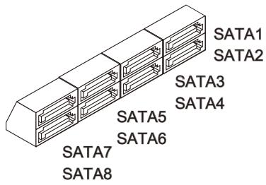
SATA1~2 (6Γ6/c)
pa6oTaIOT Ha YInCeTe Intel® Z68
SATA3~6 (3Γ6/c)
pa6oTaIOT Ha YInCeTe Intel® Z68
SATA7~8 (6Γ6/c)
pa6oTaIOT Ha YInCeTe Marvell 9128
(ONLMOHJIbHO)
BhimaHue
U36eraIte, noKanyIcTa, pe3Knx u3rN6OB ka6eIa Serial ATA. B npoTnBHom cnyae MOryT Bo3HnKHyTb nOtePn daHHbIX npi nepeDaue.
Pa3bem nocneioBaTeIbHoro npTa: JCOM1
JaHHb pa3bem YBnIeTcB BICOKOCKOcPcTHbIM NocJeIOBaTeNbHbIM NOPTom CBa3N 16550A c 16-6aItho npeDaueF FIFO. K 3tOMy pa3bemy MoXHO HeNoCpeIcTBeHNO NOkJIouHtB nocJeIOBaTeNbHo yCTpoIcTBO.
Pa3bem nIITaHnBEHTNIJIrTOpOB: CPUFAN,SYSFAN1\~4
Pa3bEmbl nHTaHnBEHTNlAToPob NOdEepKINBaOT BeHTNlAToPbI C nHTaHnEM +12B. PnnoDKJIIOUeHN Heo6XoJIMO NOMHNTb, YTO KpaChb I npOBOD noDKIIOUaETcK 5uHHe +12B, UepHb - K 3emne GND. Ecn H na CnCTeMHOn I pNaTe yctaHOBeHa MmKpocxema annapathoro MOHToPunHra, Heo6XoJIMO NcNoJIb3ObaTb CneuaJIbHbIe BEHTNlAToPbI c DaTHNKAMn CKOpOCTn Dnpeaun3aUnn FyHKUnynpabLeHnBEHTNlAToPamn.
SYSFAN1
BHMMAHNE
- 4To6bI y3HaTb O MOdEJIaX NOdXoJauNX BeHTnIaTOpOB, ObpaTntEcB, noKAnyIcTa, Ha oΦuNaJIbHbI Be6 caT nII npOKOHcyJIbTIpyuYTeCb C npOdaBcM.
- CPUFAN, SYSFAN1 noДержиВаHT ynpaВлЕнe CBOPOCТьв Враценя вERTИЯТОР. Дд abTOMATUcheKOrO KOHTPOnIa CBOPOCТи BERTИЯТОР npOcEccOpa, 3abNcAJIeN O T TeMпepaTpybl npoceccopa N CnCTeMbI, MoXHOb yctaHOBntb Control Center.
- Pa3bembl CPUFAN u SYSFAN1 nOДeprKnBaIOT BeHTnIaTOpbl, KaK c 3, TaK u c 4 KOHTaKTaMn.
KoHHeKToPbI nepeDneH nAHeN: JFP1, JFP2
ÖTN KOHNÉKTopbI NcOJIb3yUToTcДЯ NpOdKlHouEnH KHOJOK I INHdNkaTOpOB, paCnOLOXeHHbIX Ha nepeDnei nAHeNn Kopnyca. KoHNéKTop JFP1 coOTBeTCTByeT pyKOboVcTBy Intel® Front Panel I/O Connectivity Design.
Pa3bEM DLED3: JDLED3 (onuHaJIbHO)
3ToT pa3bem 3ape3epBnpoBaH dIy IIOdkNIOUeHn KOnTpOlbHoJ KapTbI MSI B6dyuem.
KhONK
Ha 3ToI CnCTeMHoI pIaTe IMeIOTCa DOnOJIHInTeIbHbIe KHOKN. 3Ta rIaBa nOraChreT BO3MOKHOCTN KaJdoN 3 KHOKO.
Khonka OC Genie: TURBO1
3Ta KhoNka nCNoIb3yeTc dIy aBtOMaTHueCKoro pa3roHa cNCTeMb.I HaxMnte 3Ty KhoNky dIy BKIOUeHnra FyHKUIN OC Genie, kOrda cNCTema BbIKIOUeHa. Iocne hXaTna KhoNka fKICNPyETcN b6yTe nOcBceHnca. CNTema aBtOMaTHueCKn ONpeJENT ONTImaJIbHbIe 3NaHEnra pa3roHa nocNe 3arpy3Kn cNCTeMb.I JIy BbIKIOUeHnra FyHKUIN OC Genie, haxMnte 3Ty KhoNky eIe pa3 nocNe BbIKIOUeHnra CNTeMb. KhoNka BepHeTcB INCXoIHoe nIOLOKeHnE i NIOCBeTKa BbIKIOUHTcR. CNTema BOCCTaHOBnT npaMeTpbl NO yMOUNaHIno npi cIeDyIOuE 3arpy3ke.

BhimaHne
- UctahOBHTe pAmrTb DDR3 1333 n BblSe, u yCTAHOBHTe lyuShn BeHTnJIaTOp/ KyIep dIy ycneHoi pa60tBc fynKUnei OC Genie.
- Мь He можем п dedдааь велуну pa3roha OC Genie и He rapaHTnpyem OTCYTCTBNE BO3MOKHBIX NOBpeKdEHN BbI3BaHHbIX INCNoIb3OBAHnEM OC Genie.
CyueCTByeT Bo3MOxHOCtB BbIKIIOHTb FyHKUHO OC Genie B HacpoKe BIOS. PekomeHdyetc coXpaHNTb KOHfNpyaUHO OC Genie B BIOS nCnoNb3OBAHnB 6byduem.
Khonka nHTaHnA: POWER1
3Ta KHOIIKA IcNoJIb3YeTcI dIy BKJIIOUeHInu I BbIKIIOUeHn CnCTeMbI. HaKMITE 3Ty KHOIIKy, YTO6bI BKIIIOHTb IIN BbIKIIOHTb CnCTeMy.

Khoŋka nepe3aρу3kn: RESET1
3Ta KhoNka IcNoIb3yETcA dIa nepe3arpy3Kn CnCTeMbI. HaxMnte 3Tu KhoNky, YTo6bl nepe3arpy3nTb CnCTeMy.

Voltage Check Point
Voltage Check Point: FV1
CBeTOBbIe INHdNkAToPbI

INHdkaTopbΦa3CPU(CPU Phase LEDs)
3TN INHdNkATOpbI NOKa3bIBaHT peKIM pa60TbI NCTOCHNka nITaHnca CPU. INHΦopMaun O COCTOHN INHdNkATOpOB pINBeDeHa B Tablne.

BKJIIOUHEH

BbIKHOUeH
| CPU Incpólbyet 1 φa3y pietaHЯ. |
| CPU Incpólbyet 2 φa3b pietaHЯ. |
| CPU Incpólbyet 3 φa3b pietaHЯ. |
| CPU Incpólbyet 4 φa3b pietaHЯ. |
| CPU Incpólbyet 5 φa3 pietaHЯ. |
| CPU Incpólbyet 6 φa3 pietaHЯ. |
ИндikaTop Dual BIOS
HnDnkaTop Dual BIOS noka3bIbaet coCTOHNBE BIOS BO BpeM BkIIOUeHnCnCTEmbl. HOpMaunO COCToHNn INDnKaTOpOB npBVeDa H Ta6JIuE.
BbIKIIOueH: HopMaJIbHO.
Miraet (1 Mirahe/cek.): 3arpy3ka ochOBHoro BIOS 3aKOHunacb Heydauei.
HenpepbIBHOropIT:HeydaHna nonbItka 3arpy3kn06oix BIOS.
Ipeembykn
Cnot PCIE (Peripheral Component Interconnect Express)
Cnot PCIE noDaepxnBaet KapTb paacupeHnIHTepceHca PCIE.
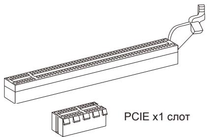
PCIEx16cnot
Cnot PCI (Peripheral Component Interconnect)
CnotPCI no3B0nraet yctaHObntb Kaptb LAN, SCSI, USB n dpyne donoONHteJbHbe Kaptb paacupeHHa, KOtOpbie COOTBeTCTByIOT cneunfkaun PCl.

32-bit PCI cnot
BhimhaHne
Ipeed yctaHOBKO uINu 3BneueHnem Kapr pacuHepnry ybeDntecb, yTo Ka6eNB nITAHNRA OTKNUOeyoT OJIeKTPnuECKo CETN. IpouHTte DOKyMeNTaCNo Ha KapTy paCUnPehnru IN BbINOHNTE HeoBXOIMbIe AnnpaTHbIe NIN npOrpAMhIE yCTaHOBKn Ira daHHo INaTBI, TAKNE KAK NepeMbUKN, nepeKluOaTeJIN NIN KOHfUrpaCIno BIOS.
MapuTn3aun 3anpocOB npepbHaHna PCI
IRQ - cokpaueHne ot interrupt request (line) - linna 3anpoca nppebvaHnna, annapaTHna JINHnno KOTOPoYcTPOJCTBA MOrTy NocBlaTaB CnHnA nppebBaHnMa MNKpOpoCeCCopy.
06bIyHoe NOdkJIIOUeHne PCI IRQ K KOHTaTAM IINHb PCI noka3aHO HIXKe:
| Приказ1 | Приказ2 | Приказ3 | Приказ4 | |
| PCI сnot1 | INT A# | INT B# | INT C# | INT D# |
| PCI сnot2 | INT B# | INT C# | INT D# | INT A# |
Hactpoika BIOS
B 3toi rnaBe npnboaTcO cHOBhIe CBeEHHa O pexmHe hactpoKn BIOS (BIOS SETUP), KOtOpbI n03BOJAE TcAHOBHT ONTMaJIbHyO KOHpIgpyaUHcCTeMbI. 3TO t peXIM MoKeT Notpe6oBaTcBcR B CneDyUOxClyuayx:
Bo Bpemr 3aarpy3kn cnCTeMbI NOBnreTc COo6uHHe o6 Oun6Ke c Tpe6obAHmE 3anyctntb BIOS SETUP.
B cnyuae Heo6xoJIMOCtI 3aMeHnTb 3aBOcKne HAcTpOKn Ha cObCTBeHHbIe.
BHTMAHNE
PCI Subsystem Settings
ACPI Settings
Integrated Peripherals
On-Chip VGA Devices
IIN DBaXdbI ueKNHnTe IeByIO KNOpKy MbIiN, YTo6bI Bb3BaTb NOMeHIO. DaIee MOxHO NCNoB3OBA Tb ynpabJrIoUne KnaBnUs Ipn BBoa npaMeTpOB IN nepemeueHnno NyHKtAm NoDMHeIO. YTo6bI BepHyTbcra B rIaNbHoe MeHIO, IpocTo haxMnte
Подробная справka
B pexime hactpoikn BIOS nmeetc B03MOXHOCTb nonyehnna npdo6ho ncpaBKn. Ee moxho BV3BaT bN 3IIO6O ro MeHIO npocTbIM HaxaTneM < F1> .B OKHe cnpaBKn 6ydt nepeuNCJIeHb BCE BO3MOXHbIE hactpoiKn B BVbpaHHOM nyHKTe MeHIO.Haxmnte < Esc> dIra BblKIIUoyehnOKHa cnpaBKn.
The Main Menu (Главhoe Meно)
Pn Bxode B pexkIM hactpoKBIOS Ha 3KpaHe oTo6paxaetcra TlaBHOe MeHIO. TnaBHOe MeHIO n03BOJare TBbpaT bCneDyUOJIe FyHKsN HactpoE.
Language
Пункт MeHIO, B KOTOPOM MOXHOи3MeHHTb TeKU7IЯ3bIK BIOS.
Green Power
IyHKMeHIO,BKOTOPOMMOXHOIMeHNbHaCTpOJKNpeJIMOB3HePrc6epeKeHnA.
Utilities
Пункт Meню, В КOTOPOM HaxoДЯТСЯ ПОЕЗHBIE nporpamMbI ДЯ abTomatUeCKORO 6OBHbENHRI BIOS IN co3dAnH 63Kana HDD.
Overclocking
Current CPU / DRAM Frequency
3TN nyHKtbl noka3bIbaIOT TekyuH yacToTy CPU u ckopocTb namrTu. TOnbKO dnyuTeHn.
CPU Base Frequency [10KHz]
3TOT nyHKT NO3BOJAEY cTaHOBnTB TaKTOBy YAcToTy Base clock CPU (B 10KHz). NImeHHe 3TORO napameTpA o6ecneuBaET BO3MOxHocTh pa3roHa CPU. BnMaHne, BO3MOxHocTh ycNeuHoro pa3roHa He rapaHTnpyETcR.
Adjust CPU Ratio
ÖTOT NyHK T KONTHPONINPYeT MHOKHTeB, PpeHa3NaueHHbI DnI ONpeDeJIENH BNYTpEHHe TAKTOB0 YACTOTbI PPOUCEccopa B COOTBETCTBn C BHeUHe N TakTOB0 YACTOT0I INI YACTOTOI CNCTEMHOI PNaTbI. OH DoCTyneH TOJbKO ToTda, KOrDa IPOUCEccOP NOIDepKINBaET 3Ty fYHKUIO.
Adjusted CPU Frequency
3TOT nyHKT noka3bIbaeTekuSyu qactoty CPU. TOnbKO dny tTeHnA.
Adjust CPU Ratio in OS
BknIOHTe 3OT nyHKT, OH nO3BOJAEr Bam n3MeHnTb yAcToTy CPU B OC cpeIcTBOM npInoKeHn r MSl.
Internal PLL Overvoltage
3TOT nyHKT nCOnb3yeTcI dIe pernJInpOBAHnHa npRjXeHn PLL.
EIST
TexHONorra Enhanced Intel SpeedStep no3B0JAEyCTaHOBnTB yPOBeHb npOn3BOUnteNbHocTNI MKNpOnpoueccopa. 3OT nYHKT NOBJIETcN oCNe yCTaHOBKn npOceccopa, KOTOpBNoDpeKnBaET TexHONOru SpeedStep.
DRAM Frequency
IyHKYnpaBneHnYacTOnAMn namrN.
Extreme Memory Profile(X.M.P)
3TOT nyHKT no3BOJAREB KIIIOUHTb/BykIIOUHTb Intel Extreme Memory Profile (XMP). 3a DOnONHnTeBJHO INΦOpaMauné ObaaauTeCb Ha oΦuHaJIbHbI Be6caIIT Intel.
Adjusted DRAM Frequency
3TOT nyHKT noka3bIaET TekyuTo yactOry DRAM.ToIbKO dIyTeHnA.
DRAM Timing Mode
OnpeJeT 6dyt IIN TaIMeHr DRAM KOHTpOInpoBaTcBdAHHbIMn 3SPD (Serial Presence Detect) EEPROM Ha moUyne DRAM. PIn BbIbope 3NaueHnra [Auto]TaIMnIR DRAM, BKJIouyA pyHKTB MeHIO, nepeuNCleHbIe HNKe, yCTaHaBnBAOTcBIBOS B COOTBeTcBmC daHHbIMn n3 SPD. YCTaHObKa 3NaueHnB [Link] nn [Unlink]P03BOJnEe BPuyHyIO peryNIPOBaTb TaIMnIR DRAM DOctTyHbIe B 3Tom MeHIO.
Advanced DRAM Configuration
Haxmnte
Command Rate2
3Ta NaCtpoKa KOHtpnIpyET DRAM command rate.
tCL
3TOT nyHKT KOHTpOJIpyET BPEM 3aIepKKn CAS, KOTOpoe onpeJeIeT nepIOd (B TaKtax reHepaTopa) Mekdy nolnyehnem naMaTbIO SDRAM KOMaHdbI UTeHnra NaHaJalom ee BbINOJIHeHnra.
tRCD
念 TOT nyHKT nCNoIb3yeTcra Iy cTaHOBK TaMmHROB tWCL (Write CAS Latency).
tCKE
TOT nyHKT nCnOJb3yETcI yCTaHOBKn taIMnHroB tCKE.
Advanced Channel 1/2 Timing Configuration
Haxmnte
- tRRDR/tRRDD/tWWDR/tWWDD/tRWRDD/tWRDRDD/tRWSR
3Tn NyKtbI NcNoJIb3yIOrTaI yCTaHOBKn TaIMMHROB nAmrTu KaHaNoB 1/2.
GT OverClocking
3TOT nyHKT NO3BONJET BKNIOHTb/ BBKNIIOHTb pa3rOH BnDEOkaPTbl.
GT Ratio
3Ta NaHCTpOJa KOnTHpONHyET OTHoUHeNte TaKToBOn YAcTOTbI BnDeOKeApTbI, YTObI OHa pa6Otae T Ba3hIx COyTeAHnX YAcTOT.
Spread Spectrum
Tak kak TakTOBbI rHeHApOp CnCTeMHOn pIaTbI NmNpyLbChbI, To erO paBOta BblBaet 3JIeKTPomarHHTbIe nomexi - EMI (Electromagnetic Interference).ФункцЯ Spread Spectrum chnkaet 3tN nomexi, reHepnpy crnaKeHHble nMnylcbI.
Bhuvahine
-
Ecnn y Bac Het npo6nem c nomexamn, octabte 3naeHne [Disabled] (3anpeueho) Дялушew CTaBnIbHOCTN n npOn3BOuNTenbHOCTN. Ondako, ecnn y Bac BO3HnKaOT 3NeKTPomarHHTbIe nomexn, Bbl6epnte Spread Spectrum Дя nx yMeHbSeHnry.
-Чем сожае 3начени Spread Spectrum, Tem Нже 6удет уровьп злесгомагншьixnomex,ностemaстанet монeeстаньhoи.Дя вьбopa рохюцero 3начени Spread Spectrum, CBepbtecs co 3начениMu npobhenзлесгомагншьixnomex,yctahOBNeHHbix 3akOHoDAteNBCTBOM. -
He 3a6ydbte 3anpeticnncb30bAHne yHKcnn Spread Spectrum, cnn Bbl «pa3roHaeTe» cnctemHyIO pNAty. 3To Heo6xOIMo, TAK Kac daxe He6onbwoi Dpe6e3r CnHaIOB TaKTOBO rEhepatopa MoKeT npNBecTI KOTka3y «pa3orHaHHoro» npouceccopa.
VDroop Control
3TOT nyHKT nCIOJIb3yETc dIa BB6opa peKIma VDroop control. - CPU Core Voltage/ CPU I/O Voltage/ DRAM Voltage/ GPU Voltage/ System Agent Voltage(SA)/ CPU PLL Voltage/ DDR_VREF_CA_A/ DDR_VREF_CA_B/ DDR_VREF_DA_A/ DDR_VREF_DA_B/ PCH 1.05
Tn npKtbI no3BOJIAOT perynnpoBaTB napjKeHne CPU, naMrtn, uYnceta. - Current CPU Core Voltage/ Current CPU I/O Voltage/ Current DRAM Voltage/ Current GPU Voltage
3Tn nykTBI noka3bIbaOT Tekyuee HappKeHne CPU Core/ CPU I/O/ DRAM/ GPU. TOnbKO dIyUTeHnIa.
Overclocking Profiles
HaxmTe
Overclocking Profile 1/2/3/4/5/6
Haxmnte
OC Retry Count
При HeудачHom pa3roHe, yctaHOBka 3TOrO nyHKTa B [1, 3] no3BOJЯгс CTeMe nonbIaTbc3 aRpy3nTbc3 1/3 pa3a c 3aDaHHo KOnФиrgupaUnei. EcIn 3arpy3nTbc3 He ydaJIaCTbcB Cte Tprn pa3a, CnCTeMa BOCCTaHOBHT NaCtpoJKN no yMOnUaHHIO.
CPU Specifications
Haxmte
CPU Technology Support
Haxmnte
MEMORY-Z
Haxmte
DIMM1~4 Memory SPD
HaxmTe
X.M.P Support Information
Haxmnte
CPU Features
Haxmnte
Hyper-threading
http://www.intel.com/technology/platform-technology/hyper-threading/
Active Processor Cores
TOT nyHKT no3B0JraET bIbpaTB KOJIuYeCTBO aKTHINbHx Jaep npoueccopa.
Limit CPUID Maximum
3TOT nyHKT npedHa3NaueH dIg ORpaHueHn DIIHHbI IeHTnФkaUHOHOrO HOMepa npoceccopa nepedaBaemoro B OepaONHHyCnCTeMy.
Execute Disable Bit
IcnoIb3OBAHnE TexHONOrn Execute Disable Bit Intel no3BOnrTe n36eRaTb yraBIMocTeBbl3bBAembIX BpeHOChbIMn nporpaMMAMn EKcnIpyuOUMM OoN6Kn Tnna "buffer overflow", ecn 3Ta texHONOrn NOdepxJNaBaETcNOpeaONHO cnCTEmo. Oha No3BOnrTe npouecCPy pa3deJeTb 30hB b pAmrN B COOTBeTcBmC TeM, xpaHITcJn B pAmrN IcNoJIHeMbY kOd nIn Het. KOrDa BpeHOCha nporpAMMa nonbTaetcBCTaBnTB kOd B 6yDcp, npouecCP 3anPepNT uCNoJIHeHne KOD, YTO OCTaHOBnT paCnpocTpAnHeHne BpeHOCHOINpOprpMMbl.
Intel Virtualization Tech
3TOT nyHKT NcNOJb3yeTc DnIe BkNIOUeHn/BykNIOUeHn TExHONOrn Intel Virtualization. 3a DonoHnTeBHOH INHOpMaunE cmOtpnte oΦΦnuaNbHb Be6caNT Intel.
Intel VT-D Tech
3TOT nyHKT nCNOJb3yETc DnI BKJIIOUeHnB/ByIKNIOUeHn TExHOJorIN Intel VT-D. 3a donONHtJIbHOn INΦOpMauné CMOpTne OΦΦuNaJIbHbI Be6caIT Intel.
Power Technology
念 TOT nyHKT no3B0JAEr BbIpaTaB peKIM texHONorIN Intel Dynamic Power.
C1E Support
BkIouHte 3OT nyHKT dIa CHNKeHn 3HeprOnoTpe6JeHnCy, KOrda OH hepap60taet. He Bce npocecoppb noDdepxmbaot Enhanced Halt state (C1E).
OverSpeed Protection
Функця Overspeed Protection oTo6paxaet noTOK BbIuNcIeHn CPU n er0 3hepronoTpe6IeHne. Ecnn OHO npEBicNT onpeJeHHybl ypoBeHb, To npouceccop
abTomatueckn noHn3NT TaKToBvO uactOty. Ecnn Bbl co6npaTecb pa3roHrTB CPU, To yctahOBITE 3TOT npaMeTp B [Disabled].
Intel C-State
C-state - 3TO texHONORn ynpaBneHn nITaHnEM, npK TINBaUN KOTOpO 3NaHTeJbHO naJaET 3HePRO nOTpe6bHeHne npoCeCCopa B cPraUeM pexnme. 3TOT nyHKT DocTyneH ToJIbKO npn IcNoIb3ObaHnn CPU c noDdepKkoTexHONORn Cstate.
Package C-State limit
3TOT nyHKT no3BOJRAET Bb6paTb C-state limit.
> Long duration power limit(W)
3TOT nyHKT no3B0JraTe peryIINPOBaT bIMNT MoUHOCTN TDP B TeueHn npoDOLKInTeJbHoro BpeMeHn.
Long duration maintained(ms)
3TOT nyHKT n03BOJnEYcTaHOBnTB BpempaOToBb NpeperpyKeHHOM pexKIme.
> Short duration power limit(W)
3TOT nyHKT no3BOJRAET peryIINPOBaTb JIMNT MOUHCTN TDP B TeueHN KOPOTKORO npomexyTKa BpeMeHN.
Primary plane turbo power limit(W)
3TOT nyHKT no3BONJET peryIINPOBaTb JIMNT MOUHOCn TDP nIe npBnuHoro/ BTOpHoro plane turbo.
CBeHeHnO npOrpaMMHom oecneueHn
YctahOBtte B npBOD nck Driver/Utility (DpaBepb y tntbl) n3 kOMnKeTa nocTakn CNTeMHo nIaTb. ABToMaTuYeCKn 3anycTnTCra NcHCTaJIaIyra. HaxMITE Ha ha3BaHne dpaiBepa/ ytnlntbl n cndyTe nHcTpkyqumHa 3kpaHe nla3abepseHn HnCTaJIaIyau. Dnck Driver/Utility codepKHT:
- Driver menu (MeHIO npaiBepOB): IpeIcTabIeT nepeueHbIOCTyINbIX dpaiBepOB. YctahOBiTe DpaBepbl dny noKJIoueHn Heo6xOIMbIX yCTPOIcTB.
- Utility menu (Meho ytni): P03BONaT yctahOBnTB doCTynHbIe ytniNbI.
Service base menu (MeHIO cepBnCHoI 6a3bI):P03BOJAEr T coeINHTb OΦnuaJIbHbI Bé6caI r MSI. - Product info menu (Мени难得): Покаastics Novelny История о поodyк tax MSI.
- Security menu (MeHIO 6e3onacHOCTN): PpeIcTabIeT noJIe3HbIe aHTINBUPyCHbIe npOrpaMMbl.
BhIMaHHe
Ioxayncta, noceTne Be6caT MSI nna nonyuhenra cambIX HObIX dpaiBepOB IN BIOS, KOtOpBie no3BOJAT yNyUHTb npOn3BOJNTeHbOCTb CnCTeMbI.