
DoorPhone AP2 - Smart Home Evolveo - Free user manual and instructions
Find the device manual for free DoorPhone AP2 Evolveo in PDF.


| Product Type | Smart Door Phone |
| Model | DoorPhone AP2 |
| Dimensions (approx.) | 150 x 70 x 30 mm |
| Weight (approx.) | 200 g |
| Power Supply | PoE (IEEE 802.3af) or DC 12V |
| Connectivity | Wi-Fi 802.11 b/g/n, Ethernet |
| Video Resolution | 720p HD |
| Field of View | 120° horizontal |
| Night Vision | Yes, IR LEDs up to 5 m |
| Audio | Two-way audio with noise cancellation |
| Motion Detection | Yes, adjustable sensitivity |
| Remote Unlock | Via mobile app |
| Mobile App | Evolveo Smart Home (iOS/Android) |
| Weather Resistance | IP54 |
| Operating Temperature | -10°C to 50°C |
| Memory Card Support | MicroSD up to 64 GB (optional) |
| Maintenance | Clean with a soft, damp cloth; avoid solvents |
| Safety | Low voltage, CE certified |
| Warranty | 2 years |
Frequently Asked Questions - DoorPhone AP2 Evolveo
User questions about DoorPhone AP2 Evolveo
0 question about this device. Answer the ones you know or ask your own.
Ask a new question about this device
Download the instructions for your Smart Home in PDF format for free! Find your manual DoorPhone AP2 - Evolveo and take your electronic device back in hand. On this page are published all the documents necessary for the use of your device. DoorPhone AP2 by Evolveo.
USER MANUAL DoorPhone AP2 Evolveo

Obsah / Content / Tartalom / Cuprins
Česky 4
Slovensky 40
English....76
Magyar....112
Română 149
CZ
SK
EN
HU
RO
Obsah
- FUNKCE A MOŽNOSTI SYSTÉMU 4
- BALENÍ......4
- TECHNICKÉ SPECIFIKACE 4
- INFORMACE O PRODUKTU EVOLVEO DOORPHONE AP1 ...... 6
- INFORMACE O PRODUKTU EVOLVEO DOORPHONE AP10 8
- SCHÉMA STANDARDNÍ SADY AP1 / AP10 10
- INFORMACE O PRODUKTU EVOLVEO DOORPHONE AP2 / AP20...... 12
- INFORMACE O PRODUKTU 13
- SCHÉMA PŘIPOJENÍ 2 MONITORŮ – FUNKCE INTERKOMU.... 13
- SCHÉMA PŘIPOJENÍ VÍCE MONITORŮ- FUNKCE INTERKOMU ...... 14
- ČTEČKA RFID KARET – NASTAVENÍ AP2/AP10/AP20 14
- OVLÁDÁNÍ MONITORU 19
- ROZHRANÍ VIDEOTELEFONU 20
- INTERKOM A NASTAVENÍ TLAČÍTEK ZVONKU PRO AP2 A AP20 ...... 20
- NASTAVENÍ....24
- OSTATNÍ NASTAVENÍ - VLASTNÍ TAPETA A VYZVÁNĚNÍ...... 27
- KROKY OVLÁDÁNÍ VIDEOTELEFONU A INTERKOMU V APLIKACI 28
- PŘIDÁNÍ A PŘIPOJENÍ APLIKACE Smart Life 29
- SDÍLENÍ S OSTANÍMI UŽIVATELI 30
- MONTÁŽ MONITORU A VENKOVNÍCH JEDNOTEK 31
- ÚDRŽBA ZAŘÍZENÍ 33
- BEZPEČNOSTNÍ UPOZORNĚNÍ...... 33
- UPOZORNĚNÍ A ŘEŠENÍ NEJČASTĚJŠÍCH PROBLÉMŮ...... 33
1. FUNKCE A MOŽNOSTI SYSTÉMU
Venkovní jednotka
Pohled zezadu AP10
- V+ 2. NC 3. NO 4. COM 5. GND


19. SDÍLENÍ S OSTANÍMI UŽIVATELI
Krok 4: Zvolte Tuya App Account

PŘIPEVNĚNÍ VENKOVNÍ JEDNOTKY AP2/AP20
PŘIPEVNĚNÍ VENKOVNÍ JEDNOTKY AP10
21. ÚDRŽBA ZAŘÍZENÍ
Copyright © Abacus Electric, s.r.o.
www.evolveo.com

CN11: Pripojenie k napájaniu DC 18 V.
Vonkajšia jednotka
8. INFORMÁCIE O PRODUKTE
▶ ID stanice (SW4 Dip setting).
| PREPÍNAČ DIP | ID stanice ourdoor | PREPÍNAČ DIP | ID stanice ourdoor | ||
 | 1 |  | 5 | ||
 | 2 |  | 6 | ||
 | 3 |  | 7 | ||
 | 4 | ||||
9. SCHÉMA ZAPOJENIA 2 MONITOROV - FUNKCIA INTERKOMU
Doma - Po stlačení vonkajšieho tlačidla monitor zvoní 30 sekúnd a potom odošle upozornenie.

Zadanie hesla WIFI
Iné > Jazyk

Angličtina, Čeština, Slovenština, mad'arčina, rumunčina, nemčina, Taliansky
Iné > Systém
16. ĎALŠIE NASTAVENIA - VLASTNÉ TAPETY A ZVONENIA
Krok 6: Úspešne pridané a kliknite na tlačidlo "Hotovo"

19. ZDIEŁANIE S OSTATNÝMI POUŽÍVATEL'MI
Krok 4: Zvolte Tuya App Account

Pripevnenie monitora k držiaku:
MONTÁŽ VONKAJŠEJ JEDNOTKY AP2/AP20
PRIPEVNENIE VONKAJŠEJ JEDNOTKY AP10
Copyright © Abacus Electric, s.r.o.
www.evolveo.com
1. SYSTEM FEATURES AND OPTIONS
- Owner's communication with visitors.
- Increased house security.
• Electric door lock control. - Visual inspection of the visitor before entering the house.
- Infrared illumination of the area in front of the camera ensures a clear image even at 0 Lux illumination.
- 7" TFT LCD display or 10.1" TFT LCD display.
• Intercom communication between monitors.
• A choice of ringtones. - Possibility of hanging the videophone on the wall.
2. PACKAGING
After opening the box, it is recommended to check the contents according to the following list:
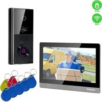
• Monitor (For AP2 and AP20, 2 monitors are included.)
- Mounting frame for monitor.
- Fixing screws.
- Door camera unit.
- Mounting frame for surface mounting of the camera unit + gasket.
• Power supply (2 power supplies are included for AP2).
- Cables fitted with connectors for interconnection.
- Lever clamps for easy cable connection.
3. TECHNICAL SPECIFICATIONS
Indoor unit 7
- 7" LCD monitor with touch screen
● Power adapter: Input: AC 100-240V Output: DC 18V 1000mA - Standby power consumption 1.5W and working mode 10W
- Connection: 2 PIN
● Monitoring time: 30 seconds - Operating temperature: -20°C - +60°C
- Dimensions (HxWxD): 160 x 240 x 28mm
Outdoor unit
- Single button door station - brushed aluminium
● Professional CCD camera with IR illumination -
Standby/operating mode 1W
● Night light: 7m - IR LED 850nm -
Operating temperature -20°C - +60°C
- Mounting height: 145 – 160cm
- Dimensions (HxWxD): 165 x 95 x 45mm

Indoor 7" Wifi monitor
| 1) System: Linux2) Connection method: 2 wires without polarity, diameter max. 0,75 mm23) Functions: Video communication, monitor, unlocking4) Resolution: 1024*6005) Method of communication: Two-way voice | 6) Call time: 60 seconds7) Power input: 10W; standby: 1,5W8) memory/video card, WiFi9) Working voltage: DC 18-24V10) Working temperature: -10°C - +60°C11) Maximum capacity: 128GB |

Indoor 10" Wifi monitor
| 1) System: Linux2) Connection method: 2 wires without polarity, diameter max. 0,75 mm23) Functions: Video communication, monitor, unlocking4) Resolution: 1280*8005) Method of communication: Two-way voice | 6) Call time: 60 seconds7) Power input: 10W; standby: 1,5W8) memory/video card, WiFi9) Working voltage: DC 18-24V10) Working temperature: -10°C - +60°C11) Maximum capacity: 128GB |


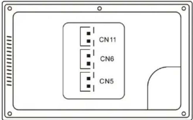
CN11: Connection to DC 18V power supply.
CN6: Connection to outdoor unit
CN5: Connect to another internal monitor.
4. PRODUCT INFORMATION EVOLVEO DOORPHONE AP1

Outdoor unit
- Outdoor / Door Station
- Resolution: 2MPx 1080P
- Video streaming: H.264
- Communication: Two wires without polarity
- Function: video and audio transmission
- Call time: 60 seconds
- Waterproof: IP65 when properly installed with sealing
- Night vision: yes
- Standby: 1W
- Work performance: 2W
- Tension: DC 18-24V
- Operating temperature: -10°C +60°C
- Locks: 2x relays
- Dimensions (HxWxD): 165 x 95 x 45mm
- Relé max 1A/24V

Front view
jumper 2: deployed, disconnection as CN3 without power output.
jumper 1: disconnection as CN3 for connection of electronic lock.
jumper 3: for door station ID, deployed as id 1, disconnected as 2.
CN1: for the lock opening button CN3.
CN2: for the lock opening button CN4.
CN3: To lock 1 (the door station can offer power to the electronic lock, the magnetic lock must be connected to an external power source).
CN4: To lock 2 (lock must be connected to external power supply, NO and COM connected to magnetic lock, NC and COM connected to electronic lock).
CN5: Indoor Monitor
- PRODUCT INFORMATION EVOLVEO DOORPHONE AP10
| 133mm |  | 31. IC: 3918V33032. Dimensions: 133 x 63 x 37mm33. Resolution: 2MP 1080P34. Video stream: H.26435. Communication: two-way36. Function: calling and communication37. Call time: 60 seconds38. Waterproof: IP65 when properly installed with sealing39. Night vision: yes40. Standby mode: 1W41. Work performance: 2W42. Tension: 18-24V43. Operating temperature: -10 - +60 °C44. Connection: 2 wires without polarity45. Locks: support connection of 2 locks, provides power supply for lock 0.5A/12VDC. |
| Outdoor unit | ||
 | 13. Microphone14. Illuminator for night mode15. Full HD camera16. RFID reader17. Button on the doorbell18. Speaker |
Wiring

Rear view AP10
- V+
- NC
- NO 4. COM
- GND
A: Output button for Lock 1
B: Output button for Lock 2
SW1: To set the door ID
SW3: Mounted Jumper = Power supply of the NO terminal on the CN connector is on, electronic lock 0.5A/12VDC can be connected
CN1: To the castle 1
CN2: To the castle 2
CN3: For button controlling locks CN1 and CN2
CN5: Indoor Monitor
K1: Setting button
![graph LR A["①"] --> B["jumper2"] B --> C["②"] C --> D["NO COM NC GND"] D --> E["③"] E --> F["NO COM NC"] F --> G["④"] G --> H["AC"] style A fill:#f9f,stroke:#333 style B fill:#ccf,stroke:#333 style C fill:#cfc,stroke:#333 style D fill:#ffc,stroke:#333 style E fill:#fcc,stroke:#333 style F fill:#cff,…](/content/2026/06/1382340/images/682534678b7f651ac171565f30c218bff53fe1c51c709701e7ffe10c06c10869.jpg)
Detailed connection With the lock diagram
1) Jumper 2 deployed
2) Electric lock
3) Power supply
4) Magnetic lock
6. DIAGRAM OF STANDARD SET AP1 / AP10
(1 outdoor station for 1 indoor monitor)
![graph TD A["Monitor"] -->|2C| B["Switch"] B --> C["AC"] C --> D["①"] D --> E["AC"] E --> F["③"] F --> G["④"] G --> H["+"] H --> I["AC"] I --> J["③"] J --> K["NC"] K --> L["COM"] L --> M["②"]](/content/2026/06/1382340/images/3108c89d45e5dddd26cccdd77fce8e00f6185ee68ddb29117203a5d833cb61bf.jpg)
1) Power adapter
2) Outdoor stations
3) Power supply
4) Magnetic lock
Detailed connection diagram AP1
![graph TD A["AC"] --> B["①"] B --> C["CN11"] B --> D["CN6"] B --> E["CN5"] C --> F["jumper1"] D --> G["jumper2"] E --> H["jumper3"] F --> I["⑥"] G --> J["④"] H --> K["⑦"] L["③"] --> M["2C"] M --> N["⑦"]](/content/2026/06/1382340/images/072aadef909c9a8e4f37a97e84f47c3307dee368c0c87d2c5532cd4ef1a1c405.jpg)
1) Input/adapter
2) Internal monitor connectors
3) Internal monitor
4) Detail of the connection of the two wires
5) 2 wires
6) Outdoor station connectors
7) Outdoor unit
Detailed connection diagram AP10
![graph TD A["Monitor"] --> B["adapter"] B --> C["CN11"] B --> D["CN6"] B --> E["CN5"] F["Outdoor"] --> G["cn3 for exit switch"] G --> H["SW2 SW3 SW1 CN5"] G --> I["CN1 for lock 2"] I --> J["K1"] J --> K["magnetic lock"] K --> L["power supply"] L --> M["AC"] M --> N["output"] O["2C"] --> P["electronic…](/content/2026/06/1382340/images/9858d9bd32b57bd57bc0053b5d8d93173677cb3521ce1269333c626f4ed15672.jpg)
Remark: 18V1A adapter as power supply:
- Diameter 0,2 mm 2 conductors - cable length max 40 meters.
- Diameter 0,5 mm 2 conductors - cable length max 80 meters.
- Diameter 0,75 mm 2 conductors - cable length max 100 meters.
7. PRODUCT INFORMATION EVOLVEO DOORPHONE AP2 / AP20

Front view
Outdoor unit connectors
1. NO 2. COM 3. NC 4. GND
CN3: To lock 1 (the door station can power the electronic lock, the magnetic lock must be connected to an external power supply).
CN4: To lock 2 (the lock must be connected to an external power source, NO and COM are connected to the magnetic lock, NC and COM to the electronic lock).
CN5: Connecting to an internal monitor.
CN1: Lock control button 1 (CN3). The button directly controls the lock without an app or internal unit - any button can be used.
CN2: Lock control button 2 (CN4) This button directly controls the lock without an application or internal unit - any button can be used.
SW1: disconnection as CN3 for connection of electronic lock.
SW2: connect as CN3 power output, disconnect as CN3 without power output.
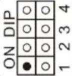
SW4: Station ID - only ID1 and ID2 can be set for this type according to the table below.
K1: RFID card learning button.
8. PRODUCT INFORMATION
▶ Station ID (SW4 Dip setting).
| DIP SWITCH | Station ID ourdoor | DIP SWITCH | Station ID ourdoor | ||
| 1 | | 5 | ||
| 2 | | 6 | ||
| 3 | | 7 | ||
| 4 | ||||
9. CONNECTION DIAGRAM OF 2 MONITORS - INTERCOM FUNCTION
(1 outdoor station for max. 2 indoor monitors)
![graph TD A["Computer"] -->|CN6| B["Switch"] B -->|2C| C["Server"] C -->|CN5| D["Switch"] D -->|CN11| E["AC"] E -->|CN11| F["Computer"] G["Computer"] -->|CN6| H["Switch"] H -->|CN6| I["Switch"] style A fill:#f9f,stroke:#333 style G fill:#f9f,stroke:#333 style C fill:#ccf,stroke:#333 style H fill:#ccf…](/content/2026/06/1382340/images/1bbbc31e29347f1d236337a540afdff8e3614500173be3eca520f10ee5010e30.jpg)
1) Power adapter
2) Outdoor stations
Remark: 18V1A adapter as central power supply:
- Diameter 0,2 mm 2 wires, max length 20 meters.
- Diameter 0,5 mm 2 wires, max length 50 m.
- Diameter 0.75 mm 2 wires, max length 100 metres
10. MULTI-MONITOR CONNECTION SCHEME - INTERCOM FUNCTION
(2 outdoor stations for max. 4 indoor monitors)
![graph TD A["Device ①"] -->|CN11 AC| B["Device ②"] B -->|CN5 2C| C["Device ②"] B -->|CN6 2C| D["Device ②"] E["Device ③"] -->|CN5 2C| F["Device ③"] E -->|CN6 2C| G["Device ③"]](/content/2026/06/1382340/images/bf05e2e89a6e154a791e16e40fd580d32cb4ab3775240fa63fff9964e2492fca.jpg)
1) power supply
2) outdoor stations
3) outdoor stations
Remark: 18V1A adapter as central power supply:
- Diameter 0,2 mm 2 wires, max length 20 meters.
- Diameter 0,5 mm 2 wires, max length 50 m.
- Diameter 0,75 mm 2 wires, max length 100 meters.
11. RFID CARD READER - AP2/AP10/AP20 SETTINGS

This device is used to control access using RFID cards. The user can use two relays to control the opening of gates, doors or doors. The RFID system allows easy and secure access for authorised persons.
The device allows you to add and remove RFID cards using an IR remote control or administrator cards. The cards are color-coded and preset from the factory:
Yellow card: Administrator card for adding user cards (factory default).
Red card: Administrator card for deleting user cards (factory default).
Blue cards: User cards for regular access.
(The cards are described in the original pack.)
The device supports two zones for RFID card learning:
Zone 1 (Relay 1): Up to 500 contactless cards.
Zone 2 (Relay 2): Up to 100 contactless cards.
1. Enter setup mode
Place the IR remote control close to the door station reader.
Press on the rotary pushbutton: *#1234# (default password is 1234).
This enters setup mode.
2. Manage cards using the remote control
A) Setting up cards in zone 1
Adding cards:
In setup mode, press button 1 on the remote control. There is a long "biii..." tone.
Add new user cards (blue) one by one. Each successful addition is confirmed by a short "bi" tone.
If a "bibi" tone is heard, the card has already been added.
When finished, press ** to exit.
Removing the cards:
In setup mode, press button 2 on the remote control.
Add the user cards you want to delete one by one.
When finished, press ** to exit.
B) Setting up cards in zone 2
Adding cards:
In setup mode, press button 7 on the remote control. There is a long "biii..." tone.
Attach new user cards (blue). Each successful addition is confirmed by a short "bi" tone.
When finished, press ** to exit.
Removing the cards:
In setup mode, press button 2 on the remote control.
Attach the user cards you want to delete.
When finished, press ** to exit.
3. Setting up administrator cards
A) Adding an admin card for zone 1
In setup mode, press 00 on the rotary pushbutton.
Attach the yellow card as an admin card for zone 1 (factory default).
Press ** to exit.
B) Adding an admin card for zone 2
In setup mode, press 33 on the remote control.
Attach the yellow card as an admin card for zone 2 (factory default).
Press ** to exit.
C) Setting up a tab for deleting user tabs
In setup mode, press 66 on the rotary pushbutton.
Attach the red card as an admin delete card (factory default).
Press ** to exit.
4. Manage cards using admin cards
A) Adding user cards using the admin card (yellow card)
Attach the admin card (yellow).
Within 5 seconds, add the new user cards (blue) you want to add.
When finished, reattach the admin card (yellow) to exit.
B) Deleting user cards using the admin card (red card)
Attach the admin delete card (red).
Within 5 seconds, add the user cards (blue) you want to delete.
When finished, reattach the admin delete card (red) to exit.
5. Delete all cards
In setup mode, press 99 on the rotary pushbutton.
After 5 seconds, a long "biii..." tone is heard, indicating that all cards have been successfully cleared.
6. To change the default password for setup mode
In setup mode, press 8 on the rotary pushbutton.
Enter a new 4-digit password.
Press # to confirm.
Enter the same new password again for authentication.
Press # to confirm.
Press ** to exit.
7. Using the K1 button
A) Restore the factory default password
Disconnect the device from the power supply.
Press and hold the K1 button on the back of the door station.
Connect the power supply, still holding the K1 button.
When the "bi..." tone sounds, release the K1 button.
The password has been reset to the default 1234.
B) Setting up admin cards using K1
In setup mode:
Press the K1 button once and insert the yellow card as the admin card for zone 1 (factory default).
Press K1 a second time and insert the yellow card as the admin card for zone 2 (factory default).
Press K1 for the third time and insert the red card as an administrator card for erasing (factory default).
Press K1 a fourth time to exit.
Notes
Sound signaling:
A short "bi" tone confirms successful action.
A double "bibi" tone means that the card has already been used or the action could not be performed.
Security:
Keep the administrator cards (yellow and red) in a safe place to prevent unauthorized management of the device.
Remote control:
Make sure that the controller is close enough to the reader during setup.
Setup mode:
If no action is taken within 60 seconds, the device will automatically exit setup mode.
- MONITOR CONTROL
13. VIDEOPHONE INTERFACE

1) Selected door stations
2) Monitor and call time countdown
3) System time
4) SD memory card status
5) Termination/return
6) Unlocking the door 2
7) Unlocking the door 1
8) Reply
9) Record
10) Images
11) Setting the ringer volume
14. INTERCOM AND DOORBELL BUTTON SETTINGS FOR AP2 AND AP20
These devices are equipped with an outdoor unit with two buttons that allow each button to ring a different monitor when pressed. Each button on the outdoor unit is assigned to a specific monitor using the device ID setting. The intercom function allows communication between monitors that have the same room ID (Room ID - only one door station button is used).
1. Assigning Bell Buttons for individual monitors
What it's for:
The Room ID determines which monitor will respond to a specific button press on the outdoor unit.
Allows each monitor to receive calls only from the assigned button.
How to set it up:
Press the Settings button to open the menu on the monitor.
Select Set ID.
Enter the password 1234 and confirm.
Set the desired Room ID:
0001 for top button (button 1)
0002 for bottom button (button 2)
Confirm the settings by pressing the back button.
Practical applications:
Example: If you want the monitor to ring when you press the bottom button (button 2) on the outdoor unit, set room ID 0002 on the monitor to 2.
This setup is ideal for two-family homes or apartments with two separate units, where each unit has its own monitor.

Enter the number of the new room (0001-9999).
Enter the default password 1234 and enter the system.
2. Intercom function
What it's for:
Allows internal communication between monitors within the same home or office.
Useful for calling the family together for dinner, asking for help or communicating quickly without having to go to another room.
How to use it:
Make sure the monitors have the same room ID set.
On the monitor, press the Intercom button marked with the handset icon.
Select the monitor you want to contact (if available).
Wait for the other monitor to answer the call.
Practical applications:
Communication between floors: You can easily communicate between the ground floor and the first floor.
The children's call: Call the kids that it's dinner time without going to their room.
WARNING: In an installation with more than one monitor, it is necessary to set a different device ID for each monitor, this is the address of the monitor on the network, if multiple monitors have the same device ID you will see the message "Device ID repeat!"

![graph TD A["23:24<br>2022-06-13 Monday"] --> B["Intercom"] B --> C["1 ID3"] B --> D["2 ID4"] B --> E["3 ID3"] B --> F["4 ID3"]](/content/2026/06/1382340/images/57c461ee5c7093535cd3e831080e2b065561189b29c1b9da6dc3253a5e06d23a.jpg)
The image and video can be enlarged.
4. MONITOR MODES
Modes (At home, Away from home, Do not disturb)

At home - When the outdoor button is pressed, the monitor rings for 30 seconds and then sends an alert.
Outside Home - When the outside button is pressed, a voice outside will say "Leave message" - leave a message.
Do not disturb - For when you don't want to be disturbed. When the outside button is pressed, no chimes sound, instead the display shows a visual alert for 30 seconds, followed by an alert being sent."
15. SETTINGS
Selecting the ⚙️ icon will open a menu with the following items
Set Ringer, Set Room ID, Time Setting, Screen Saver, Other

Ringtone settings

- Challenge: There are six preset ringtones or you can insert your own ringtones. On the SD card create a folder "ring", The names of the individual files must be 1,2,3.mp3.
(e.g: 1.mp3)
Files must be mp3 files. Maximum size 1MB. A maximum of 100 custom tones can be inserted.
- Ringing time: 10, 20, 30, 50, 60 seconds.
- Doorbell: Outdoor station volume 0-100%.
- Challenge: Indoor station sound volume 0-100%.
Time settings

- Time and date settings (when connected to the internet, the system automatically updates the local time).
Screensaver

Other

Other > Wifi

Other > Language

Other > System

System information: software version, SD card status and device ID can be displayed
Other > Forming

You can format the memory card and restore the factory settings of the internal monitor.
Other > Security password

The security password is for the service, users do not have to work with it.
Default password 1234.
Other / Find an outdoor unit

Press the door station call button for more than 5 seconds to pair with the monitor. After successful pairing, the Exit button is displayed
16. OTHER SETTINGS - CUSTOM WALLPAPER AND RINGTONES
- Record: Select the recording method: Photo, Video, or Off - depending on the setting, the image is recorded when the door station button is pressed.
- Motion detection: Turns on motion detection in front of the camera, valid only for the door unit set as number 1.
- Update: Used for service purposes, it is necessary to have a file with the latest FW version
- Wallpaper settings: You can insert your own file and use it as a wallpaper on your monitor. Create a folder called "picture" on the SD card and insert the 1024*600 resolution .jpg files into it. Each image must be named 1.jpg, 2.jpg, 3.jpg, etc. Size max 1 MB. A maximum of 100 files can be uploaded.
-
Custom ringtones: you can insert your own ringtones. On the SD card create a folder "ring", The names of the individual files must be 1,2,3.mp3.
(e.g: 1.mp3) Maximum size 1MB. A maximum of 100 custom tones can be inserted. -
STEPS TO CONTROL THE VIDEOPHONE AND INTERCOM IN THE APP

Step 3: Press the door to unlock lock 1 or lock 2

18. ADDING AND CONNECTING A SMART LIFE APP
Setting up the Smart Life mobile phone app. Make sure the mobile phone is close to the monitor and the 2.4GHz WIFI router.

Step 1: Connect the mobile phone to the same WIFI with the WIFI monitor. And download the SmartLife or Tuya app in GooglePlay or the Appstore on iOS.
Step 2: click on the "SmartLife" app to add

Step 3: Search and pairing

Step 4: A device is found on the WIFI network - click the "add" button

Step 5: Adding

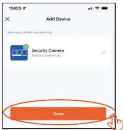
Step 6: Successfully added and click "Done"

Step 7: Setting the device name when you click on the "pencil"
19. SHARING WITH OTHER USERS
New users must register a new account.
Step 1: Click on the "Me" tab and then "Manage"

Step 2: Choose your household

Step 3: Add members
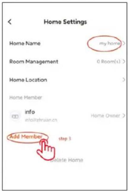
Step 4: Choose Tuya App Account

Step 5: Enter the user's name, and enter the account number, phone number or email of the next user below.

Step 6: New user added

20. INSTALLATION OF MONITOR AND OUTDOOR UNITS
The package also includes a set of screws and dowels for fixing. Use the fixing frames as a template to mark the holes to be drilled.
For mounting the indoor monitor, the KU 68 wiring box can be used, which has a distance of screw holes identical to the metal monitor bracket.
Outdoor unit AP1 - also allows mounting directly on the wiring box KU 68.
Warning: When installing outdoor units, always use the supplied rubber gaskets as shown in the following illustrations. Always secure outdoor units with screws. The package includes a Torx screwdriver for easy fixing.

Attaching the monitor to the bracket:
Carefully slide the monitor onto the tabs shown and push downwards.
ATTACHING THE OUTDOOR UNIT AP1
Follow the picture below. After sliding the outdoor unit into the frame, secure from the bottom with the screw provided. Always use the supplied gaskets for installation.

AP2/AP20 OUTDOOR UNIT MOUNTING
Follow the picture below. After sliding the outdoor unit into the frame, secure from the bottom with the screw provided. Always use the supplied gaskets for installation.

ATTACHING THE OUTDOOR UNIT AP10
Follow the picture below. After sliding the outdoor unit into the frame, secure from the bottom with the screw provided. Always use the supplied gaskets for installation.

21. EQUIPMENT MAINTENANCE
The monitor is low maintenance. It is recommended to wipe it with a damp cloth approximately once a month, depending on the degree of soiling.
WARNING ! - The device must be disconnected from the mains adapter before cleaning.
22. SAFETY NOTICE
- Do not place the videophone near TV receivers or in an environment with high temperature or humidity.
- Do not disassemble the monitor or door station.
- When direct sunlight hits the door station lens, the image on the video monitor may become unreadable.
- Do not expose the device to vibrations and drops.
23. ALERTS AND SOLUTIONS TO COMMON PROBLEMS
To ensure safe and proper operation of the equipment, please observe the following instructions:
Electrical safety:
Always disconnect the power supply before installing or servicing the equipment to prevent electric shock.
Use only power adapters with the appropriate output voltage and current as specified by the manufacturer (e.g. 18 V output voltage).
Location of the door station:
Install at a height of 150-170cm from the floor
Avoid direct sunlight or strong strong lighting directed directly at the lens.
Protection from the weather:
If the door station is exposed to harsh conditions, consider installing a canopy or protective cover. The monitor is not weatherproof and can only be installed indoors. Prevent moisture from entering the equipment to avoid damaging the electronics.
Maintenance:
Regularly clean the device with a soft cloth without using aggressive chemicals.
Do not use sharp or metal objects that could damage the surface or components of the device.
Safety in use:
Do not tamper with the equipment.
Keep passwords and admin cards in a safe place to prevent unauthorised use of the device. Train household members in the safe use of the device and warn them of the risks of opening the door to strangers.
Monitor unresponsive / black screen
Cause: The monitor is not properly powered or the adapter is defective.
Solution: Make sure the monitor is properly connected to the power adapter.
Use a multimeter to measure whether the correct voltage is present at the output of the adapter (usually 18 V, according to the device specification).
If you do not measure any voltage at the output of the adapter:
Check that the power socket is live.
If the socket is functional and the adapter does not work, the adapter is probably defective.
Replace the adapter with a new one with the appropriate output voltage and current according to the device specifications.
Device does not have clear picture/sound, does not ring
Cause: Possible wire breakage or incorrect parameter settings.
Solution: Take off the monitor and indoor unit and connect them directly with a short cable to avoid breaking any wires in the house. Check the picture and sound settings (brightness, contrast, color, volume). Make sure the cables are not damaged and are properly connected.
The lens is dewing
Cause: Condensation due to the temperature difference between the wall and the door station.
Solution: Dry the outdoor unit thoroughly.
Provide better insulation between the outdoor unit and the wall to reduce the temperature difference.
Consider using sealing or insulating materials suitable for outdoor use.
Spontaneous ringing
Cause: Moisture entering the camera causes the contacts to short out.
Solution: Disassemble the outdoor unit and dry it thoroughly.
Check the supplied seals and make sure the surface under the station is level to prevent water from entering the door station. In the event of fluid ingress into the outdoor station, poor installation is always to blame, and this defect is not covered by the warranty.
Whistling (feedback)
Cause: Reflection of sound from the speaker back to the microphone.
Solution: Lower the speaker volume on the monitor and door station.
Make sure the monitor and door station are not placed too close together.
Check that the microphone or speaker is not damaged or dirty.
It doesn't open the lock
Cause: Insufficient voltage or interrupted wiring to the lock.
Solution: Check the integrity of the wiring to the lock. Use a multimeter to measure the voltage at the lock terminals (the lock usually requires 12 V).
If the voltage is lower than required:
Use wires with a larger cross section to reduce resistance and voltage drop. Make sure that the lock's power supply provides sufficient current.
Sudden drop in microphone sensitivity
Cause: Contaminated microphone hole.
Solution: Clean the microphone hole with a soft, blunt object (e.g. a toothpick or cotton bud). Be careful not to damage the microphone.
If the problem persists, the microphone may be defective and needs to be replaced.
Connection problems between monitor and door station
Cause: Bad connection, damaged cables or interference.
Solution: Check that all connectors are firmly connected and the contacts are not corroded. Make sure that the cables are not mechanically damaged or broken. If the wiring is long, consider using thicker wires according to the cross-section table.
The monitor does not show a picture, but the sound works
Cause: Incorrect settings or a problem with the camera.
Solution: Check the brightness and contrast settings on the monitor. Make sure the camera lens is not covered, damaged or dirty. Check that the cables are properly connected and not damaged.
The bell does not ring when the button is pressed
Cause: The ringer volume is set to minimum or Do Not Disturb is activated.
Solution: Check the ringer volume setting on the monitor. Make sure that Do Not Disturb (DND) is not activated. Check the functionality of the buttons on the outdoor unit, they may be stuck or damaged. Check that the Device ID of the monitor to be rung is set correctly.
The image is grainy or distorted
Cause: Poor lighting, dirty lens or electromagnetic interference.
Solution: Clean the camera lens with a soft cloth without using harsh chemicals. Ensure adequate lighting in the door station area. Make sure that the cabling is not routed near strong sources of electromagnetic interference (e.g. electric motors, high voltage cables).
Power problems with the device
Cause: Unstable power supply or shared power with other devices.
Solution: Make sure the power supply provides a stable voltage without significant fluctuations.
Consider using a surge protector or a backup power supply (UPS).
Resetting the device to factory settings
When to reset: If problems persist and cannot be resolved in any other way.
How to reset: Follow the instructions above to reset the device to factory settings. Note that this step will delete all settings and will require reconfiguring the device (e.g. Device ID and Room ID settings).
Contacting technical support
Preparation: Prepare the model and serial number of the device.
Describe in detail the problem and the steps you have already tried.
Contact: You can contact us directly by email: service@evolveo.com
Regular maintenance:
Clean the equipment and check its condition.
Remove dust and dirt from the monitor and door station.
Safety recommendations:
Do not tamper with the equipment.
Keep passwords and admin cards in a safe place.
Train household members in the safe use of the equipment.

Disposal: If the information leaflet, packaging or product label contains a crossed-out bin symbol, this means that in the European Union all electrical and electronic products, batteries and accumulators marked in this way must be placed in separate waste containers at the end of their life. Do not dispose of these products in unsorted municipal waste.

DECLARATION OF CONFORMITY
Abacus Electric, s.r.o. hereby declares that the EVOLVEO DoorPhone AP1/AP2 and AP10/AP20 product complies with the requirements of the standards and regulations that are relevant for the type of equipment, including the RED Directive (2014/53/EU), and the following standards:
EN 300 328: Electromagnetic compatibility and radio spectrum (ERM) for broadband transmission systems.
EN 301 489-1: Electromagnetic compatibility (EMC) for radio equipment and services.
EN 301 489-17: Specific conditions for broadband data transmission systems.
EN 62368-1: Audio/video, information and communication technologies - Safety requirements.
EN 62479: Evaluation and demonstration of conformity of radio equipment and equipment connected by low frequency power.
The full text of the Declaration of Conformity can be found at
http://ftp.evolveo.com/ce/
Importer / Manufacturer
Abacus Electric, s.r.o.
Planá 2, 370 01, Czech Republic
Email: helpdesk@evolveo.com
All rights reserved.
Design and appearance are subject to change without notice.
| Power Adapter Specifications | |
| Manufacturer's name or trademark, trade registration number and address | Shenzhen Mingxin power technologies |
| Model identifier | MX20Z-1801000 |
| Input voltage | AC100-240 |
| Input AC frequency | 50-60HZ |
| Output voltage | DC18-19 |
| Output current | 1.0-1.3 |
| Output power | 21-21.5 |
| Average efficiency | 86,5% |
| Low load efficiency (10%) | 76,6% |
| No-load power input | 0.04-0.09W |
Tartalomjegyzék
- RENDSZERJELLEMZÓK ÉS OPCIÓK.... 112
- CSOMAGOLÁS 112
- MÜSZAKI ELŐÍRÁSOK 112
- TERMÉKINFORMÁCIÓ EVOLVEO AJTÓTELEFON AP1.... 114
- TERMÉKINFORMÁCIÓ EVOLVEO AJTÓTELEFON AP10.... 116
- AZ AP1 / AP10 SZABVÁNYOS KÉSZLET DIAGRAMJA.... 118
- TERMÉKINFORMÁCIÓ EVOLVEO AJTÓTELEFON AP2 / AP20 ...... 120
- TERMÉKINFORMÁCIÓ 121
- 2 MONITOR CSATLAKOZÁSI DIAGRAMJA - INTERCOM FUNKCIÓ ...... 121
- TÖBBMONITOROS CSATLAKOZÁSI SÉMA - INTERCOM FUNKCIÓ...... 122
- RFID KÁRTYAOLVASÓ - AP2/AP10/AP20 BEÁLLÍTÁSOK 122
- MONITORVEZÉRLÉS 127
- VIDEOTELEFON INTERFÉSZ 128
- KAPUTELEFON ÉS CSENGŐ GOMB BEÁLLÍTÁSAI AZ AP2 ÉS AP20 ESETÉBEN .... 128
- BEÁLLÍTÁSOK.... 132
- EGYÉB BEÁLLÍTÁSOK - EGYÉNI HÁTTÉRKÉP ÉS CSENGŐHANGOK...... 136
- A VIDEOTELEFON ÉS A KAPUTELEFON VEZÉRLÉSÉNEK LÉPÉSEI AZ ALKALMAZÁSBAN 137
- SMART LIFE ALKALMAZÁS HOZZÁADÁSA ÉS CSATLAKOZTATÁSA 138
- MEGOSZTÁS MÁS FELHASZNÁLÓKKAL 139
- A MONITOR ÉS A KÜLTÉRI EGYSÉGEK TELEPÍTÉSE.... 140
- BERENDEZÉSEK KARBANTARTÁSA.... 142
- BIZTONSÁGI FIGYELMEZTETÉS....142
- FIGYELMEZTETÉSEK ÉS MEGOLDÁSOK A GYAKORI PROBLÉMÁKRA.... 142
1. RENDSZERJELLEMZÓK ÉS OPCIÓK

Kültéri egység


- lépés: A hozzáadása

- lépés: Zvolte Tuya App Account

AP2/AP20 KÜLTÉRI EGYSÉG FELSZERELÉSE
AZ AP10 KÜLTÉRI EGYSÉG FELSZERELÉSE
21. BERENDEZÉSEK KARBANTARTÁSA
Copyright © Abacus Electric, s.r.o.
www.evolveo.com
Minden jog fenntartva.

CN11: Conectare la sursa de alimentare DC 18V.
Unitate exterioară
CN5: Monitor interior
- INFORMATII DESPRE PRODUS EVOLVEO DOORPHONE AP10
CN5: Monitor interior
K1: Buton de setare
![graph TD A["①"] --> B["jumper2"] B --> C["②"] C --> D["NO COM NC GND"] D --> E["③"] E --> F["④"] C --> G["NO COM NC"] G --> H["③"] H --> I["AC"] style A fill:#f9f,stroke:#333 style B fill:#ccf,stroke:#333 style C fill:#cfc,stroke:#333 style D fill:#ffc,stroke:#333 style E fill:#fcc,stroke:#333 style…](/content/2026/06/1382340/images/0346a17d64d2bc4767e2931f60e743aefe3b0dbd74988a9caf5216392615c730.jpg)
1) Jumper 2 desfășurat
Pasul 5: Adăugarea

19. PARTAJAREA CU ALȚI UTILIZATORI
Pasul 4: Zvolte Tuya App Account

MONTAREA UNITĂȚII EXTERIOARE AP2/AP20
FIXAREA UNITĂȚII EXTERIOARE AP10
21. ÎNTRETINEREA ECHIPAMENTELOR
Copyright © Abacus Electric, s.r.o.
www.evolveo.com
- OBSAH / CONTENT / TARTALOM / CUPRINS
- OBSAH
- FUNKCE A MOŽNOSTI SYSTÉMU
- POHLED ZEZADU AP10
- SDÍLENÍ S OSTANÍMI UŽIVATELI
- PŘIPEVNĚNÍ VENKOVNÍ JEDNOTKY AP2/AP20
- PŘIPEVNĚNÍ VENKOVNÍ JEDNOTKY AP10
- ÚDRŽBA ZAŘÍZENÍ
- INFORMÁCIE O PRODUKTE
- SCHÉMA ZAPOJENIA 2 MONITOROV - FUNKCIA INTERKOMU
- INÉ > JAZYK
- INÉ > SYSTÉM
- ĎALŠIE NASTAVENIA - VLASTNÉ TAPETY A ZVONENIA
- ZDIEŁANIE S OSTATNÝMI POUŽÍVATEL'MI
- PRIPEVNENIE MONITORA K DRŽIAKU
- MONTÁŽ VONKAJŠEJ JEDNOTKY AP2/AP20
- PRIPEVNENIE VONKAJŠEJ JEDNOTKY AP10
- SYSTEM FEATURES AND OPTIONS
- PACKAGING
- TECHNICAL SPECIFICATIONS
- INDOOR UNIT 7
- OUTDOOR UNIT
- PRODUCT INFORMATION EVOLVEO DOORPHONE AP1
- WIRING
- DIAGRAM OF STANDARD SET AP1 / AP10
- REMARK: 18V1A ADAPTER AS POWER SUPPLY
- PRODUCT INFORMATION EVOLVEO DOORPHONE AP2 / AP20
- OUTDOOR UNIT CONNECTORS
- NO 2. COM 3. NC 4. GND
- PRODUCT INFORMATION
- CONNECTION DIAGRAM OF 2 MONITORS - INTERCOM FUNCTION
- REMARK: 18V1A ADAPTER AS CENTRAL POWER SUPPLY
- MULTI-MONITOR CONNECTION SCHEME - INTERCOM FUNCTION
- RFID CARD READER - AP2/AP10/AP20 SETTINGS
- THE DEVICE SUPPORTS TWO ZONES FOR RFID CARD LEARNING
- ENTER SETUP MODE
- MANAGE CARDS USING THE REMOTE CONTROL
- SETTING UP CARDS IN ZONE 1
- ADDING CARDS
- REMOVING THE CARDS
- SETTING UP CARDS IN ZONE 2
- SETTING UP ADMINISTRATOR CARDS
- ADDING AN ADMIN CARD FOR ZONE 1
- ADDING AN ADMIN CARD FOR ZONE 2
- SETTING UP A TAB FOR DELETING USER TABS
- MANAGE CARDS USING ADMIN CARDS
- ADDING USER CARDS USING THE ADMIN CARD (YELLOW CARD)
- DELETING USER CARDS USING THE ADMIN CARD (RED CARD)
- DELETE ALL CARDS
- TO CHANGE THE DEFAULT PASSWORD FOR SETUP MODE
- USING THE K1 BUTTON
- RESTORE THE FACTORY DEFAULT PASSWORD
- SETTING UP ADMIN CARDS USING K1
- NOTES
- SOUND SIGNALING
- SECURITY
- REMOTE CONTROL
- SETUP MODE
- VIDEOPHONE INTERFACE
- INTERCOM AND DOORBELL BUTTON SETTINGS FOR AP2 AND AP20
- ASSIGNING BELL BUTTONS FOR INDIVIDUAL MONITORS
- HOW TO SET IT UP
- 0001 FOR TOP BUTTON (BUTTON 1)
- 0002 FOR BOTTOM BUTTON (BUTTON 2)
- PRACTICAL APPLICATIONS
- INTERCOM FUNCTION
- WHAT IT'S FOR
- HOW TO USE IT
- MONITOR MODES
- SETTINGS
- OTHER SETTINGS - CUSTOM WALLPAPER AND RINGTONES
- ADDING AND CONNECTING A SMART LIFE APP
- SHARING WITH OTHER USERS
- INSTALLATION OF MONITOR AND OUTDOOR UNITS
- ATTACHING THE MONITOR TO THE BRACKET
- ATTACHING THE OUTDOOR UNIT AP1
- AP2/AP20 OUTDOOR UNIT MOUNTING
- ATTACHING THE OUTDOOR UNIT AP10
- EQUIPMENT MAINTENANCE
- SAFETY NOTICE
- ALERTS AND SOLUTIONS TO COMMON PROBLEMS
- ELECTRICAL SAFETY
- LOCATION OF THE DOOR STATION
- PROTECTION FROM THE WEATHER
- MAINTENANCE
- SAFETY IN USE
- MONITOR UNRESPONSIVE / BLACK SCREEN
- IF YOU DO NOT MEASURE ANY VOLTAGE AT THE OUTPUT OF THE ADAPTER
- DEVICE DOES NOT HAVE CLEAR PICTURE/SOUND, DOES NOT RING
- THE LENS IS DEWING
- SPONTANEOUS RINGING
- WHISTLING (FEEDBACK)
- IT DOESN'T OPEN THE LOCK
- IF THE VOLTAGE IS LOWER THAN REQUIRED
- SUDDEN DROP IN MICROPHONE SENSITIVITY
- CONNECTION PROBLEMS BETWEEN MONITOR AND DOOR STATION
- THE MONITOR DOES NOT SHOW A PICTURE, BUT THE SOUND WORKS
- THE BELL DOES NOT RING WHEN THE BUTTON IS PRESSED
- THE IMAGE IS GRAINY OR DISTORTED
- POWER PROBLEMS WITH THE DEVICE
- RESETTING THE DEVICE TO FACTORY SETTINGS
- CONTACTING TECHNICAL SUPPORT
- REGULAR MAINTENANCE
- SAFETY RECOMMENDATIONS
- DECLARATION OF CONFORMITY
- IMPORTER / MANUFACTURER
- TARTALOMJEGYZÉK
- RENDSZERJELLEMZÓK ÉS OPCIÓK
- AP2/AP20 KÜLTÉRI EGYSÉG FELSZERELÉSE
- AZ AP10 KÜLTÉRI EGYSÉG FELSZERELÉSE
- BERENDEZÉSEK KARBANTARTÁSA
- PARTAJAREA CU ALȚI UTILIZATORI
- MONTAREA UNITĂȚII EXTERIOARE AP2/AP20
- FIXAREA UNITĂȚII EXTERIOARE AP10
- ÎNTRETINEREA ECHIPAMENTELOR
Brand : Evolveo
Model : DoorPhone AP2
Category : Smart Home