
B75A-G43 GAMING - Motherboard MSI - Free user manual and instructions
Find the device manual for free B75A-G43 GAMING MSI in PDF.


User questions about B75A-G43 GAMING MSI
0 question about this device. Answer the ones you know or ask your own.
Ask a new question about this device
Download the instructions for your Motherboard in PDF format for free! Find your manual B75A-G43 GAMING - MSI and take your electronic device back in hand. On this page are published all the documents necessary for the use of your device. B75A-G43 GAMING by MSI.
USER MANUAL B75A-G43 GAMING MSI
The material in this document is the intellectual property of MICRO-STAR INTERNATIONAL. We take every care in the preparation of this document, but no guarantee is given as to the correctness of its contents. Our products are under continual improvement and we reserve the right to make changes without notice.
Trademarks
All trademarks in this manual are properties of their respective owners.
MSI® is registered trademark of Micro-Star Int'l Co., Ltd.
NVIDIA® is registered trademark of NVIDIA Corporation.
ATI® is registered trademark of AMD Corporation.
AMD® is registered trademarks of AMD Corporation.
Intel® is registered trademarks of Intel Corporation.
Windows® is registered trademarks of Microsoft Corporation.
AMI is registered trademark of American Megatrends Inc.
Award® is a registered trademark of Phoenix Technologies Ltd.
Sound Blaster® is registered trademark of Creative Technology Ltd.
Realtek® is registered trademark of Realtek Semiconductor Corporation.
- JMicron® is registered trademark of JMicron Technology Corporation.
Netware® is registered trademark of Novell, Inc.
Lucid® is trademark of LucidLogix Technologies, Ltd.
VIA® is registered trademark of VIA Technologies, Inc.
■ ASMedia® is registered trademark of ASMedia Technology Inc.
iPad, iPhone, and iPod are trademarks of Apple Inc.
Revision History
| Revision | Revision History | Date |
| V5.0 | First release for PCB 5.X | 2013/ 03 |
Technical Support
If a problem arises with your system and no solution can be obtained from the user's manual, please contact your place of purchase or local distributor. Alternatively, please try the following help resources for further guidance.

Visit the MSI website for technical guide, BIOS updates, driver updates, and other information:
http://www.msi.com/service/download/

Contact our technical staff at:
http://support.msi.com
Safety Instructions
Always read the safety instructions carefully.
- Keep this User's Manual for future reference.
- Keep this equipment away from humidity.
Lay this equipment on a reliable flat surface before setting it up.
- The openings on the enclosure are for air convection hence protects the equipment from overheating. DO NOT COVER THE OPENINGS.
Make sure the voltage of the power source is at 110/220V before connecting the equipment to the power inlet.
- Place the power cord such a way that people can not step on it. Do not place anything over the power cord.
Always Unplug the Power Cord before inserting any add-on card or module.
All cautions and warnings on the equipment should be noted.
- Never pour any liquid into the opening that can cause damage or cause electrical shock.
If any of the following situations arises, get the equipment checked by service personnel:
The power cord or plug is damaged.
Liquid has penetrated into the equipment.
The equipment has been exposed to moisture.
The equipment does not work well or you can not get it work according to User's Manual.
The equipment has been dropped and damaged.
The equipment has obvious sign of breakage.
DO NOT LEAVE THIS EQUIPMENT IN AN ENVIRONMENT ABOVE 60^ (140^) IT MAY DAMAGE THE EQUIPMENT.
FCC-B Radio Frequency Interference Statement
This equipment has been tested and found to comply with the limits for a Class B digital device, pursuant to Part 15 of the FCC Rules. These limits are designed to provide reasonable protection against harmful interference in a residential installation. This equipment generates, uses and can radiate radio frequency energy and, if not installed and used in accordance with the instructions, may cause harmful interference to radio communications. However, there is no guarantee that interference will not occur in a particular installation. If this equipment does cause harmful interference to radio or television reception, which can be determined by turning the equipment off and on, the user is encouraged to try to correct the interference by one or more of the measures listed below.
Reorient or relocate the receiving antenna.
- Increase the separation between the equipment and receiver.
- Connect the equipment into an outlet on a circuit different from that to which the receiver is connected.
Consult the dealer or an experienced radio/television technician for help.
Notice 1
The changes or modifications not expressly approved by the party responsible for compliance could void the user's authority to operate the equipment.
Notice 2
Shielded interface cables and A.C. power cord, if any, must be used in order to comply with the emission limits.
VOIR LA NOTICE D'INSTALLATION AVANT DE RACCORDER AU RESEAU.

Micro-Star International
MS-7758
This device complies with Part 15 of the FCC Rules. Operation is subject to the following two conditions:
1) this device may not cause harmful interference, and
2) this device must accept any interference received, including interference that may cause undesired operation.
CE Conformity
Hereby, Micro-Star International CO., LTD declares that this device is in compliance with the essential safety requirements and other relevant provisions set out in the European Directive.


N1996
Radiation Exposure Statement
This equipment complies with FCC radiation exposure limits set forth for an uncontrolled environment. This equipment and its antenna should be installed and operated with minimum distance 20cm between the radiator and your body. This equipment and its antenna must not be co-located or operating in conjunction with any other antenna or transmitter.
European Community Compliance Statement
The equipment complies with the RF Exposure Requirement 1999/519/EC, Council Recommendation of 12 July 1999 on the limitation of exposure of the general public to electromagnetic fields (0-300GHz). This wireless device complies with the R&TTE Directive.
Taiwan Wireless Statements
無線設備警告聲明
Japan VCCI Class B Statement
クスB情報技術裝置
Korea Warning Statements
当迦末释能比是运有中正和实心能
Battery Information

European Union:
Batteries, battery packs, and accumulators should not be disposed of as unsorted household waste. Please use the public collection system to return, recycle, or treat them in compliance with the local regulations.

Taiwan:
For better environmental protection, waste batteries should be collected separately for recycling or special disposal.
廢電池請回收

California, USA:
The button cell battery may contain perchlorate material and requires special handling when recycled or disposed of in California.
For further information please visit:
http://www.dtsc.ca.gov/hazardouswaste/perchlorate/
CAUTION: There is a risk of explosion, if battery is incorrectly replaced.
Replace only with the same or equivalent type recommended by the manufacturer.
Chemical Substances Information
In compliance with chemical substances regulations, such as the EU REACH Regulation (Regulation EC No. 1907/2006 of the European Parliament and the Council), MSI provides the information of chemical substances in products at:
http://www.msi.com/html/popup/csr/evmptrtt_pcm.html
WEEE (Waste Electrical and Electronic Equipment) Statement
ENGLISH
To protect the global environment and as an environmentalist, MSI must remind you that...
Under the European Union ("EU") Directive on Waste Electrical and Electronic Equipment, Directive 2002/96/EC, which takes effect on August 13, 2005, products of "electrical and electronic equipment" cannot be discarded as municipal wastes anymore, and manufacturers of covered electronic equipment
will be obligated to take back such products at the end of their useful life. MSI will comply with the product take back requirements at the end of life of MSI-branded products that are sold into the EU. You can return these products to local collection points.

DEUTSCH
Copyright Notice..
Trademarks
Revision History..
Technical Support.
Safety Instructions..
FCC-B Radio Frequency Interference Statement. iv
CE Conformity iv
Radiation Exposure Statement.
European Community Compliance Statement .
Taiwan Wireless Statements. v
Japan VCCI Class B Statement.
Korea Warning Statements
Battery Information vi
Chemical Substances Information vi
WEEE (Waste Electrical and Electronic Equipment) Statement .
English.
Motherboard Specifications. .En-2
Connectors Quick Guide. En-4
Back Panel Quick Guide. En-6
CPU (Central Processing Unit) .En-8
Mounting Screw Holes. En-12
Power Supply. En-13
Memory . En-14
Expansion Slots. En-16
Internal Connectors. En-17
Jumper. En-25
Drivers and Utilities. En-26
BIOS Setup. En-27
Install Windows XP Notes. En-37
Deutsch De-1
Drivers and Utilities. Fr-26
Réglage BIOS Fr-27
Remarques d'Installion Windows XP .Fr-37
Pycckn .. Ru-1
XapakTepeNcTNKn CnCTeMHoN PnTaBl. Ru-2
KpaTkoe pyKOBoCTBO no pa3beMaM Ru-4
KpaTkoe pyKOBOcTBo no pa6ote c 3aDnei panelbIu . Ru-6
LII (eHTpaIbIhI npOeccop) Ru-8
OTBepTna IOy yctaHOBOUHbIe BnHTbl. Ru-12
3JIeKtpoNTaHne. Ru-13
Pamr. Ru-14
CnotbIpacuipenra. Ru-16
BnytpenHne pa3bembl Ru-17
Pepembykn. Ru-25
ДраиВеры n yтNiIITbI ... Ru-26
Hactpoia BIOS. Ru-27
UcTaHOBka Windows XP PrimeuHaHra. Ru-37

English
Z77A-G43 GAMING/
B75A-G43 GAMING
Series
Motherboard Specifications
Processor Support
Support 3^rd Generation Intel® Core™ i7/ Core™ i5/ Core™ i3/ Pentium®/ Celeron® Processors for LGA 1155 socket
Chipset
Intel® Z77 chipset (Z77A-G43 GAMING)
Intel® B75 chipset (B75A-G43 GAMING)
- Supports Intel® SBA by Intel® B75
Memory Support
- 4x DDR3 DIMMs support for DDR3-1066/ 1333/ 1600/ 1866(OC)/ 2133(OC), 2200^ / 2400^ / 2667^ / 2800^MHz ( ^*OC , 22nm CPU required) up to 32GB max (Z77A-G43 GAMING)
- 4x DDR3 DIMMs support for DDR3-1066/ 1333/ 1600/ 1800/ 2000/ 2200/ 2400 MHz (*OC, 22nm CPU required) up to 32GB max (B75A-G43 GAMING)
Supports Dual-Channel mode
LAN
1x LAN supports 10/100/1000 Fast Ethernet by Killer® E2205 Gigabit**
- **The Killer Network Manager is only available for Windows7 and Windows8 currently. The supported drivers for other operating systems would be available on the website if provided by vendor.
Audio
Integrated HD audio codec by Realtek® ALC892
8-channel audio with jack sensing
Compliant with Azalia 1.0 Spec
SATA
SATA 6Gb/s
- 2x SATA 6Gb/s ports (SATA1~2) by Intel® Z77 (Z77A-G43 GAMING)
- 1x SATA 6Gb/s port (SATA1) by Intel® B75 (B75A-G43 GAMING)
SATA 3Gb/s
- 4x SATA 3Gb/s ports (SATA3~6) by Intel® Z77 (Z77A-G43 GAMING)
- 5x SATA 3Gb/s ports (SATA2~6) by Intel® B75 (B75A-G43 GAMING)
RAID (Z77A-G43 GAMING)
SATA3~6 support Intel® Rapid Storage Technology (AHCI/ RAID 0/1/5/10)
USB 3.0
2x USB 3.0 rear IO ports by Intel® Z77/B75
1x USB 3.0 onboard connector by Intel® Z77/B75
Multi-GPU
Supports AMD® CrossFire™ Technology
Supports Lucid® Virtu Universal MVP
Connectors
Back panel
- 1x PS/2 keyboard/ mouse combo port
- 6x USB 2.0 ports (Z77A-G43 GAMING) or
4x USB 2.0 ports (B75A-G43 GAMING)
- 2x USB 3.0 ports
-
1x LAN port
-
1x HDMI port**, supporting a maximum resolution of 1920x1200
- 1x VGA port**, supporting a maximum resolution of 2048x1536
- 1x DVI-D port**, supporting a maximum resolution of 1920x1200
- 6x audio ports
(**This motherboard supports dual-display function by any two onboard graphics output ports (HDMI+DVI-D,DVI-D+VGA or VGA+HDMI)).
On-Board
- 2x USB 2.0 connectors
- 1x USB 3.0 connector
- 1x TPM Module connector
- 1x Serial Port connector
- 1x Parallel Port connector
- 1x Front Panel Audio connector
- 1x Chassis Intrusion connector
- 1x MultiConnect Panel connector (optinoal)
- 1x Voice Genie connector (optional)
Slots
- 1x PCIe 3.0 x16 slot, PCI_E2, it supports up to PCIe 3.0 x16 speed
- 1x PCIe 2.0 x16 slot, PCI_E4, it supports up to PCIe 2.0 x4 speed
2x PCIe 2.0 x1 slots
3x PCI slots
Form Factor
ATX (30.5cm× 24.4cm)
Mounting Screw Holes
9x mounting holes

For the latest information about CPU, please visit http://www.msi.com/service/cpu-support/

For more information on compatible components, please visit http://www.msi.com/service/test-report/
If you need to purchase accessories and request the part numbers, you could search the product web page and find details on our web address http://www.msi.com/index.php
Connectors Quick Guide
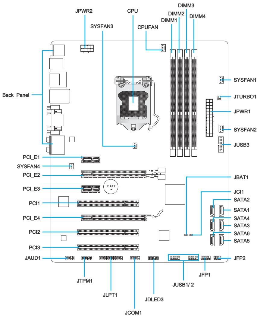
Connectors Reference Guide
| Port Name | Port Type | Page |
| Back Panel | I/O Ports | En-6 |
| CPU | LGA 1155 CPU Socket | En-9 |
| CPUFAN,SYSFAN1~4 | Fan Power Connectors | En-18 |
| DIMM1~4 | DDR3 Memory Slots | En-14 |
| JAUD1 | Front Panel Audio Connector | En-22 |
| JBAT1 | Clear CMOS Jumper | En-25 |
| JCI1 | Chassis Intrusion Connector | En-21 |
| JCOM1 | Serial Port Connector | En-23 |
| JDLED3 | Voice Genie Connector | En-24 |
| JFP1, JFP2 | Front Panel Connectors | En-19 |
| JLPT1 | Parallel Port Connector | En-23 |
| JPWR1 | ATX 24-pin Power Connector | En-13 |
| JPWR2 | ATX 8-pin Power Connector | En-13 |
| JTPM1 | TPM Module Connector | En-22 |
| JTURBO1 | MultiConnect Panel Connector | En-24 |
| JUSB1~2 | USB 2.0 Expansion Connectors | En-21 |
| JUSB3 | USB 3.0 Expansion Connector | En-20 |
| PCI_E1, E3 | PCIe x1 Expansion Slots | En-16 |
| PCI_E2, E4 | PCIe x16 Expansion Slots | En-16 |
| PCI1~3 | PCI Expansion Slots | En-16 |
| SATA1~6 | SATA Connectors | En-17 |
Back Panel Quick Guide
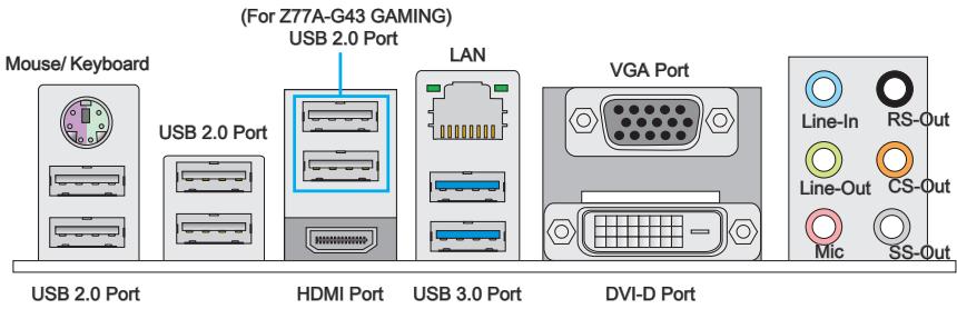
Mouse/Keyboard
A combination PS/2® mouse/keyboard DIN connector for a PS/2® mouse/keyboard.
USB 2.0 Port
The USB 2.0 port is for attaching USB 2.0 devices such as keyboard, mouse, or other USB 2.0-compatible devices.
USB 3.0 Port
USB 3.0 port is backward-compatible with USB 2.0 devices. It supports data transfer rate up to 5 Gbit/s (SuperSpeed).

Important
In order to use USB 3.0 devices, you must connect to a USB 3.0 port. If a USB cable is used, it must be USB 3.0 compliant.
LAN
The standard RJ-45 LAN jack is for connecting to a Local Area Network (LAN).
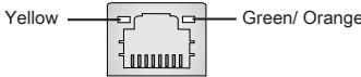
| LED | Color | LED State | Condition |
| Left | Yellow | Off | LAN link is not established. |
| On(Steady) | LAN link is established. | ||
| On(FLASHING) | The computer is communicating with another computer on the network. | ||
| Right | Green | Off | 10 Mbits/sec data rate |
| On | 100 Mbits/sec data rate | ||
| Orange | On | 1000 Mbits/sec data rate |
> HDMI Port
HOMI
HIGH-DEFINITION MULTIMEDIA INTERFACE
The High-Definition Multimedia Interface (HDMI) is an all-digital audio-video interface that is capable of transmitting uncompressed streams. HDMI supports all types of TV formats, including standard, enhanced, or high-definition video, plus multi-channel digital audio on a single cable.
VGA Port
The DB15-pin female connector is provided for monitor.
> DVI-D Port
The DVI-D (Digital Visual Interface-Digital) connector can be connected to a LCD monitor, or a CRT monitor with an adapter. To connect a monitor, please refer to the monitor's manual for more information.

Important
This motherboard supports dual-display function by any two output ports (HDMI+DVI-D, DVI-D+VGA or VGA+HDMI).
| HDMI+DVI-D | DVI-D+VGA | VGA+HDMI | |
| Extend mode (Extend the desktop to the second monitor) | ○ | ○ | ○ |
| Clone mode (Two monitors have the same screen) | ○ | ○ | ○ |
Audio Ports
These connectors are used for audio devices. The color of the jack refers to the function of the connector.
Blue-Line in: Used for connecting external audio outputting devices.
- Green- Line out: Used as a connector for speakers or headphone.
Pink-Mic:Used as a connector for a microphone.
- Black- RS-Out: Rear surround sound line out in 4/5.1/7.1 channel mode.
Orange-CS-Out: Center/subwoofer line out in 5.1/7.1 channel mode.
Gray-SS-Out:Side surround sound line out in 7.1 channel mode.
CPU (Central Processing Unit)
Introduction to the LGA 1155 CPU
The surface of the LGA 1155 CPU has two alignment keys and a yellow triangle to assist in correctly lining up the CPU for motherboard placement. The yellow triangle is the Pin 1 indicator.
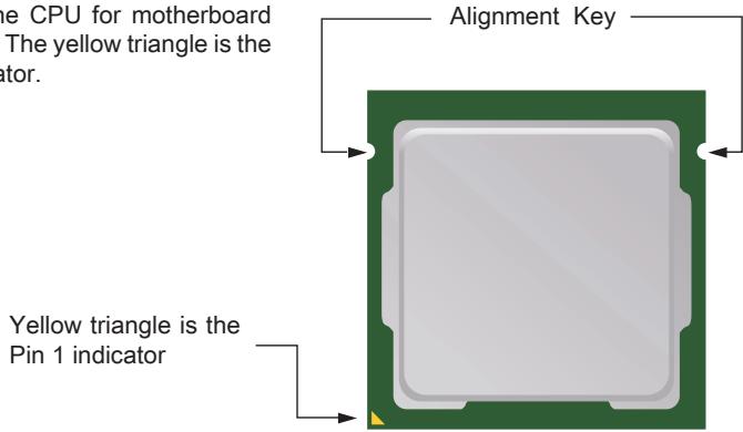

Important
Overheating
Overheating can seriously damage the CPU and motherboard. Always make sure the cooling fans work properly to protect the CPU from overheating. Be sure to apply an even layer of thermal paste (or thermal tape) between the CPU and the heatsink to enhance heat dissipation.
Replacing the CPU
When replacing the CPU, always turn off the system's power supply and unplug the power supply's power cord to ensure the safety of the CPU.
Overclocking
This motherboard is designed to support overclocking. Before attempting to overclock, please make sure that all other system components can tolerate overclocking. Any attempt to operate beyond product specifications is not recommend. MSI does not guarantee the damages or risks caused by inadequate operation beyond product specifications.
CPU & Cooler Installation
When installing a CPU, always remember to install a CPU cooler. A CPU cooler is necessary to prevent overheating and maintain system stability. Follow the steps below to ensure correct CPU and CPU cooler installation. Wrong installation can damage both the CPU and the motherboard.
- Unhook and lift the loading lever to the fully open position.
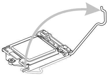
- Line up the CPU to fit the CPU socket. Be sure to hold the CPU by the base with the metal contacts facing downward. The alignment keys on the CPU will line up with the edges of the CPU socket to ensure a correct fit.

- The loading plates should automatically lift up as the loading lever is pushed to the fully open position. Do not touch any of the CPU socket pins.
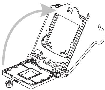
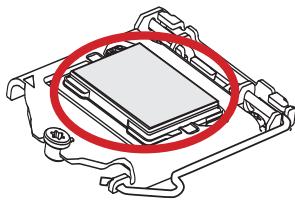
- Close the loading plate and remove the plastic protective cap.
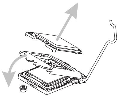
- Inspect the CPU to check if it is properly seated in the socket. Press the loading lever down and lock it under the retention tab.

- Locate the CPU fan connector on the motherboard.
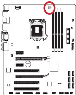
- Evenly spread a thin layer of thermal paste (or thermal tape) on the top of the CPU. This will help in heat dissipation and prevent CPU overheating.
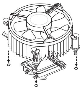
- Place the heatsink on the motherboard with the fan's wires facing towards the fan connector and the hooks matching the holes on the motherboard.
- Push down on the heatsink until the four clips get wedged into the holes on the motherboard. Press the four hooks down to fasten the cooler. As each hook locks into position a click should be heard.
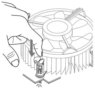
- Inspect the motherboard to ensure that the clip-ends have been properly locked in place.

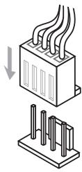
- Finally, attach the CPU fan cable to the CPU fan connector on the motherboard.

Important
- Do not touch the CPU socket pins.
- Confirm that the CPU cooler has formed a tight seal with the CPU before booting your system.
- Whenever the CPU is not installed, always protect the CPU socket pins by covering the socket with the plastic cap.
- Please refer to the documentation in the CPU cooler package for more details about CPU cooler installation.
Mounting Screw Holes
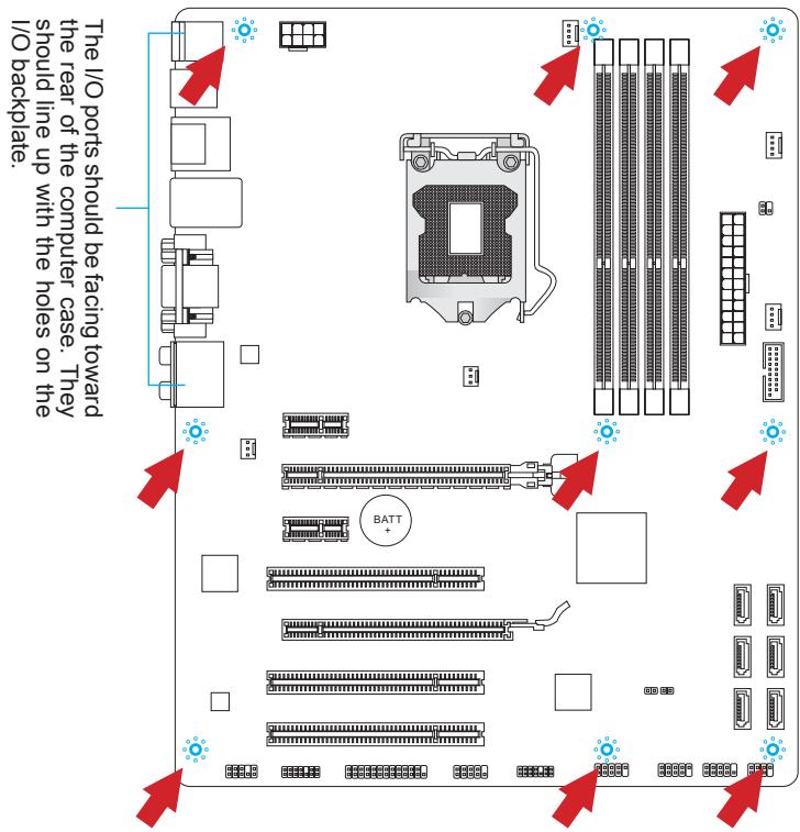
When installing the motherboard, first install the necessary mounting stands required for a motherboard on the mounting plate in your computer case. If there is an I/O back plate that came with the computer case, please replace it with the I/O backplate that came with the motherboard package. The I/O backplate should snap easily into the computer case without the need for any screws. Align the mounting plate's mounting stands with the screw holes on the motherboard and secure the motherboard with the screws provided with your computer case. The locations of the screw holes on the motherboard are shown below. For more information, please refer to the manual that came with the computer case.

Important
- Install the motherboard on a flat surface free from unnecessary debris.
- To prevent damage to the motherboard, any contact between the motherboard circuitry and the computer case, except for the mounting stands, is prohibited.
- Please make sure there are no loose metal components on the motherboard or within the computer case that may cause a short circuit of the motherboard.
Power Supply
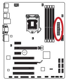
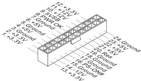
JPWR1:ATX24-pinPowerConnector
This connector allows you to connect an ATX 24-pin power supply. To connect the ATX 24-pin power supply, align the power supply cable with the connector and firmly press the cable into the connector. If done correctly, the clip on the power cable should be hooked on the motherboard's power connector.

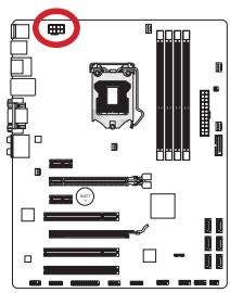
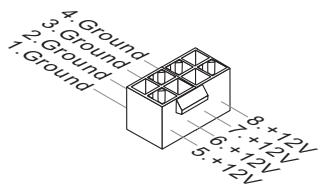
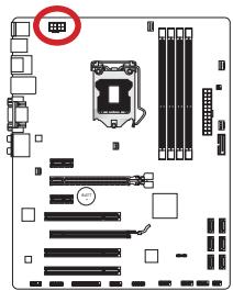
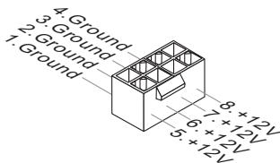
JPWR2:ATX8-pinPowerConnector
This connector provides 12V power to the CPU.

Important
Make sure that all the power cables are securely connected to a proper ATX power supply to ensure stable operation of the motherboard.
Memory
These DIMM slots are used for installing memory modules. For more information on compatible components, please visit http://www.msi.com/service/test-report/
DDR3
240-pin, 1.5V

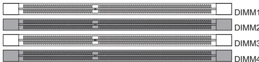
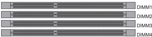
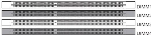
Dual-Channel mode Population Rule
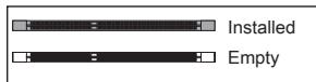
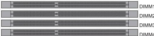
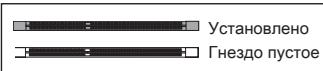
In Dual-Channel mode, the memory modules can transmit and receive data with two data bus channels simultaneously. Enabling Dual-Channel mode can enhance system performance. The following illustrations explain the population rules for Dual-Channel mode.
①
2

Important
- DDR3 memory modules are not interchangeable with DDR2, and the DDR3 standard is not backward compatible. Always install DDR3 memory modules in DDR3 DIMM slots.
- To ensure system stability, memory modules must be of the same type and density in Dual-Channel mode.
- Due to chipset resource usage, the system will only detect up to 31+ GB of memory (not full 32 GB) when all DIMM slots have 8GB memory modules installed.
Installing Memory Modules
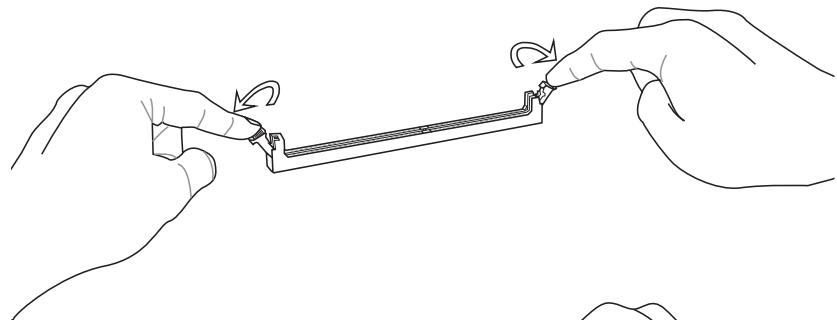
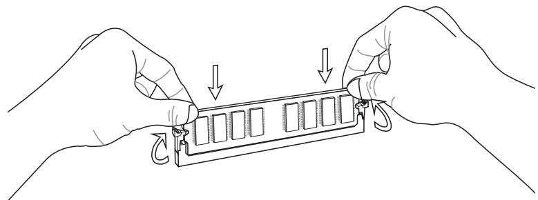
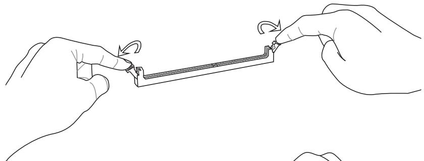
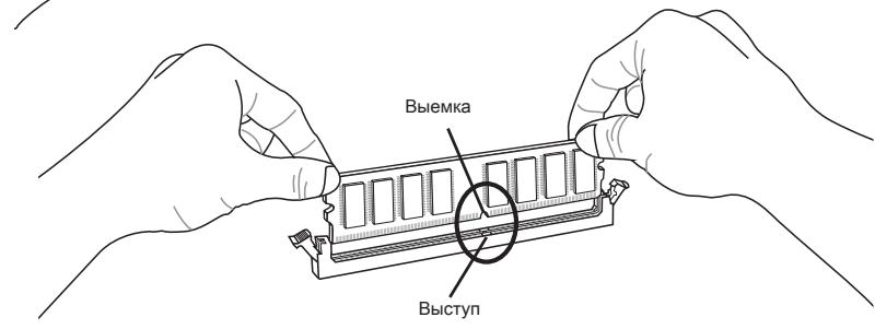
- Unlock the DIMM slot by pushing the mounting clips to the side. Vertically insert the memory module into the DIMM slot. The memory module has an off-center notch on the bottom that will only allow it to fit one way into the DIMM slot.
- Push the memory module deep into the DIMM slot. The plastic clips at each side of the DIMM slot will automatically close when the memory module is properly seat and an audible click should be heard.
- Manually check if the memory module has been locked in place by the DIMM slot's side clips.

Expansion Slots
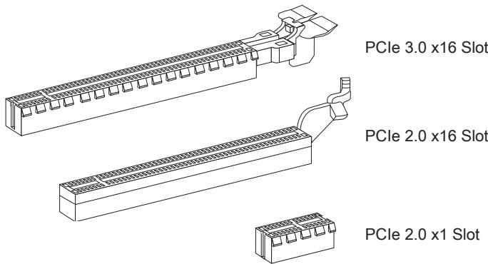
This motherboard contains numerous ports for expansion cards, such as discrete graphics or audio cards.
PCIe Expansion Slot
The PCIe slot supports the PCIe interface expansion card.
PCI Expansion Slot
The PCI slot supports additional LAN, SCSI, USB, and other add-on cards that comply with PCI specifications.
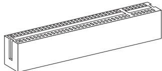
32-bit PCI Slot

Important
When adding or removing expansion cards, always turn off the power supply and unplug the power supply power cable from the power outlet. Read the expansion card's documentation to check for any necessary additional hardware or software changes.
PCI Interrupt Request Routing
IRQ, or interrupt request lines, are hardware lines over which devices can send interrupt requests to the processor. The PCI IRQ pins are typically connected to the PCI bus pins as followed:
| Order1 | Order2 | Order3 | Order4 | |
| PCI Slot1 | INT A# | INT B# | INT C# | INT D# |
| PCI Slot2 | INT B# | INT C# | INT D# | INT A# |
| PCI Slot3 | INT C# | INT D# | INT A# | INT B# |
Internal Connectors
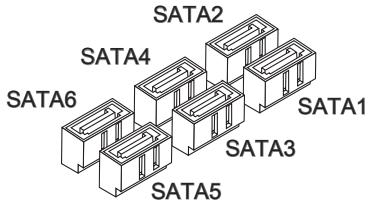
SATA1~6: SATA Connectors
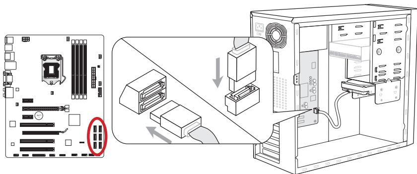
This connector is a high-speed SATA interface port. Each connector can connect to one SATA device. SATA devices include disk drives (HDD), solid state drives (SSD), and optical drives (CD/DVD/Blu-Ray).
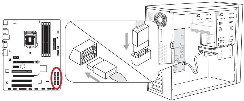
* The MB layout in this figure is for reference only.
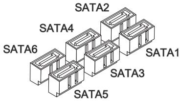
SATA1~2 (6Gb/s), SATA3~6 (3Gb/s) (Z77A-G43 GAMING)
SATA1 (6Gb/s), SATA2~6 (3Gb/s) (B75A-G43 GAMING)

Important
- Many SATA devices also need a power cable from the power supply. Such devices include disk drives (HDD), solid state drives (SSD), and optical drives (CD / DVD / Blu-Ray). Please refer to the device's manual for further information.
- Many computer cases also require that large SATA devices, such as HDDs, SSDs, and optical drives, be screwed down into the case. Refer to the manual that came with your computer case or your SATA device for further installation instructions.
- Please do not fold the SATA cable at a 90-degree angle. Data loss may result during transmission otherwise.
- SATA cables have identical plugs on either sides of the cable. However, it is recommended that the flat connector be connected to the motherboard for space saving purposes.
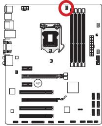
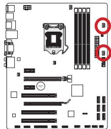
CPUFAN,SYSFAN1~4: Fan Power Connectors
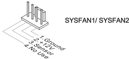
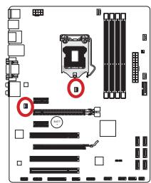
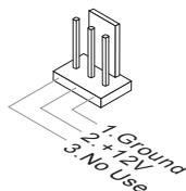
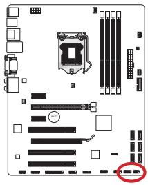
The fan power connectors support system cooling fans with +12V. If the motherboard has a System Hardware Monitor chipset on-board, you must use a specially designed fan with a speed sensor to take advantage of the CPU fan control. Remember to connect all system fans. Some system fans may not connect to the motherboard and will instead connect to the power supply directly. A system fan can be plugged into any available system fan connector.
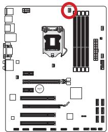
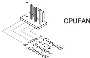
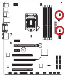
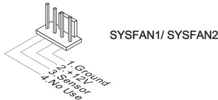
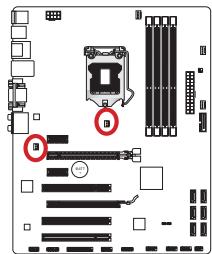
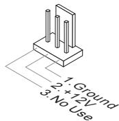
SYSFAN3/ SYSFAN4

Important
- Please refer to your processor's official website or consult your vendor to find recommended CPU cooling fans.
- The CPUFAN, SYSFAN1, SYSFAN2 connectors support Smart Fan Control with liner mode. The Control Center II utility can be installed to automatically control the fan speeds according to the CPU's and system's temperature.
- If there are not enough ports on the motherboard to connect all system fans, adapters are available to connect a fan directly to a power supply.
- Before first boot up, ensure that there are no cables impeding any fan blades.
JFP1, JFP2: Front Panel Connectors
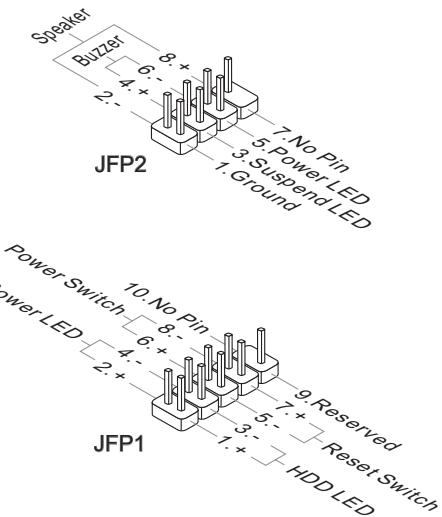
These connectors connect to the front panel switches and LEDs. The JFP1 connector is compliant with the Intel® Front Panel I/O Connectivity Design Guide. When installing the front panel connectors, please use the optional mConnectors to simplify installation. Plug all the wires from the computer case into the mConnectors and then plug the mConnectors into the motherboard.
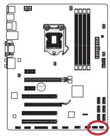
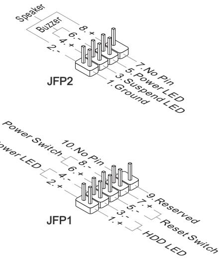

Important
- On the connectors coming from the case, pins marked by small triangles are positive wires. Please use the diagrams above and the writing on the mConnectors to determine correct connector orientation and placement.
- The majority of the computer case's front panel connectors will primarily be plugged into JFP1.
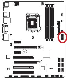
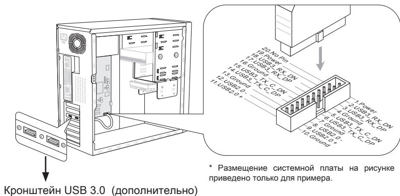
JUSB3: USB 3.0 Expansion Connector
The USB 3.0 port is backwards compatible with USB 2.0 devices. It supports data transfer rates up to 5Gbits/s (SuperSpeed).
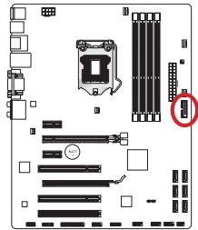


Important
- Note that the VCC and GND pins must be connected correctly to avoid possible damage.
- To use a USB 3.0 device, you must connect the device to a USB 3.0 port through an optional USB 3.0 compliant cable.
JUSB1~2: USB 2.0 Expansion Connector
This connector is designed for connecting high-speed USB peripherals such as USB HDDs, digital cameras, MP3 players, printers, modems, and many others.
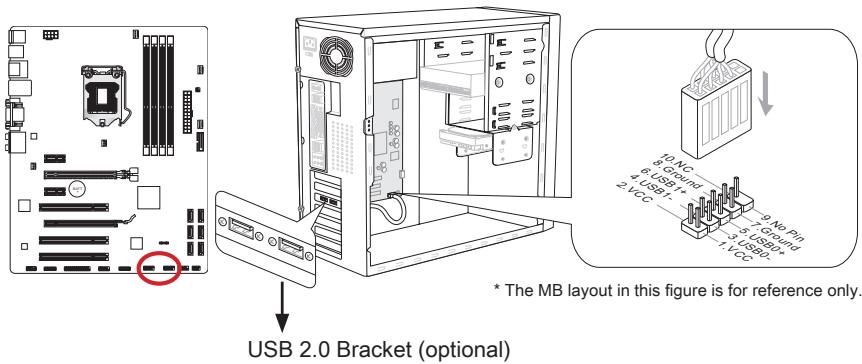

Important
Note that the VCC and GND pins must be connected correctly to avoid possible damage.
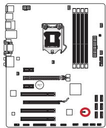
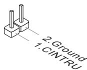
JCI1: Chassis Intrusion Connector
This connector connects to the chassis intrusion switch cable. If the computer case is opened, the chassis intrusion mechanism will be activated. The system will record this intrusion and a warning message will flash on screen. To clear the warning, you must enter the BIOS utility and clear the record.
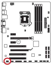
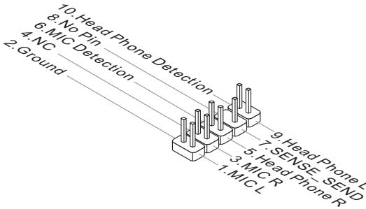
JAUD1: Front Panel Audio Connector
This connector allows you to connect the front audio panel located on your computer case. This connector is compliant with the Intel® Front Panel I/O Connectivity Design Guide.
JTPM1: TPM Module Connector
This connector connects to a TPM (Trusted Platform Module). Please refer to the TPM security platform manual for more details and usages.
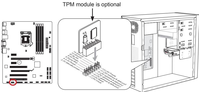
* The MB layout in this figure is for reference only.
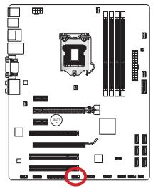
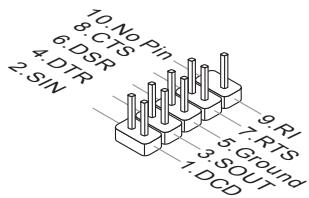
JCOM1: Serial Port Connector
This connector is a 16550A high speed communication port that sends/receives 16 bytes FIFOs. You can attach a serial device.
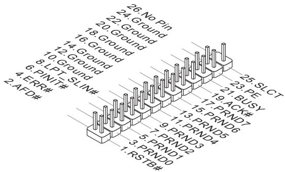
JLPT1: Parallel Port Connector
This connector is used to connect an optional parallel port bracket. The parallel port is a standard printer port that supports Enhanced Parallel Port (EPP) and Extended Capabilities Parallel Port (ECP) mode.

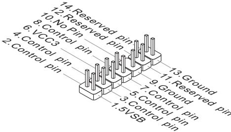
JDLED3: Voice Genie Connector (optional)
This connector is used to link to the voice control module (optional). Please refer to its user guide for more details and usages.

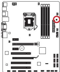
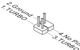
JTURBO1: MultiConnect Panel Connector (optional)
This connector is used to connect an optional front panel for controlling the OC Genie and some additional functions. Please refer to its user guide for more details and usages.
Jumper
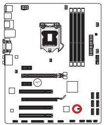
JBAT1: Clear CMOS Jumper
There is CMOS RAM onboard that is external powered from a battery located on the motherboard to save system configuration data. With the CMOS RAM, the system can automatically boot into the operating system (OS) every time it is turned on. If you want to clear the system configuration, set the jumpers to clear the CMOS RAM.

Keep Data

Clear Data

Important
You can clear the CMOS RAM by shorting this jumper while the system is off. Afterwards, open the jumper. Do not clear the CMOS RAM while the system is on because it will damage the motherboard.
Drivers and Utilities
After you install the operating system you will need to install drivers to maximize the performance of the new computer you just built. MSI mainboard comes with a Driver Disc. Drivers allow the computer to utilize your motherboard more efficiently and take advantage of any special features we provide.
Total Installer
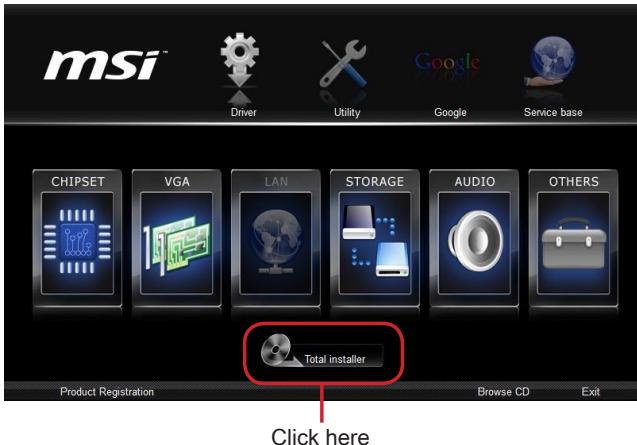
Total Installer is very easy to use and does a great job of finding necessary drivers. Please follow the steps below to install drivers and utilities for your new computer.
- Insert MSI Driver Disc into the optical drive. The setup screen will automatically appear if autorun is enabled in OS.
- Click Total Installer. A popup dialog will appear listing all necessary drivers.
- Select all checkbox on driver listing dialog.
- Click Install button.
- The software installation will then be in progress, after it has finished it will prompt you to restart.
- Click OK button to finish.
- Restart your computer.
You can also use the same method to install the utilities.

Important
The picture above is for reference only and may vary from the product you purchased. Please refer to the actual screens of your system for detailed information.
BIOS Setup
CLICK BIOS II is developed by MSI that provides a graphical user interface for setting parameters of BIOS by using the mouse and the keyboard.
With the CLICK BIOS II, users can change BIOS settings, monitor processor temperature, select the boot device priority and view system information such as the processor name, DRAM capacity, the OS version and the BIOS version. Users can import and export parameters data for backup or sharing with friends. After connecting to Internet, users can browse the internet, check mail and live update your system.
Entering
Power on the computer and the system will start POST (Power On Self Test) process. When the message below appears on the screen, press key to enter Setup.
Press DEL key to enter Setup Menu, F11 to enter Boot Menu
If the message disappears before you respond and you still wish to enter Setup, restart the system by turning it OFF and On or pressing the RESET button. You may also restart the system by simultaneously pressing <Ctrl> , <Alt> , and <Delete> keys.

Important
The items under each BIOS category described in this section are under continuous update for better system performance. Therefore, the description may be slightly different from the latest BIOS and should be held for reference only.
Overview
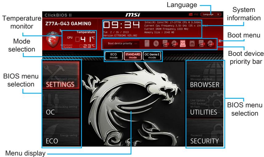
After entering Click BIOS II, the following screen is displayed.

Important
The pictures in this guide are for reference only and may vary from the product you purchased. Please refer to the actual screens of your system for detailed information.
Temperature monitor
This block shows the temperature of the processor and the motherboard.
System information
This block shows the time, date, CPU name, CPU frequency, DRAM frequency, DRAM capacity and the BIOS version.
BIOS menu selection
These blocks are used to select menus of BIOS. The following options are available:
- SETTINGS - Use this menu to specify your settings for chipset features, boot device.
- OC - This menu contains items of the frequency and voltage adjustments. Increasing the frequency can get better performance, however high frequency and heat can cause instability, we do not recommend general users to overclock.
ECO - This menu is related to energy-saving settings. - BROWSER - This feature is used to enter the MSI Winki web browser.
- UTILITIES - This menu contains utilities for backup and update.
SECURITY - The security menu is used to keep unauthorized people from making any changes to the settings. You can use these security features to protect your system.
Boot device priority bar
You can move the device icons to change the boot priority.
Boot menu
This button is used to open a boot menu. Click the item to boot the system from the device instantly.
Mode selection
This feature allows you to load presets of energy saving or overclocking.
Menu display
This area provides BIOS settings and information to be configured.
Language
This allows you to select the language of the BIOS setting.
Boot device priority bar
This bar shows the priority of the boot devices. The lighted icons indicate that the devices are available.

Click and draw the icon to left or right to specify the boot priority.
Sub-Menu
If you find a point symbol to the left of certain fields, that means a sub-menu can be launched for additional options. You can use the arrow keys or mouse to highlight the field and press
General Help
The General Help screen lists the appropriate keys to use for navigation. You can call up this screen from any menu by simply pressing
Operation
CLICK BIOS II allows you to control BIOS settings with the mouse and the keyboard. The following table lists and describes the hot keys and the mouse operations.
| Hot key | Mouse | Description |
| <↑↓→←> | Move the cursor | Select Item |
| <Enter> | Click/ Double-click the left button | Select Icon/ Field |
| <Esc> | Click the right button | Jump to the Exit menu or return to the previous from a submenu |
| <++> | Increase the numeric value or make changes | |
| <-> | Decrease the numeric value or make changes | |
| <F1> | General Help | |
| <F4> | CPU Specifications | |
| <F5> | Enter Memory-Z | |
| <F6> | Load optimized defaults | |
| <F8> | OC Profile Load From USB drive | |
| <F9> | OC Profile Save to USB drive | |
| <F10> | Save Change and Reset | |
| <F12> | Save a screenshot to a FAT/FAT32 USB drive |
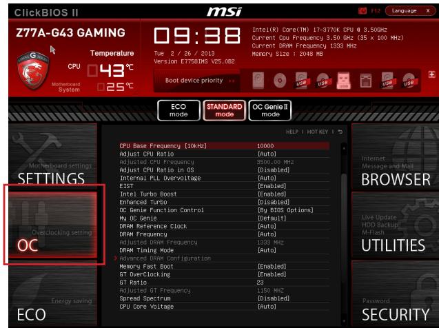
OC Menu
This menu is for advanced users who want to overclock the motherboard.

Important
- Overclocking your PC manually is only recommended for advanced users.
- Overclocking is not guaranteed, and if done improperly, can void your warranty or severely damage your hardware.
- If you are unfamiliar with overclocking, we advise you to use OC Genie for easy overclocking.
Current CPU/ DRAM Frequency
These items show the current clocks of CPU and Memory speed. Read-only.
CPU Base Frequency [10KHz]
Allows you to set the CPU Base clock (in 10KHz increments). You may overclock the CPU by adjusting this value. Please note that overclocking behavior and stability is not guaranteed.
Adjust CPU Ratio
Controls the multiplier that is used to determine internal clock speed of the processor. This feature can only be changed if the processor supports this function.
Adjusted CPU Frequency
It shows the adjusted CPU frequency. Read-only.
Adjust CPU Ratio in OS
Enable this item to allow CPU ratio changes in the OS by using MSI Control Center II.
Internal PLL Overvoltage
This item is used to adjust the PLL voltage.
EIST
Enhanced Intel SpeedStep technology allows you to set the performance level of the microprocessor whether the computer is running on battery or AC power. This field only appears with installed CPUs that support this technology.
Intel Turbo Boost
Enables or disables Intel Turbo Boost which automatically boosts CPU performance above rated specifications (when applications requests the highest performance state of the processor).
Enhanced Turbo
[Enabled] All CPU cores would be increased to Intel maximum turbo boost ratio.
[Disabled] Disable this function.
OC Genie Function Control
This item allows you to enable/disable the OC Genie function.
My OC Genie
This item is used to select whether OC Genie parameters are customized by user.
[Default] OC Genie will use default OC related parameters to overclock the system.
[Customize] Allows user to configure the following related "My OC Genie option" submenu manually for OC Genie.
DRAM Reference Clock
This item appears when a CPU that supports this adjustment is installed. This item allows user to set the DRAM reference clock.
DRAM Frequency
This item allows you to adjust the DRAM frequency. Please note the overclocking behavior is not guaranteed.
Adjusted DRAM Frequency
It shows the adjusted DRAM frequency. Read-only.
DRAM Timing Mode
Select whether DRAM timing is controlled by the SPD (Serial Presence Detect) EEPROM on the DRAM module. Setting to [Auto] enables DRAM timings and the following "Advanced DRAM Configuration" sub-menu to be determined by BIOS based on the configurations on the SPD. Selecting [Link] or [Unlink] allows users to configure the DRAM timings for each channel and the following related "Advanced DRAM Configuration" sub-menu manually.
Advanced DRAM Configuration
Press
Memory Fast Boot
This item is used to enable/disable Memory Fast Boot.
GT OverClocking
This item allows you to enable/ disable the overclocking of integrated graphics.
GT Ratio
This setting controls the ratio of integrated graphics frequency to enable the integrated graphics to run at different frequency combinations.
Adjusted GT Frequency
It shows the adjusted integrated graphics frequency. Read-only.
Spread Spectrum
This function reduces the EMI (Electromagnetic Interference) generated by modulating clock generator pulses.

Important
- If you do not have any EMI problem, leave the setting at [Disabled] for optimal system stability and performance. But if you are plagued by EMI, select the value of Spread Spectrum for EMI reduction.
- The greater the Spread Spectrum value is, the greater the EMI is reduced, and the system will become less stable. For the most suitable Spread Spectrum value, please consult your local EMI regulation.
- Remember to disable Spread Spectrum if you are overclocking because even a slight jitter can introduce a temporary boost in clock speed which may just cause your overclocked processor to lock up.
CPU Core Voltage/ DRAM Voltage.
These items are used to adjust the voltages.
Current CPU Core Voltage/ Current DRAM Voltage
These items show current voltages. Read-only.
OC Retry Count
This item is used to set the number of booting times with the present over-clocking settings. If over-clocking has failed with the designated booting times, the system will restore the defaults at next boot.
Overclocking Profiles
Press
Overclocking Profile 1/2/3/4/5/6
Press
OC Profile Save to USB
Set Name for Overclocking Profile 1/2/3/4/5/6
Give a name by typing in this item.
Save Overclocking Profile 1/2/3/4/5/6
Save the current overclocking settings to ROM for selected profile.
Load/ Clear Overclocking Profile 1/2/3/4/5/6
Load/ Clear the stored profile settings from ROM.
Save the current overclocking settings to USB flash disk.
OC Profile Load from USB
Load the stored settings from USB flash disk.
CPU Specifications
Press
CPU Technology Support
Press
MEMORY-Z
Press
DIMM1~4 Memory SPD
Press
CPU Features
Press
Hyper-Threading Technology
The processor uses Hyper-Threading technology to increase transaction
rates and reduces end-user response times. Intel Hyper-Threading technology treats the multi cores inside the processor as multi logical processors that can execute instructions simultaneously. In this way, the system performance is highly improved.
[Enable] Enable Intel Hyper-Threading technology.
[Disabled] Disable this item if your operating system does not support HT function.
Active Processor Cores
This item allows you to select the number of active processor cores.
Limit CPUID Maximum
It is designed to limit the listed speed of the processor to older operating systems.
Execute Disable Bit
Can prevent certain classes of malicious "buffer overflow" attacks where worms can try to execute code to damage your system. It is recommended you keep this enabled always.
Intel Virtualization Tech
Enhances virtualization and allows the system to act as multiple virtual systems. See Intel's official website for more information.
Intel VT-D Tech
This item is used to enable/disable the Intel VT-D technology. For further information please refer to Intel's official website.
Hardware Prefetcher
Enable or disable the hardware prefetcher of CPU.
[Enabled] Allows the CPU hardware prefetcher to automatically pre-fetch data and instructions from memory into L2 cache for reducing the latency time associated with memory reads.
[Disabled] Disable the CPU hardware prefetcher.
>Adjacent Cache Line prefetch
Enable or disable the CPU hardware prefetcher to pre-drop the adjacent cache line.
[Enabled] Allows the CPU hardware prefetcher to automatically pre-drop an available cache line for reducing the cache latency time.
[Disabled] CPU will only fetch the requested cache line.
Power Technology
This item allows you to select the Intel Dynamic Power technology mode.
C1E Support
Enable system to reduce CPU power consumption while idle. Not all processors support Enhanced Halt state (C1E).
OverSpeed Protection
Monitors current CPU draw as well as power consumption; if it exceeds a certain level, the processor automatically reduces its clock speed. For overclocking, it is recommended to disable this filed.
Intel C-State
C-state is a power management state that detects when the system is idle and lowers power consumption accordingly.
Package C State limit
This field allows you to select a C-state mode.
> Long duration power limit (W)
This field allows you to adjust the TDP power limit for the long duration.
> Long duration maintained (s)
This field allows you to adjust the maintaining time for long duration power limit.
> Short duration power limit (W)
This field allows you to adjust the TDP power limit for the short duration.
Primary/ Secondary Plane Current value (A)
These fields allow you to adjust over current value of CPU (primary plane)/ iGPU (secondary plane) for turbo ratio.
Primary/ Secondary plane turbo power limit (W)
These fields allow you to adjust the turbo power limit of CPU (primary plane)/ iGPU (secondary plane) for turbo boost.
1/2/3/4-Core Ratio Limit
These items only appear when a CPU that support this function is installed. These items allow you to set the CPU ratios in different active cores in turbo boost mode.
Updating the BIOS with Live Update
This section tells you how to update the BIOS by using the Live Update utility before entering Operating System. Live Update will update the BIOS automatically when connecting to the Internet. To update the BIOS with the Live Update utility:
- Click Live Update button installed).

on the BIOS UTILITIES menu. (The Winki must be
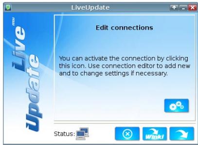
- Setup the connection by click the setting button if necessary.
- Click the next button
- Live Update will automatically detect the version of BIOS and download the appropriate file.
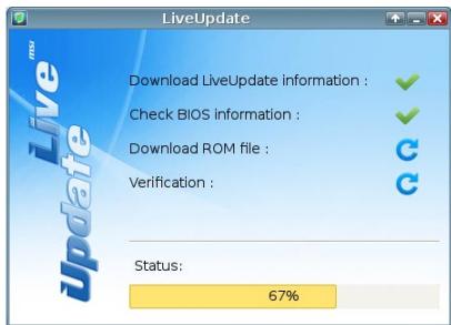
- Click the confirm button

to update the BIOS.


Do not update the BIOS if your system is running fine.
This section describes how to install Windows XP with IDE or AHCI mode.
Installing Windows XP with IDE Mode
You will fail and encounter a blue screen while installing Windows XP, because it is not natively supported to be installed in the storage device with AHCI mode. If you still prefer to install Windows XP as the operating system, please change the BIOS item as below.
- Refer to Chapter 2 to access BIOS.
- Go to SETTINGS Integrated Peripherals SATA Mode.
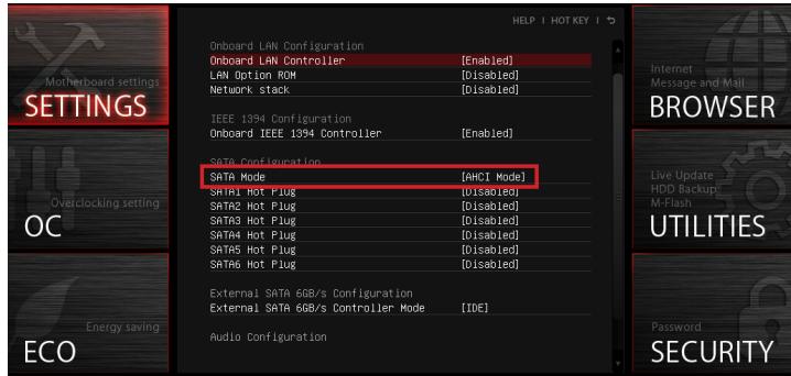
- Set this item to IDE mode.
- Go to SETTINGS Save & Exit Save changes and reboot.
- Install the Windows XP operating system.
Installing Windows XP with AHCI Mode
If you prefer to install Windows XP as the operating system with AHCI mode, please prepare AHCI drivers for Windows XP in advanced.
Creating a Intel AHCI Driver Disc
Please follow the instruction below to make an "AHCI Driver" for yourself.
Insert the MSI DVD into the DVD-ROM drive.
- Click the "Browse CD" on the Setup screen.
- Copy all the contents from \Storage\Intel\PCH 7\f6fly-x86 or f6fly-x64 to a formatted floppy diskette.
The driver diskette is done.

Important
You can download the driver from
http://download3.msi.com/files/downloads/dvrexe/intel7x_rst_floppy_mb.zip
Installing the Windows XP Operating System:
Please follow the below steps:
- Access BIOS, set SATA Mode to AHCI mode, save, exit and reboot.
- Ensure the USB Floppy Disk Drive is connected to the computer.
- Install Windows XP. When Windows Setup screen appears a message "Press F6 if you need to install a third party SCSI or RAID driver..., press "F6" key.
- Insert the floppy disk containing the AHCI drivers into the floppy disk drive.
- When the next screen appears, press the "S" key to specify an additional device.
- From the provided list, select the Intel(R) 7 Series SATA AHCI Controller.
- Follow the on-screen instructions to complete the installation.

Deutsch
Z77A-G43 GAMING/
B75A-G43 GAMING
Serie
Spezifikationen
Prozessoren
Die Intel® Core™ i7/ Core™ i5/ Core™ i3/ Pentium®/ Celeron® der 3. Generation für LGA 1155 Sockel
Chipsatz
http://www.msi.com/service/cpu-support/

JFP1, JFP2: Frontpanel Anschlüsse
Current CPU/ DRAM Frequency
Adjusted CPU Frequency
Adjust CPU Ratio in OS
Adjusted GT Frequency
OC Retry Count
CPU Technology Support
Active Processor Cores
Intel Virtualization Tech
>Adjacent Cache Line prefetch
OverSpeed Protection
Package C State limit
> Long duration power limit (W)
> Long Duration Maintained (s)
Primary/ Secondary Plane Current value (A)
Primary/ Secondary plane turbo power limit (W)
4x ports USB 2.0 (B75A-G43 GAMING)
Drivers and Utilities
CPU Base Frequency [10KHz]
Adjusted CPU Frequency
Adjust CPU Ratio in OS
Adjusted DRAM Frequency
Adjusted GT Frequency
Current CPU Core Voltage/ Current DRAM Voltage
OC Retry Count
CPU Technology Support
[Active] Active la technologie Intel Hyper-Threading.
Active Processor Cores
Intel Virtualization Tech
Adjacent Cache Line Prefetch
OverSpeed Protection
Package C State limit
Long duration power limit (W)
Long duration maintained (s)
Short duration power limit (W)
Primary/ Secondary Plane Current value (A)
Primary/ Secondary plane turbo power limit (W)
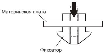
- Ocmotpnte MaTePNHcky IpaTy nOppeJeNTe npaBnIbHOCTb 3aKpenJIeHnI 3aJIMOB.
11.И,нakoneц,поклочи КабьВERTNЯTOPA npoceccopa Kpa3bemyBEHTNIATOPA Ha cnCTeMHOn ПаTe.

BhimaHue
- He tporaTe KOHTaKtIy UcTaHOBoUHoi nAHeNn npOceccopa.
- Пелед загузков системы поверътегрметуновсь coeиненя мжду поцec-copом и вентлитором.
- Ecnn npoueccop He yctaHOBJIe, 3aunuauTe KOHTaKTBI yCTaHOBOUHOn naHeIN npouecoppa nlaactNKOBbIM KONNaYCOM.
-Подрбhoe onuscaHne yctaHOBKn BeHTnIaTopa OxlaJdeHna Ipoceccopa CM.ВdoKymeHTaunB daHHOMy BeHTnIaTopy.
OTBepCTNIOyUcTaHOBOUHbIe BnHTbl
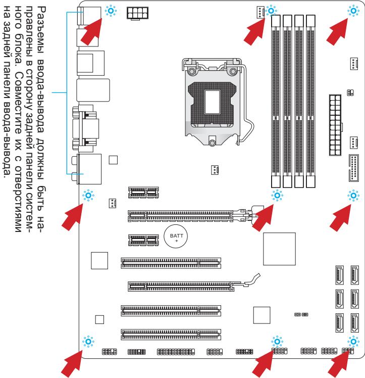
Для установки MaTePNHCKOи паы Ha моТахнOHи паTe СИСТЕМНОг 6нoka ChaЧапа YCTAHOBNTe Heo6xODmblcye UCTaHOBOUHbIe CToKn. EcIn B KOMPNeKT NOCTABKN CnCTEMHORO 6NOKA BXODIT 3aDnЯ NaHEn bBODa-BbIBOda,ЗamEHNTe ee 3aDнeЯ пaHelen bBOIDA-BbIBOda,КOTOPa NOCTABJnEtcrC MATEPNHCKOи pAnToI. 3aDnЯ NaHEn bBOIDA-BbIBOda 6e3 Tpya yCTaHaBJIbAeTcR C NCTEMHom 6NoKE KOMNbIOtepa 6e3 npImeHENBAHTOB.COBMeCTITE UCTaHOBOUHbIe CToKn MOtAZHNOI pAnTbIC OTBepCTnAryMn IOd yCTaHOBOUHbIe BnHTbI Ha MaTePNHCKOи пaTe n 3aKpeNITe MaTePNHCKy OIIaTy BnHTAMi, KOTOpBe NOCTABJIYOTcBMeTe C NCTeMhBlm 6NoKOM.HnKe NOKa3aHo paCnONJOKHeNE OTBepCTn IOd yCTaHOBOUHbIe BnHTbl.ДоПОЛНТeNBHy INФОрMaцINOM.C.BpyKOBOIDCTBE K CnCTeMHOMy 6NoKy.

BhimhaHue
-ПложinteMatepeHnckyIиЯТуHaPoBHyIuNCHCTyIO NOBepXHOCTb.
Bo n36eKaHne NOBpExKeHnMaTePHNCKoI PnAToI, 3aKpeJIyTe 3JeKToHHbIe KOMHOHeHTbHa yCTaHOBOUhIX CToiKaX, n36eRa Ix COpnKOCHOBeHn C CNTeMHbIM bJIOKOM.
- PnoBepbTe HadeXHocTb KpeIeHnB CEx MTeAIIuYeCKNX KOMNoHErTOB Ha MaTePnHcKo nnate nnn BHyTpN CnCTeMHoro 6Ioka. He3akpenIeHHbIe DeTaII N MoryT npNBecTI K KOpOTKOMy 3aMbKaHnIO MaTePHckO nnAtbl.
3JIeKTpOnnTaHne
JPWR1: 24-KoHTaKTbIpa3bem NITaHnA TX
3TOT pa3bem npedha3nueH nIe pOdkloueHn 24-koHTaKTHORo 6Joka nITaHnA ATX. IJIpe OOKNIOUeHn 6JOKa NITAHN AXT C 24-KoHTaKTHbIM pa3bEMOM COBMeCTInTe Ka6ebN PNTAHN C pa3bEMOM IN POUHO 3aKePENITE erO. Ipr npabINbHOM BbINOJIHeHn POKNIOUeHn 3aJeIka Ha Ka6eNe PNTAHN 3aKePENIErTcB CINOBom pa3bEme MaTePNHCKOIIaTbl.

JPWR2: 8-koHTaKThbI pa3bem nTahnA TX
3ToT pa3bem o6ecneuBaet noauly 12 B nItaHnHa npoceccop.

BhimaHue
IЯ obecneueHn ctabnBho paobt CNTeMHo nIaIb npOBepbTe HaedKHOCTb NOkHouHn Bcex KaBeNeu NHTAHN K COOTBETCTByOHeMy bNOky NtAHnA ATX.
NamrTa
3Tn rHe3da DIMM npedHa3NaueHbI dny yctaHOBKn MoyJeN pAmrIn. POpobHyu INΦopMaunO COBmecTmblx KOMNoHEtax CM. Ha caIte http://www.msi.com/service/test-report
Modynn namrtn
DDR3
240-KOHTAKTOB,1.5B

IpaBnla 3aOpHHeHn rHe3d npn nCNoJIb3OBAHn DByXKaHaNbHoropexima Dual-Channel
B dBvXkHaHbHom pexKMe moDyIi naMRTn mOryT oNHOpeMeHHo nepeDaBaTb n noLnyaT bAnHbIe no Dvym kHaIam shHb. BKnUoyHeNe DByXkHaHbHoro pexIma DualChannel moKet nobicntb npOn3BoNTeJbHoCTb cnCTeMb. Ha pncyHKax hNke nokazahbl npabInla 3anOpJIHeHn rHe3d nAmrTn npn IcNoJIb3OBaHN dByXkHaHbHoro pexIma Dual-Channel.
1
2

BHIMAHWE
- Moулл DDR3 He b3aunmo3amehЯEmbI c MoулЯMu DDR2, сандгт DDR3 He noДержиBaet obpaTHyO coBmecTUMocTb. Moулл NamTu DDR3 cneDyET yCTaHabЛиВaTb B rHe3da DDR3 DIMM.
- Д�� обесеньястабиьногюразовы СИСТЕМБВДБУХКАЛБНOM pexIMe yCTAHABJIBAHOTc MOYJIN namTn ONUHAKOBORO TUNA N EMKOCTN.
B CBa3n Co CneuФнКо NcNoJIb3OBAHnpeCypcoB MmKpOnpoeCCopa, npu yCTa-HOBKe MoUyIe namrTn EmKOctbIO 8 B0 Bce rHe3da DIMM cNCTemHa nAmrTo onpeJenEETc TOnbko Do 31+ B (HenoJIhble 32 B).
YCTaHOBka MOyJeI pAmrTn
- OToBnHbTe B CTOpOHy KInEMMbIe 3aXIMbI N OTKpoTte rHe3do DIMM. BepTnKaJIbHo BCTaBBte MoyIb IamrTu B rHe3do DIMM. B HnKHe yactu moyIa IamrTu ImeETc CMeueHHa OT cEHTrpa BbIeMka dIpy npabINbHO yCTaHOBKn MOnyIa B rHe3do DIMM.
- YctaHOBInTe MoUyIb NamrTn B rHe3do DIMM do ynpa. Ppi npabInbHom noJIOxHnn MoUyIa NamrTn B rHe3de pnaCTNKOBbIe 3aueKn C o6eNx CTopoHrHe3da DIMM aBtOMaTHueCKn 3aueJIKNBaIOTcN.
- Y6eIntecb, yTO MOyIb IamrTn 3aΦnKcnpoBaH B rHe3de DIMM 3aUeJIkAmn rHe3- da.

CLOTbI paCUnpeHnA
*Pa3MeueHne cIeTeMHo IaTbI Ha pncyHke npBedeHOToJbKO dJa npimepa.
SATA1~2 (6Γ6/c), SATA3~6 (3Γ6/c) (Z77A-G43 GAMING)
SATA1 (6Γ6/c), SATA2~6 (3Γ6/c) (B75A-G43 GAMING)

BHMHHe
Mhorme yctpoctBa SATA tpebyot nocknoyeneH K nctOunky nataHnC nomOuIbKabEJI nataHn. K taKIM yctpoCTBAM OTHOATcJXeCTKnE dNCK, TBePdTeNbIe HAKONITeNn HAKONITeNn Ha ONTuecknx DNCKAX (KOMNaKT-DNCKN/DVxD-Nck/Nu-Ray-Dnck). DOnonNTeNBHyIO INΦOpMaIIO MOXHO NOJyHTB BY PKOBOCTBAX K COOTBETCTBYUoIIM yCTPOCTBAM.
- Bo MHORIX cIcTeMhBix 6bokax yCtpoiCTBa SATA 6oJIbIoro pa3mepa (B TOM uNcIe, JcKTEH NDCIK, TBePdOteJIbHbIe HAKONITEN I HAKOHTEN I Na ONTueCKNX dNcCKAX) npKpeINJTOc C NMOUbIO BNTOB. DOnOIHNTeJIbHbIe INHCTpyKuIM NO yCTaHOBKe CM. B pyKoBOdCTBA K cIcTeMHomY 6bOKy UIny yCtpoiCTBy SATA.
- 136eata neperin60B ka6eTBA SATA noI nprrmbim yrnom. B npotnbom cnyae, BO3MOXHa nOtepra daHHbIX npn pepeaue.
KabennSATA OcnaeHbI OndaHKObIMn BuNkAMn C obEnx CTopoH. OndaHko Iyra KMOHOMIN 3aHmAmero npocTpaHCTBa peKOMeHdyETcra K MaTeepnHcOJ PNaTe POnKnIOu-aytb pnockn pa3bem.
CPUFAN,SYSFAN1~4:Pa3bemblNTaHnBBeHTNJIATOPOB
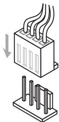
Pa3bEmbl nItaHnBEHTnIaTOPOB NOdEepXnBaOT BeHTnIaTObpC nITaHnEM +12 B. EcHn HcCTeMHoN pIaTe yctAHOBHeHa MMKPCxMeA nnapatHO rMOHToPnHra, Heo6XoJIMO hCNoIb3OaBt CneuAnhBHe BEHTnIaTOpC dTaYnKaMn CKOpOCTn DnI NCNOIb3OaHnry FyHKUYNpaBNeHNBEHTnIaTOpAMn. O63aTeNbHO NODKnIOHTe BCE cNCTeMHbE BHTnIaTOpB HeKOTOpBc NCTeMHbE BHTnIaTOpB HeBO3MOXKnHO DnIKJIOUYbHe K MaTePNHcOIN PNaTe.BMeCTO 3TOrO OHN NOkKnIOaOTcK N CTOHmky NITaHn HnPaMyO. BeHTnIaTOpB cNCTeMbI NODKnIOuaOTcK C Bo6OdHbIM pa3bEmam DnI BEHTnIaTOPOB.

SYSFAN3/ SYSFAN4

BHIMAHINE
I IJI NONYEHNBEHTINrAToPOB,peKOMeHDoBaHHbIXI JN OXJAAckJeHnI PPOeCCOPA, oBpaITNeCB HaOfUuHaNbHbI Be6-caIT npou3BoaUNTeNpOueCCOPA nn K MeCTHOMY NOCTABUcIKy.
Pa3bemblCPUFAN, SYSFAN1, SYSFAN2 noDaeKbaot fynkLmU ynpabHeHnckoctbB bpaueHnBEHTnIaTPOB B IINHEHOM pexime. YCTAHOBITE yTHNTyControl Center II nA BAtOMTuNecKOrO ynpabHeHn cKOpOCTbB bpaueHn BEHTnIaTPOB B 3aBNCMOnCT O T EmpeApTyI npOeCCOPa N CNTcEMbl.
B TOM CNYaue, ECnHa MaTePMHCKoI PnATE He OocTaTOUHO pa3bEmOB IINIPOKJIIOUeHnBCExCCTEMbHbBEHTNlTOpOB, BEHTNlTOpBIONDKIIuOaHOT HAnpMyIO K NTOUHNYIINTAHNIC NOMOUsbIepeXODNHa.
- Пегд пьвол загузков поверпг, утобькабели He Meшалы Врацени вентулготоров.
JFP1, JFP2: Pa3bembl nepednei naheJIi
3TN pa3bembl cnkykAT dny noKDnHcyHn KHOJOK n CBeTOIOIDhBIX INDnKaTOPOB, paCNOJIOKeHHbX Ha nepeDnei naHenn. Pa3bem JFP1 COOTBETCTBYET cTaNdaptam Intel® Front Panel I/O Connectivity Design. Ppi ycTaHOBke pa3bemOB nepeDnei naHennIyO6CTBa NCNoJIb3yOHcTpeXeODnKn Kka6eN, BXoJaUne B KOMJIneKT NOCTABKN. IIOKnIOChTe BCE npOBOda CNCTeMHORO 6noka K pa3bemAm, a 3aTeM noKDnOCHNe PA3bEmbl K MaTePHNCKO nnate.

BHHMaHHe
Ha pa3bemax, BixOJaIux n3 CnCTeMHoro 6noka, PIOOCbIM npOBoam COOTBcTByIOT KOHTaKtbl, O6O3NaHeHHbIe He6OJIbShmN TpeyroJIbHnKaMn. IJra ONpeJeHnI npABInbHOCTn HApBaJIeHnI PaCNoJOnKeHnI CnyKaT BviSeYka3aHHbIe CXEmbl HaIINsHa pa3bemax.
-Болшинсво Кнорok,pacnoLOKeHHbIX Ha nepeJnei naHei nCnCTeMHoro 6noka, rnaBbIM o6pa3OM,nOdkNIOUeHO K pa3bemy JFP1.
JUSB3: Pa3bem pacuipenra USB 3.0
IopT USB 3.0 o6paTHO COBmecTm C yCTpOietBaMn USB 2.0. Oh nOpDaePknBaet ckopocTb nepeDaun daHbix do 5 Γ6nt/c(SuperSpeed).

BHIMAHINE
Current CPU/ DRAM Frequency
CPU Base Frequency [10Kf]
Данная onця служпдя установи 6а3оь тakтobу чадоты LП (сшaramВ 10 KГ).Измение STORО napametpa obecneenuBaET BO3MOxHOCTB «разroha» LП.Обрашем BAWE BHIMAHNE Ha TO,чTO KOMпань He rapaHTnpyet YcneWHOCTb BblONJIHЯ pa3roHa n CTaBnJbHOCt CB CNTeMbl.
Adjust CPU Ratio
Данн布局паметр onpeдяг Мнхкть, Испьзуемь Длг орпдени ТAKTOBОЧТOTы npоцeccopa.ИЗмehене дан Horo napametpa BO3MOKHO TOnbKO B TOM Cnyuae, ecnnpocccop nOdepknaBaET daHHyФуHKUIO.
Adjusted CPU Frequency
3TOT NyHK T NOKa3bIbaeTeKyuIyO uactOry LII. 3To 3HaueHHe HeIb3r I3MeHArTb.
Adjust CPU Ratio in OS
AknBpyte daHHyIO onuio IJI BHeCEHnB OC n3MeHnMHOKITeI npoceccopa uepe3 MSl Control Center II.
Internal PLL Overvoltage
Adjusted DRAM Frequency
3TOT nyHKT noka3bIbae TekuIyU yactOty DRAM. 3To 3naueHne HeNb3a N3MeHrTb.
DRAM Timing Mode
3TOT nyHKT onpeJeIeT, 6yUyt IIN BVPemHhIe npaMeTpbl DRAM KOHTpOIIPOBaTbCa DaHHbIMn n3 SPD (Serial Presence Detect) EEPROM Ha moDyIe DRAM. PnB bIbope peKIma [Auto (ABTo)] BKNIOuayetc cNHXPOHN3aunr DRAM, a B noDMeHIO «Advanced DRAM Configuration» BIOS yCTaHaBNIIBaET npaMeTpbl Ha oCHObe xapakTePncTik SPD. Bb6op peKIma [Link (CoEHNHTb)] INI [Unlki (Pa3beHNHTb)] NO3BOJAEET noJIb-3OBaTEJIHO HAcTpaINBaT cb NHXPOHN3aunr DRAM dJa KaKdOrO KaHana N BpyHyIe nepeXoINTB NOmEHIO «Advanced DRAM Configuration>.
Advanced DRAM Configuration
Haxmte
Memory Fast Boot
3TOT nyHKT nCOnJb3yETcraIaB KKnOueHn/ BbKIIoueHnFast Boot naMaTn.
Current CPU Core Voltage/ Current DRAM Voltage
Данные napаметрbl noka3bIbaIOT TekyuSne HanpЯжен. 3To 3naueHne HeJIb3Я n3MeHЯТь.
OC Retry Count
3TOT NyHK TcNOb3yETc DnA yCTaHOBKn YnCnla 3aRpy3kn C pa3rOHom .PpN HeyDaHOM P3rOHe B ONpeJHNNOM BPeMeH N3aRpy3kn CNTema BOCCTaHABnBAeT 3NaueHne HAcTpoE NO YMOnJIaHInB C cNeDyUoiu pa3.
Overclocking Profiles
HaxmTe
Overclocking Profile 1/2/3/4/5/6
Haxmnte
Set Name for Overclocking Profile 1/2/3/4/5/6
3aainTe mB daHHOM nOJe.
Save Overclocking Profile 1/2/3/4/5/6
CoxpanenHe TeKuyux npaMeTpoB pa3roHa dIy Bb6paHoro npoФnIa B I3Y.
Load/ Clear Overclocking Profile 1/2/3/4/5/6
3arpy3ka/YdaJIeHHe coXpaHEnHHbIX B N3Y npaMaTePoB npoФnIЯ.
OC Profile Save to USB
CoxpanenHe TeKyuix npaMeTpoB pa3roHa Ha 1nHakonnteJe.
OC Profile Load from USB
3arpyka coxpaHHeHHbIX napaMeTpOB HactpOienKc cIeH-HaKoNITeJIa.
CPU Specifications
HaxMMTe
CPU Technology Support
Haxmte
MEMORY-Z
HaxmTe
DIMM1\~4 Memory SPD
Haxmte
CPU Features
Haxmnte
Hyper-Threading Technology
Ipoceccop nCnoJIb3yET TexHONOrnIO Hyper-threading dIra yBEnuChENI npOn3BOdInTeNbHOCTN.TexHONOrnI Intel Hyper-Threading no3BOJAEt HACKoJIbKIM Na6Opam peRNCPTOB B npOeCCope nCNoINHrTb INCTpyKcIM ONDOBpeMeHNO.3TO cyUecTBeHHO yBEnuHBAET npOn3BODInTEbHOCTb CnCTEmbl.
[BkIIOuHTb] BkIOUHTb texHOJorHIO Intel Hyper-Threading.
[BbIKIOHTb] BbIKIOHTe 3Ty fYHKUHO, ecn onepaONHna cNCTema BaIero KOMMbIOTepa He noDJIepKINBaET fYHKUHO HT.
Active Processor Cores
3TOT nyHKT n03BONJET 3aDaTb YnCIO AKTNBbIX JApep npOceccopa.
Limit CPUID Maximum
Intel Virtualization Tech
Ynyuwaet 3ofoekntBHOCTb BnPTyaIIN3aUNN I NO3BOJraET CNTeMe pa6OtaTb yHK- uHcKoJIbKx BnPTyaJIbHbIX CNTeM. DOnONHInTeNbHbIe CBeDEHnC M. Ha OfUnIaJIbHom Be6-caiTe Intel.
Intel VT-D Tech
3TOT nyHKT NcNoIb3yeTc IaIg BkNIOUeHn/BykNIOUeHn TExHONOrn Intel VT-D. DOnJIHNTeJIbHbIe CBeDEHn CM. Ha OΦnCuNaNbHOM Be6-caTe Intel.
Hardware Prefetcher
BkIIOUeHHe IIN BbIKIOUeHHe annpaTHoro npEdbOpKn npOceccopa.
[BkIIOUHTb] P03B0JraT npEdb6OpKe npOceccop dЯ abTomaTuYeCKo npEdb6OpKn daHbIX n HcTpyKcM i3 pMaTn B Kəw L2 dЯ yMeHbWeHrBpeMeHH OxuJaHry, CB3aHbIe C TeHHeM pMaTn.
[BbiknioHtB] BbiknouHe annapaTHoro npedBb6opa npoecoppa.
Adjacent Cache Line prefetch
BkIIOUeHne IIN BbIKIOUeHne npEaBbIbOpKn npOceccop IJI npEaBapntelbHOI BbIbOpKn cOcEaHne IINHN K37a.
[BkIIOUHTb] P03BOLJrnpEdbbl6opKn npoceccop dny aBTOMaTnueckn npEdbbl6opKn DoCTyHbIX LInHn K3u DnA COKpaueHn BpeMeHn npepbIBaHn K3ua.
[BbiknouTh] Ppoeccop 6ydt TOnkO uTAtb nnHnn 3anpoca KaSha.
Power Technology
OverSpeed Protection
KoHTpOINpyET BbIuNCnTeJIbHyU Harpy3ky U 3HepronOTpe6JIeHne Ll; npn pBeBII-WeHn ONpeDeJIeHHOrO ypoBH npouceccop ATOmatueeCKN NOHNkaeT TaKToByIO qactOry. Pnp BbIOnJIeHn pa3roHa CnCTeMb peKOMeHdyetc OTKJIIOuATb daHHyO fYHKsIO.
Intel C-State
C-state - 3TO texhONorN ynpaBneHn pntaHnem, npn KOTopoN 3NaHTeNbHO cKpaSaetc3Hepronotpe6bHne npoceccopa npn npocTe CNTeMbI.
Package C State limit
Даннbi npametр no3BOLIeT bIbpaTb peKIM C-state.
Long duration power limit (W)
Данны паметр Incnoьуетс дя установки Мakсималь Horo TDP npoцeccopa dЯ дintelho pa60tbl.
Long duration maintained (s)
B daHOM nOJe yka3bIbAeTc MaKcImaJIbHOe BpeM pa60tbl npoceccopa c orpaHHeHem MoUHcTn pRn dJIITeJIbHOM yCKOpEHNI.
Short duration power limit (W)
B daHOM nOle yctaHaBnBaetc npdeIbHa Ma OuHocTb TDP npn KpaTkoBpeMeHOM yCKopeHIn.
Primary/ Secondary Plane Current value (A)
Primary/ Secondary plane turbo power limit (W)
BbMOxKeTe cKaaTb DpaNBeP
http://download3.msi.com/files/downloads/dvrexe/intel7x_rst_floppy_mb.zip
YctaHObKa OepauHOnHoCnCTeMbI Windows XP:
IoxaanycTa, cJeDyTe Hxke Warob:
- Достун К BIOS, установке реким SATA AHCI в рекиме coхсаня, vyхда и посязарузkn.
- Y6eIntecb, YTO dNCK USB dNCKOBOD nOdkJIIOUaETc K KOMNbIbTepy.
- 3aynctte yctahOBky Windows XP. Пи уctahOBke Windows ekpahe noRBnEeTc coo6uHHeNe "HaKmTe F6, ecn BAM hyxHo yctahOBtB TpeTbIO CTOPHy SCSI nnn RAID dpaBvepob ....", haxMTe "F6".
- BCTaBbTe DnCKeTy C dpaBepamn AHCI B DnCKoBOd r6Knx DnCKOB.
- Korda noяваяетс сеуюши Кран, НжмITE Коніку "S", чоьу уkaаТы дочипелhoe yctpoiCTBO.
- Из пеДложенHoro спнда вьберпг Te микрocхem сemeиHoro habopob Intel(R) 7 Series SATA AHCI Controller.
- Cnéduy Te HNCTpyKUJMaH Ha 3kpaHe dIa 3abpeHn yctaHOBKn.