G52-75161X6 - Laptop MSI - Free user manual and instructions
Find the device manual for free G52-75161X6 MSI in PDF.

User questions about G52-75161X6 MSI
0 question about this device. Answer the ones you know or ask your own.
Ask a new question about this device
Download the instructions for your Laptop in PDF format for free! Find your manual G52-75161X6 - MSI and take your electronic device back in hand. On this page are published all the documents necessary for the use of your device. G52-75161X6 by MSI.
USER MANUAL G52-75161X6 MSI
The material in this document is the intellectual property of MICRO-STAR INTERNATIONAL. We take every care in the preparation of this document, but no guarantee is given as to the correctness of its contents. Our products are under continual improvement and we reserve the right to make changes without notice.
Trademarks
All trademarks are the properties of their respective owners.
NVIDIA, the NVIDIA logo, DualNet, and nForce are registered trademarks or trademarks of NVIDIA Corporation in the United States and/or other countries.
AMD, Athlon™, Athlon™ XP, Thoroughbred™, and Duron™ are registered trademarks of AMD Corporation.
Intel® and Pentium® are registered trademarks of Intel Corporation.
PS/2 and OS®/2 are registered trademarks of International Business Machines Corporation.
Windows® 2000/NT/XP/Vista are registered trademarks of Microsoft Corporation.
Netware® is a registered trademark of Novell, Inc.
Award® is a registered trademark of Phoenix Technologies Ltd.
AMI^® is a registered trademark of American Megatrends Inc.
Revision History
Revision
V1.0
Revision History
First release
Date
June 2008
Technical Support
If a problem arises with your system and no solution can be obtained from the user's manual, please contact your place of purchase or local distributor. Alternatively, please try the following help resources for further guidance.
Visit the MSI website for FAQ, technical guide, BIOS updates, driver updates, and other information: http://global.msi.com.tw/index.php? func=service
Contact our technical staff at: http://ocss.msi.com.tw
- Always read the safety instructions carefully.
- Keep this User's Manual for future reference.
- Keep this equipment away from humidity.
- Lay this equipment on a reliable flat surface before setting it up.
- The openings on the enclosure are for air convection hence protects the equipment from overheating. DO NOT COVER THE OPENINGS.
- Make sure the voltage of the power source and adjust properly 110/220V before connecting the equipment to the power inlet.
- Place the power cord such a way that people can not step on it. Do not place anything over the power cord.
- Always Unplug the Power Cord before inserting any add-on card or module.
- All cautions and warnings on the equipment should be noted.
- Never pour any liquid into the opening that could damage or cause electrical shock.
- If any of the following situations arises, get the equipment checked by a service personnel:
The power cord or plug is damaged.
† Liquid has penetrated into the equipment.
† The equipment has been exposed to moisture.
† The equipment has not work well or you can not get it work according to User's Manual.
† The equipment has dropped and damaged.
† The equipment has obvious sign of breakage.
- DONOT LEAVE THIS EQUIPMENT INAN ENVIRONMENT UNCONDITIONED, STORAGE TEMPERATURE ABOVE 60^ (140°F), IT MAY DAMAGE THE EQUIPMENT.

CAUTION: Danger of explosion if battery is incorrectly replaced. Replace only with the same or equivalent type recommended by the manufacturer.

警告使用者:
For better environmental protection, waste batteries should be collected separately for recycling or special disposal.
This equipment has been tested and found to comply with the limits for a Class B digital device, pursuant to Part


N1996
15 of the FCC Rules. These limits are designed to provide reasonable protection against harmful interference in a residential installation. This equipment generates, uses and can radiate radio frequency energy and, if not installed and used in accordance with the instructions, may cause harmful interference to radio communications. However, there is no guarantee that interference will not occur in a particular installation. If this equipment does cause harmful interference to radio or television reception, which can be determined by turning the equipment off and on, the user is encouraged to try to correct the interference by one or more of the measures listed below.
† Reorient or relocate the receiving antenna.
† Increase the separation between the equipment and receiver.
Connect the equipment into an outlet on a circuit different from that to which the receiver is connected.
Consult the dealer or an experienced radio/television technician for help.
Notice 1
The changes or modifications not expressly approved by the party responsible for compliance could void the user's authority to operate the equipment.
Notice 2
Shielded interface cables and A.C. power cord, if any, must be used in order to comply with the emission limits.
VOIR LANOTICE D'INSTALLATIONAVANT DE RACCORDERAU RESEAU.

This device complies with Part 15 of the FCC Rules. Operation is subject to the following two conditions:
(1) this device may not cause harmful interference, and
(2) this device must accept any interference received, including interference that may cause undesired operation.
ENGLISH
To protect the global environment and as an environmentalist, MSI must remind you that...
Under the European Union ("EU") Directive on Waste Electrical and Electronic Equipment, Directive 2002/96/EC, which takes effect on August 13, 2005, products of "electrical and electronic equipment" cannot be discarded as municipal waste anymore and manufacturers of covered electronic equipment will be obligated to take back such products at the end of their useful life. MSI will comply with the product take back requirements at the end of life of MSI-branded products that are sold into the EU. You can return these products to local collection points.
DEUTSCH
Safety Instructions 3
FCC-B Radio Frequency Interference Statement .iv
WEEE (Waste Electrical and Electronic Equipment) Statement.
English En-1
Specifications En-2
Central Processing Unit: CPU En-5
Memory. En-7
Connectors, Jumpers, Slots En-9
Back Panel En-16
LED Status Indicators. En-18
BIOS Setup. En-21
Software Information. En-25
Deutsch. De-1
Central Processing Unit: CPU Fr-5
Memoire Fr-7
CBeToBbIe HndnKaTOpbl ... Ru-18
P45 Diamond User's Guide
English
Specifications
Processor Support
- Supports Intel® Core™ 2 Extreme/Quad/Duo/Pentium/Celeron Dual Core/Celeron processors.
- Supports Intel® Yorkfield, Wolfdale, Kentsfield, Conroe processors in the LGA775 package.
(For the latest information about CPU, please visit http://global.msi.com.tw/index.php?func=cpuform)
Supported FSB
- 1600*(OC)/ 1333/ 1066/ 800 MHz
- (For the latest information about CPU, please visit http://global.msi.com.tw/index.php?func=cpuform)
Chipset
- North Bridge: Intel® P45 chipset
- South Bridge: Intel® ICH10R chipset
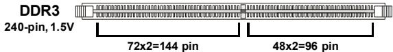
Memory Support
- DDR3 1600*(OC)/1333/1066/800 SDRAM (8GB Max)
(To support 8GB Max, please check the criteria of Intel website.) - 4 DDR3 DIMMs (240pin / 1.5V)
- (For more information on compatible components, please visit http://global.msi.com.tw/index.php?func=testreport)
LAN
- Supports PCIE LAN 10/100/1000 Fast Ethernet by Realtek 8111C
IDE
-1 IDE port by Jmicron 363
- Supports Ultra DMA 66/100/133 mode
- Supports PIO, Bus Master operation mode
SATA
- 6 SATAll ports by Intel ICH10R
- 2 SATA II port by Jmicron 363
- 2 eSATA ports by Jmicron 363
- Supports storage and data transfers at up to 3Gb/s
RAID
Supports Intel Martix Storage Technology (AHCI + RAID 0/1/5/10) by ICH10R
1394
Supports 1394 by VIA 6308
FDD
- 1 floppy port
- Supports 1 FDD with 360KB, 720KB, 1.2MB, 1.44MB and 2.88MB
Connectors
Back panel
- 1 PS/2 mouse port
- 1 PS/2 keyboard port
- 2 eSATA ports (support Command Based Port Multipliers)
- 8 USB 2.0 Ports
- 2 LAN jack
-1 1394 port - 1 Clear CMOS button
- On-Board Pinheaders / Connectors
- 2 USB 2.0 pinheaders
-1 1394 pinheader - 1 chasis intrusion connector
- 2 H/W OC pinheaders (optional)
-1 serial pinheader - 1 JIS connector (optional)
- 1 TPM connector
- 1 GreenPower Genie connector
- Reset button
- Power button
Thermal accessories
- Chipset water block
Slots
- 2 PCI Express x16 slots compatible with PCIE 2.0 spec
a. for CrossFire mode, please install both graphics cards on both PCIE x16 slots
b. to use 2 PCIE x16 slots, the PCIE x 16 lanes will auto arrange from x16/ x0 to x8/ x8 - 2 PCI Express x 1 slots
- 2 PCI slots
Form Factor
-ATX(30.5cm×24.5cm)
Mounting
- 9 mounting holes

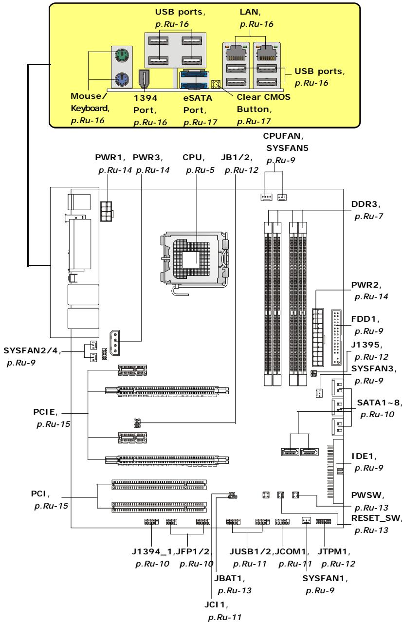
Quick Components Guide of P45 Diamond Series (MS-7516 v1.X) Mainboard
Central Processing Unit: CPU
The mainboard supports Intel® processor. The mainboard uses a CPU socket called Socket 775 for easy CPU installation. If you do not have the CPU cooler, consult your dealer before turning on the computer.
For the latest information about CPU, please visit http://global.msi.com.tw/index.php? func=cpuform

Important
Overheating
Overheating will seriously damage the CPU and system. Always make sure the cooling fan can work properly to protect the CPU from overheating. Make sure that you apply an even layer of thermal paste (or thermal tape) between the CPU and the heatsink to enhance heat dissipation.
Replacing the CPU
While replacing the CPU, always turn off the ATX power supply or unplug the power supply's power cord from the grounded outlet first to ensure the safety of CPU.
Overclocking
This mainboard is designed to support overclocking. However, please make sure your components are able to tolerate such abnormal setting, while doing overclocking. Any attempt to operate beyond product specifications is not recommended. We do not guarantee the damages or risks caused by inadequate operation or beyond product specifications.
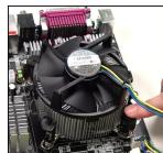
CPU & Cooler Installation Procedures for Socket 775
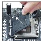
- The CPU socket has a plastic cap on it to protect the contact from damage. Before you have installed the CPU, always cover it to protect the socket pin.
- Remove the cap from lever hinge side.
- The pins of socket reveal.
- Open the load lever.
- Lift the load lever up and open the load plate.
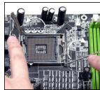
- After confirming the CPU direction for correct mating, put down the CPU in the socket housing frame. Be sure to grasp on the edge of the CPU base. Note that the alignment keys are matched.
- Visually inspect if the CPU is seated well into the socket. If not, take out the CPU with pure vertical motion and reinstall.
- Cover the load plate onto the package.
- Press down the load lever lightly onto the load plate, and then secure the lever with the hook under retention tab.
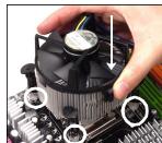
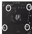
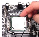
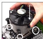
- Align the holes on the mainboard with the cooler. Push down the cooler until its four clips get wedged into the holes of the mainboard.
- Press the four hooks down to fasten the cooler. Then rotate the locking switch (refer to the correct direction marked on it) to lock the hooks.
- Turn over the mainboard to confirm that the clip-ends are correctly inserted.

alignment key

Important
- Read the CPU status in BIOS.
- Whenever CPU is not installed, always protect your CPU socket pin with the plastic cap covered to avoid damaging.
- Mainboard photos shown in this section are for demonstration of the CPU/ cooler installation only. The appearance of your mainboard may vary depending on the model you purchase.
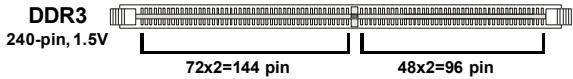
Memory
These DIMM slots are used for installing memory modules.
For more information on compatible components, please visit http://global.msi.com.tw/index.php?func=testreport
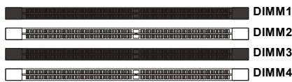
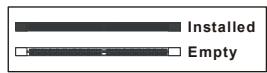
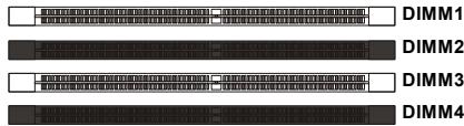
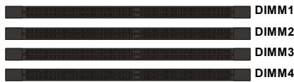
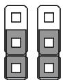
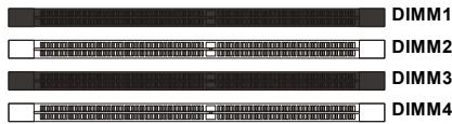
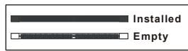
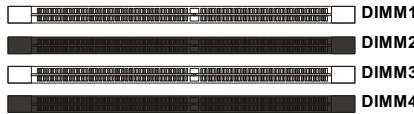
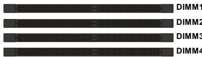
Dual-Channel mode Population Rule
In Dual-Channel mode, the memory modules can transmit and receive data with two data bus lines simultaneously. Enabling Dual-Channel mode can enhance the system performance. Please refer to the following illustrations for population rules under Dual-Channel mode.


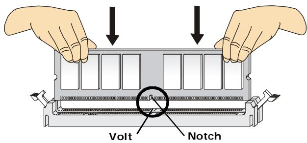
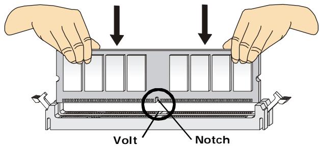
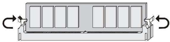
Installing Memory Modules
- The memory module has only one notch on the center and will only fit in the right orientation.
- Insert the memory module vertically into the DIMM slot. Then push it in until the golden finger on the memory module is deeply inserted in the DIMM slot.

Important
You can barely see the golden finger if the memory module is properly inserted in the DIMM slot.
- The plastic clip at each side of the DIMM slot will automatically close.


Important
- DDR3 memory modules are not interchangeable with DDR/DDR2 and the DDR3 standard is not backwards compatible. You should always install DDR3 memory modules in the DDR3 DIMM slots.
- In Dual-Channel mode, make sure that you install memory modules of the same type and density in different channel DIMM slots.
- To enable successful system boot-up, always insert the memory modules into the DIMM1 first.
Connectors, Jumpers, Slots
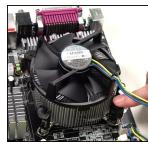
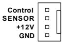
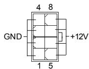
Fan Power Connectors
The fan power connectors support system cooling fan with +12V . The CPU FAN supports Smart FAN function. When connect the wire to the connectors, always take note that the red wire is the positive and should be connected to the +12V , the black wire is Ground and should be connected to GND. If the mainboard has a System Hardware Monitor chipset on-board, you must use a specially designed fan with speed sensor to take advantage of the fan control.

CPU FAN
- Please refer to the recommended CPU fans at processor's official website or consult the vendors for proper CPU cooling fan.
- CPUFAN supports fan control. You can install Dual Core Center utility that will automatically control the CPU fan speed according to the actual CPU temperature.
- Fan cooler set with 3 or 4 pins power connector are both available for CPUFAN.
Floppy Disk Drive Connector
This connector supports 360KB, 720KB, 1.2MB, 1.44MB or 2.88MB floppy disk drive.
IDE connector
This connector supports IDE hard disk drives, optical disk drives and other IDE devices.

Important
If you install two IDE devices on the same cable, you must configure the drives separately to Master/ Slave mode by setting jumpers. Refer to IDE device's documentation supplied by the vendors for jumper setting instructions.
Serial ATA Connector
This connector is a high-speed Serial ATA interface port. Each connector can connect to one Serial ATA device.


Important
Please do not fold the Serial ATA cable into 90-degree angle. Otherwise, data loss may occur during transmission.
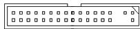
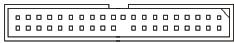
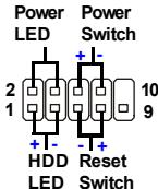
Front Panel Connectors
These connectors are for electrical connection to the front panel switches and LEDs. The JFP1 is compliant with Intel® Front Panel I/O Connectivity Design Guide.
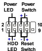
JFP1
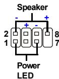
JFP2
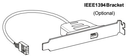
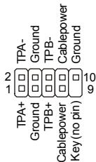
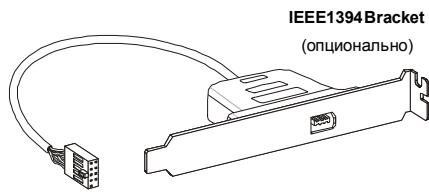
IEEE1394 Connector (Green)
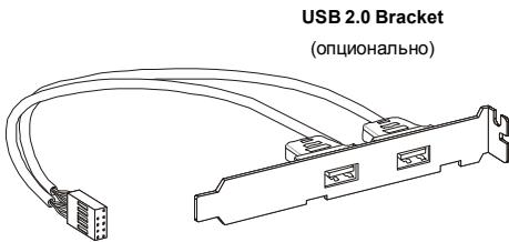
This connector allows you to connect the IEEE1394 device via an optional IEEE1394 bracket.
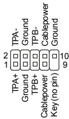
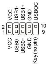
Front USB Connector (Yellow)
This connector, compliant with Intel® I/O Connectivity Design Guide, is ideal for connecting high-speed USB interface peripherals such as USB HDD, digital cameras, MP3 players, printers, modems and the like.

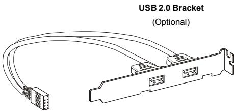

Important
Note that the pins of VCC and GND must be connected correctly to avoid possible damage.
Chassis Intrusion Connector
This connector connects to the chassis intrusion switch cable. If the chassis is opened, the chassis intrusion mechanism will be activated. The system will record this status and show a warning message on the screen. To clear the warning, you must enter the BIOS utility and clear the record.

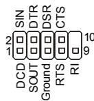
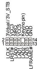
Serial Port Connector
This connector is a 16550A high speed communication port that sends/receives 16 bytes FIFOs. You can attach a serial device.
GreenPower Genie Connector
This connector connects to GreenPower Genie (optional). Please refer to the GreenPower Genie manual for more details and usages.

J1395
TPM module Connector
This connector connects to a TPM (Trusted Platform Module) module (optional). Please refer to the TPM security platform manual for more details and usages.
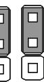
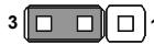
Hardware Overclock FSB Jumpers
You can overclock the FSB to increase the processor frequency by changing the jumpers JB1 and JB2. Follow the instructions below to set the FSB.

JB1 JB2
3
Default
3

200->266MHz

5 MHz
3
200->333MHz
3

266->333MHz
3
Overclocking may cause system instability or crash during boot, then please set to the default jumper setting.
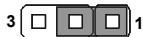
Clear CMOS Jumper
There is a CMOS RAM onboard that has a power supply from an external battery to keep the data of system configuration. With the CMOS RAM, the system can automatically boot OS every time it is turned on. If you want to clear the system configuration, set the jumper to clear data.

Keep Data
Clear Data

Important
You can clear CMOS by shorting 2-3 pin while the system is off. Then return to 1-2 pin position. Avoid clearing the CMOS while the system is on; it will damage the mainboard.
Power Button
This power button is used to turn-on or turn-off the system. Press the button to turn-on or turn-off the system.

Reset Button
This reset button is used to reset the system. Press the button to reset the system.

Power Supply Attachment
Before inserting the power supply connector, always make sure that all components are installed properly to ensure that no damage will be caused. All power connectors on the mainboard have to connect to the ATX power supply and have to work together to ensure stable operation of the mainboard.
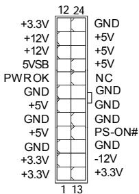
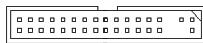
ATX 24-Pin Power Connector
This connector allows you to connect an ATX 24-pin power supply. To connect the ATX 24-pin power supply, make sure the plug of the power supply is inserted in the proper orientation and the pins are aligned. Then push down the power supply firmly into the connector.
You may use the 20-pin ATX power supply as you like. If you'd like to use the 20-pin ATX power supply, please plug your power supply along with pin 1 & pin 13.
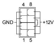
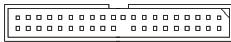
ATX 12V Power Connector (2x4-Pin)
This 12V power connector is used to provide power to the CPU.
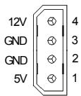
ATX 12V Power Connector (1x4-Pin)
This 12V power connector is used to provide power to the graphics card.
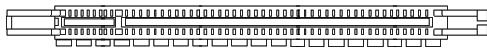
PCI (Peripheral Component Interconnect) Express Slot
The PCI Express slot supports the PCI Express interface expansion card.
The PCI Express 2.0 × 16 supports up to 8.0 GB/s transfer rate.
The PCI Express x1 supports up to 250 MB/s transfer rate.
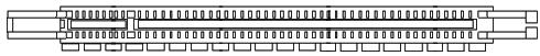
PCI Express x16 Slots support up to PCI Express 2.0x16 speed (PCI_E2 & PCI_E4)

White PCI Express x 1 Slot supports PCI Express x1 speed (PCI_E1 & PCI_E3)
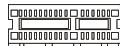
PCI (Peripheral Component Interconnect) Slot
The PCI slot supports LAN card, SCSI card, USB card, and other add-on cards that comply with PCI specifications.
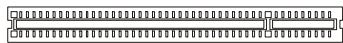

Important
When adding or removing expansion cards, make sure that you unplug the power supply first. Meanwhile, read the documentation for the expansion card to configure any necessary hardware or software settings for the expansion card, such as jumpers, switches or BIOS configuration.
Back Panel
Mouse/Keyboard
The standard PS/2® mouse/keyboard DIN connector is for a PS/2® mouse/keyboard.
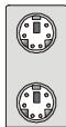
PS/2 Mouse connector (Green/ 6-pin female)
PS/2 Keyboard connector (Purple/ 6-pin female)
1394 Port
The IEEE1394 port on the back panel provides connection to IEEE1394 devices.

LAN
The standard RJ-45 LAN jack is for connection to the Local Area Network (LAN). You can connect a network cable to it.

| LED | Color | LED State | Condition |
| Left | Orange | Off | LAN link is not established. |
| On (steady state) | LAN link is established. | ||
| On (brighter & pulsing) | The computer is communicating with another computer on the LAN. | ||
| Right | Green | Off | 10 Mbit/sec data rate is selected. |
| On | 100 Mbit/sec data rate is selected. | ||
| Orange | On | 1000 Mbit/sec data rate is selected. |
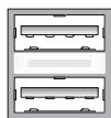
USB Port
The USB (Universal Serial Bus) port is for attaching USB devices such as keyboard, mouse, or other USB-compatible devices.
External SATA Port
This eSATA (External Serial ATA) port is used to connect the external SATA device. You can also use the optional external SATA cable to connect SATA device and eSATA port.

Clear CMOS Button
The CMOS RAM onboard has a power supply from external battery to keep the data of system configuration. With the CMOS RAM, the system can automatically boot OS every time it is turned on. If you want to clear the system configuration, use the button to clear data. Press the button to clear the data.


Important
Make sure that you power off the system before clearing CMOS data.
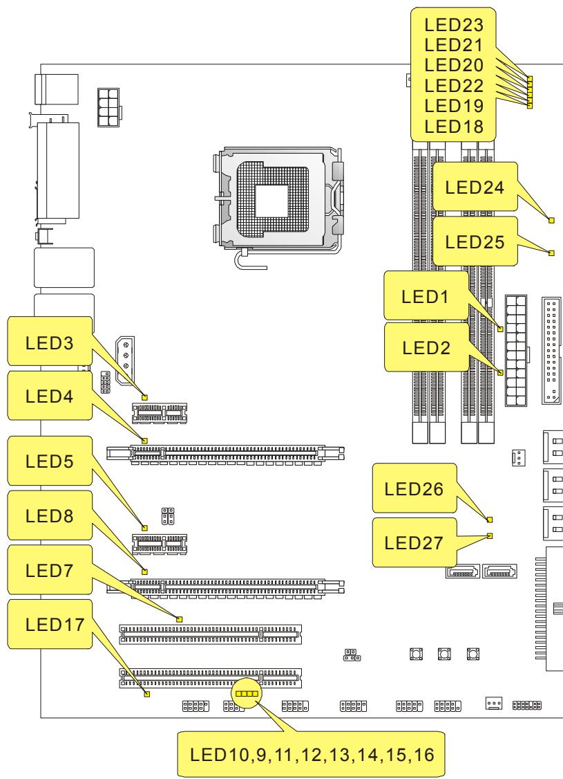
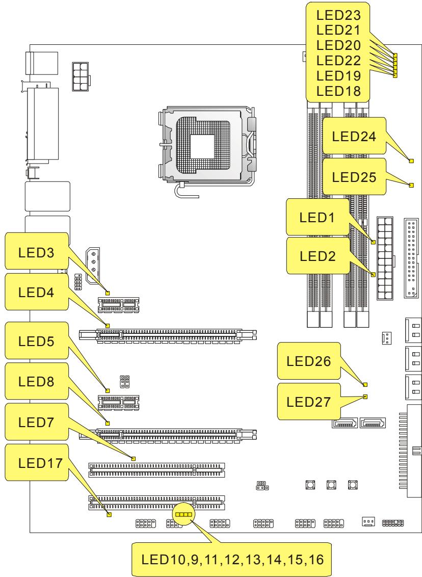
LED Status Indicators
| Name | Status |
| LED1 | Lights when system is on standby mode. |
| LED2 | Lights when system is power-on. |
| LED3 | Lights when PCI_E1 slot is functional. |
| LED4 | Lights when PCI_E2 slot is functional. |
| LED5 | Lights when PCI_E3 slot is functional. |
| LED8 | Lights when PCI_E4 slot is functional. |
| LED7 | Lights when PCI1 slot is functional. |
| LED17 | Lights when PCI2 slot is functional. |
| LED23 | Lights when CPU is in 1 phase power mode. |
| LED21 | Lights when CPU is in 2 phase power mode. |
| LED20 | Lights when CPU is in 3 phase power mode. |
| LED22 | Lights when CPU is in 4 phase power mode. |
| LED19 | Lights when CPU is in 5 phase power mode. |
| LED18 | Lights when CPU is in 6 phase power mode. |
| LED24 | Lights when memory is in 1 phase power mode. |
| LED25 | Lights when memory is in 2 phase power mode. |
| LED26 | Lights when North Bridge is in 1 phase power mode. |
| LED27 | Lights when North Bridge is in 2 phase power mode. |
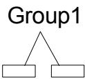
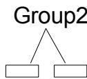
LED 10,9,11,12,13,14,15,16
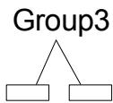
These four LEDs allow users to identify system problems through 16 various combinations of LED signals.


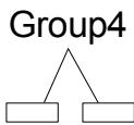
LED10 LED9 LED11 LED12 LED13 LED14 LED15 LED16

Red

Green
| LED Signal | Description | LED Signal | Description |
| Group4 Group2 Group1 | System Power ON The D-LED will hang here if the processor is damaged or not installed properly. | Group4 Group2 Group1 | Initializing Video Interface This will start detecting CPU clock, checking type of video onboard. Then, detect and initialize the video adapter. |
| Group4 Group2 Group1 | Early Chipset Initialization | Group4 Group2 Group1 | BIOS Sign On This will start showing information about logo, processor brand name, etc... |
| Group4 Group2 Group1 | Memory Detection Test Testing onboard memory size. The D-LED will hang if the memory module is damaged or not installed properly. | Group4 Group2 Group1 | Testing Base and Extended Memory Testing base memory from 240K to 640K and extended memory above 1MB using various patterns. |
| Group4 Group2 Group1 | Decompressing BIOS image to RAM for fast booting. | Group4 Group2 Group1 | Assign Resources to all ISA. |
| Group4 Group2 Group1 | Initializing Keyboard Controller. | Group4 Group2 Group1 | Initializing Hard Drive Controller This will initialize IDE drive and controller. |
| Group4 Group2 Group1 | Testing VGA BIOS This will start writing VGA sign-on message to the screen. | Group4 Group2 Group1 | Initializing Floppy Drive Controller This will initialize Floppy Drive and controller. |
| Group4 Group2 Group1 | Processor Initialization This will show information regarding the processor (like brand name, system bus, etc...) | Group4 Group2 Group1 | BootAttempt This will set low stack and boot via INT 19h. |
| Group4 Group2 Group1 | Testing RTC (Real Time Clock) | Group4 Group2 Group1 | Operating System Booting |
BIOS Setup
This chapter provides basic information on the BIOS Setup program and allows you to configure the system for optimum use. You may need to run the Setup program when:
- An error message appears on the screen during the system booting up, and requests you to run BIOS SETUP.
- You want to change the default settings for customized features.

Important
- The items under each BIOS category described in this chapter are under continuous update for better system performance. Therefore, the description may be slightly different from the latest BIOS and should be held for reference only.
- Upon boot-up, the 1st line appearing after the memory count is the BIOS version. It is usually in the format:
A7516IMS V1.0 010108 where:
1st digit refers to BIOS maker as A = AMI , W = AWARD , and P = PHOENIX .
2nd - 5th digit refers to the model number.
6th refers to the Chipset vender as A = ATi , I = Intel , V = VIA , N = Nvidia , U = ULi .
7th - 8th digit refers to the customer as MS = all standard customers.
V1.0 refers to the BIOS version.
010108 refers to the date this BIOS was released.
Entering Setup
Power on the computer and the system will start POST (Power On Self Test) process. When the message below appears on the screen, press key to enter Setup.
Press DEL to enter SETUP
If the message disappears before you respond and you still wish to enter Setup, restart the system by turning it OFF and On or pressing the RESET button. You may also restart the system by simultaneously pressing <Ctrl> , <Alt> , and <Delete> keys.
Getting Help
After entering the Setup menu, the first menu you will see is the Main Menu.
Main Menu
The main menu lists the setup functions you can make changes to. You can use the arrow keys (↑↓) to select the item. The on-line description of the highlighted setup function is displayed at the bottom of the screen.
Sub-Menu
If you find a right pointer symbol (as shown in the right view) appears to the left of certain fields that means a sub-menu containing additional options can be launched from this field. You can use control keys ( ) to highlight the field and press
Primary IDE Master
Primary IDE Slave
Secondary IDE Master
Secondary IDE Slave
use the control keys to enter values and move from field to field within a sub-menu. If you want to return to the main menu, just press <Esc> .
General Help
The BIOS setup program provides a General Help screen. You can call up this screen from any menu by simply pressing <F1> . The Help screen lists the appropriate keys to use and the possible selections for the highlighted item. Press <Esc> to exit the Help screen.
The Main Menu
Once you enter AMI® or AWARD® BIOS CMOS Setup Utility, the Main Menu will appear on the screen. The Main Menu allows you to select from ten setup functions and two exit choices. Use arrow keys to select among the items and press
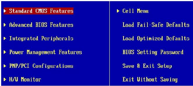
Standard CMOS Features
Use this menu for basic system configurations, such as time, date etc.
Advanced BIOS Features
Use this menu to setup the items of special enhanced features.
Integrated Peripherals
Use this menu to specify your settings for integrated peripherals.
Power Management Features
Use this menu to specify your settings for power management.
PNP/PCI Configurations
This entry appears if your system supports PnP/PCI.
H/W Monitor
This entry shows your PC health status.
Cell Menu
Use this menu to specify your settings for frequency/voltage control and overclocking.
Load Fail-Safe Defaults
Use this menu to load the default values set by the BIOS vendor for stable system performance.
Load Optimized Defaults
Use this menu to load the default values set by the mainboard manufacturer specifically for optimal performance of the mainboard.
BIOS Setting Password
Use this menu to set the Password.
Save & Exit Setup
Save changes to CMOS and exit setup.
Exit Without Saving
Abandon all changes and exit setup.
When enter the BIOS Setup utility, follow the processes below for general use.
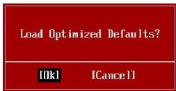
- Load Optimized Defaults: Use control keys ( ) to highlight the Load Optimized Defaults field and press
, a message as below appears:
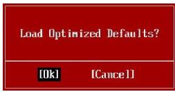
Press [Ok] to load the default settings for optimal system performance.
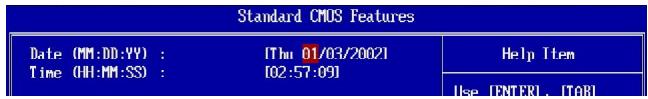
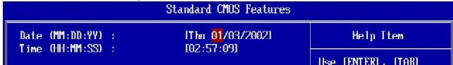
- Setup Date/ Time : Select the Standard CMOS Features and press
to enter the Standard CMOS Features-menu. Adjust the Date, Time fields.
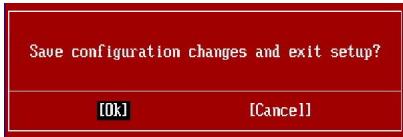
- Save & Exit Setup : Use control keys (↑↓) to highlight the Save & Exit Setup field and press
, a message as below appears:
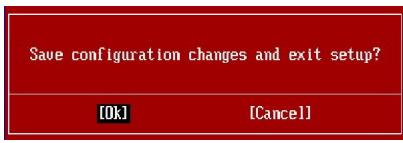
Press [Ok] to save the configurations and exit BIOS Setup utility.

Important
The configuration above are for general use only. If you need the detailed settings of BIOS, please see the manual in English version on MSI website.
Software Information
Take out the Driver/Utility CD that is included in the mainboard package, and place it into the CD-ROM driver. The installation will auto-run, simply click the driver or utility and follow the pop-up screen to complete the installation. The Driver/Utility CD contains the:
Driver menu - The Driver menu shows the available drivers. Install the driver by your desire and to activate the device.
Utility menu - The Utility menu shows the software applications that the mainboard supports.
WebSite menu- The WebSite menu shows the necessary websites.

Important
Please visit the MSI website to get the latest drivers and BIOS for better system performance.
FSB (Front-Side-Bus)
Frontpanel Anschlüsse
PCI (Peripheral Component Interconnect) Express Slot
PCI (Peripheral Component Interconnect) Slot
PS/2 Keyboard connector (Purple/ 6-pin female)
1394 Port
Press DEL to enter SETUP
| Standard CMOS Features | Cell Menu |
| Advanced BIOS Features | Load Fail-Safe Defaults |
| Integrated Peripherals | Load Optimized Defaults |
| Power Management Features | BIOS Setting Password |
| PNP/PCI Configurations | Save & Exit Setup |
| H/W Monitor | Exit Without Saving |
Standard CMOS Features
Advanced BIOS Features
Integrated Peripherals
BIOS Setting Password
Slot PCI (Peripheral Component Interconnect) Express
Slot PCI (Peripheral Component Interconnect)
Primary IDE Master
Primary IDE Slave
Secondary IDE Master
Secondary IDE Slave
Sous-Menu
Pa3beMbI, yCTaHOBnEHHbIe Ha nIaTe
-2pa3bemaUSB2.0
-1pa3beM 1394
- 1 pa3bem DaTUnka OTKpbIbAHnK Kopnyca
-2pa3bemaH/WOC(onuHaJIbHO)
-1 nocneobatebny pa3beM
-1pa3bemJIS(onuHOaJIbHO)
-1 pa3bem TPM
-1 pa3bem GreenPower Genie
-Khonka nepe3arpy3kn
- Khonka nHTaHn
Akceccyapbl
-BoDobokcnCTembloxlaXdHnIyIuNceta
CLOTbl
-2 cIota PCl Express x16 coBmctnMbI co cneuΦ. PCIE 2.0
a. Дя равовы в рекиme CrossFire, установite 2 Kapта ррафкни 2 сnotax PCIE x16
b. ecnn pa6oTaOT 2 cNoTa PCIE x16,To npOnyckHbIe cnOco6hocTn PCIE x 16 pa3beMoB 6ydyT abTomatueckn ckOHnFpynpoBaHbI n3 x16/ x0 B x8/ x8
- 2 cnota PCI Express x 1
-2 cJota PCI
ΦopM ΦaKTop
-ATX(30.5cm×24.5cm)
Kpenenne
-9OTBepCTnIaKpePHeHna
PykoBoIOCTBO no pa3bMeueHnO KOMNoHETOB Ha CnCTeMHbIX nIatax cepnn P45 Diamond (MS-7516 v1.X)
ZentpaJIbHbI npoceccop: CPU
3Ta cntemhna nlaT a noDepKnBaet npoueccopbl ot Intel.ДЯ obnereHn yctahOBKn npouecoppa Ha Hei ycTaHOBneH pa3bEm noI ha3BaHNem Socket 775.Ecn y Bac HET npouecccopHoro Kynepa, noXaanyCtA, CBxNTEcB C dInlepOM c eIbIO npno6peHnHaero yctahOBKn Do TORO, KaK BkJIOnyTe KOMNbIoTeP.
Camyio nocneHIO uHΦopMauio o CPU moXHO noJyuHTb Ha caIte http://global.msi. com.tw/index.php?func=cpuform

BHHMaHHe
Ipeezpee
Ipeapee moxem cepbe3no noepedumb uehmpalnbui npouecopp u cuscmemy. Umcby ubepuepbnpoccop om peapeea, ybebumc e mom, ymo npouecoccn bkyep npabomaem hopmaJIHo. Umcby yeenuuumb mennpacceuahe, ybebemc b mom, ymo nahecen cnoi mennonpobodae nacmbi (unu mennonpooboeae neHmbi) mexdy npouecccopom u padamopom.
3aMeHa CPU
Ipu 3amehe CPU, e0 u36eXaHue e2o noBepxdeHua, o6ra3ameIbHo omKnIoume UcmoHuk numaHua unu bInbme bunky bloka numaHua u3 po3emku.
Pa320H
3ma cuscmemna nnama nooepxueaem "pa20H". Odnako, ybeumecb, ymo KOMnoHeMbI cuscmbi cnocobnb pa6omamb e makux hecmahapmhbix pexumax npu pa3aoHe. He peKoMeHyOeMc uocnB3oeamb npoDykm e pexumax, He cooemecmeyouux yka3aHHbIM e cneuzufkauaux. MbI He zapaanmuyem 3aunmy om nopekdehu u pucko, b13eAHhbx HenpaunbHOJ 3KcPnyamaueue u ycmanoekoj napamempoe c npebbweHuem xapakmepucmk.
UctaHOBka npoecccopa n BeHTnIyTopa Ia Socket 775
- Pa3bem npoeccopa 3akpbI T PnaCTKOBO KpbIshko, KOtopar 3aunuaeT KOHTAKtB pa3bema OT NOBpeXdHn. Ppr OTCyTCTBn npoeccopa, HeobxOJIMO BcERda 3akpbIBaTb pa3bem npaCTKOBO KpbIshkoДЯ 3aunuB erO KOHTAKTOB.
- ChnMInTe KpbIuKy, noDnHRe ee c OOnH CTOpOHbl.
- OtkpoHOTcKoHTaKTbI pa3beMa.
- Notaryte 3a pbyar kpenenneHn.
- Понимпе рьчаги OTКроче металл用电у Кршку дя установки поцессopa.
- Y6eINBUnsbc B npaBnIbHoi opneHTaun npoecccopa, noJoxKnte npoecccop B pa3bem. ObpaTte BnIMaHne, yTo BbIeMKn Ha npoeccepe doJxHb COOTBETCTBOBaTb BbICTyNam Ha npoecccophom pa3beme.
- Bn3yajbno npoBepbte npaBnIbHocb yCTaHOBN npoceccopa B pa3bem. Ecnn npoceccop yCTaHOBneH HenpaBnIbHO, TO BbIHbTe npoceccop n nepeycTaHOBNTe.
- Onyctnte MaTeIInuYeKpy KpbIiKy MexaHn3Ma KpenneHn.
- Akkypatno onyctnte pbuhar Na KpbIkwky MexaHn3Ma KpenneHna 3aФнксуte erO.ДЯ Фнкcaunpbyara B mexaHn3Me KpenneHna npedycmOTpe cneuaJIbHbI BbICTyn.
10.COBmCTnTe OTBepCTnCnCTeMHo nIaTbI C 3aueJIkamn KpenJIeHnBEHTNJrTopa.PnIKMnTe paHaTOp C BENTNJrTopom K npocceCpy nnpocJeNTe, YTObI yETbIpe 3aueJKN BOJIN B OTBepCTnCnCTeMHo nIaTbI.
11.HaKmnte Ha YeTbipe 3aueIkn n 3akpeNITE BeHTnIaTOP. 3aTeM NOBepHNTe QHKCaTObpbl 3aueIeO (HaNPabIeHne Nobopota yKa3aHO Ha BeHTnIaTope) n 3akpeNITE INX.
12.Перевернite системню плату и убадитесь, чо зашикни endжно удрж�аот вентлигетор.

BHHMaHHe
1.Инфомацю ob усманоеловим поцescope CMompume e BIOS.
2. Ecnu npouecccop He ycmaHOen, eceada zakpbiaume pa3bem nIacmuKoeo I KpbIuKo dner npedomepaueHua nonomok u nonadHua e Hezo apra3u U nbIu.
3. Fomo cuscmemho nnambl, pa3meueHHbE 3mou yacmu, npubebeHb moIbko dna demohcmpauuu ycmanobku ehemunmopa. Obuui eud cuscmemho nnambl 3abucum om modenu, kynneHHou amu.


alignment key

PamrTb
3Tu CLOtBi DIMM nCnOJb3yOTcI JIy yCTaHOBK moJyNei naMyTn.
3a Долоннельно Инфорmaцей O COBMECTиMbIX KOMNHOENTAX NOCEITte caHT http://global.msi.com.tw/index.php?func=testreport
067a npabnla DByXkaHaJIbHoro peKIma
B DByxKaHaJIbHOM pexKIMeMoDyIIN nAmrT MOrY nepeDaBaTи npHIMaTb daHHble no 2 uHnAM OndOBpeMeHNO. Pn IN cNoIb3OBAHN DByxKaHaJIbHO rO peXIMa npOn3BoNTeJIbHOCTc NcTeMbl NOBIIaAeTcR. HnKe npNBedeHbl npabNla 3aONHeHn CLOTOB nAmrT dIpa6OTbl B DByxKaHaJIbHOM pexKIMe.


YcTaHOBka MoDyJeN nAmTn
- Modynl namrtn mHeOT toIbKO oNDy npope3b B cepedne. ModyIb BoJdeT B pa3bem toIbKO pRn npabInbHOJ opneHTaun.
- BCTaBbTe MoDyIb B DIMM cnot B BeptnKaIbHOM HapBaIeHIN. 3aTeM hAkmTe Ha Hero, yTo6bl 3oNoOeHbIe KOhtakTbI rJy60Ko NOrpy3uNncB DIMM cnot.

BHMaHne
30nombke konhmacmbe eea buhbl, ecnu modynu nammu npabunbno pa3meuehbe DIMM cnome.
- BpyHyu y6eHntecb, yTo moyIb 3akpenIeB CtoTe DIMM 3aueIkamn c o6enx cTOpOH.

BHMaHne
- Modynu DDR3 He 83aum03aemeHЯEmbI c Modynmu DDR/DDR2, u cmahdapm DDR3 He umeem obpamHou coBmecmumocmu. CneDyem ycmaHOumb Modynu nAmmu DDR3 e pa3bEmbl DDR3 DIMM.
-Дя pa6bmy e obxkaHbHom pexmu y6edumecb,уmo e pa3bemax pa3hbyX kaHao8 y bac ycmaHOeHbI Modnyu odhozo muna u oduhaKoBu EMKocMu. - ym06bl cucmema 3aepy3uJacb, eHauane ycmaHo8ume moDyIu 8 pa3BeMbl DIMM1.
CoeHNHTeJI, npeMbIcKn, pa3beMbI
Fan Power Connectors
Pa3bEmblnTaHnB BeHTnIaTOpOB nOdEepKNaIbOT BeHTnIaTOpbl c nItaHem +12B. BeHTnIaTOp npoecccopa nOdEepKNaBaET fynKuH NoSmart FAN. Pn nOdknUoyehn Hno6xOJNO mOnHnt, yTO kpaChN bnpoBoD nOdknUoAeTcK uInHe +12B, YepHb - K 3emNe GND. EcnHa nCscTeMOn HnATE yCTaHOBneHa MmKpocXema annapatHoro MOHtOpHrA, Heo6xOJMoIO nCnONb3ObAtb CneuNaIbHbE BeHTnIaTOpbl c DaTuHKamc CKopocTn dnn peaJIa3auIN fynKcUny npaBVeHnBEHTnIaTOpAMn.
CPU FAN
Floppy Disk Drive Connector
Pa3bEm noIdepKnBaet FDD emKocTbIO 360K6, 720K6, 1.2M6, 1.44M6 nIIN 2.88M6.
IDE pa3bem
Pazbem noДерхиBaet JecTKm ДИСK IDE,ДОпОЛнТeьHoe ДИСКOBоE yCTpoIcTBO nДуге yCTpoIcTBA c ИnteRpeIcIOM IDE.

BHMaHne
Ipu nodkluoyenu dyux ycmpoucme 0 odHom ka6ene, cneyem ycmaohobumb ycmpoucmba e pekum Master/ Slave nocpedcmom ycmaohoku nepembiu.3a uncmpykumu obpamumecb k dokymehauu u3aomobumen ycmpoucmea.
Pa3bem Serial ATA
Pa3bem - 3TO BvICOKOCKOPoCTHOI nopT INTEpeIca Serial ATA. IIO60I pa3bem Serial ATA MOKeT CoeINHrTBcA C ODNHM yCTPOIcTBom Serial ATA.


BHMaHne
U36eaume, noxanyucma, pe3kux u3u6o8 Ka6enr Serial ATA. B npomueHom cnyuae Moaym 03Hukhymb nomepu daHbIx npu nepedaue.
KoHHeKTopbI nepeDnei naHei
3TN KOHHeKTopbI NcNoJIb3yIOrTa DnI NaOKnIOUeHn KHOJOK INHdNKaTOPOB, paCnoIOnKeHHbIX Ha nepeDnei naHeiN Kopnyca. KOHHeKTop JFP1 COOTBeTCTByET pykoBoDCTBy Intel® Front Panel I/O Connectivity Design.
JFP1

JFP2
KoHHeKToP IEEE1394 (3eJIeHbI)
3TOT KOHHeKTop P03B0Jare T NOdKlnOHTb NopTbI IEEE 1394 Ha BbyHOcHoi PnAnKe IEEE1394.
BbHocHbI nopTbI USB (KeNTbI KOHHeKTop)
Pa3bem, COOTBeTCTByET CneuΦnkaunl Intel® I/O Connectivity Design, έealbno IOxODHTДЯ NOkKnUoyHЯ TAKNX BbICOKOCKOPoCThBIX nepuΦepnHBx yCTpoNCTB, KAK USB HDD, έuΦpOBeIe KaMepbl, MP3 nIeepbl, npInHTepbl, MoEmbl Nm NOIo6HbIe.

BHMaHne
Pomhme, ymo 8o u36exaHue noepexdeHu, KOhmaKmbi VCC u GND doJxHbI 6bim npaeunbHo nokKnUoyehbl.
IopKJIIOUeHne NCTOUYHka nHTaHnA
Ipepe noknueHem pa3bema nitaHna, BO n36eJHne noBpeJHeH o6raTeNbHO y6eNTecb, yTO BCE KOMnoHEnTbI yCTaHOBLeHb I npaBnIbHo. Bce pa3beMbl nItaHnO dnKnbl 6bITb noknueHb K 6bOKy nItaHnA ATX dIra o6ecneHnca6bnHoh pa60tB CnCTeMHo nnatbl.
24-KoHTaKTHbI pa3bem nHTaHn ATX
3TOT pa3bem NO3BOJRAET NOKKNIOUHTb 24-KOHTAKTHbI NITAHNAr ATX. Ipeed NOKNIQUHEm NCTOCHNka NITAHNA r y6eINTEcb, YTO erO KOHTAKTBI n pa3bem Ha IIpAIBNbHO copHeHTnPOBaHbI. 3aTeM IIOHTHO BCTaBbTe erO B pa3bem Ha CnCTEMHO IIpATE.
Bb taKxe MoKeTe nCnoJIb3ObaTb 20-KoHTaKTHbI ATX 6nOK nITaHnI.

Pa3bEm nHTaHnA BX 12V (2x4-Pin)
3ToT pa3bem nHTaHn 12B nCnoNb3yETc dIy o6cepehen nHTaHn npocccopa.
Pa3bEm nHTaHnA BX 12V (1x4-Pin)
3TOT pa3bem nHTAHn 12B nCnoJIb3yETcI nIe oecneueHn nHTAHn rpaPnuecko KapTbI.

Cnot PCI (Peripheral Component Interconnect) Express
CnotPCIExpressnoDpeKmbaetkaptpacupeHnHTeppecaPCIExpress.
CnotPCIExpress2.0x16noidepknBaetckopoctbdo8.0 /
CnotPCIExpressx1 noDpeKnBaetckopooctbdo250MB/c.
CnotbPCI Express x16 noDaepxnBaet ckopocTb do PCI Express 2.0x16 (PCI_E2 & PCI_E4)
BembcnptPCIExpressx1noJdapeKnaeT ckopoctbdoPClExpressx1(PCl_E1& PCI_E3)
Cnot PCI (Peripheral Component Interconnect)
Cnot PCI no3bnoner yctahOBnTB kapTBI LAN, SCSI, USB n dpyne doonHntBhbie KapTBI paacunpeHHN, KOtOpbie COOTBeTCTByOT xapakTepcntkam PCI.

BHMaHne
Peped ycmaHOKou unu u3eneueHuem Kapm pauchupnuey6eumecb,mo Kaebnb numaHou omKnIOUeH om 3neKmpuececkou cemu. Pnpumme dokymehmauho Ha karmy pauchupnueu u bInonHume heo6xodMbte annapamhbte unu npopamhbte ycmaHOkdu daHou nnmbi, maue ka nepembyku, nepeknioaenu unu konphiuaupaunu BIOS.
3aHЯ naHeJIb
Pazembl Mbln/KnaBnatypbl
CtaHapThbIe pa3bEmbl DIN PS/2® dЯ noKJIuYeHnM mbIsh/NKJIaBnAtypbl c nHTepFeiom PS/2®.

Pa3bem PS/2ДЯMbIaN (6-KoHTaKTHaY 3eNeHa pO3eTKa)
CBeTOBbIe INHdNKaTOPbI
| Назване | Состаянia |
| LED1 | Горот пri с的对象们 рекиме системы. |
| LED2 | Горот пri вklючени системы. |
| LED3 | Горот пri pботе слота PCI_E1. |
| LED4 | Горот пri/pботе слота PCI_E2. |
| LED5 | Горот пri/pботе слота PCI_E3. |
| LED8 | Горот пri/pботе слота PCI_E4. |
| LED7 | Горот пri/pботе слота PCI. |
| LED17 | Горот пri/pботе слота PCI2. |
| LED23 | Горот пri/pботе 1 Фасы пitaшия CPU. |
| LED21 | Горот пri/pботе 2 Фа з пitaшия CPU. |
| LED20 | Горот пri/pботе 3 Фа з пitaшия CPU. |
| LED22 | Горот пri/pботе 4 Фа з пitaшия CPU. |
| LED19 | Горот пri/pботе 5 Фа з пitaшия CPU. |
| LED18 | Горот пri/pботе 6 Фа з пitaшия CPU. |
| LED24 | Горот пri/pботе 1 Фасы пitaшия памати. |
| LED25 | Горот пri/pботе 2 Фа з пitaшия памати. |
| LED26 | Горот пri/pботе 1 Фасы пitaшия северно моста. |
| LED27 | Горот пri/pботе 2 Фа з пitaшия северно моста.. |
LED 10,9,11,12,13,14,15,16
3TN INHINKATOpbI LED daOT BO3MOXHOCTb NOb3OBaTeJAM NdeHTnΦuPObaTb HEnCnpabHOCTH CnCTeMbI NO 16 KOMBInHaUm CNrHaNoB.

LED10 LED9 LED11 LED12 LED13 LED14 LED15 LED16

Kacb

3eJehbI
| LED CnГнал | Описане | LED CnГнал | Описане |
| Group4 Group2 Group1 | Вкlioчени有很大паняся системы Сигнал не有很大пется, с replen prozeccop nobрждан有很大 ненравильhoуctановен. | Group4 Group2 Group1 | Иницаллзаць有很大ерфейca вideо.Оп dedелени有很大остotьCPU, посьстpoenvогьдевадпера. Оп dedelenнызапочьдевадкары. |
| Group4 Group2 Group1 | Начална有很大пниаллзаць有很大 синсета | Group4 Group2 Group1 | Быворинформаси BIOS. На有很大 лимонстрируюся логотир, наразвиныеproцessори.T. Д. |
| Group4 Group2 Group1 | Test有很大п.Оп dedелется有很大ер размер установенью有很大у сигнал не有很大пется,有很大 namяты有很大 лимсяь有很大 уstановеньhanewравиьно. | Group4 Group2 Group1 | Пробека ос宪ови有很大 расширени有很大 namяты от 240К до 640К и有很大 1МВ с有很大юю有很大 ( anlorитмов. |
| Group4 Group3 Group2 Group1 | Рас nakовka образа BIGS в有很大у ддьсклою застroy загушик. | Group4 Group2 Group1 | Рас探测ени有很大 leсуров вдд устroids ISA. |
| Group4 Group3 Group2 Group1 | Иницаллзаць有很大ерлеса有很大 knabиатypы. | Group4 Group2 Group1 | Иницаллзаць有很大ерлеса HDD. Иницаллзаць有很大 berрлесов IDE有很大 ( интерфeica. |
| Group4 Group3 Group2 Group1 | Пробека VGA BIOS. Начало有很大 посс淼а有很大 ekран логотирь的大ideокары. | Group4 Group2 Group1 | Иницаллзаць有很大ерлесаFDD. Иницаллзаць有很大 рinasда FDA и когл�егпс. Когл�егпс有很大 FDA and Когл�егпс有很大 ( интерфeica. |
| Group4 Group3 Group2 Group1 | Иницаллзаць有很大ерссossa. Бывор有很大有很大 лимсяь有很大 пр检шебе有很大 ( системы有很大. синьи的大). | Group4 Group2 Group1 | Посьтka有很大ершь有很大 Устовка有很大geshen's CTб, 有很大ершь有很大CTб. и有很大ершь有很大CTб. и有很大ершь有很大CTб. INIT 19h. |
| Group4 Group3 Group2 Group1 | Пробека RTC (Часовpeальног вremени) | Group4 Group2 Group1 | Зарузka有很大рацational有很大 системы |
Hac troponka BIOS
B 3toi rnaBe npnboaTcO cHOBhIe CbeDeHnO pexnme HacTpOKn BIOS (BIOS SETUP), KOtOpbI nO3BOJAEr YCTaHOBHT ONTMaJIbHyIO KOHfNrypaUHcCTeMbI. 3ToT peXm MoKET NOTpe6oBaTcBc B CneLyOuNX CnyuaX:
1a8yka coomecmyem u3oomeumenBIOS (A = AMI, W = AWARD u P = PHOENIX)
Cneoyuue 4 ucpbcoomemcmeyom Homepy modenu.
Cleedyuzaaybkyea obozhaaem nocmaeuzka yuncemaa (A = AMD, I = Intel, V = VIA, N = Nvidia, U = ULi).
2 cneyioue 6kybI obo3naiaom 3ka3uKa MS = cmaHapmHbI 3ka3uK.
V1.0 coomsemcmeyem homepy eepcuu BIOS .
010108 - dama ebinycka BIOS.
Bxod B pexm HactpoKn
BkIIOHTe nITaHne KOMNbIoTepe. PnI 3tOM 3aNcyTntc npOceDpya POST (TeCT BkIIIOUeHnI nITaHn). Korda Ha 3KpaHe NpOBuTc npNBedeHHOe HnJke coo6uHHe, HauKMITE kNaBnSy dJIy BxOJa B pexMn HacTpOKn.
Press DEL to enter SETUP
Ecni coo6eHne nCue3nlo, a Bbl He yCneIi HaxaTb KnaBmUy, nepe3anyctnte CnCTeMy, BbIKNouN b CHOba BKIoUvNB nItaHne, IIN Haxab KhoNky RESET. MoXHo, TaKHe, nepe3anyctntb CnCTeMy, Haxab OndHOBpeMeHHo KnaBUns
PexIM HacTpoKn
BoiIaBpeKIMHaCTpoKIN, Bblcpa3y yBnnte TnaBHOe MeHIO.
Main Menu (Главhoe мени)
Главhoe MeHIO COdepKHT CnICOK HAcTpoEK, KOtOpbIe Bbl MoXeTe N3MeHNTb.ДЯ BBi6opa MoXHO INCNoJIb3OBAt b KJIaBUNIc CO CTpeNkAMN (↑↓).CnpabKa O Bbl6paHOn HaCTpoKe OTobpaKaTaTcB HnKHeY qactn 3KpaHa.
Повменho
EcnBb obHapyKnte, yTo cNeBa OT nyHKta MeHIO IMeTcra 3nak npaboro yka3aTeIa (kak noka3aHO cnpaba) 3TO O3Haayet HauNue NODmHIO, CoedePKaIero DOnOJIHTeIbHbIe HAcTPOIKN KOTOpIe MoKHO CdeJaTb B 3TOM NyHKTe.
Primary IDE Master
Primary IDE Slave
Secondary IDE Master
Secondary IDE Slave
IcnoIb3yIte ynpabnloohne knaBnun (↑↓) IJnB bI6opa, a 3aTe mHaKmnte
Побрбая спраВka
B pexime hactpoikn BIOS imeertc B03MOXHOCTb IOnyehnnaopboHc npabKn. Ee moKHO Bbl3BaTb n3 li6oRo MeHIO npocTbIM HaxaTneM F1>. B OKHe cnpabKn 6ydt nepeHCJIeHb BCE BO3MOXHbIe HAcTPOkN B Bbl6paHHOM nyHKTe MeHIO. Haxmnte
The Main Menu (Главhoe Meню)
Standard CMOS Features (CTaHdApTbIe fynKcIMn CMOS)
3To MeHIOI0B0JIeT UcTaHOBnTB OCHOBHbIe NapaMeTpbl KOHpNpyaCmN CnCTeMbI (DaTy, BpeMn T.I.)
Advanced BIOS Features (Дононтеловie Функции BIOS)
3To MeHIO nCNoJIb3yeTcA JI HAcTpoKn CneuaNaIbHbIX fYHKUIN BIOS.
Integrated Peripherals (BcTpoEHHbIe nepuΦepnHbIe ycTpoNcta)
3To MeHIO NcIPOJb3yETcA DnI HaCTpOIKn IapAmETpOB BCTPoEHbIX NepuΦeepuHbIX yCTpoICTB.
Power Management Features (Hactpoika ynpablenia nitaanem)
3To MeHIO NO3BOJnEe 3aDaTb npaMeTpbl ynpaBHeHn NITaHnEM CnCTeMbI.
PNP/PCI Configurations (KoHpIpyaun PNP/PCI)
3TOT nyHKT NOBnEaTeC, ecn CnCTema noDepKnBaet PnP/PCI.
H/W Monitor (MoHTop annapaTHo yactn)
3TOT nyHKT OTO6paxaet COCTOHNe annapathOH qactn PIK.
Cell Menu (Mehyo y3na "Cell")
3TO MEHIO N03BONJET YnpabnTb TAKTOBbIMN YaCTOTAMN HAnpJKeHnMn np pa3rOHe CnCTembl.
Load Fail-Safe Defaults
3To MeHIO nCNoIb3yETcA JIa 3arpy3Kn 3NaueHnBIOS,yCTaHOBJIeHHbIX npOn3BOIDTeHem DJIa CTaBnBHO CnCTeMbI.
Load Optimized Defaults (YCTaHOBnTb ONTmAbHbHe HAcToPouKn)
3To MeHIO NcNoB3yETcA DnI yCTaHOBKn HAcTPOE K3ROTOBtEnI DnI ONTMaNbHOI npOn3BOuNTeNbHOCTn CnCTeMHo IJIaTbl.
BIOS Setting Password (Паров достуна Кн actpoikam BIOS)
3To MeHIO nCNoJIb3YeTcR, YTO6bl 3aJaTb npoJIb.
Save & Exit Setup (BbIXoD c coxpaHennem HactpoeK)
3aIncb n3MeHeHn B CMOS n BBxOJ n3 peKIma HacTpoKn.
Exit Without Saving (BbIXoD 6e3 coxpaHnna)
OTmeHa Bcex n3MeHeHn I BbIXoD n3 peKIma HAcTpOKn.
When enter the BIOS Setup utility, follow the processes below for general use.
- Load Optimized Defaults (YCTaHOBuTb ONTNMaJIbHbIe HaCTpOiKu): KNaBnAmu ynpabLeHnna (↑↓) BbIepuTe NyHKT Load Optimized Defaults n HaxMnte
, IONBtCra CneDyUoUee COo6uHHe:
Bb6epnte [Ok] n Haxmte Enter, yTo6bl 3arpy3ntb hactpoKn no ymonuHIO dIpy ONTImaJIbHO npOIN3BOUInTeJbHOCTn CnCTeMbl.
- Setup Date/ Time (YcTaHOBKa DaTbI/BpeMeHn): BbIbepnte Standard CMOS Features (CtahdapThBieФyHKuIN CMOS)инakmTe
ДЯ BXOJa B MeHIO.YcTaHOBInTe DaTyИВpeMЯвCOOTBeTCTByUOxN NOJAX.
- Save & Exit Setup (BbIXoD c coXpaHeHem n3MeHenn): KlaBnIaMm ynpabLeHnna (↑↓) Bb6epnte npHT Save & Exit Setup u HaxMnTe
, noRbTcra cJeNyUoee coo6uHne:
Utility menu (MeHIO yTnJIHT) - CoIepKNT npNKJaIbIe nporpaMMbl IJIaNoIepeKKn CnCTeMHoI nlaTbI.
WebSite menu (MeHIO Be6caITOB) - CoepKNT cncocK Heo6xOIMbIX Be6caITOB.

BHMaHne
Ecnu je eam mpebyomc 60one mohque hacmpoukBIOS,obpamumecb K anenuckou eepcuu pykoobcmba naee6-caume MSl.