
G52-73951X7 - Laptop MSI - Free user manual and instructions
Find the device manual for free G52-73951X7 MSI in PDF.

| Product Type | MSI Laptop Motherboard |
| Model | G52-73951X7 (MS-7395 v1.X) |
| Form Factor | ATX (30.5 cm x 24.5 cm) |
| Supported Processors | Intel Core 2 Quad, Core 2 Duo, Pentium, Celeron (socket LGA775) |
| FSB | 1333 / 1066 / 800 MHz |
| Chipset | Intel P35 (North Bridge) + ICH9 (South Bridge) |
| Memory | DDR2 1066/800/667 SDRAM, 4 DIMM slots, max 8 GB, 1.8 V |
| Audio | Realtek ALC888, 8 channels, Azalia 1.0 and Vista Premium compatible |
| LAN | Realtek 8111B Gigabit Ethernet (10/100/1000) |
| IDE Storage | 1 IDE port (Ultra DMA 66/100/133) via JMicron JMB363 |
| SATA Storage | 4 SATA II ports (ICH9) + 2 SATA II ports (JMicron JMB363), up to 300 MB/s |
| RAID | RAID 0, 1, JBOD (on SATA5 and SATA6 ports via JMicron) |
| Rear Connectors | 1 PS/2 mouse, 1 PS/2 keyboard, 1 serial port (COM1), 1 parallel port (SPP/EPP/ECP), 4 USB 2.0, 1 LAN, 6 flexible audio jacks |
| Internal Connectors | 4 USB 2.0, 1 CD-In, 1 front audio, 1 TPM (optional), 1 SPDIF-Out, 1 serial, 1 chassis intrusion, 1 infrared |
| Expansion Slots | 1 PCI Express x16, 1 PCI Express x1, 4 PCI (3.3 V/5 V) |
| Power | ATX 20-pin connector + ATX 12V (2x2, 2x4 or 1x4 pin) |
| Special Features | Overclocking via jumpers (JB1/JB2), D-Bracket 2 diagnostic, CMOS clear button |
| Maintenance and Cleaning | Regular cleaning with compressed air, avoid moisture, use thermal paste between CPU and heatsink |
| Safety | Disconnect power before any intervention, comply with WEEE directive, protection against overloads and short circuits |
| Spare Parts and Repairability | CPU, memory, heatsink, CMOS battery replaceable; standard screws and brackets; documentation available online |
| General Information | Manual provided in PDF format (108 pages), available languages: FR, DE, EN, RU |
Frequently Asked Questions - G52-73951X7 MSI
User questions about G52-73951X7 MSI
0 question about this device. Answer the ones you know or ask your own.
Ask a new question about this device
Download the instructions for your Laptop in PDF format for free! Find your manual G52-73951X7 - MSI and take your electronic device back in hand. On this page are published all the documents necessary for the use of your device. G52-73951X7 by MSI.
USER MANUAL G52-73951X7 MSI
The material in this document is the intellectual property of MICRO-STAR INTERNATIONAL. We take every care in the preparation of this document, but no guarantee is given as to the correctness of its contents. Our products are under continual improvement and we reserve the right to make changes without notice.
Trademarks
All trademarks are the properties of their respective owners.
NVIDIA, the NVIDIA logo, DualNet, and nForce are registered trademarks or trademarks of NVIDIA Corporation in the United States and/or other countries.
AMD, Athlon™, Athlon™ XP, Thoroughbred™, and Duron™ are registered trademarks of AMD Corporation.
Intel® and Pentium® are registered trademarks of Intel Corporation.
PS/2 and OS®/2 are registered trademarks of International Business Machines Corporation.
Windows® 95/98/2000/NT/XP are registered trademarks of Microsoft Corporation.
Netware® is a registered trademark of Novell, Inc.
Award® is a registered trademark of Phoenix Technologies Ltd.
AMI^® is a registered trademark of American Megatrends Inc.
Revision History
Revision
V1.1
Revision History
First release
Date
October 2007
Technical Support
If a problem arises with your system and no solution can be obtained from the user's manual, please contact your place of purchase or local distributor. Alternatively, please try the following help resources for further guidance.
Visit the MSI website for FAQ, technical guide, BIOS updates, driver updates, and other information: http://global.msi.com.tw/index.php? func=faqIndex
Contact our technical staff at: http://support.msi.com.tw/
- Always read the safety instructions carefully.
- Keep this User's Manual for future reference.
- Keep this equipment away from humidity.
- Lay this equipment on a reliable flat surface before setting it up.
- The openings on the enclosure are for air convection hence protects the equipment from overheating. DO NOT COVER THE OPENINGS.
- Make sure the voltage of the power source and adjust properly 110/220V before connecting the equipment to the power inlet.
- Place the power cord such a way that people can not step on it. Do not place anything over the power cord.
- Always Unplug the Power Cord before inserting any add-on card or module.
- All cautions and warnings on the equipment should be noted.
- Never pour any liquid into the opening that could damage or cause electrical shock.
- If any of the following situations arises, get the equipment checked by a service personnel:
The power cord or plug is damaged.
† Liquid has penetrated into the equipment.
† The equipment has been exposed to moisture.
† The equipment has not work well or you can not get it work according to User's Manual.
† The equipment has dropped and damaged.
† The equipment has obvious sign of breakage.
- DONOT LEAVE THIS EQUIPMENT INAN ENVIRONMENT UNCONDITIONED, STORAGE TEMPERATURE ABOVE 60^ (140°F), IT MAY DAMAGE THE EQUIPMENT.

CAUTION: Danger of explosion if battery is incorrectly replaced. Replace only with the same or equivalent type recommended by the manufacturer.

警告使用者:
For better environmental protection, waste batteries should be collected separately for recycling or special disposal.
This equipment has been tested and found to comply with the limits for a Class B digital device, pursuant to Part


N1996
15 of the FCC Rules. These limits are designed to provide reasonable protection against harmful interference in a residential installation. This equipment generates, uses and can radiate radio frequency energy and, if not installed and used in accordance with the instructions, may cause harmful interference to radio communications. However, there is no guarantee that interference will not occur in a particular installation. If this equipment does cause harmful interference to radio or television reception, which can be determined by turning the equipment off and on, the user is encouraged to try to correct the interference by one or more of the measures listed below.
† Reorient or relocate the receiving antenna.
† Increase the separation between the equipment and receiver.
Connect the equipment into an outlet on a circuit different from that to which the receiver is connected.
Consult the dealer or an experienced radio/television technician for help.
Notice 1
The changes or modifications not expressly approved by the party responsible for compliance could void the user's authority to operate the equipment.
Notice 2
Shielded interface cables and A.C. power cord, if any, must be used in order to comply with the emission limits.
VOIR LANOTICE D'INSTALLATIONAVANT DE RACCORDERAU RESEAU.

This device complies with Part 15 of the FCC Rules. Operation is subject to the following two conditions:
(1) this device may not cause harmful interference, and
(2) this device must accept any interference received, including interference that may cause undesired operation.

ENGLISH
To protect the global environment and as an environmentalist, MSI must remind you that...
Under the European Union ("EU") Directive on Waste Electrical and Electronic Equipment, Directive 2002/96/EC, which takes effect on August 13, 2005, products of "electrical and electronic equipment" cannot be discarded as municipal waste anymore and manufacturers of covered electronic equipment will be obligated to take back such products at the end of their useful life. MSI will comply with the product take back requirements at the end of life of MSI-branded products that are sold into the EU. You can return these products to local collection points.
DEUTsCH
Safety Instructions . 3
FCC-B Radio Frequency Interference Statement .iv
WEEE (Waste Electrical and Electronic Equipment) Statement.
English En-1
Specifications En-2
Central Processing Unit: CPU En-5
Memory En-7
Connectors, Jumpers, Slots En-9
Back Panel. En-18
BIOS Setup. En-21
Software Information. En-25
Deutsch. De-1
Central Processing Unit: CPU Fr-5
Memoire Fr-7
| Processor Support |
| - Intel® Core 2 Quad/Core 2 Duo/Pentium/Celeron processors in the LGA775 package - Support Intel® Yorkfield, Wolfdale (For the latest information about CPU, please visit http://global.msi.com.tw/index.php?func=cpuform) |
| Supported FSB |
| - 1333/ 1066/ 800 MHz |
| Chipset |
| - North Bridge: Intel® P35 chipset - South Bridge: Intel® ICH9 Base chipset |
| Memory Support |
| - DDR2 1066/800/667 SDRAM (8GB Max) - 4 DDR2 DIMMs (240pin / 1.8V) (For more information on compatible components, please visit http://global.msi.com.tw/index.php?func=testreport) |
| LAN |
| - Supports PCIE LAN 10/100/1000 Fast Ethernet by Realtek 8111B |
| Audio |
| - Chip integrated by Realtek® ALC888 - Flexible 8-channel audio with jack sensing - Compliant with Azalia 1.0 Spec - Meet Microsoft Vista Premium spec |
| IDE |
| - 1 IDE port by JMicron JMB363 - Supports Ultra DMA 66/100/133 mode - Supports PIO, Bus Master operation mode |
| SATA |
| - 4 SATA II ports by ICH9. - 2 SATAII ports by JMicron JMB363. - Supports storage and data transfers at up to 300 MB/s |
| RAID |
| - Supports RAID 0, 1 and JBOD by JMicron JMB363. (SATA5, SATA6) |
| FDD |
| - 1 floppy port - Supports 1 FDD with 360KB, 720KB, 1.2MB, 1.44MB and 2.88MB |
Connectors
Back panel
- 1 PS/2 mouse port
- 1 PS/2 keyboard port
- 1 serial port (COM1)
- 1 parallel port supporting SPP/EPP/ECP mode
- 4 USB 2.0 Ports
- 1 LAN jack (10/100/1000)
- 6 flexible audio jacks
- On-Board Pinheaders / Connectors
- 4 USB 2.0 pinheaders
- 1 CD-In connector
- 1 Front Panel Audio pinheader
- 1 TPM pinheader(optional)
- 1 SPDIF-Out pinheader
- 1 Serial port connector
- 1 Chassis Intrusion Switch pinheader
Slots
- 1 PCI Express x16 slot
- 1 PCI Express x1 slot
- 4 PCI slots
- Support 3.3V/5V PCI bus Interface
Form Factor
-ATX(30.5cm×24.5cm)
Mounting
- 9 mounting holes
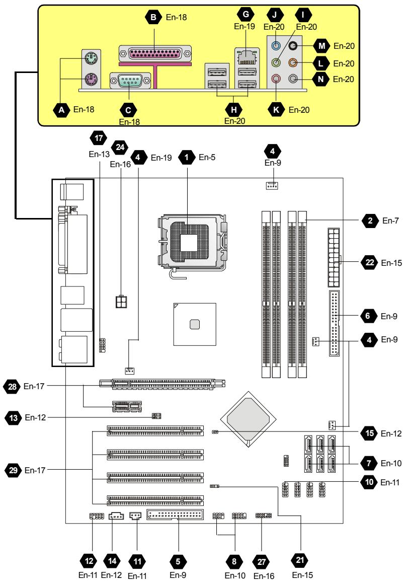
Quick Components Guide of P35 Neo3 Series (MS-7395 v1.X) Mainboard
Central Processing Unit: CPU
The mainland supports Intel® processor. The mainland uses a CPU socket called Socket 775 for easy CPU installation. If you do not have the CPU cooler, consult your dealer before turning on the computer.
For the latest information about CPU, please visit http://global.msi.com.tw/index.php? func=cpuform

Important
Overheating
Overheating will seriously damage the CPU and system. Always make sure the cooling fan can work properly to protect the CPU from overheating. Make sure that you apply an even layer of thermal paste (or thermal tape) between the CPU and the heatsink to enhance heat dissipation.
Replacing the CPU
While replacing the CPU, always turn off the ATX power supply or unplug the power supply's power cord from the grounded outlet first to ensure the safety of CPU.
Overclocking
This mainboard is designed to support overclocking. However, please make sure your components are able to tolerate such abnormal setting, while doing overclocking. Any attempt to operate beyond product specifications is not recommended. We do not guarantee the damages or risks caused by inadequate operation or beyond product specifications.
CPU & Cooler Installation Procedures for Socket 775
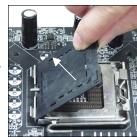
- The CPU socket has a plastic cap on it to protect the contact from damage. Before you have installed the CPU, always cover it to protect the socket pin.
- Remove the cap from lever hinge side.
- The pins of socket reveal.
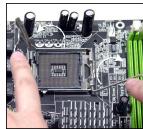
- Open the load lever.
- Lift the load lever up and open the load plate.
- After confirming the CPU direction for correct mating, put down the CPU in the socket housing frame. Be sure to grasp on the edge of the CPU base. Note that the alignment keys are matched.
- Visually inspect if the CPU is seated well into the socket. If not, take out the CPU with pure vertical motion and reinstall.
- Cover the load plate onto the package.
- Press down the load lever lightly onto the load plate, and then secure the lever with the hook under retention tab.
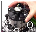
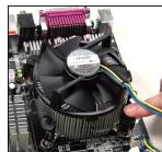
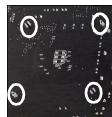
- Align the holes on the mainboard with the cooler. Push down the cooler until its four clips get wedged into the holes of the mainboard.
- Press the four hooks down to fasten the cooler. Then rotate the locking switch (refer to the correct direction marked on it) to lock the hooks.
- Turn over the mainboard to confirm that the clip-ends are correctly inserted.
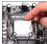
alignment key

Important
- Read the CPU status in BIOS.
- Whenever CPU is not installed, always protect your CPU socket pin with the plastic cap covered to avoid damaging.
- Mainboard photos shown in this section are for demonstration of the CPU/ cooler installation only. The appearance of your mainboard may vary depending on the model you purchase.
Memory
DDR2
Specification: 240-pin, 1.8v.
Single channel definition : All DIMM slots are GREEN color.
Dual channels definition : DIMM slot(s) on Channel A are marked in GREEN color. DIMM slot(s) on Channel B are marked in Orange color.
3 DDR3
Specification: 240-pin, 1.5v.
Single channel definition : All DIMM slots are SKYBLUE color.
Dual channels definition : DIMM slot(s) on Channel A are marked in SKYBLUE color. DIMM slot(s) on Channel B are marked in PINK color.


Important
- DDR3 memory modules are not interchangeable with DDR/DDR2 and the DDR3 standard is not backwards compatible. You should always install DDR3 memory modules in the DDR3 DIMM slots.
- In Dual-Channel mode, make sure that you install memory modules of the same type and density in different channel DIMM slots.
- To enable successful system boot-up, always insert the memory modules into the DIMM1 first.
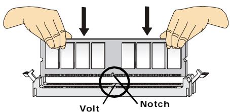
Installing Memory Modules
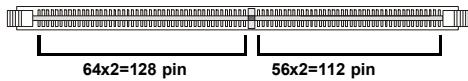
You can find the notch on the memory modules and the volt on the DIMM slots whether DDR or DDR2. Follow the procedures below to install the memory module properly.
- The memory modules has only one notch on the center and will only fit in the right orientation.
- Insert the memory module vertically into the DIMM slot. Then push it in until the golden finger on the memory module is deeply inserted in the DIMM slot.

Important
You can barely see the golden finger if the memory module is properly inserted in the DIMM slot.
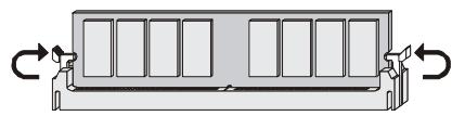
- The plastic clip at each side of the DIMM slot will automatically close.
Connectors, Jumpers, Slots
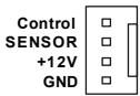
4 Fan Power Connectors
The fan power connectors support system cooling fan with +12V . The CPU FAN supports Smart FAN function. When connect the wire to the connectors, always take note that the red wire is the positive and should be connected to the +12V , the black wire is Ground and should be connected to GND. If the mainboard has a System Hardware Monitor chipset on-board, you must use a specially designed fan with speed sensor to take advantage of the fan control.
CPU FAN
- Please refer to the recommended CPU fans at processor's official website or consult the vendors for proper CPU cooling fan.
- CPUFAN supports fan control. You can install Dual Core Center utility that will automatically control the CPU fan speed according to the actual CPU temperature.
- Fan cooler set with 3 or 4 pins power connector are both available for CPUFAN.
5 Floppy Disk Drive Connector
This connector supports 360KB, 720KB, 1.2MB, 1.44MB or 2.88MB floppy disk drive.
IDE connector
This connector supports IDE hard disk drives, optical disk drives and other IDE devices.

Important
If you install two IDE devices on the same cable, you must configure the drives separately to Master/ Slave mode by setting jumpers. Refer to IDE device's documentation supplied by the vendors for jumper setting instructions.
Serial ATA Connector
This connector is a high-speed Serial ATA interface port. Each connector can connect to one Serial ATA device.


Important
Please do not fold the Serial ATA cable into 90-degree angle. Otherwise, data loss may occur during transmission.
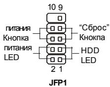
8 Front Panel Connectors
These connectors are for electrical connection to the front panel switches and LEDs. The JFP1 is compliant with Intel® Front Panel I/O Connectivity Design Guide.
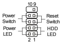
JFP1
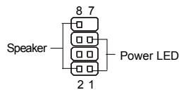
JFP2
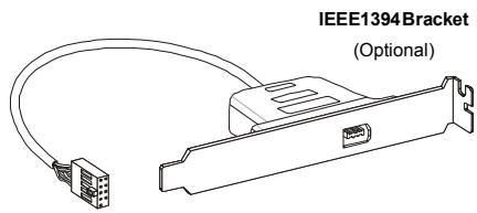
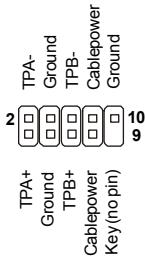
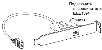
IEEE1394 Connector (Green)
This connector allows you to connect the IEEE1394 device via an optional IEEE1394 bracket.

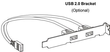
10 Front USB Connector (Yellow)
This connector, compliant with Intel® I/O Connectivity Design Guide, is ideal for connecting high-speed USB interface peripherals such as USB HDD, digital cameras, MP3 players, printers, modems and the like.
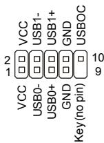

Important
Note that the pins of VCC and GND must be connected correctly to avoid possible damage.
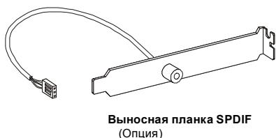
11 S/PDIF-Out Connector or S/PDIF-In Connector
This connector is used to connect S/PDIF (Sony & Philips Digital Interconnect Format) interface for digital audio transmission.

SPDIF Bracket (Optional)
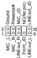
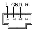
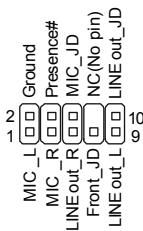
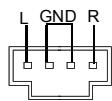
12 Front Panel Audio Connector (Azalia Spec)
This connector allows you to connect the front panel audio and is compliant with Intel® Front Panel I/O Connectivity Design Guide.
13 Hardware Overclock FSB Jumpers: JB1, JB2 (optional)
You can overclock the FSB to increase the processor frequency by changing the jumpers JB1 and JB2. Follow the instructions below to set the FSB.

JB1JB2
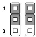
200 MHz
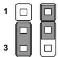
266 MHz
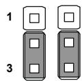
333 MHz

Important
Make sure that you power off the system before changing the jumpers
CD-In Connector
This connector is provided for external audio input.
15 Chassis Intrusion Connector
This connector connects to the chassis intrusion switch cable. If the chassis is opened, the chassis intrusion mechanism will be activated. The system will record this status and show a warning message on the screen. To clear the warning, you must enter the BIOS utility and clear the record.
1 CINTRU
2 GND
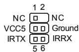
16 Infrared Module Connector
This connector allows you to connect to infrared module and is compliant with Intel® Front Panel I/O Connectivity Design Guide. You must configure the setting through the BIOS setup to use the infrared function.
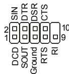
Serial Port Connector
This connector is a 16550A high speed communication port that sends/receives 16 bytes FIFOs. You can attach a serial device.
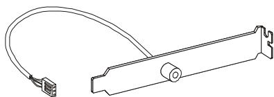
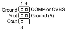
TV-Out Connector
This connector is for you to attach an optional TV-Out bracket that offers some types of TV-Out connectors. Select the appropriate one to connect to an television.
19 VolP Card Connector
This connector connects to the VoIP card. Please refer to the instruction of the VoIP card.

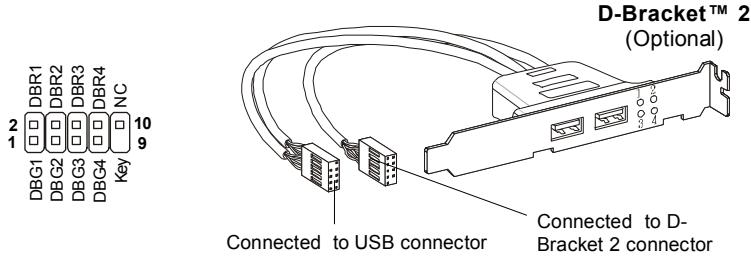
20 D-BracketTM 2 Connector
This connector is for you to connect to the D-Bracket™2 which integrates four LEDs and USB ports. It allows users to identify system problems through 16 various combinations of LED signals.
Red
| LED Signal | Description | LED Signal | Description |
| 1 2 3 4 | System Power ON The D-LED will hang here if the processor is damaged or not installed properly. | 1 2 3 4 | Initializing Video Interface This will start detecting CPU clock, checking type of video onboard. Then, detect and initialize the video adapter. |
| 1 2 3 4 | Early Chipset Initialization | 1 2 3 4 | BIOS Sign On This will start showing information about logo, processor brand name, etc... |
| 1 2 3 4 | Memory Detection Test Testing onboard memory size. The D-LED will hang if the memory module is damaged or not installed properly. | 1 2 3 4 | Testing Base and Extended Memory Testing base memory from 240K to 640K and extended memory above 1MB using various patterns. |
| 1 2 3 4 | Decompressing BIOS image to RAM for fast booting. | 1 2 3 4 | Assign Resources to all ISA. |
| 1 2 3 4 | Initializing Keyboard Controller. | 1 2 3 4 | Initializing Hard Drive Controller This will initialize IDE drive and controller. |
| 1 2 3 4 | Testing VGA BIOS This will start writing VGA sign-on message to the screen. | 1 2 3 4 | Initializing Floppy Drive Controller This will initialize Floppy Drive and controller. |
| 1 2 3 4 | Processor Initialization This will show information regarding the processor (like brand name, system bus, etc...) | 1 2 3 4 | BootAttempt This will set low stack and boot via INT 19h. |
| 1 2 3 4 | Testing RTC (Real Time Clock) | 1 2 3 4 | Operating System Booting |
21 Clear CMOS Jumper
There is a CMOS RAM onboard that has a power supply from an external battery to keep the data of system configuration. With the CMOS RAM, the system can automatically boot OS every time it is turned on. If you want to clear the system configuration, set the jumper to clear data.

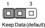
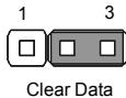

Important
You can clear CMOS by shorting 2-3 pin while the system is off. Then return to 1-2 pin position. Avoid clearing the CMOS while the system is on; it will damage the mainboard.
Power Supply Attachment
Before inserting the power supply connector, always make sure that all components are installed properly to ensure that no damage will be caused. All power connectors on the mainboard have to connect to the ATX power supply and have to work together to ensure stable operation of the mainboard.
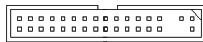
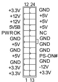
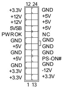
ATX 24-Pin Power Connector
This connector allows you to connect an ATX 24-pin power supply. To connect the ATX 24-pin power supply, make sure the plug of the power supply is inserted in the proper orientation and the pins are aligned. Then push down the power supply firmly into the connector.
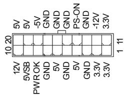
You may use the 20-pin ATX power supply as you like. If you'd like to use the 20-pin ATX power supply, please plug your power supply along with pin 1 & pin 13.
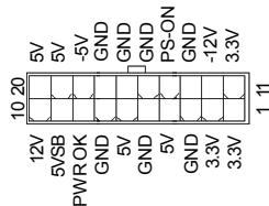
23 ATX 20-Pin Power Connector
This connector allows you to connect an ATX 20-pin power supply. To connect the ATX 20-pin power supply, make sure the plug of the power supply is inserted in the proper orientation and the pins are aligned. Then push down the power supply firmly into the
connector.
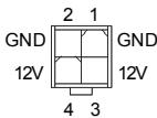
ATX 12V Power Connector (2x2-Pin)
This 12V power connector is used to provide power to the CPU.
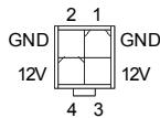
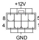
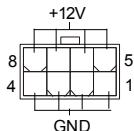
ATX 12V Power Connector (2x4-Pin)
This 12V power connector is used to provide power to the CPU.
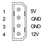
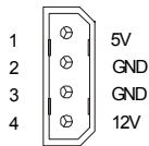
ATX 12V Power Connector (1x4-Pin)
This 12V power connector is used to provide power to the graphics card.
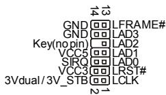
TPM Module Connector
This connector connects to a TPM (Trusted Platform Module) module (optional). Please refer to the TPM security platform manual for more details and usages.
PCI Express Slot (x16/ x4/ x1)
The PCI Express slot supports the PCI Express interface expansion card.
The PCI Express x 16 supports up to 4.0 GB/s transfer rate.
The PCI Express x 8 supports up to 2.0 GB/s transfer rate.
The PCI Express x 4 supports up to 1.0 GB/s transfer rate.
The PCI Express x 1 supports up to 250 MB/s transfer rate.

PCIExpress x 16 Slot
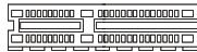
PCI Express x 4 Slot
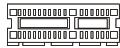
PCI Express x 1 Slot
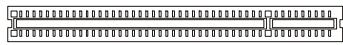
PCI (Peripheral Component Interconnect) Slot
The PCI slot supports LAN card, SCSI card, USB card, and other add-on cards that comply with PCI specifications.
30 AGP (Accelerated Graphics Port) Slot
The AGP slot allows you to insert the AGP graphics card. AGP is an interface specification designed for the throughput demands of 3D graphics. It introduces a 66MHz, 32-bit channel for the graphics controller to directly access main memory.
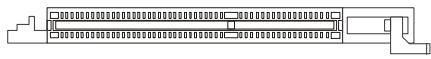

Important
When adding or removing expansion cards, make sure that you unplug the power supply first. Meanwhile, read the documentation for the expansion card to configure any necessary hardware or software settings for the expansion card, such as jumpers, switches or BIOS configuration.
Back Panel
A Mouse/Keyboard
The standard PS/2® mouse/keyboard DIN connector is for a PS/2® mouse/keyboard.
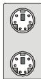
PS/2 Mouse connector (Green/ 6-pin female)
PS/2 Keyboard connector (Purple/ 6-pin female)
B Parallel Port
A parallel port is a standard printer port that supports Enhanced Parallel Port (EPP) and Extended Capabilities Parallel Port (ECP) mode.
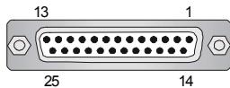
(25-pin female connector)
Serial Port
The serial port is a 16550A high speed communications port that sends/ receives 16 bytes FIFOs. You can attach a serial mouse or other serial devices directly to the connector.
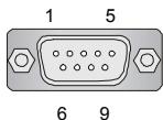
(9-Pin Male Connector)
VGA Port
The DB15-pin female connector is provided for monitor.
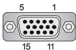
(15-Pin Female DIN Connector)
E DVI Port
The DVI (Digital Visual Interface) connector allows you to connect an LCD monitor. It provides a high-speed digital interconnection between the computer and its display device. To connect an LCD monitor, simply plug your monitor cable into the DVI connector, and make sure that the other end of the cable is properly connected to your monitor (refer to your monitor manual for more information.)
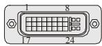

Important
Please note that the DVI connector does not support connecting the D-Sub to DVI converter.
F 1394 Port
The IEEE1394 port on the back panel provides connection to IEEE1394 devices.

G LAN
The standard RJ-45 LAN jack is for connection to the Local Area Network (LAN). You can connect a network cable to it.

| LED | Color | LED State | Condition |
| Left | Orange | Off | LAN link is not established. |
| On (steady state) | LAN link is established. | ||
| On (brighter & pulsing) | The computer is communicating with another computer on the LAN. | ||
| Right | Green | Off | 10 Mbit/sec data rate is selected. |
| On | 100 Mbit/sec data rate is selected. | ||
| Orange | On | 1000 Mbit/sec data rate is selected. |
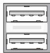
USB Port
The USB (Universal Serial Bus) port is for attaching USB devices such as keyboard, mouse, or other USB-compatible devices.
Audio Port Connectors
These audio connectors are used for audio devices. You can differentiate the color of the audio jacks for different audio sound effects.

Line-Out (Green) - Line Out, is a connector for speakers or headphones.
Line-In (Blue) - Line In / Side-Surround Out in 7.1 channel mode, is used for external CD player, tapeplayer or other audio devices.
MIC (Pink) - Mic In, is a connector for microphones.
CS-Out (Orange) - Center/ Subwoofer Out in 5.1/ 7.1 channel mode.
MS-Out (Black) - Rear-Surround Out in 4/5.1/7.1 channel mode.
SS-Out (Gray) - Side-Surround Out 7.1 channel mode.
Coaxial S/PDIF-out
This S/PDIF (Sony & Philips Digital Interconnect Format) connector is provided for digital audio transmission to external speakers through a coaxial cable.

Optical S/PDIF-out
This S/PDIF (Sony & Philips Digital Interconnect Format) connector is provided for digital audio transmission to external speakers through an optical fiber cable.

External SATA Port
This eSATA (External Serial ATA) port is used to connect the external SATA device. You can also use the optional external SATA cable to connect SATA device and eSATA port.

BIOS Setup
This chapter provides basic information on the BIOS Setup program and allows you to configure the system for optimum use. You may need to run the Setup program when:
- An error message appears on the screen during the system booting up, and requests you to run BIOS SETUP.
- You want to change the default settings for customized features.

Important
- The items under each BIOS category described in this chapter are under continuous update for better system performance. Therefore, the description may be slightly different from the latest BIOS and should be held for reference only.
- Upon boot-up, the 1st line appearing after the memory count is the BIOS version. It is usually in the format:
A7395IMS V1.0 070707 where:
1st digit refers to BIOS maker as A = AMI , W = AWARD , and P = PHOENIX .
2nd - 5th digit refers to the model number.
6th refers to the Chipset vender as A = ATi , I = Intel , V = VIA , N = Nvidia , U = UI .
7th - 8th digit refers to the customer as MS = all standard customers.
V1.0 refers to the BIOS version.
070707 refers to the date this BIOS was released.
Entering Setup
Power on the computer and the system will start POST (Power On Self Test) process. When the message below appears on the screen, press key to enter Setup.
Press DEL to enter SETUP
If the message disappears before you respond and you still wish to enter Setup, restart the system by turning it OFF and On or pressing the RESET button. You may also restart the system by simultaneously pressing <Ctrl> , <Alt> , and <Delete> keys.
Getting Help
After entering the Setup menu, the first menu you will see is the Main Menu.
Main Menu
The main menu lists the setup functions you can make changes to. You can use the arrow keys (↑↓) to select the item. The on-line description of the highlighted setup function is displayed at the bottom of the screen.
Sub-Menu
If you find a right pointer symbol (as shown in the right view) appears to the left of certain fields that means a sub-menu containing additional options can be launched from this field. You can use control keys ( ) to highlight the field and press
Primary IDE Master
Primary IDE Slave
Secondary IDE Master
Secondary IDE Slave
use the control keys to enter values and move from field to field within a sub-menu. If you want to return to the main menu, just press <Esc> .
General Help
The BIOS setup program provides a General Help screen. You can call up this screen from any menu by simply pressing <F1> . The Help screen lists the appropriate keys to use and the possible selections for the highlighted item. Press <Esc> to exit the Help screen.
The Main Menu
Once you enter AMI® or AWARD® BIOS CMOS Setup Utility, the Main Menu will appear on the screen. The Main Menu allows you to select from ten setup functions and two exit choices. Use arrow keys to select among the items and press
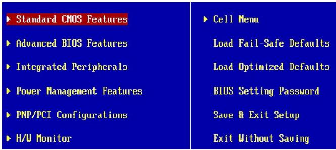
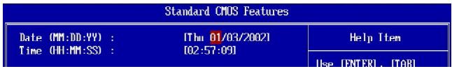
Standard CMOS Features
Use this menu for basic system configurations, such as time, date etc.
Advanced BIOS Features
Use this menu to setup the items of special enhanced features.
Integrated Peripherals
Use this menu to specify your settings for integrated peripherals.
Power Management Features
Use this menu to specify your settings for power management.
PNP/PCI Configurations
This entry appears if your system supports PnP/PCI.
H/W Monitor
This entry shows your PC health status.
Cell Menu
Use this menu to specify your settings for frequency/voltage control and overclocking.
Load Fail-Safe Defaults
Use this menu to load the default values set by the BIOS vendor for stable system performance.
Load Optimized Defaults
Use this menu to load the default values set by the mainboard manufacturer specifically for optimal performance of the mainboard.
BIOS Setting Password
Use this menu to set the Password.
Save & Exit Setup
Save changes to CMOS and exit setup.
Exit Without Saving
Abandon all changes and exit setup.
When enter the BIOS Setup utility, follow the processes below for general use.
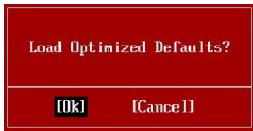
- Load Optimized Defaults: Use control keys ( ) to highlight the Load Optimized Defaults field and press
, a message as below appears:
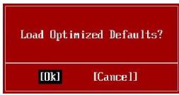
Press [Ok] to load the default settings for optimal system performance.
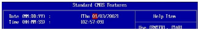
- Setup Date/ Time : Select the Standard CMOS Features and press
to enter the Standard CMOS Features-menu. Adjust the Date, Time fields.
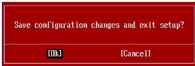
- Save & Exit Setup: Use control keys (↑ ↓) to highlight the Save & Exit Setup field and press
, a message as below appears:
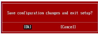
Press [Ok] to save the configurations and exit BIOS Setup utility.

Important
The configuration above are for general use only. If you need the detailed settings of BIOS, please see the manual in English version on MSI website.
Software Information
Take out the Driver/Utility CD that is included in the mainboard package, and place it into the CD-ROM driver. The installation will auto-run, simply click the driver or utility and follow the pop-up screen to complete the installation. The Driver/Utility CD contains the:
Driver menu - The Driver menu shows the available drivers. Install the driver by your desire and to activate the device.
Utility menu - The Utility menu shows the software applications that the mainboard supports.
WebSite menu- The WebSite menu shows the necessary websites.

Important
Please visit the MSI website to get the latest drivers and BIOS for better system performance.
P35 Neo3
Benutzerhandbuch
Deutsch
Spezifikationen
Prozessoren
FSB (Front-Side-Bus)
- 1333/1066/800MHz
Chipsatz
- North-Bridge: Intel® P35 Chipsat
- South-Bridge: Intel® ICH9 Base Chipsatz
Speicher
Specification: 240-Pin, 1.5v.
8 Frontpanel Anschlüsse
PCI (Peripheral Component Interconnect) Slot
30 AGP (Accelerated Graphics Port) Slot
Press DEL to enter SETUP
Primary IDE Master
Primary IDE Slave
Secondary IDE Master
Secondary IDE Slave
| Standard CMOS Features | Cell Menu |
| Advanced BIOS Features | Load Fail-Safe Defaults |
| Integrated Peripherals | Load Optimized Defaults |
| Power Management Features | BTOS Setting Password |
| PMP/PCI Configurations | Save & Exit Setup |
| H/M Monitor | Exit Without Saving |
Standard CMOS Features
Advanced BIOS Features
Integrated Peripherals
BIOS Setting Password
Central Processing Unit: CPU
Primary IDE Master
Primary IDE Slave
Secondary IDE Master
Secondary IDE Slave
| Standard CHUS Features | Cell Menu |
| Advanced BIOS Features | Load Fail-Safe Defaults |
| Integrated Peripherals | Load Optimized Defaults |
| Power Management Features | BIOS Setting Password |
| PNP/PCI Configurations | Save & Exit Setup |
| H/A Monitor | Exit Without Saving |
Standard CMOS Features
Advanced BIOS Features
Integrated Peripherals
BIOS Setting Password
Oba 3TN coeunHnteI INcNoJIb3yIOTc dIg IIOKIIIOHeH NHOJN INHINKaTOpOB, pacnoJooKeHHbIX Ha nepeJeHne naneHn KOpnya . CoeunHnteIb JFP1 COoTBETCTByet pykoBODCTBy Intel® Front Panel I/O design.

9 CoeinnHtelen IEEE1394 (3eJeHbI)
3TOT COeINHInTeIb N03BOJIAET NOKNIQUHTb NOPTBI IEEE 1394 Ha BblHOCHOI pHaHKe IEEE1394.
10 BbIOCHbIe nOpTbI USB 2.0 (KeIbI coeHNHTeB)
Pa3bEm, COBmecTmC pykoBOcTBom Intel® I/O Connectivity Design, nideaHbNo IЯн NOKJIuOHeNIA TAKNX BbICOKOCOPocCTbIX nepnΦeepnHbIX yctpoiCTB, KaK USB HDD, cnΦpOBbIe KAmepbl, MP3 nIeepbl, pInHTepbl, nIM noIo6hble.


BHMaHne
Pomnme, ymo 0o u36exaHue noepexdeHu, KOhmaKmbi VCC u GND doJXhbI 6bmb npabunbHo nokklupeHbI.
11 Coeinnhtelb Bxoda
3Ta coeINHtTeB nCnObl3yETc dIy noKnLIOeHn IInTEpeEca SPDIF (Sony & Philips Digital Interconnect Format) dIy nepeDaH 3Byka B uNΦpOBOM φopMaTe.

12 BbInocHoi pa3beM aydno (Azalia Spec)
3TOT coeHNHtIb N03BOJnEe TIOKIIOnuHTy BbIHOCHO pa3bem aydno Ha nepeDHei naHEn i COBmecTm C pykoBoDCTBOM Intel® Front Panel I/O Connectivity Design.
13пеклочаелпекимовFSB:JB1,JB2(onцоньнo)
Дя у breastyehnna yactotb paobt npoecccopa moxho pa3orha TS B c nomoohne nepekniuyatehen JB1 n JB2. Yto6b yctaHOBntb 3haueHne FSB bIwe, BocnoJIb3yIteCb n3O6paXeHHMa HIXke.

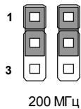
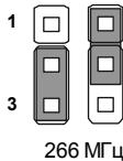
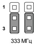

BhIMaHne
Ipeod nepeknoeHEm pexumoe FSBCnmoob nopekeLoyameneu, y6edumebc e mom, ymo cucmema biknoyeha.
14 Bxod aydno c CD
3TOT coeHNHTeNb npedHa3NaueH nIy IOnkIIOyeHn BHeuHero BBOda ayDIO.
IopKJIIOUeHHe NCTOUYHka IITaHnA
Ipeed nodknouehem pa3bema nitaHna, BO n36ekaHne nobpeKdHn 063aTeJbHO y6eintecb, YTO BCE KOMnoHeHTbl yCTaHOBHeHbl npabInbHo. Bce pa3beMbI numaHua doJxHbI bIbMb nokKnOeyHb I bIky numaHua ATX dIy oBeCneueHua cmaBunbHou pa6ombi cucmemHou nIambl.
22 24-KoHTaKTHbI pa3bEm nITaHnA TTX
3TOT pa3bem NO3BONJET NOKJIUChNTb 24-KoHTaKTbI INCTOCHN KITAHNA ATX.ДЯ NOKJIHcEHN INCTOCHNka y6eINTEcb, YTO erO pa3bem npabINbHO opneHTnpOBaH, 3aTeM OCTPOxH BCTaBte erO B OTBeTHyIO qAcTb. Bbl TakKe MOKe TE NcONlb3OBaTb 20 KOHTaKTbI ATX 6JOK NtAHNA.
23 20-KoHTaKTHbI pa3bem nHTaHn ATX
3TOT pa3bem IO3BONJREI NOKIIHOnTHb 20- KOHTAKTHbI INCTOCHNk NITAHnA TX.ДЯ NOKIIHcEHN ICTOCHNka y6eIntecb, yTO erO pa3bem npabINbHO opneHTnpOBaH, 3aTeM OCTPOXHO BCTaBbTe erO B OTBeTHyU qAcTb.
24 Pa3bem nHTaHnA TX 12V (2x2)
3ToT pa3bem 12V npedha3naeH dIJI nITaHn CPU.
25 Pa3bem nHTaHnA TX 12V (2x4)
3ToT pa3bem 12V npedHa3NaueH JIJI nITaHnCPU.
26 Pa3bem nHTaHnA TX 12V (1x4)
3ToT pa3bem 12V npedHa3NaueH dIe nITaHn rpaFnecko Kapbl.
27 KOHNHeKToT PTM MoUyIa
1a6ykea coomeemcmeyem u3oomoumenIO BIOS (A = AMI, W = AWARD u P = PHOENIX)
Cneoyuue 4 ucpbcoomemcmeyom Homepy modenu.
Cleedyuzaaybkyea obozhaaem nocmaeuka yuncema (A = ATi, I = Intel, V = VIA, N = Nvidia, U = ULi).
2 cneyuouue 6kyeobo3naHauaHm 3ka3uKa MS = cmaHdapmHbI 3ka3uK.
V1.0 coomoeemcmeyem Homepy eepcuu BIOS
070707 - dama ebinycka BIOS.
Bxod B pexm HactpoKn
BkIouHte nItaHne KOMnbIOTepa. Pn3TOM 3aNcyTntc npOceDpya POST (TeCT BkIoueHna NITaHn).Korda Ha 3KpaHe NOBHTc npNBedeHHOe HIXe coo6uHHe, HaxMITE KNaBnUy ДЯ BXOda B pexm HacTpoKn.
Press DEL to enter SETUP
Ecnn coo6eHnne nCue3IIO, a Bbl He yCneIIN HaxaTb KnaBnUy, nepe3anyCTnte CnCTEmy, BblKlHouN IN CHOBA BKlHouN INrTaHNe, INI HaxaB KHOKnY RESET. MoKHo, TaKHe, nepe3anyCTnTB CnCTEmy, HaxaB OndHOBpemEnHO KNaBnIn
PexkM HacTpoKn
BoiIaBpeKIM HAcTpoIKN, Bbl cpa3y yBnnte TnaBHOe MeHIO.
Main Menu (Главhoe мени)
Главhoe MeHIO COdepKHT CnncOK HAcTpoEK, KOtOpbIe Bbl MoKTe N3MeHNTb.ДлЯ Вьбopa moKHO nCNoIb3ObA Tb KJIaBUnu Co CtpeNkAmn(↑↓).СпразКа O bbl6paHHO NaCTPOJKe OTO6paXaETcB HnXHe YacTn 3KpaHa.
Повмени
Ecnn Bbl obhnapyknte, yTo cneBa OT nyHKta MeHIO IMeETcra 3nak npaboro yka3aTeJIa (kak noka3aHO cnpaBA) 3TO O3Naayet Hannuie NODMeHIO, CoepKaUero DOnONHtIbHbIe HactpoiKN KOTOpBle MOXHO CdelaTb B
Primary IDE Master
Primary IDE Slave
Secondary IDE Master
Secondary IDE Slave
3TOM nyHKTe. IcnoIb3yIte ynpabJnOuIe KnaBnI (↑↓)ДЯ Bb6opa, a 3aTe m HaxmTe
Подробна справka
B pexime hactpoikn BIOS nmeetcra Bo3MOxHocTB npuyehn noDpO6HO cnpaBKn. Ee moXho Bb3BaTb n3 JIO6oR o MeHIO npocTbIM HaxaTneM
Main Menu (Главhoe MeHIO)
Пив BXODE b pexim hacpoiKNBIOS ot AMI® nIIN AWARDHa 3Kpahe oTObpaKaetcrgnabHoe MeHIO.ΓIaBHOe MeHIO nO3BOJraE T Bb6paTb DecaTb FyHKUIN HAcToPoiKn ImMeET dBa BapnaHTa BbIXoJa.ДЯп epemeueHn OpykTAM NcIOnb3yOTcR KJIaBnSi co cTrpeKamN
| Standard BIOS Features | Cell Menu |
| Advanced BIOS Features | Load Fail-Safe Defaults |
| Integrated Peripherals | Load Optimized Defaults |
| Power Management Features | BIOS Setting Password |
| PNP/PCI Configurations | Save & Exit Setup |
| H/W Monitor | Exit Without Saving |
Standard CMOS Features (CtahapThbIe yHKcIM CMOS)
3To MeHIOI03BOJAEYCTAHOBHTb OCHOBHbIE npaMeTpbl KOHpypaunn CnCTembl (DaTy, BpeMn T.I.)
Advanced BIOS Features (Дононтеловie Функции BIOS)
3TO MeHIO nCnOlb3yETcI dIa HAcTPOkN CneuaNaBbHbIX yHKuBIOS.
Integrated Peripherals (BcTpoEHHbIe nepuΦepnHbIe ycTpoIcTa)
3To MeHIO nCnOJIb3yeTcA dIy HAcTpoKn npaMeTPOB BCTpoEHbIX nepuΦepnHbIX yCTPOINCTB.
Power Management Setup (Hactpoika ynpablenia nitaHnem)
3To MeHIO N03B0Jare 3aadTb npaMeTpbl ynpaBHeHn nTuHnem CnCTeMbI.
PNP/PCI Configurations (KoHpyaun PNP/PCI)
3TOT nyHKT noBnIeTcR, ecIn cnCTema noDepKnBaet PnP/PCI.
H/W Monitor (MoHTop annapaTHo yactn)
3TOT nyHKT OTO6paxaet COCTOJHne annapathou qactn PK.
Cell Menu (MeHIO y3na "Cell")
3To MeHIO N03B0JAEYnpabnTb TAKTOBIMN YacTOTAMN HAnpJxKeHnMn npn pa3roHe CNTEmbl.
Load Setup Default (YctaHObka 3NaeHn no yMOnuHaHIO)
3TOT nyHKT MeHIO BIOS'a nCNoIb3yETcДЯ 3aRpy3Kn 3HaueHn npaMeTpOB CnCTeMbI, o6ecneuBaIoUxN HauBoJe e cAunbHyO pa6OtY.
Load Optimized Defaults (YCTaHOBnTb ONTmAbHbHe HAcTpoKn)
3To MeHIO NcNoB3yeTcIy YCTaHOBKn HAcTpoE K3rOToBnTeJIg IJn ONtMaJIbHOINPOUNBOIDHTeJIbHOCTN CNTeMHoN PJIaTbl.
BIOS Setting Password (Паров досун Книсторikam BIOS)
3To MeHIO nCNoJIb3YeTcR, YTO6bl 3aJaTb npoJIb.
Save & Exit Setup (BbIXoD c coxpaHennm HactpoeK)
3anncb n3mehenB CMOS n BbyoD n3 pejima hactpoKn.
Exit Without Saving (BbIXoI 6e3 coxpaHnna)
OTmeHa BCex n3MeHenH N BbIXoN i3 peXmHa NaCTpoKn.
B obuem clyuae, haxoJcB b peKIme HacTpoKn BIOS, peKOMeHdyetc BblOnHnTb cIeDyUOune DeiCTBnI.
- Load Optimized Defaults (YCTaHOBnTB ONTNMaJIbHbIe HaCTpOKn): KJIaBnAmu ynpaBHeHn (↑↓) BbIepeNte NyKt Load Optimized Defaults n HaxMnTe
, NOBtCra CJeDyUoOee Coo6ZeHne:
Haxmte [Ok] yctahOBKn HactpoeK ONTImaIbHOI pON3BOJNTeJIbHOCTN.
- Setup Date/ Time (YcTaHOBKa DaTbI/BpeMeHn): BbIbepnte Standard CMOS Features (CtAndapThBieФyHKuIMn CMOS)инakmite
ДЯ BXOJa B MeHIO.YcTaHOBTe DaTyИВрмЯВCOOTBeTCTByUOxIN NOJAX.
- Save & Exit Setup (BbIXoJc coxpaHeHem n3MeHeHn): KnabuIaMyn npabInenna (↑↓) BbI6epnte nyKt Save & Exit Setup n haxmnte
, no8BNTcra cIeNyUoJeec coo6uHne:
HaxmTe [Ok] nIa coXpaHeHnKoHpIgpyaunn N BbIXOda n3 peXnMa hAcTpoiKN BIOS.

BHMaHne
IpuueeHnae bIwe konfuaypauu naodxodum dnooepao npumehenra. Ecnu Je aam mpebyomc6 boee mohque hacmpouku BIOS, obpamumecb K anluickou eepcu pykoedcmea ha ee6-caume MSI
CBeDeHnO npoPamMHom oBecneHnn
YctaHOBtBe B CD npBOD nck Driver/Utility (JaPauBepbI yTuNTnTbI) n3 KOMNKeTa NOCTABKn CnCTeMHoN PNaTbI. ABToMaTHuCeCK 3aNyCTuTcR INHCTaANLzra. IpocTo HaxMIte Ha Na3BaHne dpaBepa/ yTuNTnTbI u cNeDuYte INHCTpyKUmaR Ha 3kpaHe dla 3aBepSeHnRAHCTaANLzmu. Dnck Driver/Utility codepknt:
Driver menu (MeHIO dpaBepOB) - I3 IMeUxxCs dpaBepOB Bb6epnte HxKbI dJa AKTUBaUN yCTpOJCTBA.
Utility menu (MeHIO yTnIIN) - CoepKNT npKJaIbIe nporpaMMbl nIaepKcN CnCTEMHOI PaTbI.
WebSite menu (MeHIO Be6caTOB) - CopeKNT cncocn Heo6xOIMbIX Be6caTOB.

BhimaHne
IpuueeHnae bIwe konfuaypauu naoxoum dnoeao npumehenu. Ecnu Je aam mpebyomc6 boee mohque hacmpouku BIOS, obpamumecb K anuiickou eepcu pykoedcmea ha ee6-caume MSI