
G52-73921XK - Laptop MSI - Free user manual and instructions
Find the device manual for free G52-73921XK MSI in PDF.

| Product Type | Motherboard |
| Form Factor | ATX (30.5 cm x 23.6 cm) |
| CPU Socket | LGA775 |
| Supported Processors | Intel Core2 Quad, Core2 Duo, Pentium E2XXX, Celeron 4XX |
| Supported FSB | 1333/1066/800 MHz |
| Chipset | Northbridge Intel P31/G31, Southbridge Intel ICH7R/ICH7 |
| Memory Type | DDR2 |
| Memory Speed | 800/667 MHz |
| Maximum Memory Capacity | 4 GB (4 x DIMM) |
| Expansion Slots | 1x PCI Express x16, 2x PCI Express x1, 3x PCI |
| Audio | Realtek ALC888, 8 channels, HD Audio compliant |
| Network | Realtek RTL8111C/RTL8111B Gigabit Ethernet |
| Storage | 4x SATA II (3 Gb/s), 1x IDE Ultra DMA 66/100, 1x FDD |
| USB Ports | 4 rear USB ports + 2 front headers (up to 8 ports) |
| Rear I/O Ports | 1x PS/2 mouse, 1x PS/2 keyboard, 1x parallel, 1x serial, 1x RJ45, 6x audio jacks |
| Internal Connectors | 2x USB, 1x CD-IN, 1x S/PDIF out, 1x front audio, 1x chassis intrusion, 1x IEEE 1394 (optional), 1x TPM |
| Power Supply | ATX 24-pin + CPU 12V 4-pin |
| Overclocking | FSB jumpers (200/266/333 MHz) |
| Hardware Monitoring | CPU temperature, voltages, fan speeds, Smart Fan |
Frequently Asked Questions - G52-73921XK MSI
User questions about G52-73921XK MSI
0 question about this device. Answer the ones you know or ask your own.
Ask a new question about this device
Download the instructions for your Laptop in PDF format for free! Find your manual G52-73921XK - MSI and take your electronic device back in hand. On this page are published all the documents necessary for the use of your device. G52-73921XK by MSI.
USER MANUAL G52-73921XK MSI
The material in this document is the intellectual property of MICRO-STAR INTERNATIONAL. We take every care in the preparation of this document, but no guarantee is given as to the correctness of its contents. Our products are under continual improvement and we reserve the right to make changes without notice.
Trademarks
All trademarks are the properties of their respective owners.
NVIDIA, the NVIDIA logo, DualNet, and nForce are registered trademarks or trademarks of NVIDIA Corporation in the United States and/or other countries.
AMD, Athlon™, Athlon™ XP, Thoroughbred™, and Duron™ are registered trademarks of AMD Corporation.
Intel® and Pentium® are registered trademarks of Intel Corporation.
PS/2 and OS®/2 are registered trademarks of International Business Machines Corporation.
Windows® 95/98/2000/NT/XP are registered trademarks of Microsoft Corporation.
Netware® is a registered trademark of Novell, Inc.
Award® is a registered trademark of Phoenix Technologies Ltd.
AMI^® is a registered trademark of American Megatrends Inc.
Revision History
Revision
V2.1
Revision History
First Release for Europe
Date
September 2008
Technical Support
If a problem arises with your system and no solution can be obtained from the user's manual, please contact your place of purchase or local distributor. Alternatively, please try the following help resources for further guidance.
Visit the MSI website for FAQ, technical guide, BIOS updates, driver updates, and other information: http://global.msi.com.tw/index.php? func=service
Contact our technical staff at: http://ocss.msi.com.tw
-
Always read the safety instructions carefully.
-
Keep this User's Manual for future reference.
-
Keep this equipment away from humidity.
-
Lay this equipment on a reliable flat surface before setting it up.
-
The openings on the enclosure are for air convection hence protects the equipment from overheating. DO NOT COVER THE OPENINGS.
-
Make sure the voltage of the power source and adjust properly 110/220V before connecting the equipment to the power inlet.
-
Place the power cord such a way that people can not step on it. Do not place anything over the power cord.
-
Always Unplug the Power Cord before inserting any add-on card or module.
-
All cautions and warnings on the equipment should be noted.
-
Never pour any liquid into the opening that could damage or cause electrical shock.
-
If any of the following situations arises, get the equipment checked by a service personnel:
† The power cord or plug is damaged.
† Liquid has penetrated into the equipment.
† The equipment has been exposed to moisture.
† The equipment has not work well or you can not get it work according to User's Manual.
† The equipment has dropped and damaged.
† The equipment has obvious sign of breakage.
- DONOT LEAVE THIS EQUIPMENT INAN ENVIRONMENT UNCONDITIONED, STORAGE TEMPERATURE ABOVE 60^ (140°F), IT MAY DAMAGE THE EQUIPMENT.

CAUTION: Danger of explosion if battery is incorrectly replaced. Replace only with the same or equivalent type recommended by the manufacturer.

警告使用者:
For better environmental protection, waste batteries should be collected separately for recycling or special disposal.
This equipment has been tested and found to comply with the limits for a Class B digital device, pursuant to Part


N1996
15 of the FCC Rules. These limits are designed to provide reasonable protection against harmful interference in a residential installation. This equipment generates, uses and can radiate radio frequency energy and, if not installed and used in accordance with the instructions, may cause harmful interference to radio communications. However, there is no guarantee that interference will not occur in a particular installation. If this equipment does cause harmful interference to radio or television reception, which can be determined by turning the equipment off and on, the user is encouraged to try to correct the interference by one or more of the measures listed below.
† Reorient or relocate the receiving antenna.
† Increase the separation between the equipment and receiver.
Connect the equipment into an outlet on a circuit different from that to which the receiver is connected.
Consult the dealer or an experienced radio/television technician for help.
Notice 1
The changes or modifications not expressly approved by the party responsible for compliance could void the user's authority to operate the equipment.
Notice 2
Shielded interface cables and A.C. power cord, if any, must be used in order to comply with the emission limits.
VOIR LANOTICE D'INSTALLATIONAVANT DE RACCORDERAU RESEAU.

This device complies with Part 15 of the FCC Rules. Operation is subject to the following two conditions:
(1) this device may not cause harmful interference, and
(2) this device must accept any interference received, including interference that may cause undesired operation.
ENGLISH
To protect the global environment and as an environmentalist, MSI must remind you that...
Under the European Union ("EU") Directive on Waste Electrical and Electronic Equipment, Directive 2002/96/EC, which takes effect on August 13, 2005, products of "electrical and electronic equipment" cannot be discarded as municipal waste anymore and manufacturers of covered electronic equipment will be obligated to take back such products at the end of their useful life. MSI will comply with the product take back requirements at the end of life of MSI-branded products that are sold into the EU. You can return these products to local collection points.
DEUTSCH
Safety Instructions . 3
FCC-B Radio Frequency Interference Statement iv
WEEE (Waste Electrical and Electronic Equipment) Statement
English En-1
Mainboard Specifications En-2
Quick Components Guide En-4
CPU (Central Processing Unit) En-5
Memory. En-9
Power Supply. En-11
Back Panel En-12
Connectors . En-14
Jumpers En-21
Slots En-22
BIOS Setup. En-23
Software Information En-28
Deutsch . De-1
CPU (Central Processing Unit) En-5
Speicher En-9
Mainboard Specifications
Processor Support
- Intel® Core™2 Quad, Core™2 Duo, Pentium® E2XXX and Celeron® 4XX processor in the LGA775 package
(For the latest information about CPU, please visit http://global.msi.com.tw/index.php?func=cpuform)
Supported FSB
- 1333/ 1066/ 800 MHz
Chipset
- North Bridge: Intel® P31/ G31 chipset
- South Bridge: Intel® ICH7R/ ICH7 chipset
Memory Support
- DDR2 800/667 SDRAM (4GB Max)
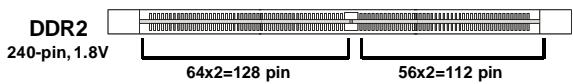
- 4 DDR2 DIMMs (240pin/1.8V)
(For more information on compatible components, please visit http://global.msi.com.tw/index.php?func=testreport)
LAN
- Supports PCI Express LAN 10/ 100/ 1000 Fast Ethernet by Realtek® RTL8111C/ RTL8111B (Optional)
IEEE 1394 (Optional)
- Chip integrated by VIA® VT6308P
- Transfer rate is up to 400 Mbps
Audio
- Chip integrated by Realtek® ALC888
- Flexible 8-channel audio with jack sensing
- Compliant with Azalia 1.0 Spec
- Meet Microsoft® Windows® Vista™ Premium Spec
IDE
-1 IDE port by Intel® ICH7R/ICH7
Supports Ultra DMA 66/100 mode
- Supports PIO and Bus Master operation mode
SATA
- 4 SATA II ports by Intel® ICH7R/ICH7
Supports four SATA devices - Supports storage and data transfers at up to 3Gb/s
RAID
- Supports RAID 0/1/0+1/5 mode by Intel® ICH7R
Floppy
- 1 floppy port
- Supports 1 FDD with 360KB, 720KB, 1.2MB, 1.44MB and 2.88MB
Connectors
Back panel
- 1 PS/2 mouse port
- 1 PS/2 keyboard port
- 1 parallel port
- 1 serial port
- 1 LAN jack
- 4 USB ports
- 6 audio jacks
- On-Board Pinheaders
- 2 USB pinheaders
- 1 CD-in pinheader
- 1 S/PDIF-out pinheader
- 1 front panel audio pinheader
- 1 chassis intrusion switch pinheader
- 1 1394 pinheader (Optional)
- 1 JTPM module connector
Slots
- 1 PCI Express x16 slot
- 2 PCI Express x1 slots
- 3 PCI slots (support 3.3V/5V PCI bus Interface)
Form Factor
-ATX(30.5cm×23.6cm)
Mounting
- 6 mounting holes
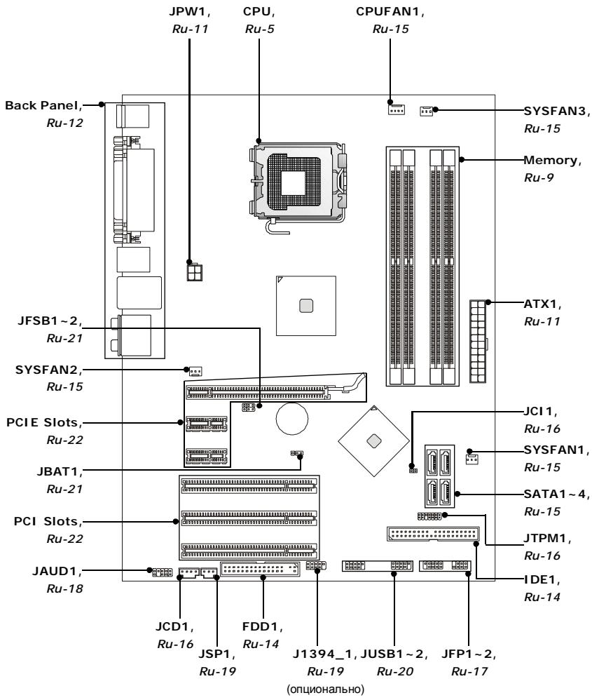
Quick Components Guide
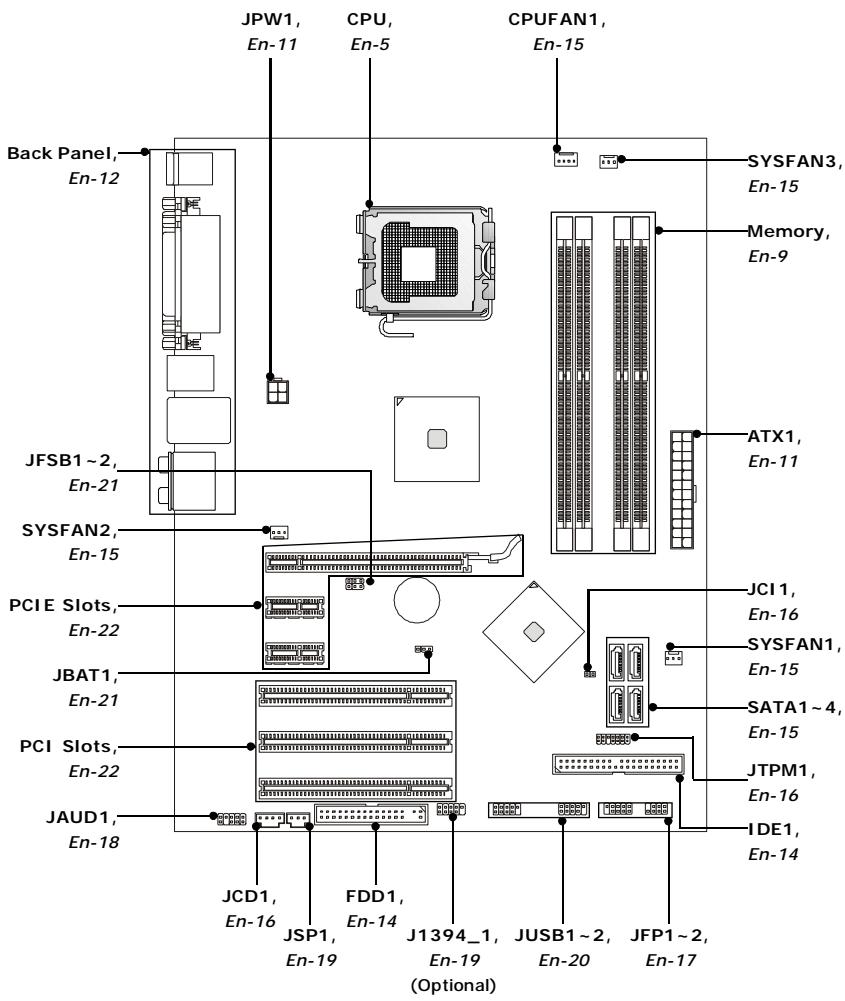
CPU (Central Processing Unit)
When you are installing the CPU, make sure to install the cooler to prevent overheating. If you do not have the CPU cooler, consult your dealer before turning on the computer.
For the latest information about CPU, please visit http://global.msi.com.tw/index.php?func=cpuform

Important
Overheating
Overheating will seriously damage the CPU and system. Always make sure the cooling fan can work properly to protect the CPU from overheating. Make sure that you apply an even layer of thermal paste (or thermal tape) between the CPU and the heatsink to enhance heat dissipation.
Replacing the CPU
While replacing the CPU, always turn off the ATX power supply or unplug the power supply's power cord from the grounded outlet first to ensure the safety of CPU.
Overclocking
This mainboard is designed to support overclocking. However, please make sure your components are able to tolerate such abnormal setting, while doing overclocking. Any attempt to operate beyond product specifications is not recommended. We do not guarantee the damages or risks caused by inadequate operation or beyond product specifications.
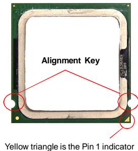
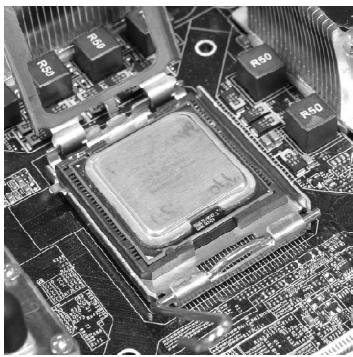
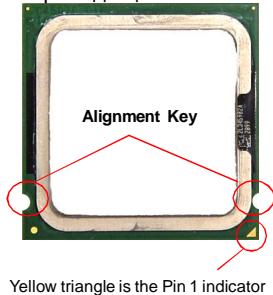
Introduction to LGA 775 CPU
The pin-pad side of LGA 775 CPU.
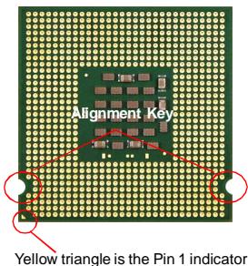
The surface of LGA 775 CPU. Remember to apply some thermal paste on it for better heat dispersion.
CPU & Cooler Installation
When you are installing the CPU, make sure the CPU has a cooler attached on the top to prevent overheating. Meanwhile, do not forget to apply some thermal paste on CPU before installing the heat sink/cooler fan for better heat dispersion.
Follow the steps below to install the CPU & cooler correctly. Wrong installation will cause the damage of your CPU & mainboard.
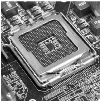
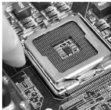
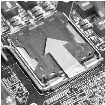
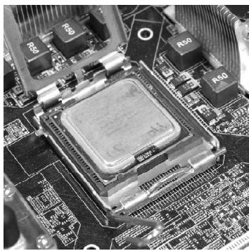
- The CPU socket has a plastic cap on it to protect the contact from damage. Before you install the CPU, always cover it to protect the socket pin.
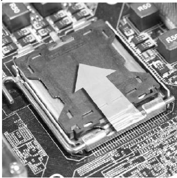
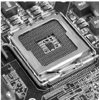
- The pins of socket reveal.
- Remove the cap from lever hingeside (as the arrow shows).
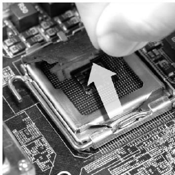
- Open the load lever.

Important
- Confirm if your CPU cooler is firmly installed before turning on your system.
- Do not touch the CPU socket pins to avoid damaging.
-
The availability of the CPU land side cover depends on your CPU packing.
-
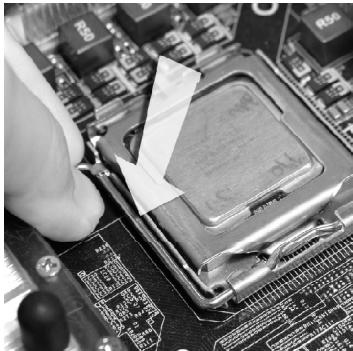
Lift the load lever up and open the load plate.

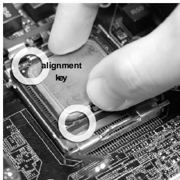
- Visually inspect if the CPU is seated well into the socket. If not, take out the CPU with pure vertical motion and reinstall.
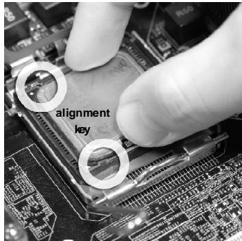
- After confirming the CPU direction for correct mating, put down the CPU in the socket housing frame. Be sure to grasp on the edge of the CPU base. Note that the alignment keys are matched.
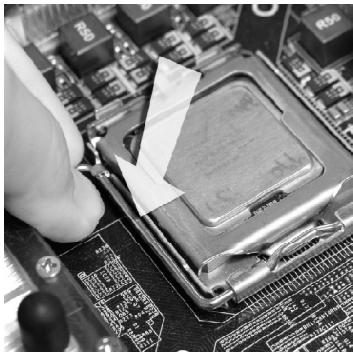
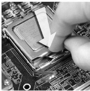
- Cover the load plate onto the package.

- Press down the load lever lightly onto the load plate, and then secure the lever with the hook under retention tab.
-
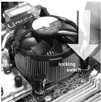
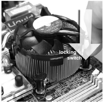
Press the four hooks down to fasten the cooler. Then rotate the locking switch (refer to the correct direction marked on it) to lock the hooks.
-
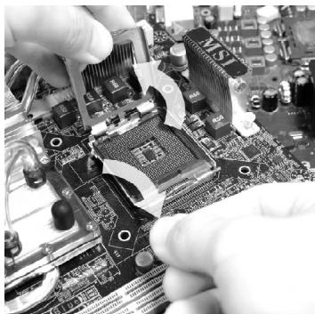
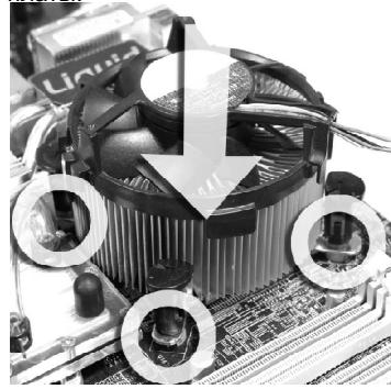
Align the holes on the mainboard with the heatsink. Push down the cooler until its four clips get wedged into the holes of the mainboard.

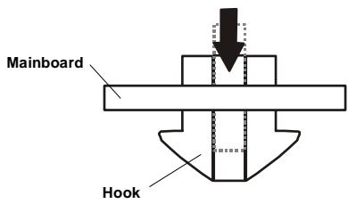
- Turn over the mainboard to confirm that the clip-ends are correctly inserted.


Important
- Read the CPU status in BIOS (Chapter 3).
- Whenever CPU is not installed, always protect your CPU socket pin with the plastic cap covered (shown in Figure 1) to avoid damaging.
- Mainboard photos shown in this section are for demonstration of the CPU/ cooler installation only. The appearance of your mainboard may vary depending on the model you purchase.
Memory
These DIMM slots are used for installing memory modules.
(For more information on compatible components, please visit http://global.msi.com.tw/index.php?func=testreport)
Single-Channel: All DIMMs in GREEN
Dual-Channel: Channel A in GREEN; Channel B in ORANGE
Due to chipset limitations, to enable dual channel mode or single channel mode, installing memory modules should refer to the following table.
Memory Installation Combination
(SS: single side, DS: double side, X: none installed memory)
| DIMM1 | DIMM2 | DIMM3 | DIMM4 | ||
| Dual Channel Mode | Combination1 | DS/SS | X | DS/SS | X |
| Combination2 | DS/SS | X | X | DS/SS | |
| Combination3 | X | DS/SS | DS/SS | X | |
| Combination4 | X | DS/SS | X | DS/SS | |
| Combination5 | SS | SS | SS | SS | |
| Single Channel Mode | Combination1 | DS/SS | X | X | X |
| Combination2 | X | DS/SS | X | X | |
| Combination3 | X | X | DS/SS | X | |
| Combination4 | X | X | X | DS/SS | |
| Combination5 | SS | SS | X | X | |
| Combination6 | X | X | SS | SS | |
| Combination7 | SS | SS | DS/SS | X | |
| Combination8 | SS | SS | X | DS/SS | |
| Combination9 | DS/SS | X | SS | SS | |
| Combination10 | X | DS/SS | SS | SS | |
Installing Memory Modules
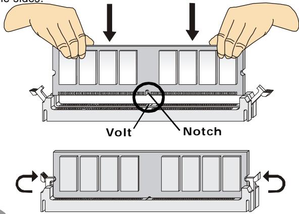
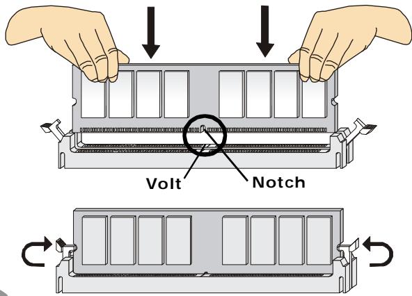
- The memory module has only one notch on the center and will only fit in the right orientation.
- Insert the memory module vertically into the DIMM slot. Then push it in until the golden finger on the memory module is deeply inserted in the DIMM slot. The plastic clip at each side of the DIMM slot will automatically close when the memory module is properly seated.

Important
You can barely see the golden finger if the memory module is properly inserted in the DIMM slot.
- Manually check if the memory module has been locked in place by the DIMM slot clips at the sides.

Important
- DDR2 memory modules are not interchangeable with DDR and the DDR2 standard is not backwards compatible. You should always install DDR2 memory modules in the DDR2 DIMM slots.
- In Dual-Channel mode, make sure that you install memory modules of the same type and density in different channel DIMM slots.
- To enable successful system boot-up, always insert the memory modules into the DIMM1 first.
- Due to the chipset resource deployment, the system density will only be detected up to 3+GB (not full 4GB) when each DIMM is installed with a 1GB memory module.
Power Supply
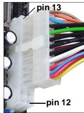
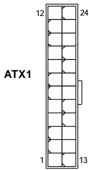
ATX 24-Pin Power Connector: ATX1
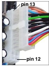
This connector allows you to connect an ATX 24-pin power supply. To connect the ATX 24-pin power supply, make sure the plug of the power supply is inserted in the proper orientation and the pins are aligned. Then push down the power supply firmly into the connector. You may use the 20-pin ATX power supply as you like. If you'd like to use the 20-pin ATX power supply, please plug your power supply along with pin 1 & pin 13 (refer to the image at the right hand). There is also a foolproof design on pin 11, 12, 23 & 24 to avoid wrong installation.
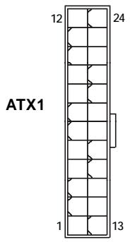
Pin Definition
| PIN | SIGNAL | PIN | SIGNAL |
| 1 | +3.3V | 13 | +3.3V |
| 2 | +3.3V | 14 | -12V |
| 3 | GND | 15 | GND |
| 4 | +5V | 16 | PS-ON# |
| 5 | GND | 17 | GND |
| 6 | +5V | 18 | GND |
| 7 | GND | 19 | GND |
| 8 | PWROK | 20 | Res |
| 9 | 5VSB | 21 | +5V |
| 10 | +12V | 22 | +5V |
| 11 | +12V | 23 | +5V |
| 12 | +3.3V | 24 | GND |
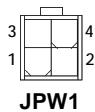
ATX 12V Power Connector: JPW1
This 12V power connector JPW1 is used to provide power to the CPU.
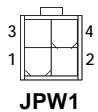
Pin Definition
| PIN | SIGNAL |
| 1 | GND |
| 2 | GND |
| 3 | 12V |
| 4 | 12V |

Important
- Make sure that all the connectors are connected to proper ATX power supplies to ensure stable operation of the mainboard.
- Power supply of 350 watts (and above) is highly recommended for system stability.
Back Panel
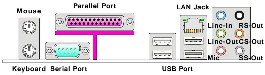
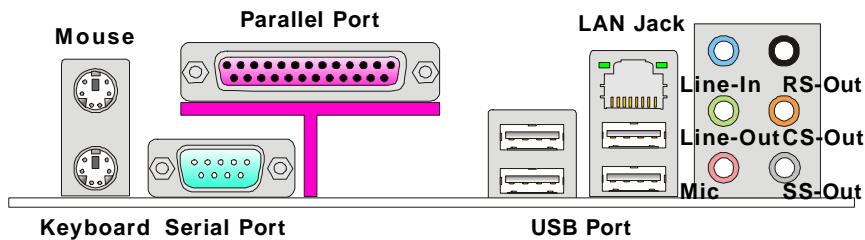
Mouse/Keyboard
The standard PS/2® mouse/keyboard DIN connector is for a PS/2® mouse/keyboard.
Parallel Port
A parallel port is a standard printer port that supports Enhanced Parallel Port (EPP) and Extended Capabilities Parallel Port (ECP) mode.
▶ Serial Port
The serial port is a 16550A high speed communications port that sends/ receives 16 bytes FIFOs. You can attach a serial mouse or other serial devices directly to the connector.
USB Port
The USB (Universal Serial Bus) port is for attaching USB devices such as keyboard, mouse, or other USB-compatible devices.
LAN Jack
The standard RJ-45 LAN jack is for connection to the Local Area Network (LAN). You can connect a network cable to it.

| LED | Color | LED State | condition |
| Left | Yellow | Off | LAN link is not established. |
| On (steady state) | LAN link is established. | ||
| On (brighter & pulsing) | The computer is communicating with another computer on the LAN. | ||
| Right | Green | Off | 10 Mbit/sec data rate is selected. |
| On | 100 Mbit/sec data rate is selected. | ||
| Orange | On | 1000 Mbit/sec data rate is selected. |
Audio Ports
These audio connectors are used for audio devices. You can differentiate the color of the audio jacks for different audio sound effects.
■ Line-In (Blue) - Line In, is used for external CD player, tapeplayer or other audio devices.
Line-Out (Green) - Line Out, is a connector for speakers or headphones.
■ Mic (Pink) - Mic, is a connector for microphones.
■ RS-Out (Black) - Rear-Surround Out in 4/5.1/7.1 channel mode.
CS-Out (Orange) - Center/ Subwoofer Out in 5.1/7.1 channel mode.
SS-Out (Gray) - Side-Surround Out 7.1 channel mode.
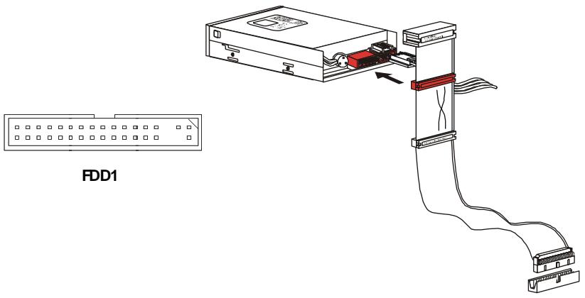
Connectors
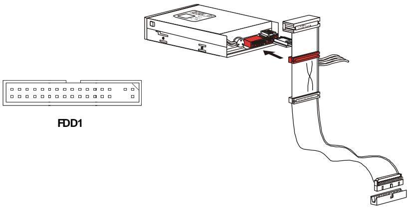
Floppy Disk Drive Connector: FDD1
This connector supports 360KB, 720KB, 1.2MB, 1.44MB or 2.88MB floppy disk drive.
IDE Connector: IDE1
This connector supports IDE hard disk drives, optical disk drives and other IDE devices.
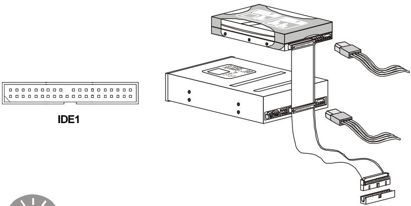

Important
If you install two IDE devices on the same cable, you must configure the drives separately to master / slave mode by setting jumpers. Refer to IDE device's documentation supplied by the vendors for jumper setting instructions.
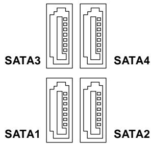
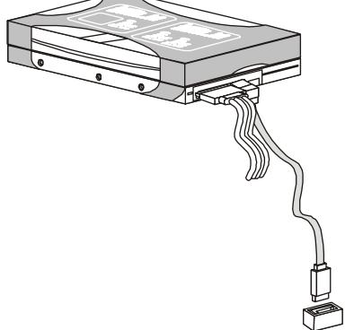
Serial ATA Connector: SATA1/ SATA2/ SATA3/ SATA4
This connector is a high-speed Serial ATA interface port. Each connector can connect to one Serial ATA device.
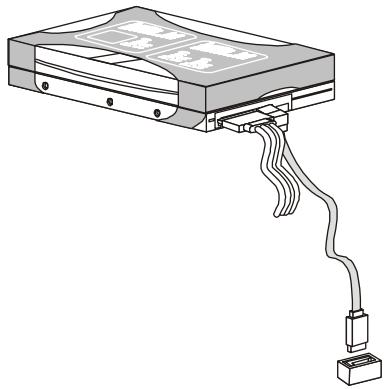

Important
Please do not fold the Serial ATA cable into 90-degree angle. Otherwise, data loss may occur during transmission.
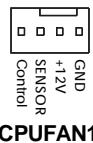
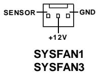
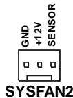
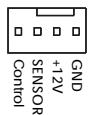
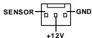
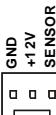
Fan Power Connectors: CPUFAN1/ SYSFAN1/ SYSFAN2/ SYSFAN3
The fan power connectors support system cooling fan with +12V . When connecting the wire to the connectors, always note that the red wire is the positive and should be connected to the +12V ; the black wire is Ground and should be connected to GND. If the mainboard has a System Hardware Monitor chipset on-board, you must use a specially designed fan with speed sensor to take advantage of the CPU fan control.

Important
- Please refer to the recommended CPU fans at processor's official website or consult the vendors for proper CPU cooling fan.
- Fan cooler set with 3 or 4 pins power connector are both available for CPUFAN1.
- CPUFAN1 supports fan control. You can setup it in H/W Monitor of BIOS Setup. You can install Dual Core Center utility that will automatically control the CPU fan speed according to the actual CPU temperature.
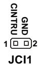
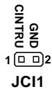
Chassis Intrusion Switch Connector: JCI1
This connector connects to a 2-pin chassis switch. If the chassis is opened, the switch will be short. The system will record this status and show a warning message on the screen. To clear the warning, you must enter the BIOS utility and clear the record.
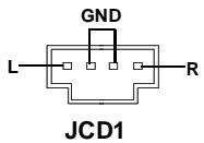
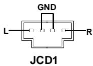
CD-In Connector: JCD1
This connector is provided for external audio input.
13 1 JTPM1
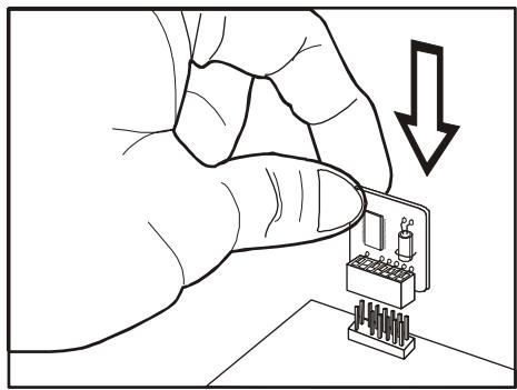
TPM Module connector: JTPM1
This connector connects to a TPM (Trusted Platform Module) module. Please refer to the TPM security platform manual for more details and usages.
| Pin | Signal | Description | Pin | Signal | Description |
| 1 | CLK | LPClock | 2 | 3Vdual/3V_STB | 3V dual or 3V standby power |
| 3 | LRST# | LPCreset | 4 | VCC3 | 3.3V power |
| 5 | LAD0 | LPC address & data pin0 | 6 | SIRQ | Serial IRQ |
| 7 | LAD1 | LPC address & data pin1 | 8 | VCC5 | 5Vpower |
| 9 | LAD2 | LPC address & data pin2 | 10 | KEY | No pin |
| 11 | LAD3 | LPC address & data pin3 | 12 | GND | Ground |
| 13 | LFRAME# | LPCFrame | 14 | GND | Ground |
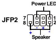
Front Panel Connectors: JFP1/JFP2
These connectors are for electrical connection to the front panel switches and LEDs. The JFP1 is compliant with Intel® Front Panel I/O Connectivity Design Guide.
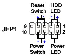
JFP1 Pin Definition
| PIN | SIGNAL | DESCRIPTION |
| 1 | HD_LED + | Hard disk LED pull-up |
| 2 | FP PWR/SLP | MSG LED pull-up |
| 3 | HD_LED - | Hard disk active LED |
| 4 | FP PWR/SLP | MSG LED pull-up |
| 5 | RST_SW - | Reset Switch low reference pull-down to GND |
| 6 | PWR_SW- | Power Switch high reference pull-down to GND |
| 7 | RST_SW + | Reset Switch high reference pull-up |
| 8 | PWR_SW+ | Power Switch low reference pull-up |
| 9 | RSVD_DNU | Reserved. Do not use. |
JFP2 Pin Definition
| PIN | SIGNAL | DESCRIPTION |
| 1 | GND | Ground |
| 2 | SPK- | Speaker- |
| 3 | SLED | SuspendLED |
| 4 | BUZ+ | Buzzer+ |
| 5 | PLED | PowerLED |
| 6 | BUZ- | Buzzer- |
| 7 | NC | Noconnection |
| 8 | SPK+ | Speaker+ |
Front Panel Audio Connector: JAUD1
This connector allows you to connect the front panel audio and is compliant with Intel® Front Panel I/O Connectivity Design Guide.

HD Audio Pin Definition
| PIN | SIGNAL | DESCRIPTION |
| 1 | MIC_L | Microphone - Left channel |
| 2 | GND | Ground |
| 3 | MIC_R | Microphone - Right channel |
| 4 | PRESENCE# | Active low signal-signals BIOS that a High Definition Audio dongle is connected to the analog header. PRESENCE# = 0 when a High Definition Audio dongle is connected |
| 5 | LINE out_R | Analog Port - Right channel |
| 6 | MIC_JD | Jack detection return from front panel microphone JACK1 |
| 7 | Front_JD | Jack detection sense line from the High Definition Audio CODEC jack detection resistor network |
| 8 | NC | No control |
| 9 | LINE out_L | Analog Port - Left channel |
| 10 | LINEout_JD | Jack detection return from front panel JACK2 |
AC'97 Audio Pin Definition
| PIN | SIGNAL | DESCRIPTION |
| 1 | MIC | Microphone input signal |
| 2 | GND | Ground |
| 3 | MIC_PWR | Microphonepower |
| 4 | NC | No Control |
| 5 | LINE out_R | Right channel audio signal to front panel |
| 6 | NC | No Control |
| 7 | NC | No Control |
| 8 | Key | No pin |
| 9 | LINE out_L | Left channel audio signal to front panel |
| 10 | NC | No Control |
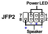
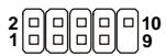
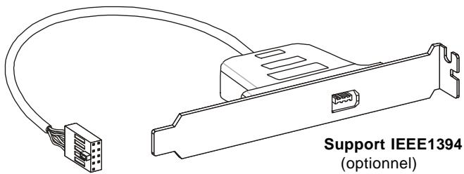
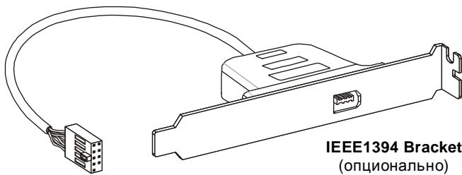
IEEE1394 Connector: J1394_1 (Optional)
This connector allows you to connect the IEEE1394 device via an optional IEEE1394 bracket.
2 10 9
J1394_1
Pin Definition
| PIN | SIGNAL | PIN | SIGNAL |
| 1 | TPA+ | 2 | TPA- |
| 3 | Ground | 4 | Ground |
| 5 | TPB+ | 6 | TPB- |
| 7 | Cable power | 8 | Cable power |
| 9 | Key (no pin) | 10 | Ground |
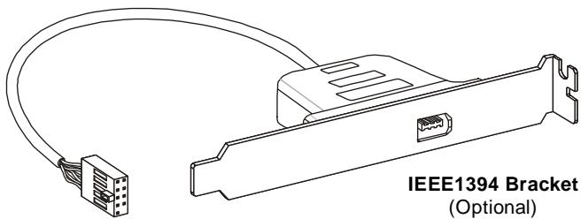
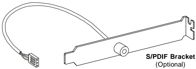
S/PDIF-Out Connector: JSP1
This connector is used to connect S/PDIF (Sony & Philips Digital Interconnect Format) interface for digital audio transmission.
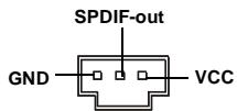
JSP1
Front USB Connector: JUSB1/ JUSB2
This connector, compliant with Intel® I/O Connectivity Design Guide, is ideal for connecting high-speed USB interface peripherals such as USB HDD, digital cameras, MP3 players, printers, modems and the like.
JUSB1 JUSB2
Pin Definition
| PIN | SIGNAL | PIN | SIGNAL |
| 1 | VCC | 2 | VCC |
| 3 | USB0- | 4 | USB1- |
| 5 | USB0+ | 6 | USB1+ |
| 7 | GND | 8 | GND |
| 9 | Key(no pin) | 10 | USBOC |
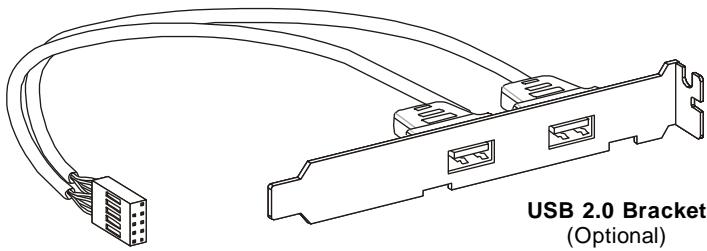

Important
Note that the pins of VCC and GND must be connected correctly to avoid possible damage.
Jumpers
Clear CMOS Jumper: JBAT1
There is a CMOS RAM onboard that has a power supply from an external battery to keep the data of system configuration. With the CMOS RAM, the system can automatically boot OS every time it is turned on. If you want to clear the system configuration, set the jumper to clear data.

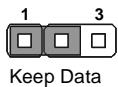
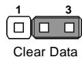

Important
You can clear CMOS by shorting 2-3 pin while the system is off. Then return to 1-2 pin position. Avoid clearing the CMOS while the system is on; it will damage the mainboard.
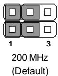
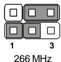
Hardware Overclock FSB Jumpers: JFSB1/ JFSB2
You can overclock the FSB to increase the processor frequency by changing the jumpers JFSB1 and JFSB2. Follow the instructions below to set the FSB.
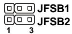
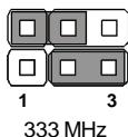

Important
- Make sure that you power off the system before changing the jumpers.
- Please default OC jumper if you need to support FSB400 CPU.
Slots
PCI (Peripheral Component Interconnect) Express Slot
The PCI Express slot supports the PCI Express interface expansion card.
The PCI Express x 16 supports up to 4.0 GB/s transfer rate.
The PCI Express x 1 supports up to 250 MB/s transfer rate.
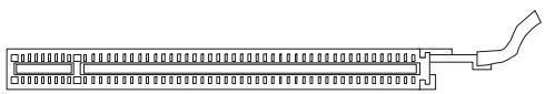
PCI Express x16 Slot
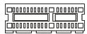
PCI Express x1 Slot
PCI (Peripheral Component Interconnect) Slot
The PCI slot supports LAN card, SCSI card, USB card, and other add-on cards that comply with PCI specifications.
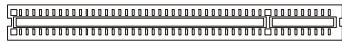
32-bit PCI Slot

Important
When adding or removing expansion cards, make sure that you unplug the power supply first. Meanwhile, read the documentation for the expansion card to configure any necessary hardware or software settings for the expansion card, such as jumpers, switches or BIOS configuration.
PCI Interrupt Request Routing
The IRQ, acronym of interrupt request line and pronounced I-R-Q, are hardware lines over which devices can send interrupt signals to the microprocessor. The PCI IRQ pins are typically connected to the PCI bus pins as follows:
| Order 1 | Order 2 | Order 3 | Order 4 | |
| PCI Slot 1 | INTA# | INT B# | INT C# | INTD# |
| PCI Slot 2 | INT B# | INTC# | INTD# | INTA# |
| PCI Slot 3 | INTC# | INT D# | INTA# | INTB# |
BIOS Setup
This chapter provides basic information on the BIOS Setup program and allows you to configure the system for optimum use. You may need to run the Setup program when:
- An error message appears on the screen during the system booting up, and requests you to run BIOS SETUP.
- You want to change the default settings for customized features.

Important
- The items under each BIOS category described in this chapter are under continuous update for better system performance. Therefore, the description may be slightly different from the latest BIOS and should be held for reference only.
- Upon boot-up, the 1st line appearing after the memory count is the BIOS version. It is usually in the format:
A7392IMS V2.0 071307 where:
1st digit refers to BIOS maker as A = AMI , W = AWARD , and P = PHOENIX .
2nd - 5th digit refers to the model number.
6th digit refers to the chipset as I = Intel, N = n Vidia, and V = VIA .
7th - 8th digit refers to the customer as MS = all standard customers.
V2.0 refers to the BIOS version.
071307 refers to the date this BIOS was released.
Entering Setup
Power on the computer and the system will start POST (Power On Self Test) process. When the message below appears on the screen, press key to enter Setup.
Press DEL to enter SETUP
If the message disappears before you respond and you still wish to enter Setup, restart the system by turning it OFF and On or pressing the RESET button. You may also restart the system by simultaneously pressing
Getting Help
After entering the Setup menu, the first menu you will see is the Main Menu.
Main Menu
The main menu lists the setup functions you can make changes to. You can use the arrow keys (↑↓) to select the item. The on-line description of the highlighted setup function is displayed at the bottom of the screen.
Sub-Menu
If you find a right pointer symbol (as shown in the right view) appears to the left of certain fields that means a sub-menu containing additional options can be launched from this field. You can use control keys ( ) to highlight the field and press
SATA1
SATA2
SATA3
SATA4
control keys to enter values and move from field to field within a sub-menu. If you want to return to the main menu, just press
General Help
The BIOS setup program provides a General Help screen. You can call up this screen from any menu by simply pressing
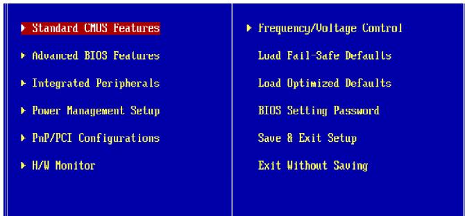
The Main Menu
Once you enter AMI® or AWARD® BIOS CMOS Setup Utility, the Main Menu will appear on the screen. The Main Menu allows you to select from ten setup functions and two exit choices. Use arrow keys to select among the items and press
Standard CMUS Features
Advanced BIOS Features
Integrated Peripherals
Power Management Setup
PnP/PCI Configurations
H/W Monitor
Frequency/Voltage Control
Load Fail-Safe Defaults
Load Optimized Defaults
BIOS Setting Password
Save 8 Exit Setup
Exit Without Saving
Standard CMOS Features
Use this menu for basic system configurations, such as time, date etc.
Advanced BIOS Features
Use this menu to setup the items of AMI® special enhanced features.
Integrated Peripherals
Use this menu to specify your settings for integrated peripherals.
Power Management Setup
Use this menu to specify your settings for power management.
PnP/PCI Configurations
This entry appears if your system supports PnP/PCI.
H/W Monitor
This entry shows your PC health status.
Frequency/Voltage Control
Use this menu to specify your settings for frequency/voltage control and overclocking.
Load Fail-Safe Defaults
Use this menu to load the default values set by the BIOS vendor for stable system performance.
Load Optimized Defaults
Use this menu to load the default values set by the mainboard manufacturer specifically for optimal performance of the mainboard.
BIOS Setting Password
Use this menu to set the password for BIOS.
Save & Exit Setup
Save changes to CMOS and exit setup.
Exit Without Saving
Abandon all changes and exit setup.
When enter the BIOS Setup utility, follow the processes below for general use.
- Load Optimized Defaults : Use control keys ( ↑ ↓ ) to highlight the Load Optimized Defaults field and press
, a message as below appears:
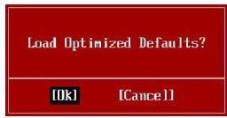
Select [Ok] and press Enter to load the default settings for optimal system performance.
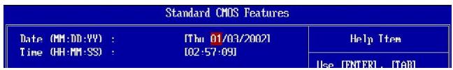
- Setup Date/ Time : Select the Standard CMOS Features and press
to enter the Standard CMOS Features-menu. Adjust the Date, Time fields.
- Save & Exit Setup: Use control keys (↑↓) to highlight the Save & Exit Setup field and press
, a message as below appears:
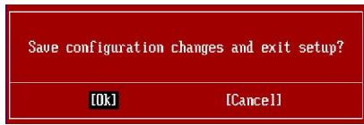
Select [Ok] and press Enter to save the configurations and exit BIOS Setup utility.

Important
The configuration above are for general use only. If you need the detailed settings of BIOS, please see the manual in English version on MSI website.
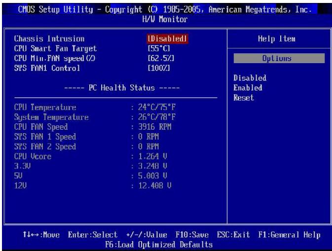
4. H/W Monitor Introduction
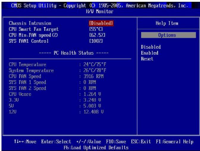
Chassis Intrusion
The field enables or disables the feature of recording the chassis intrusion status and issuing a warning message if the chassis is once opened. To clear the warning message, set the field to [Reset]. The setting of the field will automatically return to [Enabled] later.
CPU Smart FAN Target
The mainboard provides the Smart Fan function which can control the CPU fan speed automatically depending on the current temperature to keep it with in a specific range. You can select a fan target value here. If the current CPU fan temperature reaches to the target value, the smart fan function will be activated. It provides several sections to speed up for cooling down automatically.
CPU Min.FAN Speed (%)
This field is used to set the minimum CPU fan speed.
SYS FAN1 Control
The field allows you to determine whether the system fan connected to SYSFAN1 will work or not when the system is turned on.
PC Health Status
CPU/ System Temperature, CPU FAN/ SYS FAN1/ 2 Speed, CPU Vcore, 3.3V, 5V, 12V
These items display the current status of all of the monitored hardware devices/ components such as CPU voltage, temperatures and all fans' speeds.
Software Information
Take out the Driver/Utility CD that is included in the mainboard package, and place it into the CD-ROM drive. The installation will auto-run, simply click the driver or utility and follow the pop-up screen to complete the installation. The Driver/Utility CD contains the:
Driver menu - The Driver menu shows the available drivers. Install the driver by your desire and to activate the device.
Utility menu - The Utility menu shows the software applications that the mainboard supports.
WebSite menu- The WebSite menu shows the necessary websites.

Important
Please visit the MSI website to get the latest drivers and BIOS for better system performance.
FSB (Front-Side-Bus)
- 1333/ 1066/ 800 MHz
Chipsatz
- North-Bridge: Intel® P31/ G31 Chipsatz
- South-Bridge: Intel® ICH7R/ICH7 Chipsatz
Speicher
- DDR2 800/667 SDRAM (max. 4GB)
- 4 DDR2 DIMMs (240Pin/1.8V)
CPU (Central Processing Unit)
These audio connectors are used for audio devices. You can differentiate the color of the audio jacks for different audio sound effects.
■ Line-In (Blue) - Line In, is used for external CD player, tapeplayer or other audio devices.
Line-Out (Green) - Line Out, is a connector for speakers or headphones.
■ Mic (Pink) - Mic, is a connector for microphones.
■ RS-Out (Black) - Rear-Surround Out in 4/5.1/7.1 channel mode.
CS-Out (Orange) - Center/ Subwoofer Out in 5.1/7.1 channel mode.
SS-Out (Gray) - Side-Surround Out 7.1 channel mode.
Anschlüsse
| POL | SIGNAL | BESCHREIBUNG |
| 1 | MIC | Microphone input signal |
| 2 | GND | Ground |
| 3 | MIC_PWR | Microphonepower |
| 4 | NC | No Control |
| 5 | LINE out_R | Right channel audio signal to front panel |
| 6 | NC | No Control |
| 7 | NC | No Control |
| 8 | Key | No pin |
| 9 | LINE out_L | Left channel audio signal to front panel |
| 10 | NC | No Control |
IEEE1394-Socket: J1394_1 (Optional)
| POL | SIGNAL | POL | SIGNAL |
| 1 | TPA+ | 2 | TPA- |
| 3 | Ground | 4 | Ground |
| 5 | TPB+ | 6 | TPB- |
| 7 | Cable power | 8 | Cable power |
| 9 | Key(no pin) | 10 | Ground |

S/PDIF-Ausgang:JSP1
PCI (Peripheral Component Interconnect) Express Slot
PCI (Peripheral Component Interconnect) Slot
Press DEL to enter SETUP
Advanced BIOS Features
Integrated Peripherals
Power Management Setup
PnP/PCIFeatures
H/W Monitor
Frequency/Voltage Control
Load Fail-Safe Defaults
Load Optimized Defaults
BIOS Setting Password
Save & Exit Setup
Exit Without Saving
Standard CMOS Features
Advanced BIOS Features
Integrated Peripherals
Frequency/Voltage Control
BIOS Setting Password
CPU Smart FAN Target
(SS: single side (une face), DS: double side(doubles face), X: mémoire non installée)
| PIN | SIGNAL | DESCRIPTION |
| 1 | HD_LED + | Hard disk LED pull-up |
| 2 | FP PWR/SLP | MSG LED pull-up |
| 3 | HD_LED - | Hard disk active LED |
| 4 | FP PWR/SLP | MSG LED pull-up |
| 5 | RST_SW - | Reset Switch low reference pull-down to GND |
| 6 | PWR_SW- | Power Switch high reference pull-down to GND |
| 7 | RST_SW + | Reset Switch high reference pull-up |
| 8 | PWR_SW+ | Power Switch low reference pull-up |
| 9 | RSVD_DNU | Reserved. Do not use. |
| PIN | SIGNAL | DESCRIPTION |
| 1 | GND | Ground |
| 2 | SPK- | Speaker- |
| 3 | SLED | SuspendLED |
| 4 | BUZ+ | Buzzer+ |
| 5 | PLED | PowerLED |
| 6 | BUZ- | Buzzer- |
| 7 | NC | Noconnection |
| 8 | SPK+ | Speaker+ |
| PIN | SIGNAL | DESCRIPTION |
| 1 | MIC_L | Microphone - Left channel |
| 2 | GND | Ground |
| 3 | MIC_R | Microphone - Right channel |
| 4 | PRESENCE# | Active low signal-signals BIOS that a High Definition Audio dongle is connected to the analog header. PRESENCE# = 0 when a High Definition Audio dongle is connected |
| 5 | LINE out_R | Analog Port - Right channel |
| 6 | MIC_JD | Jack detection return from front panel microphone JACK1 |
| 7 | Front_JD | Jack detection sense line from the High Definition Audio CODEC jack detection resistor network |
| 8 | NC | No control |
| 9 | LINE out_L | Analog Port - Left channel |
| 10 | LINEout_JD | Jack detection return from front panel JACK2 |
| PIN | SIGNAL | DESCRIPTION |
| 1 | MIC | Microphone input signal |
| 2 | GND | Ground |
| 3 | MIC_PWR | Microphonepower |
| 4 | NC | No Control |
| 5 | LINE out_R | Right channel audio signal to front panel |
| 6 | NC | No Control |
| 7 | NC | No Control |
| 8 | Key | No pin |
| 9 | LINE out_L | Left channel audio signal to front panel |
| 10 | NC | No Control |
| PIN | SIGNAL | PIN | SIGNAL |
| 1 | TPA+ | 2 | TPA- |
| 3 | Ground | 4 | Ground |
| 5 | TPB+ | 6 | TPB- |
| 7 | Cable power | 8 | Cable power |
| 9 | Key (no pin) | 10 | Ground |
Slot PCI (Peripheral Component Interconnect) Express
Slot PCI (Peripheral Component Interconnect)
| Order 1 | Order 2 | Order 3 | Order 4 | |
| PCI Slot 1 | INTA# | INT B# | INT C# | INTD# |
| PCI Slot 2 | INT B# | INT C# | INTD# | INTA# |
| PCI Slot 3 | INT C# | INT D# | INTA# | INTB# |
Réglages BIOS
Advanced BIOS Features
Integrated Peripherals
Power Management Setup
PnP/PCI Configurations
H/W Monitor
Frequency/Voltage Control
Load Fail-Safe Defaults
Load Optimized Defaults
BIOS Setting Password
Save 8 Exit Setup
Exit Without Saving
Standard CMOS Features (Fonctions CMOS standard)
PnP/PCI Configurations (Configurations PnP/PCI)
CPU Smart FAN Target
-1Фnnonnp
-Подержka 1 FDD c 360KB,720KB,1.2MB,1.44MB u 2.88MB
KOHHeKTopbl
3aandne nanei
-1PS/2 npotMbIu
-1PS/2npTKJIaBnAtypbl
-1napaannenbHnI npT
-1 nocneIOBaTeIbHbI npT
-1 pa3bem LAN
- 4 nopTa USB
-63BykoBbIX pa3beMOB
Pa3bembl, yctahOBHeHHbIe Ha nIaTe
-2pa3bemaUSB
- 1 pa3bem CD-in
- 1 pa3bem S/PDIF-out
- 1 pa3bem Дя подклю悔ну aydno Ha nepeДи паHeN
-1pa3bem DaTcNka OTKpbBaHnK Kopnyca
-1pa3bem 1394 (onuohnohno)
-1pa3bemJTPMMoDyIa
Cnotbl
- 1 cnot PCI Express x16
-2 cnoTa PCI Express x1
-3 cnoTa PCI (nOДeprжka nHTeppeIca PCI uINHbI c nITaHneM 3. 3V/5V)
ΦopM ΦakTop
-ATX(30.5cm×23.6cm)
Kpenenne
-6OTBepctnIДЯKpePJIeHNA
PykoBoDCTBO no pa3MeUeHnIO KOMNoHeTOB
CPU (ZeHTpaJIbHbI npoceccop)
Ipn yctaHOBKe CPU, yTO6bI y6epey npoceccop ot neperpeBa, y6eHNTecb B TOM, yTO npoeeccopnI KUnep ycTaHOBJIeN. EcIIy y Bac HET npoeeccopHOrO KUepa, noXaIyIcTa, CBXHTecB C DInpePOM C cJeIbIO npno6peTHeN I er O yCTaHOBKn Do TOrO, KAK BKNoHTe KOMNbHTep. Camyo nocdeHIO unfoopMaIIO o CPU moXHo nOnyuum Ha caun http://global.msi.com.tw/index.php?func=cpuform

BHHMaHHe
Ipepeee
Ipeapee mojem cepbe3no noepedumb uehmpanbHbI npoucecop u cuscmemy. 4mo6bl ybepey npoucecop om nepeapeea, ybebumecb e mom, ymo npouceccopbI kynep paobaem HopmaIbHO. 4mo6bl yeenuuumb meennopacceueaue, ybebumecb e mom, ymo hanecen cnoi meennonpoobrae naembI (unmennnonpoobraeJeHmbI) Mekjdy npoucecopoU padamopom.
3aMeHa CPU
Ipu 3aeme CPU, eo u36exaHue e2o noepexdeHua, o63ameNbHO omKnluome UcmoHuk numaHua unu bblme bukky bnoka numaHua u3 po3emku.
Pa320H
3ma cuscmemna nnama noddepkuaem "pa3a0n". Ondako, y6edumecb, ymo kOmnoHeHmbi cuscmbi cnocobnb pa6omamb e maux hecmndapmhbix pexumax npu pa3a0he. He pekomehdyemc ucnolb3oebam npodykm e pexumax, He coombemcmeyoux yka3aHHbM e cneuzufkauaux. Mbl he zapaanmuyem 3auumy om noepjdehu u puckoe, bI3eAHbIX HnpeunbHOJ 3Kcnnyamaueu u ycmanoeko napamempoe c npebiweh em xapakmepucmuk.
BVeHEny yctaHOBKn npoceccopa LGA 775
BnI npoceccopa co cToOpnoBIOKTaKTHoI NaHEn LGA 775.

BHeuHn BnI npOceccopa.
YTo6bl yBeInuHTb
TeNlOpaccenBaHne, yBeInTecb B
Tom, yTo HaHecen CToi
TeNlONpOBoJaSei NaCTbl.
YcTaHOBka npoceccopa n BENTnIaTopa
Bo n36exahne neperpeba npa6ote o6ra3atbno yctahobnte BeHTnlaTOp npouecoppa. OndOBpemehno, YTObIyBEJIuHtB TeNlopaccenBaHne, y6eJIteCb B TOM, yTO hanecen CToI TEPONPOBOJAEI NaCTbI Ha npoucecope npn yCTAHOBKe BeHTnlaTopa. CLeDyIte HIXKcEJeUOIm Uka3aHnM dI pyapBInbHOY cTAHOBKn. HenpaBnblhaj ycTaHOBKa npBBeTe nobpeXdHn npouceoppa & cIcTeMHOn pIaTbI.
- Pa3bem npoceccopa 3akpbl TnlaactNKOB0 KpbIshKo, KOtopa 3aunuaeT KOHTaKtbp a3bema ot nobpejdeHn. PnOTCyTcBn npocecoppa, Heo6xOdmo Bcerda 3akpblBaTb pa3bem nlaCTNKOB0 KpbIshKo DnA 3aunltb erO KOHTaKTOB.
CHIMITE KpbIshky, NOdHb ee c OJHOI CTOpObl (KaK NOKa3bIBaET CTpeNka).
- OtkpoHOTcKoHTaKTbI pa3beMa.
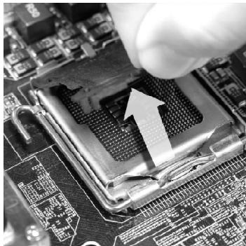
- Notarynte 3a pbiyar kpenneHna.


BHHMaHHe
- Пелег влочецьем сухимьубдumecь, уmo веншалмор павиьно усmahoelen.
- Bo 366exaHue noepkdoHn He npukacuimecb K KOHMkam cokema npouecoppa.
- Haniyue HuxhHei 3aazumHou KpbiuKo Ipnouecoppa 3abucum om Kompnekma nocmaeku.
5.ПоднIMITEpbIyarиOTKpoIteMeTaNIIueCKyO KpbIuKyДЯУctahOBKnIpoUeCCopa.
- Bn3yaIbHo npoBepbTe npaBnIbHocTb yCTaHObKn npoceccopa Bpa3bem. Ecnn npoecccop yCTaHOblen HennpaBnIbHo, To BblHbTe npoecccop npeyectaHObnte.
- Y6eIbWbcB npabnlbHoi opnentauu npoecoppa, noJoxnte npocccop B pa3beM. O6paTnte BnHaHne, yTO BbIeMn Ha npocceope doJXhbl COOTBeTCTBOBaTb BbICTynpam Ha npoccecoPHom pa3beMe.
- Onyctnte MaTaJIInueckyU KpbIshky MexAHn3Ma KpenJeHnA.
9.AkkypatHo onyctnte pblar Ha KpbIky MexaHn3Ma KpeJIeHnna 3aФнкspnyTe erO.ДЯ PhKcaunn pbUcra B MexaHn3Me KpeJIeHnna npeducmOTpe H CneuaJIbHbI BbICTyn.
11.Haxmnte Ha yetbipe 3auekenn m 3akpenite BeHTnIaTOp. 3atem NOBepHnte fNKcatopbl 3aueNOK (Ha npablenne NobopoTa yka3aHO Ha BeHTnIaTope) n 3akpenite nx.

BHMaHne
1.Информацю ob усmaнолелим поцесcope смомрUME e BIOS (e eanaee 3).
2. Ecnu npoueccop He ycmahoene, 3ceda 3akpbiaume pa3bem npanmukoou Kpbikou dny npedomepaueHua nonomok u nonadahue e Hezo apra3u u nbiu. (cmompume yka3aHue 1).
3. Fomo cuscemHou nIambl, pa3meuHHe b 3moU yacMu, npueeDehbl molbKO dner demOncmpaUu ycmaHOeHmuaMopA. Obu uB cuscemHou nIambl 3aeucum om modenu, KynneHHou eAmu.
- CoBmecntte OTBepCTnCnCTEmHOI PnAToBc 3aueKamM KpePnEHHa BEHTnIaTOpa. PnIXMMte padNaTOp C BeHTnIaTOpOM K npOeCCopy INpocJeNTe, YTObIy YeTbIpe 3aueJIKN BOJIN B OTBepCTnCnCTEmHOI PnAToB.
12.ПepeBepHnTe CnCTeMHyO nIaTy u ybeDntecb, yTO 3aUeKn H aE xHo y d e pXnBaIoT BeHTnJIaTOp.
PamrTb
CnoTb DIMM nCnOlb3yIOTc IaI yCTaHOBKn MoJyIe NaMaTn.
(3a Долоннтелов Иформаши O COBMECTUMbIX KOMПОHEHTax NO CEТITE caNT http://global.msi.com.tw/index.php?func=testreport)
DDR2 240-pin,1.8V

Single-Channel: All DIMMs in GREEN
Dual-Channel: Channel A in GREEN; Channel B in ORANGE
I3-3a orpaHnueHn Ynceta, Ira pa6OtbB DByXkHaJIbHOM nIN OndHOKaHaJIbHOM pexKMe Heo6xOdmo NcNoJb3OBaTb MoyJIn PamrT B COOTBeTCTBUN CcIeMyuSei TabIuSei.
Bo3MoXHbIe coUeTaHnMaDyNei naMrtu
(OC: odnoctopohnn, DC: dBvctopohnn, X: he yctahOBJIeH)
YcTaHOBka MoDyJeN nAmrTn
- Modynl namrtn mmeot toIbko Ondy npope3b B cepeHne. MoDyIb BoIeT B pa3bem ToIbko npn npaBnIbHOJ opneHTaun.
- BCTabTe MoyIb B DIMM cIOT B BepTikakbHOM HnpaBHeHH. 3aTe m Haxmnte Ha Hero, yTo6bl 30NoeHbe KOHTAKtbl rIy6oKo NOrpy3uNIncB B DIMM cIOT. Ecnn MoyIb PAmrtn BCTabHEn PpaBnJbHo, To PnaCTIKOBbE 3aueJkn Ha obox KOHcX 3akpoOTc ABTomatUcheKn.

BHHMaHHe
3oIombIe KOHmKmbI eBa BuHbI, ecu MoyIu nammu npaunbHo pa3MeueHbE DIMM cnome.
- BpyHyu y6eHITecb, yTO MOyIb 3aKpeIJIeN B CnOte DIMM 3aUeIeKamn C o6eHX CTOpOH.

BHMaHne
- Modynu DDR2 He ε3aumozamenebMc modyjmu DDR, u cmahandpM DDR2 He umeem obpamnoi coemecmumocmu. Cneydem ycmahanabnabMb modyu nammu DDR2 e pa3bembl DDR2 DIMM.
-Дя pa6obombe 8 deyxaKaHbHom pexume y6edumecb,уmo e pa3bEmax pa3hbx KaHaNoE y 8ac ycmaHoBJIbHbMoDyno odHOo muna u oduHaKOBou EMKocMu. - 4mo6bI cucmema 3a2py3unacb, eHaayane ycmaHOeume moyu pa3bEM DIMM1.
- 13-3a cneuufku pacnpedenehura cuscemhbx pecypco8 yuncema, objemdocmynho nammu moxem makcumalbno cocmaumb 3+ΓB (Ho He 4ΓB) npu ycmanoeke modyneu nammu 1ΓB e kaxdbu u3 cnomoe.
Pa3bem nHTaHn
24-KoHTaKTHbI pa3bEm nHTaHnA TX:ATX1
3TOT pa3bem n03BOJnEeT NOkKJIouHtB 24-KoHTaKTThbI NITaHnA ATX.ДЯ NOkKlUoyEnHaNCTOuHnKa y6eDInTeCb, YTO erO pa3bem IN KOHTaKbI npaBnJIbHO copneHTnpOBaHbI. 3aTeM IIOTHO BCTaBbTe erO B pa3bem Ha CnCTeMHo PnATE.
Bb taKxe moKete nCnoJb3ObaTb 20-koHTaKTbHb ATX 6nok nHTAHn. Pp n CnoJb3ObaHnN 20-koHTaKTHoro pa3beMa, NOdKJIouaHte erO BdoJb KOHTaKTOB 1 n 13 (cmOpnte n3o6paXeHne HApPaba). B cToPOHe KOHTaKTOB 11, 12, 23 & 24 OcOBeHHb 3HaK dJa I36ExaHnH enPaBnIbHOY yCTaHOBKn.
Pin Definition
| PIN | SIGNAL | PIN | SIGNAL |
| 1 | +3.3V | 13 | +3.3V |
| 2 | +3.3V | 14 | -12V |
| 3 | GND | 15 | GND |
| 4 | +5V | 16 | PS-ON# |
| 5 | GND | 17 | GND |
| 6 | +5V | 18 | GND |
| 7 | GND | 19 | GND |
| 8 | PWROK | 20 | Res |
| 9 | 5VSB | 21 | +5V |
| 10 | +12V | 22 | +5V |
| 11 | +12V | 23 | +5V |
| 12 | +3.3V | 24 | GND |
Pa3bem nItaHnA BX 12V:JPW1
3TOT pa3bem nHTAHn 12V JPW1 nCnoJb3yETc dIg oBecneueHn nHTAHn npoueCCopa.
Pin Definition
| PIN | SIGNAL |
| 1 | GND |
| 2 | GND |
| 3 | 12V |
| 4 | 12V |

BHMaHne
- Y6eumecb e mom, ymo ece pa3bembl nokkIouhenb K ucmouHukam numanur ATX dner cma6unbhou pa6ombl cucmemHo nnambl.
2.Дясma6unbHocmu cucmembi HacmoernbHo pekomehoyemca uonb30eamb ucmouhuk numaHua Ha 350 Bm (u eblue).
3aHnaHaHeJIb
Pa3bemblmbiwn/KnaBnataypbl
CtaHapThbIe pa3beMbI DIN PS/2® dЯ noДКЛЮЧЕня Мblи/NKlaBnAtypblc INTepeM COM PS/2®.
Pa3bemnapaJIeJIbHoro npota
IpaJIeJIbHbI npOT - 3TO cTaHdApTbI npOT dJa npInTepa. OH nOJdePJIuBaET peKIMbEPP (ycOBepWeHcTBoBAHHbI npaJIeJIbHbI npOT) n ECP (napJIeJIbHbI npOT c DOJONHHTeJIbHbIM BO3MOXHOCTaM).
Pa3bem nocJeDoBaTeIbHoro npota
3To BbICOKoKOpocTHo NocJeDoBaTeBHyn nopT CBy3N 16 A c 16-6HTHO nepeDauey FIFO.K 3ToMy pa3bemy MoKHo HEnocPeDCTBeHNO nOdkNoHTbMbIb dJa NocJeDoBaTeBHorO npTa nn Dpyroe yctpoiCTBO.
> NopT USB
Iopr USB (Universal Serial Bus) no3B0nraT noDknOuTaB TaKne USB ycTpoiCTBa, KAK KnaBnATypa, Mblb N T.D.
Pa3beM LAN
CtanhTbI pa3bem RJ-45 IJI NaKJIIOUeHn K JOKaJIbHO BByNCInTeJbHO CETN (LAN). K Hemy NpokJIIOUaEcTc Ka6eJIb JOKaJIbHO CETN.

| LED | LbeT | Ní míñj kčá LED | Описане |
| Лев. | Жěлт. | HeT | LAN coeşнене He yctanobného. |
| EcTB (noctoHnO) | LAN coeşнене yctanobného. | ||
| EcTB (ячe & mirae?) | Сяозь с дугим komльютөрм no LAN. | ||
| Пав. | Зелен. | HeT | Сkopocstb пераши 10 M6/c. |
| EcTB | Сkopocstb пераши 100 M6/c. | ||
| Оразк. | EcTB | Сkopocstb пertaши 1000 M6/c. |
Ayno pa3bembl
3Tn pa3bembl nCnoJb3yIOCTdIJI NOKJIQUeHn 3ByKObIX yCTpoiCTB. Pa3beMbl, BbIIOHRAUJIne pa3HbIe fYHKUN, IMEOT pa3NIuHbIe cBeta.
Bxod aydno (Tony6o) - JInHeHbI BxO, nCNoJIb3yETcJnI npKJIuOeHHa BHeWero CD npOnrPbIBaTeJIa, MarHHTofoHOa IIN dpYnx 3ByKObIX yCTpOICTB.
BbIXoJ aydno (3eIeHbI) -JIHeIHyI BbIXOДЯ NOKlHoyeHnayUHNIKOB UIN KONOHOK.
MnKpoΦoH (Po3OBbI) - Pa3bEm IaI NOkIuYeHn MnkpoΦoHa.
BbIXoRD RS (Yeprh) - BbIXoHa 3aDnHe KOIOHKn BpeKmE 4/5.1/7.1.
BbIXoD CS (OpaXkeBbI) - BbIXoHa ueHTpaJIbHyIO KOJOhKy I ca6Bypep B peKIme 5.1/7.1.
BbIXoD SS (Cepbl) - BbIXoJ Ha 60KOBbIe KOJOnHKn BpeXmE 7.1.
KOHHeKTopbl
Pa3beM FDD:FDD1
Pa3bem noIeepKbAeT FDD eMkoctbIO 360KB, 720KB, 1.2MB, 1.44MB nII 2.88MB.
Pa3bem IDE:IDE1
Pa3bem noDaepeKnaBaet JeCTkM DNCK IDE, DOnOpHnTeIbHoe DnCKOBoe yCTpoiCTBO n dpyrne ycTPOIcTBa c INTEppeiCom IDE.
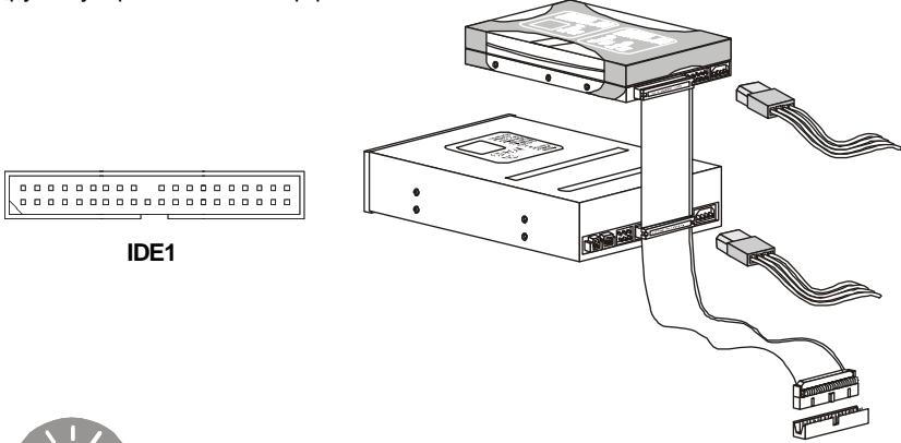

BhimaHne
Ipu nooknueenu dax ycmpoucme ha odHom kahe, cneyem ycmaohumby cmpoucmea e pexum master / slave nocpedcmeom ycmaohku nepembyku. 3a uhcmpkyuuma obpamumeb K dokymehmauu uzomoumeny cmpoucmea.
Pa3bem Serial ATA: SATA1/ SATA2/ SATA3/ SATA4
Даннь pa3bemЯВлетсу ВICOKOCKOPOCTHbIM NOPTomИHTeppeca Serial ATA. JIIO60 pa3bem Serial ATA moKet coeINHrTbcr c OONM yCTpoiCTBOM Serial
ATA.
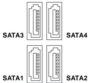

BHMaHne
U36euaime, noxanyucma, pe3kux u3u6o8 ka6enr Serial ATA. B npomueHom cnyuae mozym 03Hukhmyb nomepu daHHbx npu nepedaue.
Pa3bembl nHTaHnB BeHTnJIaTOpOB: CPUFAN1/SYSFAN1/SYSFAN2 / SYSFAN3
Pa3bEmblnTaHnB BeHTnIaTOPOndepKnBaHOBeHTnIaTObpC nITaHnEM+12B. Ppi NpOKIIOUeHHN Heo6xOIMNOOMHNb, YTO KpaCHbI npOBOD nOdkIIOuAeTcK uHHe +12B, UepHbI - K 3emNe GND. EcnHa cncTeMHOn IPiATE yCTaHOBLeHa MKNpOxCema aannapathoro MOHToPunHra, Heo6xOIMNOICNoJIb3OBAbTCneuaJIbHbIe BEHTnIaTObpC dDatHKAMN CKOpOCTn DnpeaIN3aUNfYHKUNynpABLeHHN
BeHTUNIaTOpamN.
CPUFAN1
SYSFAN1 SYSFAN3
SYSFAN2

BhIMaHne
- Ymobbl y3nambb o ModeJnx noDxoduux eHmunrmpoe obpamumecb, nokanyucma, ha oPhiuaIbHbI e6 caum un npokohcyIbmupyumecb c npodabouom.
- Pa3bem CPUFAN noodepxueaem behmunamopby, ka c 3, ma k u c 4 KOhmaekmamu.
- Pa3bem CPUFAN1 noddepkuaeaem fynkuu ynpaenenue ehemunamopom. Bbl moxeme cde lamb heoxbodumbe hacmpouke pa3dene H/W Monitor bBIOS Setup. Bbl maKxe moxeme ycmaHoomb npunoXeHue DualCore Center, komopoe nozolum aemomamuuecku konmpolupoabm ckopocmb epaenuee ehemunamopa CPU 3abucumocmu om memnepamypbl.
Pa3bem daTUnka OTKpbIBaHnK Kopnyca: JCI1
K 3TOMy KOHHeKTopy NIOKnIHyaTeC KabeIb DaTuNka, yCTaHOBLeHHORo B Kopnyce. PnO tKpbIbAHmN KOpnyca erO MexAHm3 M AKTNbN3npyTeC. CnCTema 3anOMnHaet 3TO c6blte n Bbldaet npdeynppexdene Ha 3kpaH. Ppeynpexdene MoKHO OTKlnOHHTB HacTpoKax BIOS.
Pa3beM CD-In: JCD1
3TOT KOHNHeKTop npedHa3NaeH dIg IOKnIHyeHn BHeuHero BXoJa ayDIO.
Pa3bem TPM Moynj:JTPM1
| PIN | SIGNAL | DESCRIPTION |
| 1 | HD_LED + | Hard disk LED pull-up |
| 2 | FP PWR/SLP | MSG LED pull-up |
| 3 | HD_LED - | Hard disk active LED |
| 4 | FP PWR/SLP | MSG LED pull-up |
| 5 | RST_SW - | Reset Switch low reference pull-down to GND |
| 6 | PWR_SW- | Power Switch high reference pull-down to GND |
| 7 | RST_SW + | Reset Switch high reference pull-up |
| 8 | PWR_SW+ | Power Switch low reference pull-up |
| 9 | RSVD_DNU | Reserved. Do not use. |

JFP2 Pin Definition
| PIN | SIGNAL | DESCRIPTION |
| 1 | GND | Ground |
| 2 | SPK- | Speaker- |
| 3 | SLED | SuspendLED |
| 4 | BUZ+ | Buzzer+ |
| 5 | PLED | PowerLED |
| 6 | BUZ- | Buzzer- |
| 7 | NC | Noconnection |
| 8 | SPK+ | Speaker+ |
BbHocHo pa3bem aydno: JAUD1
3TOT KOHHeKTop NO3BOJAreT NOdKJIIOHTb BbIHOCHO pa3bEm ayDnO Ha nepeIeHne naHenn COOTBeCTByeT pyKOBOcCTBy Intel® Front Panel I/O Connectivity Design.

HD Audio Pin Definition
| PIN | SIGNAL | DESCRIPTION |
| 1 | MIC_L | Microphone - Left channel |
| 2 | GND | Ground |
| 3 | MIC_R | Microphone - Right channel |
| 4 | PRESENCE# | Active low signal-signals BIOS that a High Definition Audio dongle is connected to the analog header. PRESENCE# = 0 when a High Definition Audio dongle is connected |
| 5 | LINE out_R | Analog Port - Right channel |
| 6 | MIC_JD | Jack detection return from front panel microphone JACK1 |
| 7 | Front_JD | Jack detection sense line from the High Definition Audio CODEC jack detection resistor network |
| 8 | NC | No control |
| 9 | LINE out_L | Analog Port - Left channel |
| 10 | LINEout_JD | Jack detection return from front panel JACK2 |
AC'97 Audio Pin Definition
| PIN | SIGNAL | DESCRIPTION |
| 1 | MIC | Microphone input signal |
| 2 | GND | Ground |
| 3 | MIC_PWR | Microphonepower |
| 4 | NC | No Control |
| 5 | LINE out_R | Right channel audio signal to front panel |
| 6 | NC | No Control |
| 7 | NC | No Control |
| 8 | Key | No pin |
| 9 | LINE out_L | Left channel audio signal to front panel |
| 10 | NC | No Control |
Pa3bem IEEE1394: J1394_1 (onζηοήλνHo)
3TOT KOHKeTOp No3B0JAreT NODKnUChTb NOpTbI IEEE1394 Ha BbyHOcHoi PJIaHKe IEEE1394..
2 10 9
J1394_1
Pin Definition
| PIN | SIGNAL | PIN | SIGNAL |
| 1 | TPA+ | 2 | TPA- |
| 3 | Ground | 4 | Ground |
| 5 | TPB+ | 6 | TPB- |
| 7 | Cable power | 8 | Cable power |
| 9 | Key (no pin) | 10 | Ground |
S/PDIF-Out Connector: JSP1
CnoT PCI (Peripheral Component Interconnect) Express
PCI Express noДержиьаet Kapы paacширони Иntерфсяca PCI Express.
PCI Express x 16 noДержиьаet ckopocьпегдач Danньixdo4.0ΓБ/c.
PCI Express x 1 noДержиьаet ckopocьпегдач Danньixdo250MB/c.
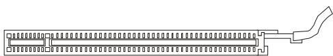
CnotPCIExpressx16
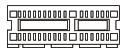
CnotPCIExpressx1
CnotPCI(PeripheralComponentInterconnect)
Cnot PCI no3Bnonr et ycTahOBnTB kapTb LAN, SCSI, USB n dpyne dononHnTeNbHbIe KapTb paSwnpeHn, KOtOpbIe COOTBeTCTByOt Cneunfkaunn PCI.

32-bit cnot PCI

BHMaHne
Ipepe ycmahoekou uu u3eneuehenem Kapm pacwupenru y6edumecb,ymo Kaebn numanur omklnouen om 3nekmpueeckou cemu. Ipoymume DokymehmaucuHa Kapmy pacwupenru u bInonHume Heobxodumble annapamhbue u npnoapamhbie ycmahoeku dner daHHou nnambl, makue kak nepemblyku, nepeknnoamenu uu konphiuaypauuo BIOS.
| Order 1 | Order 2 | Order 3 | Order 4 | |
| PCI Slot 1 | INTA# | INT B# | INT C# | INTD# |
| PCI Slot 2 | INT B# | INT C# | INTD# | INTA# |
| PCI Slot 3 | INT C# | INT D# | INT A# | INT B# |
Hac troponka BIOS
B 3toI rnaBe npuBoaTcO cHOBhIe CBeDeHnO pexmHe HacTpOnKn BIOS (BIOS SETUP), KOTOpbI nO3BOJAEYcTaHOBt ONTMaJIbHyIO KOHfNpyaUHcCTeMbI. 3TO T peKM MoKeT Notpe6oBaTcBcA B CneDyUOxCnyuaX:
- Bo Bpem 3a rpy3kn CnCTeMbI NOBbIeTc8 CoO6uEHe o6 OUn6Ke C Tpe6oBaHneM 3anyctntb BIOS SETUP.
*BbI JeNaete 3aMeHnTb 3aBOdCKne HAcTpOuKn Ha Co6CTBeHHbIe.

BHMaHne
1.Дя улчшеня paobombl cucmembi codepkumoe kaskdo0 u3 pa3deeloe BIOS,paccmampueaemoe e daHou 2naee,nocmoHHo coeepwehcmayemcr.Позмomy,dЯ hoBXx eepcuB BIOS oHO moXem Heckonbko omnuambcr om daHnoO onucaHua, komopoe cmoXem cnjxumb e kauecmbe opuenmupa.
2. Пу заурахь, спегош, пося объема памMu sympeke, сыюдмся обознayенue BIOS. Овicialно соне ушушформam:
A7392IMS V2.0 071307 e:
1a86ka coomeemcmeyem u3aomoeumenIO BIOS (A = AMI, W = AWARD u P = PHOENIX)
Cneyuouue 4 ucpbcoomeemcmeyom Homepy modeu.
Cleedyuzae byka oob3nayem nocmaeuzka yuncema (A = AMD, I = Intel, V = VIA, N = Nvidia, U = ULi).
2 cneodyuue 6kyeobo63naiaom 3aKa3uKa MS = cmahandapmHbI 3aKa3uK.
V2.0 coomeemcmeyem Homepy eepcuu BIOS.
071307 - øama ebinycka BIOS.
Bxod B pexm HactpoKn
BkIIOUHTe nITaHne KOMNbIOTepa. Ipn 3tOM 3aNcyTntc npOceDpya POST (TeCT BKNIOUeHnIITAHn). Korda Ha 3KpaHe NOBNTC npNBedeHHOe Hnke coo6uHHe, HaxMITE KlaBnSy ДЯ BXODa B pexm HacTpoiKn.
Press DEL to enter SETUP
Ecni coo6eHne nCye3no, a BbI He ycpeiHn HaxaTb KnaBnUy, nepe3anyctnte CnCTemy, BblKIIIOuNIB IN CHOBA BKIIIOUHB NITaHne, INI HaxaB KHOJky RESET. MoXHo, TaKKe, nepe3anyctntb CnCTemy, Haxab OndHOBpeMeHHO KnaBnUn
PeknM HacTpoKu
BovBa BpeKIM HacTpoKn, Bbl cpa3y yBnuTe INaBHOe MeHIO.
Main Menu (ΓλαBHOe MeHIO)
Главhoe MeHIO COeepKNT CnICOK HAcTpoE, KOTOpBle Bbl MoXeTe N3MeHHTb.ДЯ BBi6opa MOxH0 NcNoJIb3OBAtB KJIaBnIu Co cTppeNkAmn (↑↓).CnpabKa o
BbIbpaHNo HacTpoNKe OToobpaxKaETcB HnXHeN qactN 3KpaHa.
SATA1
SATA2
SATA3
SATA4
IopmeHIO
Ecni Bbl ObnapyKnte, yTo CnEBA OT nyHKta MeHIO IMeETc3NaK npaboro yka3aTeTn (kak noka3aHO cnpaba) 3TO O3Haay
Hahnue noDMehIO, codepkaeero dononHnteIbHbe HacptpoKn KOtOpble MOXHO Cenatb B 3TOM nyHKTe. NcnoIb3yte ynpabJIOUne KnaBUn (↑↓) nra Bbl6opa a 3aTeM haxMITE
PoiDpo6Na cnpaBka
B pexime hacptpokn BIOS nmeetc B03MOXHOCtB noyuHnnoDpO6HO cnpaBKn. Ee moxho Bbl3BaTb n3 IIObOro MeHIO npocTbIM HaxaTneM
The Main Menu
Пив BXODE bpeKMн HacTpOkn BIOS CMOS ot AMI® nIn AWARD® Ha 3kpae OTObpaKaetcTgIaBHOe MeHIO. TlalBHOe MeHIO nO3BOJnEeB bIbpaTb DecaTb yHKuIM HacTpOkn I mMeET dBa BapnaHTa bIXoJa.ДЯ nepemeUeHn NO nyHKtAm NcNoJIb3yIOTcR KnaBUn Co cTePknAMn
Standard CMOS Features (CTaHdApTbIe fynKcIMn CMOS)
Use this menu for basic system configurations, such as time, date etc.
Integrated Peripherals (BcTpoeHbIe nepupepnHbIe ycTpoCtBa)
3To MeHIO nCnOJIb3yETcAДЯ HAcTpoIKN IapaMeTPOB BCtPoEHHbIX nepuΦePmHbIX yCTpOINCTB.
Power Management Setup (Hactpoika ynpablenen nntaHneM)
3TO MeHIO No3B0JraT 3aDaTb npaMeTpbl ynpaBHeHnI NtTaHmE CnCTeMbI.
PnP/PCI Configurations
3TOT NyHKN NOBnEeTc, ecIn CnCTema noDepKnaeT PnP/PCI.
H/W Monitor (Monitop annapaTHou qactu)
3TOT nyHKT OTObpaKaet COCTOaHne annapaTHou Yactn PIK.
Frequency/Voltage Control
3TOT nyHKT nCnONb3yETcA DnY yCTaHOBKn YactOTbl/HanpJxHn N dpynx HAcTpoek Dnla pa3roHa.
Load Fail-Safe Defaults
3To MeHIO nCnOJIb3yETcIg 3aRpy3Kn 3HaueHnBIOS,yCTaHOBneHHbIX npOn3BOIDTeIeM dIg CTA6uNbHoN CnCTeMbI.
Load Optimized Defaults (YcTaHOBnTb ONTNMaJIbHbIe HAcTPOKn)
3TO MeHIO NcNoIb3yETc DnIy UcTaHOBKn HAcTpoE K3rotOBUnteIaONTHMaJIbHOIpOu3BOIDTeJIbHOCTN CNTeHMo IJaTbl.
BIOS Setting Password (Паров досун Книсторikam BIOS)
3To MeHIO nCnOJb3yETcra, YTO6bl 3aDaTb npoJIb.
Save & Exit Setup (BbIXoD c coxpaHeHem HactpoeK)
3aIncb n3MeHeHn B CMOS n bIxOu n3 peXmHaCTpoKn.
Exit Without Saving (BbIXoJ 6e3 coXpaHEnn)
OTmeHa BCex n3MeHeHn N BbIXoN 13 peXmHa HacTpoKn.
B obuem cnyae, haxoJcB pejHme hactpoKn BIOS, pekomeHdyetcBbIIOHNtB cJeDyUOune DeiCTBna.
BbIbepnTe [Ok] n Haxmnte Enter, TTo6bl coxpaHntb KOHpHpyaunu N BbIeTN u3 BIOS Setup.

BHMaHne
PpueeHnna bIwe konpuaypaun noxdoum dny oseao npumehnua. Ecnu ke aam mpebyomc 6oJee moKue hacpmouku BIOS, opbamuce k anuucokoepcuu pykoedcmea ha e6-caume MSI.
4. H/W Monitor Introduction
Chassis Intrusion
3TOT nyHK T BKNIOUaET INI BbIKIOUaET FyHKUNIO 3aINCS COCTOHN IAATNKA OTKpbIBAHNA KOPNYCA INOKA3a NpeDyPnPEJKeHNA B Cnyae OTKpBITNA KOPNYCA. IpeDyPnPEJKeHNE MOXHO C6pocNTb yCTAHOBKO 3TOTO NYKTA B [Reset]. Notom yCTAHOBKA 3TOTO NyKHTA ABOMATNUeCKN BOCCTAHOBITcB [Enabled].
CPU Smart FAN Target
3ta cnctemhna nnata nmeet yHKcNIO SmartFan, kotopar no3BOJAre KOHTpOInpoBaTb ckopoCTb BpaueHnB eHTnIaTopa CPU B 3aBnCmOcTn OT Tekyuie TeMnepeatypbl, YTO6bl ydepKnbAteB HNeo6xOdmbix npedeJax.
CPU Min.FAN Speed (%)
3TOT NYHK T NcNoIb3yETcA DJIa YCTaHOBKn MInHmAlbHOJ CKOpOCTN BpaUeHnBEHTnIaTOPa IpoUeCCopa.
SYS FAN1 Control
3TOT NyHKT N03BONJET yka3aTB, CJIeNyET JIN BKJIOnuHaTb CNTeMHbI BENTINJrTOp, NOKlnHcHnHk K pa3bemy SYSFAN1.
PC Health Status
CPU/ System Temperature, CPU FAN/ SYS FAN1/2 Speed, CPU Vcore, 3.3V, 5V, 12V
3TN nyHKtbl NOKa3bIbaHOT TeKyuue COCTOHHe BCEx KOMNHOHTOB, KOToPbIE MOHITOpNT CnCTema, TAKNX KAK HAnpJxKeHne CPU, Tempepatpyi nCKopoCTb BCex BEHTNJrTOPOB.
CBeDeHnO npoRpaMMHom o6ecneueHH
YctaHObTe B CD npBOD nck Driver/Utility (JaaiBepbl u ytnnTbl) n3 kOMJIeKta NOCTABKN CNTcEMHNO nlaTb. ABOmatuueckn 3anyCTnTCn HNCTaIIaIyra. IpoCTO haxMITE Ha Na3BaHne dpaBepa/ ytnnTbl n cJeDyte INHCTpykCnMa H a3KpaHe DnA 3aBepeHnna INcTaIaIynn. Nck Driver/Utility coedePknT:
Driver menu (Meho dpaBepOB) - N3 mmeuuxc daPaBepOB bI6peTe HxHbI dJa AKTUBaCm yCTpoiCTBa.
Utility menu (MeHIO yTnJIInT) - CoedepKNT npIKJaNDhIe nporpaMMbl dIy nOdEprKKn CnCTeMHoN pIaTbI.
WebSite menu (Meho Be6caTob) - Copepknt cncok Heo6xOaMbIX Be6caTob.

BHHMaHHe
Ecnu je eam mpebyomc 6oJIe moHKue hacmpouk BuS, obpamumecb K pyko0odcmey Ha ee6-caime MSI.
- Trademarks
- Revision History
- Technical Support
- Notice 1
- Notice 2
- ENGLISH
- DEUTSCH
- Mainboard Specifications
- Processor Support
- Supported FSB
- Chipset
- Memory Support
- LAN
- IEEE 1394 (Optional)
- Audio
- IDE
- SATA
- RAID
- Floppy
- Connectors
- Back panel
- - On-Board Pinheaders
- Slots
- Form Factor
- Mounting
- Quick Components Guide
- CPU (Central Processing Unit)
- Important
- Overheating
- Replacing the CPU
- Overclocking
- Introduction to LGA 775 CPU
- CPU & Cooler Installation
- Memory
- Memory Installation Combination
- Installing Memory Modules
- Power Supply
- ATX 24-Pin Power Connector: ATX1
- ATX 12V Power Connector: JPW1
- Mouse/Keyboard
- Parallel Port
- ▶ Serial Port
- USB Port
- LAN Jack
- Audio Ports
- Floppy Disk Drive Connector: FDD1
- IDE Connector: IDE1
- Serial ATA Connector: SATA1/ SATA2/ SATA3/ SATA4
- Fan Power Connectors: CPUFAN1/ SYSFAN1/ SYSFAN2/ SYSFAN3
- Chassis Intrusion Switch Connector: JCI1
- CD-In Connector: JCD1
- TPM Module connector: JTPM1
- Front Panel Connectors: JFP1/JFP2
- Front Panel Audio Connector: JAUD1
- IEEE1394 Connector: J1394_1 (Optional)
- S/PDIF-Out Connector: JSP1
- Front USB Connector: JUSB1/ JUSB2
- Jumpers
- Clear CMOS Jumper: JBAT1
- Hardware Overclock FSB Jumpers: JFSB1/ JFSB2
- PCI (Peripheral Component Interconnect) Express Slot
- PCI (Peripheral Component Interconnect) Slot
- PCI Interrupt Request Routing
- BIOS Setup
- Entering Setup
- Press DEL to enter SETUP
- Getting Help
- Main Menu
- Sub-Menu
- General Help
- The Main Menu
- Standard CMOS Features
- Advanced BIOS Features
- Integrated Peripherals
- Power Management Setup
- PnP/PCI Configurations
- H/W Monitor
- Frequency/Voltage Control
- Load Fail-Safe Defaults
- Load Optimized Defaults
- BIOS Setting Password
- Save & Exit Setup
- Exit Without Saving
- H/W Monitor Introduction
- Chassis Intrusion
- CPU Smart FAN Target
- CPU Min.FAN Speed (\%)
- SYS FAN1 Control
- PC Health Status
- Software Information
- FSB (Front-Side-Bus)
- Chipsatz
- Speicher
- Anschlüsse
- IEEE1394-Socket: J1394_1 (Optional)
- S/PDIF-Ausgang:JSP1
- Slot PCI (Peripheral Component Interconnect) Express
- Slot PCI (Peripheral Component Interconnect)
- Réglages BIOS
- Standard CMOS Features (Fonctions CMOS standard)
- PnP/PCI Configurations (Configurations PnP/PCI)
- KOHHeKTopbl
- 3aandne nanei
- Pa3bembl, yctahOBHeHHbIe Ha nIaTe
- Cnotbl
- ΦopM ΦakTop
- Kpenenne
- PykoBoDCTBO no pa3MeUeHnIO KOMNoHeTOB
- CPU (ZeHTpaJIbHbI npoceccop)
- BHHMaHHe
- Ipepeee
- 3aMeHa CPU
- Pa320H
- BVeHEny yctaHOBKn npoceccopa LGA 775
- YcTaHOBka npoceccopa n BENTnIaTopa
- BHMaHne
- PamrTb
- YcTaHOBka MoDyJeN nAmrTn
- Pa3bem nHTaHn
- 24-KoHTaKTHbI pa3bEm nHTaHnA TX:ATX1
- Pa3bem nItaHnA BX 12V:JPW1
- 3aHnaHaHeJIb
- Pa3bemblmbiwn/KnaBnataypbl
- Pa3bemnapaJIeJIbHoro npota
- Pa3bem nocJeDoBaTeIbHoro npota
- > NopT USB
- Pa3beM LAN
- Ayno pa3bembl
- Pa3beM FDD:FDD1
- Pa3bem IDE:IDE1
- BhimaHne
- Pa3bem Serial ATA: SATA1/ SATA2/ SATA3/ SATA4
- Pa3bembl nHTaHnB BeHTnJIaTOpOB: CPUFAN1/SYSFAN1/SYSFAN2 / SYSFAN3
- Pa3bem daTUnka OTKpbIBaHnK Kopnyca: JCI1
- Pa3beM CD-In: JCD1
- Pa3bem TPM Moynj:JTPM1
- BbHocHo pa3bem aydno: JAUD1
- Pa3bem IEEE1394: J1394_1 (onζηοήλνHo)
- CnoT PCI (Peripheral Component Interconnect) Express
- CnotPCI(PeripheralComponentInterconnect)
- Hac troponka BIOS
- Bxod B pexm HactpoKn
- PeknM HacTpoKu
- Main Menu (ΓλαBHOe MeHIO)
- IopmeHIO
- PoiDpo6Na cnpaBka
- CBeDeHnO npoRpaMMHom o6ecneueHH
Brand : MSI
Model : G52-73921XK
Category : Laptop