
890FXA-GD70 - Motherboard MSI - Free user manual and instructions
Find the device manual for free 890FXA-GD70 MSI in PDF.

User questions about 890FXA-GD70 MSI
0 question about this device. Answer the ones you know or ask your own.
Ask a new question about this device
Download the instructions for your Motherboard in PDF format for free! Find your manual 890FXA-GD70 - MSI and take your electronic device back in hand. On this page are published all the documents necessary for the use of your device. 890FXA-GD70 by MSI.
USER MANUAL 890FXA-GD70 MSI
The material in this document is the intellectual property of MICRO-STAR INTERNATIONAL. We take every care in the preparation of this document, but no guarantee is given as to the correctness of its contents. Our products are under continual improvement and we reserve the right to make changes without notice.
Trademarks
All trademarks are the properties of their respective owners.
MSI is registered trademark of Micro-Star Int'l Co., Ltd.
NVIDIA® is registered trademark of NVIDIA Corporation.
ATI® is registered trademark of ATI Technologies, Inc.
AMD® is registered trademarks of AMD Corporation.
Intel® is registered trademarks of Intel Corporation.
Windows® is registered trademarks of Microsoft Corporation.
AMl is registered trademark of American Megatrends Inc.
Award® is a registered trademark of Phoenix Technologies Ltd.
Sound Blaster® is registered trademark of Creative Technology Ltd.
Realtek® is registered trademark of Realtek Semiconductor Corporation.
- JMicron® is registered trademark of JMicron Technology Corporation.
Netware® is a registered trademark of Novell, Inc.
Revision History
| Revision | Revision History | Date |
| V1.0 | First release for Europe version | March 2010 |
Technical Support
If a problem arises with your system and no solution can be obtained from the user's manual, please contact your place of purchase or local distributor. Alternatively, please try the following help resources for further guidance.
Visit the MSI website for FAQ, technical guide, BIOS updates, driver updates, and other information: http://www.msi.com/index.php?func=service
Contact our technical staff at: http://ocss.msi.com
Safety Instructions
Always read the safety instructions carefully.
- Keep this User's Manual for future reference.
- Keep this equipment away from humidity.
Lay this equipment on a reliable flat surface before setting it up.
- The openings on the enclosure are for air convection hence protects the equipment from overheating. DO NOT COVER THE OPENINGS.
- Make sure the voltage of the power source and adjust properly 110/220V before connecting the equipment to the power inlet.
- Place the power cord such a way that people can not step on it. Do not place anything over the power cord.
Always Unplug the Power Cord before inserting any add-on card or module.
All cautions and warnings on the equipment should be noted.
- Never pour any liquid into the opening that could damage or cause electrical shock.
If any of the following situations arises, get the equipment checked by service personnel:
The power cord or plug is damaged.
Liquid has penetrated into the equipment.
The equipment has been exposed to moist ure.
The equipment does not work well or you can not get it work according to User's Manual.
The equipment has dropped and damaged.
The equipment has obvious sign of breakage.
DO NOT LEAVE THIS EQUIPMENT IN AN ENVIRONMENT UNCONDITIONED, STORAGE TEMPERATURE ABOVE 60^ (140°F), IT MAY DAMAGE THE EQUIPMENT.
CAUTION: Danger of explosion if battery is incorrectly replaced.
Replace only with the same or equivalent type recommended by the manufacturer.
警告使用者:
For better environmental protection, waste batteries should be collected separately for recycling special disposal.
FCC-B Radio Frequency Interference Statement
This equipment has been tested and found to comply with the limits for a Class B digital device, pursuant to Part 15 of the FCC Rules. These limits are designed to provide reasonable protection against harmful inter

ference in a residential installation. This equipment generates, uses and can radiate radio frequency energy and, if not installed and used in accordance with the instructions, may cause harmful interference to radio communications. However, there is no guarantee that interference will not occur in a particular installation. If this equipment does cause harmful interference to radio or television reception, which can be determined by turning the equipment off and on, the user is encouraged to try to correct the interference by one or more of the measures listed below.
Reorient or relocate the receiving antenna.
- Increase the separation between the equipment and receiver.
- Connect the equipment into an outlet on a circuit different from that to which the receiver is connected.
Consult the dealer or an experienced radio/television technician for help.
Notice 1
The changes or modifications not expressly approved by the party responsible for compliance could void the user's authority to operate the equipment.
Notice 2
Shielded interface cables and A.C. power cord, if any, must be used in order to comply with the emission limits.
VOIR LA NOTICE D'INSTALLATION AVANT DE RACCORDER AU RESEAU.

Micro-Star International
MS-7640
This device complies with Part 15 of the FCC Rules. Operation is subject to the following two conditions:
1) this device may not cause harmful interference, and
2) this device must accept any interference received, including interference that may cause undesired operation.
WEEE (Waste Electrical and Electronic Equipment) Statement
ENGLISH
To protect the global environment and as an environmentalist, MSI must remind you that...
Under the European Union ("EU") Directive on Waste Electrical and Electronic Equipment, Directive 2002/96/EC, which takes effect on August 13, 2005, products of "electrical and electronic equipment" cannot be discarded as municipal waste anymore and manufacturers of covered electronic equip-

ment will be obligated to take back such products at the end of their useful life. MSI will comply with the product take back requirements at the end of life of MSI-branded products that are sold into the EU. You can return these products to local collection points.
DEUTSCH
HyperTransport™ 3.0, supports up to 5.2 GT/s
Chipset
North Bridge: AMD® RD890 chipset
South Bridge: AMD® SB850 chipset
Memory Support
DDR3 2133 *(OC)/ 1800 *(OC)/ 1600 *(OC)/ 1333/ 1066 SDRAM (total 16 GB Max)
- 4 DDR3 DIMMs, supports Dual-Channel mode
* (For more information on compatible components, please visit http://www.msi.com/index.php?func=testreport)
LAN
Supports Dual PCIE Gb LAN (10/100/1000) by Realtek® RTL8111DL
IEEE 1394
Chip integrated by VIA® VT6315N
2 IEEE 1394 ports
Audio
- HD audio codec integrated by Realtek® ALC889/ ALC892
Flexible 8-channel audio with jack sensing
IDE
1 IDE port by JMicron® JMB363
Supports Ultra DMA 66/100/133, PIO & Bus Master operation mode
SATA
6 SATA 6Gb/s ports (SATA1~6) by AMD® SB850
1 ESATA/ USB Combo port (back panel) and 1 SATA 3Gb/s port (SATA7) by JMicron® JMB363
Supports hot plug & asynchronous notification
USB 3.0
2 USB 3.0 ports (back panel) by NEC uPD720200F1
RAID
SATA1~6 support RAID 0/1/5/10 mode by AMD® SB850
Connectors
Back panel
- 1 PS/2 keyboard port
- 1 PS/2 mouse port
- 1 Clear CMOS button
- 1 Coaxial S/PDIF-out port
- 1 Optical S/PDIF-out port
- 5 USB 2.0 ports
- 2 USB 3.0 ports
- 1 ESATA/ USB 2.0 Combo port
- 2 LAN ports
- 6 flexible audio ports
On-Board
- 3 USB 2.0 connectors
- 2 IEEE 1394 connectors
- 1 Chassis Intrusion connector
- 1 S/PDIF-out connector
- 1 Front Panel Audio connector
- 1 TPM Module connector
- 1 Power button
- 1 Reset button
- 1 OC Dial button
- 1 OC Dial knob
- 1 Green Power button
- 1 Debug LED panel
Slots
4PCI Express 2.0 x16 slots, support up to PCIE 2.0 x16 speed
1 PCI Express 2.0 x16 slot, supports up to PCIE 2.0 x4 speed (PCI_E4)
1 PCI Express 2.0 x1 slot
1 PCI slot, supports 3.3V/5V PCI bus Interface
Form Factor
ATX (24.5cm X 30.5 cm)
Mounting
9 mounting holes
Features on Focus
USB 3.0
SATA 6Gb/s
DrMOS inside
Half Hi-C Cap design
Active Phase Switch feature to save power dynamically
OC Genie Lite
OC Dial
Easy Button 2
USB Safeguard
M-Flash included
CrossFireX™
- If you need to purchase accessories and request the part numbers, you could search the product web page and find details on our web address http://www.msi.com/index.php
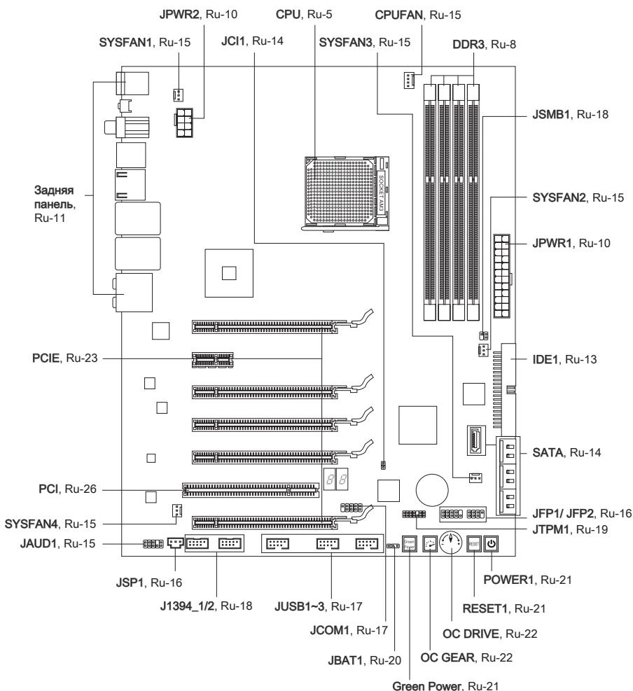
QUICK COMPONENTS GUIDE
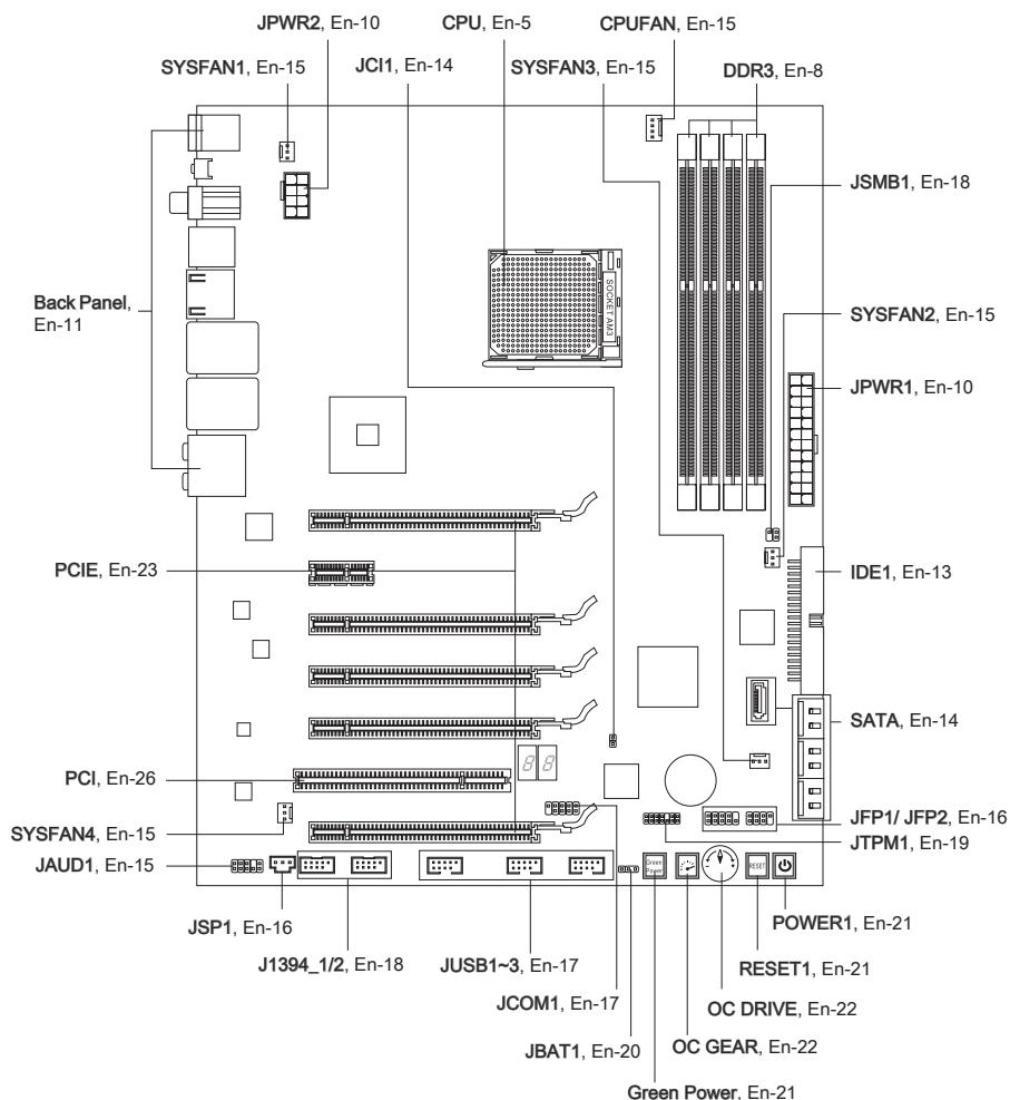
CPU (CENTRAL PROCESSING UNIT)
When you are installing the CPU, make sure to install the cooler to prevent overheating. If you do not have the CPU cooler, consult your dealer before turning on the computer. For the latest information about CPU, please visit http://www.msi.com/index.php?func=cpuform2
Important
Overheating
Overheating will seriously damage the CPU and system. Always make sure the cooling fan can work properly to protect the CPU from overheating. Make sure that you apply an even layer of thermal paste (or thermal tape) between the CPU and the heatsink to enhance heat dissipation.
Replacing the CPU
While replacing the CPU, always turn off the ATX power supply or unplug the power supply's power cord from the grounded outlet first to ensure the safety of CPU.
Overclocking
This mainboard is designed to support overclocking. However, please make sure your components are able to tolerate such abnormal setting, while doing overclocking. Any attempt to operate beyond product specifications is not recommended. We do not guarantee the damages or risks caused by inadequate operation or beyond product specifications.
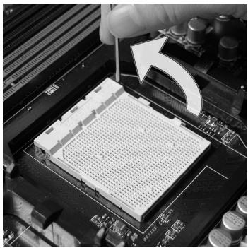
CPU & Cooler Installation
When you are installing the CPU, make sure the CPU has a cooler attached on the top to prevent overheating. Meanwhile, do not forget to apply some thermal paste on CPU before installing the heat sink/cooler fan for better heat dispersion.
Follow the steps below to install the CPU & cooler correctly. Wrong installation will cause the damage of your CPU & mainboard
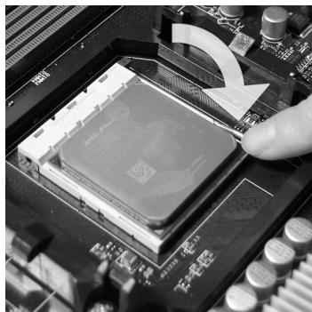
- Pull the lever sideways away from the socket. Make sure to raise the lever up to a 90-degree angle.
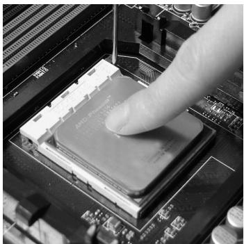
- If the CPU is correctly installed, the pins should be completely embedded into the socket and can not be seen. Please note that any violation of the correct installation procedures may cause permanent damages to your mainboard.
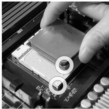
- Look for the gold arrow of the CPU. The gold arrow should point as shown in the picture. The CPU can only fit in the correct orientation.
- Press the CPU down firmly into the socket and close the lever. As the CPU is likely to move while the lever is being closed, always close the lever with your fingers pressing tightly on top of the CPU to make sure the CPU is properly and completely embedded into the socket.
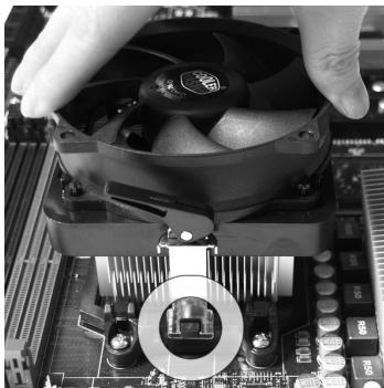
- Position the cooling set onto the retention mechanism.
Hook one end of the clip to hook first.
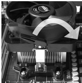
- Fasten down the lever.

- Then press down the other end of the clip to fasten the cooling set on the top of the retention mechanism.
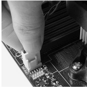
Locate the Fix Lever and lift up it.
- Attach the CPU Fan cable to the CPU fan connector on the mainboard.
Important
- Mainboard photos shown in this section are for demonstration only. The appearance of your mainboard may vary depending on the model you purchase.
- While disconnecting the Safety Hook from the fixed bolt, it is necessary to keep an eye on your fingers, because once the Safety Hook is disconnected from the fixed bolt, the fixed lever will spring back instantly.
MEMORY
These DIMM slots are used for installing memory modules. For more information on compatible components, please visit http://www.msi.com/index.php?func=testreport
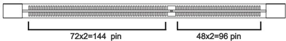
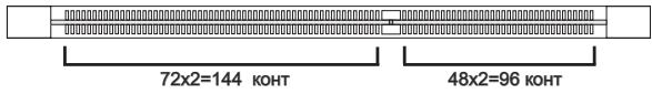
DDR3
240-pin, 1.5V
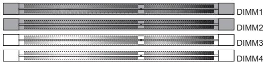
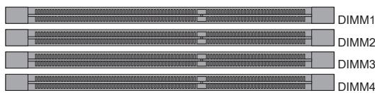
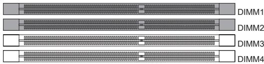
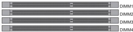
Dual-Channel mode Population Rule
In Dual-Channel mode, the memory modules can transmit and receive data with two data bus lines simultaneously. Enabling Dual-Channel mode can enhance the system performance. The following illustrations explain the population rules for Dual-Channel mode.


Important
- DDR3 memory modules are not interchangeable with DDR2 and the DDR3 standard is not backwards compatible. You should always install DDR3 memory modules in the DDR3 DIMM slots.
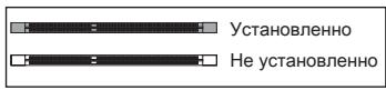
- In Dual-Channel mode, make sure that you install memory modules of the same type and density in different channel DIMM slots.
- To enable successful system boot-up, always insert the memory modules into the DIMM1 first.
- Due to the chipset resource deployment, the system density will only be detected up to 15+GB (not full 16GB) when each DIMM is installed with a 4GB memory module.
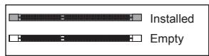
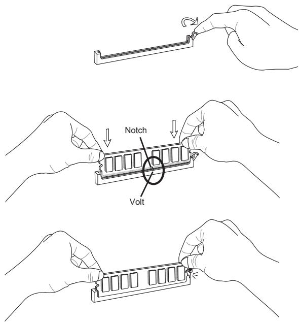
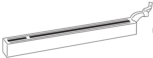
Installing Memory Modules
- The memory module has only one notch on the center and will only fit in the right orientation.
- Insert the memory module vertically into the DIMM slot. Then push it in until the golden finger on the memory module is deeply inserted in the DIMM slot. The plastic clip at each side of the DIMM slot will automatically close when the memory module is properly seated.
- Manually check if the memory module has been locked in place by the DIMM slot clips at the sides.
Important
You can barely see the golden finger if the memory module is properly inserted in the DIMM slot.
POWER SUPPLY
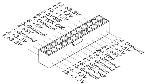
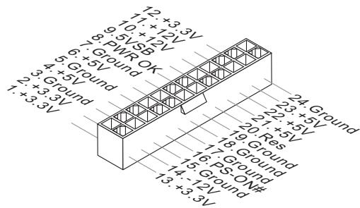
ATX 24-pin Power Connector: JPWR1
This connector allows you to connect an ATX 24-pin power supply. To connect the ATX 24-pin power supply, make sure the plug of the power supply is inserted in the proper orientation and the pins are aligned. Then push down the power supply firmly into the connector.
You may use the 20-pin ATX power supply as you like. If you'd like to use the 20-pin ATX power supply, please plug your power supply along with pin 1 & pin 13.
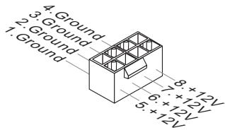
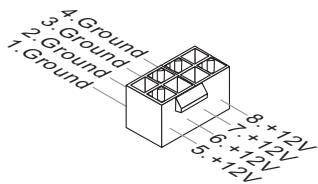
ATX 8-pin Power Connector: JPWR2
This connector is used to provide +12V power.
Important
- Make sure that all the connectors are connected to proper ATX power supplies to ensure stable operation of the mainboard.
- Power supply of 400 watts (and above) is highly recommended for system stability.
BACK PANEL
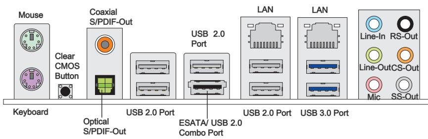
Mouse/Keyboard
The standard PS/2® mouse/keyboard DIN connector is for a PS/2® mouse/keyboard.
Clear CMOS Button
There is a CMOS RAM on board that has a power supply from external battery to keep the system configuration data. With the CMOS RAM, the system can automatically boot OS every time it is turned on. If you want to clear the system configuration, use the button to clear data. Press the button to clear the data.
Important
Make sure that you power off the system before clearing CMOS data.
After pressing this button to clear CMOS data in power off (G3) state, the system will boot automatically.
Coaxial S/PDIF-Out
This S/PDIF (Sony & Philips Digital Interconnect Format) connector is provided for digital audio transmission to external speakers through a coaxial cable.
Optical S/PDIF-Out
This S/PDIF (Sony & Philips Digital Interconnect Format) connector is provided for digital audio transmission to external speakers through an optical fiber cable.
USB 2.0 Port
The USB (Universal Serial Bus) port is for attaching USB devices such as keyboard, mouse, or other USB-compatible devices. Supports data transfer rate up to 480Mbit/s (Hi-Speed).
USB 3.0 Port
USB 3.0 port is backward-compatible with USB 2.0 devices. Supports data transfer rate up to 5 Gbit/s (SuperSpeed).
Important
If you want to use a USB 3.0 device, you must use the USB 3.0 cable to connect to the USB 3.0 port.
ESATA/USB2.0ComboPort
The ESATA/USB 2.0 combo port is for attaching the ESATA external hard drive or USB device.
LAN
The standard RJ-45 LAN jack is for connection to the Local Area Network (LAN). You can connect a network cable to it.

| LED | Color | LED State | Condition |
| Left | Yellow | Off | LAN link is not established. |
| On(Steady state) | LAN link is established. | ||
| On(brighter & pulsing) | The computer is communicating with another computer on the LAN. | ||
| Right | Green | Off | 10 Mbits/sec data rate is selected. |
| On | 100 Mbits/sec data rate is selected. | ||
| Orange | On | 1000 Mbits/sec data rate is selected. |
Audio Ports
These audio connectors are used for audio devices. It is easy to differentiate between audio effects according to the color of audio jacks.
- Line-In (Blue) - Line In, is used for external CD player, tape-player or other audio devices.
Line-Out (Green) - Line Out, is a connector for speakers or headphones. - Mic (Pink) - Mic, is a connector for microphones.
RS-Out (Black) - Rear-Surround Out in 4/5.1/7.1 channel mode.
CS-Out (Orange) - Center/ Subwoofer Out in 5.1/ 7.1 channel mode.
SS-Out (Gray) - Side-Surround Out 7.1 channel mode.
CONNECTORS
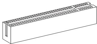
IDE Connector: IDE1
This connector supports IDE hard disk drives, optical disk drives and other IDE devices.
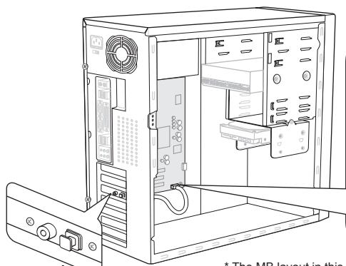
* The MB layout in this figure is for reference only.
Important
If you install two IDE devices on the same cable, you must configure the drives separately to master / slave mode by setting jumpers. Refer to IDE device's documentation supplied by the vendors for jumper setting instructions.
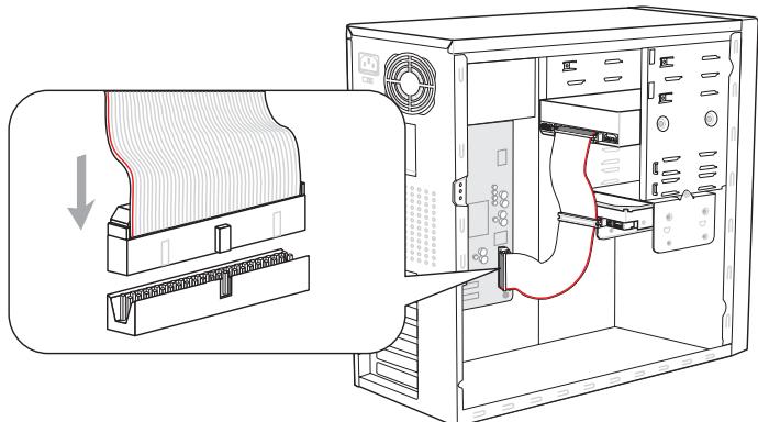
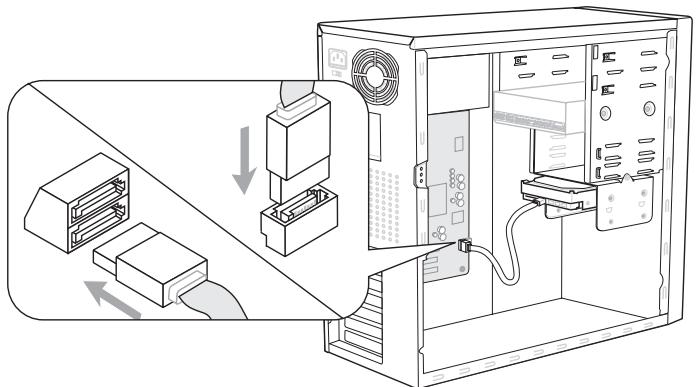
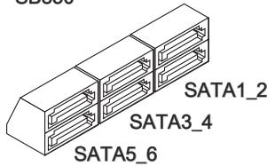
Serial ATA Connector: SATA1~7
This connector is a high-speed Serial ATA interface port. Each connector can connect to one Serial ATA device.
* The MB layout in this figure is for reference only.
SATA1~6 (6Gb/s)
supported by SB850
SATA7 (3Gb/s)
supported by JMB363
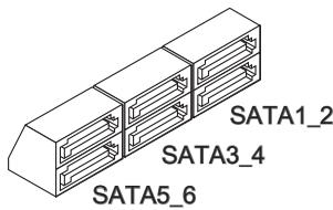

SATA7
Important
Please do not fold the Serial ATA cable into 90-degree angle. Otherwise, data loss may occur during transmission.
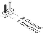
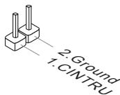
Chassis Intrusion Connector: JCI1
This connector connects to the chassis intrusion switch cable. If the chassis is opened, the chassis intrusion mechanism will be activated. The system will record this status and show a warning message on the screen. To clear the warning, you must enter the BIOS utility and clear the record.
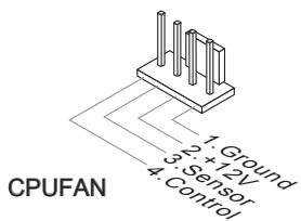
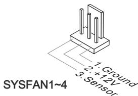
Fan Power Connectors: CPUFAN, SYSFAN1~4
The fan power connectors support system cooling fan with +12V . When connecting the wire to the connectors, always note that the red wire is the positive and should be connected to the +12V ; the black wire is Ground and should be connected to GND. If the mainboard has a System Hardware Monitor chipset on-board, you must use a specially designed fan with speed sensor to take advantage of the CPU fan control.


Important
- Please refer to the recommended CPU fans at processor's official website or consult the vendors for proper CPU cooling fan.
- CPUFAN supports fan control. You can install Control Center utility that will automatically control the CPU fan speed according to the actual CPU temperature.
- Fan cooler set with 3 or 4 pins power connector are both available for CPUFAN.
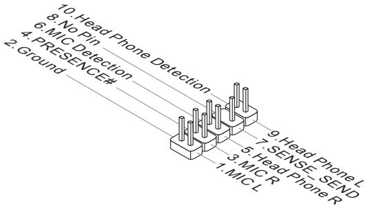
Front Panel Audio Connector: JAUD1
This connector allows you to connect the front panel audio and is compliant with Intel® Front Panel I/O Connectivity Design Guide.
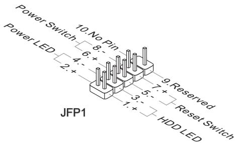
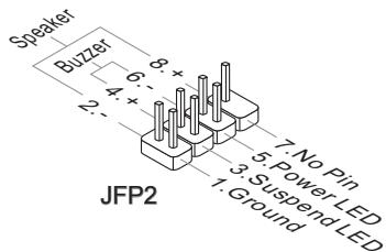
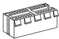
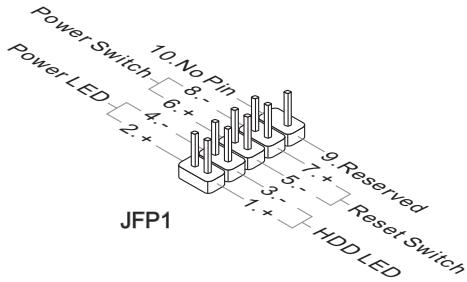
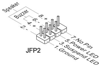
Front Panel Connectors: JFP1, JFP2
These connectors are for electrical connection to the front panel switches and LEDs. The JFP1 is compliant with Intel® Front Panel I/O Connectivity Design Guide.
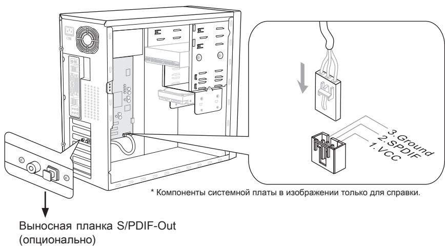
S/PDIF-Out Connector: JSP1
This connector is used to connect S/PDIF (Sony & Philips Digital Interconnect Format) interface for digital audio transmission.
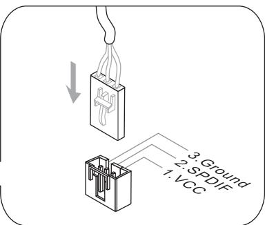
* The MB layout in this figure is for reference only.
S/PDIF-Out Bracket (optional)
Front USB Connector: JUSB1 / JUSB2 / JUSB3
This connector, compliant with Intel® I/O Connectivity Design Guide, is ideal for connecting high-speed USB interface peripherals such as USB HDD, digital cameras, MP3 players, printers, modems and the like.
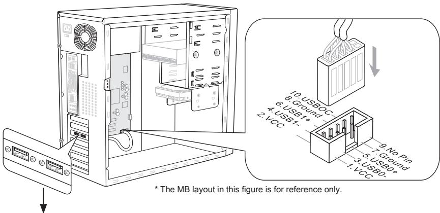
USB 2.0 Bracket (optional)
Important
Note that the pins of VCC and GND must be connected correctly to avoid possible damage.
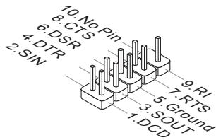
Serial Port Connector: JCOM1
This connector is a 16550A high speed communication port that sends/ receives 16 bytes FIFOs. You can attach a serial device.
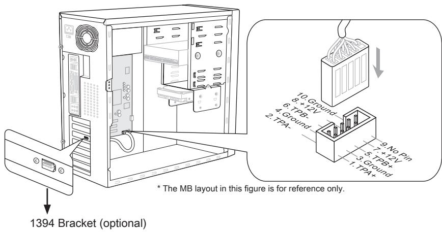
IEEE1394 Connector: J1394_1 / J1394_2
This connector allows you to connect the IEEE1394 device via an optional IEEE1394 bracket.
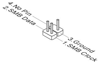
GreenPower Genie Connector: JSMB1 (optional)
This connector connects to GreenPower Genie (optional).
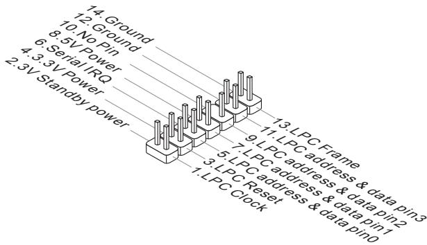
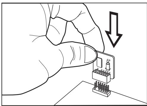
TPM Module connector: JTPM1
This connector connects to a TPM (Trusted Platform Module) module (optional). Please refer to the TPM security platform manual for more details and usages.
JUMPERS
Clear CMOS Jumper: JBAT1
There is a CMOS RAM onboard that has a power supply from an external battery to keep the data of system configuration. With the CMOS RAM, the system can automatically boot OS every time it is turned on. If you want to clear the system configuration, set the jumper to clear data.

JBAT1

Keep Data

Clear Data
Important
You can clear CMOS by shorting 2-3 pin while the system is off. Then return to 1-2 pin position. Avoid clearing the CMOS while the system is on; it will damage the mainboard.
BUTTON
The mainboard provides the following buttons for you to set the computer's function. This section will explain how to change your mainboard's function through the use of button.
Power Button: POWER1
This button is used to turn-on or turn-off the system. Press the button to turn-on or turn-off the system.
Reset Button: RESET1
This button is used to reset the system. Press the button to reset the system.

Green Power Button: Green Power
This button is used to switch LED function of system. Once you press the button, the system will switch the LED between on and off mode.

OC Dial Button and OC Dial Knob: OC GEAR & OC DRIVE
The button and the knob are used to adjust the FSB.

OC Dial Button: OC GEAR
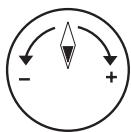
OC Dial Knob: OC DRIVE
You can use them to change FSB clock at any time under the operating system. This method does not need to install software or reboot. Please follow the steps below to increase or decrease the FSB clock.
- Press the OC Dial button to start adjustment. The OC Dial LED will light to indicate current operation.
- Turn the OC Dial knob clockwise/anti-clockwise to increase/decrease FSB clock. You can set the value of OC Dial Step in BIOS.
- Press the OC Dial button again to complete adjustment. The OC Dial LED will turn off automatically.
Important
- Before you use OC Dial function to overclock the system. In order to increase the success rate, you should set the voltage in BIOS properly.
- After each of the adjustments, this feature should be shut down. Otherwise, it would affect the system performance. Therefore, when you complete the adjustment, check whether OC Dial LED is on or off, if OC Dial LED is still lit, press the button and then check again.
SLOTS
PCIE (Peripheral Component Interconnect Express) Slot The PCI Express slot supports the PCI Express interface expansion card.

PCI Express x16 Slot
PCI Express x1 Slot
Important
When adding or removing expansion cards, make sure that you unplug the power supply first. Meanwhile, read the documentation for the expansion card to configure any necessary hardware or software settings for the expansion card, such as jumpers, switches or BIOS configuration.
ATI CrossFireX™ (Multi-GPU) Technology
ATI CrossFire™ is the ultimate multi-GPU performance gaming platform. Enabling game-dominating power, ATI CrossFire™ technology enables two or more discrete graphics processors to work together to improve system performance. ATI CrossFire™ technology allows you to expand your system's graphics capabilities. It allows you the ability to scale your system's graphics horsepower as you need it, supporting two or more ATI Radeon™ HD graphics cards, making this the most scalable gaming platform ever. The motherboard can auto detect the CrossFire™ mode by software, therefore you don't have to enable the CrossFire™ in BIOS by yourself. The following details the 2-way CrossFire™ installation.
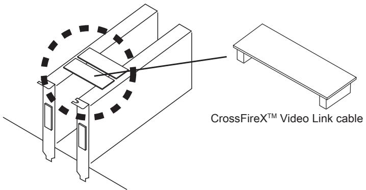
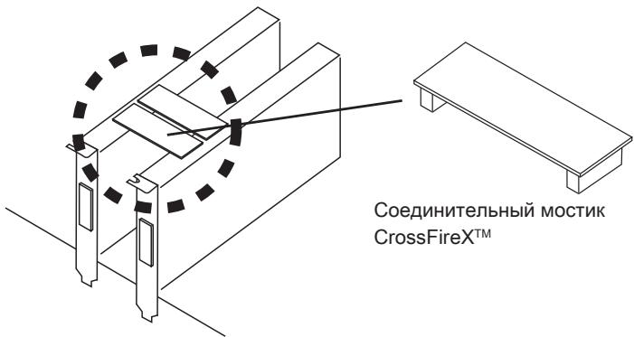
- Install two ATI Radeon™ HD graphics cards into two PCIe x16 slots except the PCI_E4 slot.
- With two cards installed, an CrossFire™ Video Link cable is required to connect the golden fingers on the top of these two graphics cards (refer to the picture below). Please note that although you have installed two or more graphics cards, only the video outputs on the graphics card installed in PCI_E1 will work. Hence, you only need to connect a monitor to this graphics card.
Important
- If you intend to install TWO graphics cards for CrossFire X^TM mode, make sure that: a. these two graphics cards are of the same brand and specifications; b. these two cards are installed on both PCIE x16 slots that support up to PCIE x16 speed.
- Make sure that you connect an adequate power supply to the power connector on the graphics card to ensure stable operation of the graphics card.
-
Only Windows® XP with Service Pack 2 (SP2)& Windows® XP Professional x64 Edition, Windows® Vista & Windows® 7 support the CrossFire™ function.
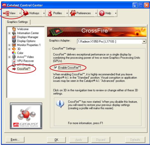
-
When all of the hardware and software has been properly set up and installed, reboot the system. After entering the O.S., click the "Catalyst™ Control Center" icon on the desktop. There is a setting in the Catalyst™ Control Center that needs to be enabled for CrossFire™ to operate. The following aspect appears in Catalyst™ Control Center:
Select the Advanced View from the view drop menu.

Important
A CrossFire™ system has four possible display modes:
SuperTiling
- Scissor Mode
Alternate Frame Rendering
- Super Anti-aliasing.
for more details, please consult the graphics card manual from the manufacturer.
PCI (Peripheral Component Interconnect) Slot
The PCI slot supports LAN card, SCSI card, USB card, and other add-on cards that comply with PCI specifications.

32-bit PCI Slot
Important
When adding or removing expansion cards, make sure that you unplug the power supply first. Meanwhile, read the documentation for the expansion card to configure any necessary hardware or software settings for the expansion card, such as jumpers, switches or BIOS configuration.
PCI Interrupt Request Routing
The IRQ, acronym of interrupt request line and pronounced I-R-Q, are hardware lines over which devices can send interrupt signals to the microprocessor. The PCI IRQ pins are typically connected to the PCI bus pins as follows:
| Order1 | Order2 | Order3 | Order4 | |
| PCI Slot1 | INT E# | INT F# | INT G# | INT H# |
LED STATUS INDICATORS
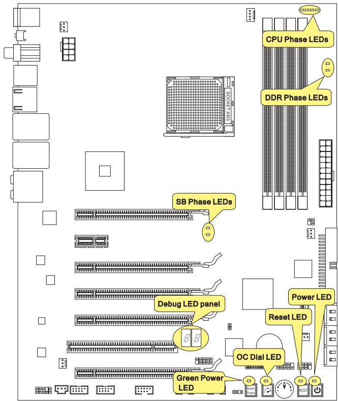
CPU Phase LED panel
These LEDs indicate the current CPU power phase mode. Follow the instructions below to read.

Lights

Off
| □□□□ | CPU is in 1 phase power mode. | □□□□ | CPU is in 2 phase power mode. |
| □□□□ | CPU is in 3 phase power mode. | □□□□ | CPU is in 4 phase power mode. |
SB Phase LEDs
These LEDs indicate the current SB power phase mode. Follow the instructions below to read.
Lights
Off
| □■ | SB is in 1 phase power mode. | ■■ | SB is in 2 phase power mode. |
DDR Phase LEDs
These LEDs indicate the current DDR power phase mode. Follow the instructions below to read.
Lights
Off
| □■ | DDR is in 1 phase power mode. | ■■ | DDR is in 2 phase power mode. |
Power LED
Lights blue when you press the Power button and it is functional.
Reset LED
Lights blue when you press the Reset button and it is functional.
Green Power LED
Lights blue when you press the Green Power button and it is functional.
OC Dial LED
Lights when you press the OC Dial button and it is functional.
Debug LED Panel
Please refer to the table below to get more information about the Debug LED message.
| Post | Status |
| FF | Power on and first initialize CPU. |
| C0, C1, C2 | Early CPU Initialize. |
| C4, C6 | Initialize chipset. |
| D4, D5 | Initialize memory. |
| 08 | Initialize keyboard. |
| 2A, 31 | Initialize onboard devices. Load Option ROM (VGA and RAID option ROM) from BIOS to memory. |
| 37 | Displaying sign-on message, CPU information, setup key message and any OEM specific information. |
| 38 | Initialize USB device and different devices. |
| 3C | Mid POST initialization of chipset registers. Detect different devices (parallel ports, serial ports and coprocessor in CPU...etc.) |
| 75, 78 | Initialize INT 13 devices and IPL devices. (include SATA/ PATA HDD and CD/DVD ROM). |
| 87 | Enter setup screen. BIOS setup if needed/ requested. |
| A4 | Wait for user input at configuration display if needed. |
| A7 | Display the system configuration screen if enabled. |
| B1 | Save system context for ACPI (Advanced Configuration and Power Interface).Prepare give control to OS loader (INT 19H). |
| 00 | Pass control to OS Loader (typically INT 19H). |
| AA | Enter OS. |
BIOS SETUP
This chapter provides basic information on the BIOS Setup program and allows you to configure the system for optimum use. You may need to run the Setup program when:
An error message appears on the screen during the system booting up, and requests you to run BIOS SETUP.
You want to change the default settings for customized features.
Important
- The items under each BIOS category described in this chapter are under continuous update for better system performance. Therefore, the description may be slightly different from the latest BIOS and should be held for reference only.
- Upon boot-up, the 1st line appearing after the memory count is the BIOS version. It is usually in the format:
A7640AMS V1.0 021410 where:
1st digit refers to BIOS maker as A = AMI , W = AWARD , and P = PHOENIX .
2nd - 5th digit refers to the model number.
6th digit refers to the chipset as I = Intel, N = NVIDIA, A = AMD and V = VIA.
7th - 8th digit refers to the customer as MS = all standard customers.
V1.0 refers to the BIOS version.
021410 refers to the date this BIOS was released.
Entering Setup
Power on the computer and the system will start POST (Power On Self Test) process. When the message below appears on the screen, press key to enter Setup.
Press DEL to enter SETUP
If the message disappears before you respond and you still wish to enter Setup, restart the system by turning it OFF and On or pressing the RESET button. You may also restart the system by simultaneously pressing
Getting Help
After entering the Setup menu, the first menu you will see is the Main Menu.
Main Menu
The main menu lists the setup functions you can make changes to. You can use the arrow keys (↑↓) to select the item. The on-line description of the highlighted setup function is displayed at the bottom of the screen.
Sub-Menu
If you find a right pointer symbol appears to the left of certain fields that means a submenu can be launched from this field. A sub-menu contains additional options for a field parameter. You can use arrow keys (↑↓) to highlight the field and press
General Help
The BIOS setup program provides a General Help screen. You can call up this screen from any menu by simply pressing
The Main Menu
Once you enter BIOS CMOS Setup Utility, the Main Menu will appear on the screen. The Main Menu allows you to select from the setup functions and two exit choices. Use arrow keys to select among the items and press
| Standard CMOS Features | Cell Menu |
| Advanced BIOS Features | M-Flash |
| Integrated Peripherals | Overclocking Profile |
| Power Management Setup | Load Fail-Safe Defaults |
| H/W Monitor | Load Optimized Defaults |
| Green Power | Save & Exit Setup |
| BIOS Setting Password | Exit Without Saving |
Standard CMOS Features
Use this menu for basic system configurations, such as time, date etc.
Advanced BIOS Features
Use this menu to setup the items of the BIOS special enhanced features.
Integrated Peripherals
Use this menu to specify your settings for integrated peripherals.
Power Management Setup
Use this menu to specify your settings for power management.
H/W Monitor
This entry shows your PC health status.
Green Power
Use this menu to specify the power phase.
BIOS Setting Password
Use this menu to set the password for BIOS.
Cell Menu
Use this menu to specify your settings for frequency/voltage control and overclocking.
M-Flash
Use this menu to read/ flash (or backup) the BIOS from (to) storage drive (FAT/ FAT32 format only).
Overclocking Profile
Use this menu to save/ load your settings to/ from CMOS for BIOS.
Load Fail-Safe Defaults
Use this menu to load the default values set by the BIOS vendor for stable system performance.
Load Optimized Defaults
Use this menu to load the default values set by the mainboard manufacturer specifically for optimal performance of the mainboard.
Save & Exit Setup
Save changes to CMOS and exit setup.
Exit Without Saving
Abandon all changes and exit setup.
When enter the BIOS Setup utility, follow the processes below for general use.
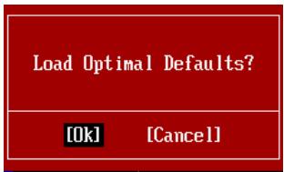
- Load Optimized Defaults: Use control keys ( ) to highlight the Load Optimized Defaults field and press < Enter>, a message as below appears:
Load Optimal Defaults?
[0k]
[Cancel]
Select [Ok] and press Enter to load the default settings for optimal system performance.
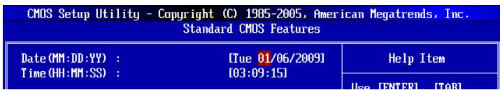
- Setup Date/ Time : Select the Standard CMOS Features and press
to enter the Standard CMOS Features-menu. Adjust the Date, Time fields.
- Save & Exit Setup: Use control keys ( ) to highlight the Save & Exit Setup field and press
, a message as below appears:

Select [Ok] and press Enter to save the configurations and exit BIOS Setup utility.
Important
The configuration above are for general use only. If you need the detailed settings of BIOS, please see the English manual on MSI website.
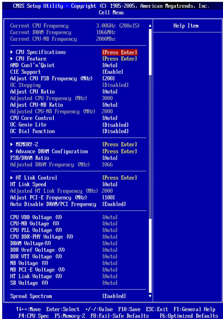
- Cell Menu Introduction : This menu is for advanced user who want to overclock the mainboard.

Current CPU / DRAM / CPU-NB Frequency
These items show the current clocks of CPU, Memory and CPU-NB speed. Read-only.
CPU Specifications
Press
CPU Technology Support
Press
CPU Feature
Press
AMD Cool'n'Quiet
The Cool'n'Quiet technology can effectively and dynamically lower CPU speed and power consumption.
Important
To ensure that Cool'n'Quiet function is activated and will be working properly, it is required to double confirm that:
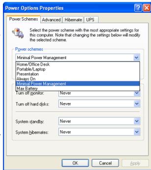
- Run BIOS Setup, and select Cell Menu. Under Cell Menu, find AMD Cool'n'Quiet, and set this item to "Enabled".
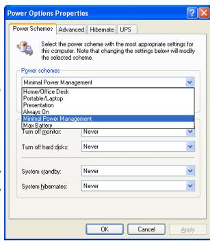
- Enter Windows, and select [Start]->[Settings] ->[Control Panel]->[Power Options]. Enter Power Options Properties tag, and select Minimal Power Management under Power schemes.
C1E Support
To enable this item to read the CPU power consumption while idle. Not all processors support Enhanced Halt state (C1E).
SVM Support
This item is used to enable/ disable SVM.
AMD Cool'n'Quiet
The Cool'n'Quiet technology can effectively and dynamically lower CPU speed and power consumption.
C1E Support
To enable this item to read the CPU power consumption while idle. Not all processors support Enhanced Halt state (C1E).
Adjust CPU FSB Frequency (MHz)
This item allows you to select the CPU Front Side Bus clock frequency (in MHz).
OC Stepping
This item will be enabled after you set the overclocking frequency in the "Adjust CPU FSB Frequency (MHz)". And the following items will appear. This items will help the system to overclock step by step after system booting up.
Start OC Stepping From (MHz)
This item is used to set the initial FSB clock. The system will boot with the initial FSB clock, and start to overclock from initial FSB clock to set FSB clock that you set in "Adjust CPU FSB Frequency (MHz)" step by step.
OC Step
This item is used to set how many steps for FSB colck overclocking.
OC Step Count Timer
This item is used to set the buffer time for every step.
Adjust CPU Ratio
This item is used to adjust CPU clock multiplier (ratio). It is available only when the processor supports this function.
Adjusted CPU Frequency (MHz)
It shows the adjusted CPU frequency. Read-only.
Adjust CPU-NB Ratio
This item is used to adjust CPU-NB ratio.
Adjusted CPU-NB Frequency (MHz)
It shows the adjusted CPU NB frequency. Read-only.
CPU Core Control
This item allows you to select the number of active processor cores.
OC Genie Lite
Setting this item to [Enabled] allows the system to detect the maximum FSB clock and to overclock automatically. If overclocking fails to run, you can try the lower FSB clock for overclocking successfully.
OC Dial Function
This item allows you to enable/disable the OC Dial function. Setting to [Enabled] activates the following fields, and use the following fields to set each OC Dial function.
OC Dial Step
This item is used to set value of each step when you rotate the OC dial knob.
OC Dial Reset
Select [Reset] if you need to reset the OC Dial Value.
OC Dial Value
This item indicates the overclocking value by OC dial function. When you rotate the OC dial knob, this value will change.
OC Dial Adjusted FSB Clock (MHz)
It shows the adjusted FSB clock by OC Dial function (FSB Clock +OC Dial Value). Read-only.
Memory-Z
Press
DIMM1~4 Memory SPD Information
Press
Advance DRAM Configuration
Press
DRAM Timing Mode
This field has the capacity to automatically detect all of the DRAM timing.
DRAM Drive Strength
This item allows you to control the memory data bus' signal strength. Increasing the drive strength of the memory bus can increase stability during overclocking.
DRAM Advance Control
This field has the capacity to automatically detect the advanced DRAM timing. If you set this field to [DCT 0], [DCT 1] or [Auto], some fields will appear and selectable.
1T/2TMemory Timing
This item controls the SDRAM command rate. Select [1T] makes SDRAM signal controller to run at 1T (T=clock cycles) rate. Selecting [2T] makes SDRAM signal controller run at 2T rate.
DCT Unganged Mode
This feature is used to Integrate two 64-bit DCTs into a 128-bit interface.
Bank Interleaving
Bank Interleaving is an important parameter for improving overclocking capability of memory. It allows system to access multiple banks simultaneously.
Power Down Enable
This is a memory power-saving technology. When the system does not access memory over a period of time, it will automatically reduce the memory power supply.
MemCik Tristate C3/ATLVID
This setting allows you to enable/disable the MemClk Tristating during C3 and ATLVID.
FSB/DRAM Ratio
This item allows you to select the ratio of FSB/ DRAM.
Adjusted DRAM Frequency (MHz)
It shows the adjusted Memory frequency. Read-only.
HT Link Control
Press
HT Incoming/Outgoing Link Width
These items allow you to set the Hyper-Transport Link width. Setting to [Auto], the system will detect the HT link width automatically.
HT Link Speed
This item allows you to set the Hyper-Transport Link speed. Setting to [Auto], the system will detect the HT link speed automatically.
Adjusted HT Link Frequency (MHz)
It shows the adjusted HT Link frequency. Read-only.
Adjust PCI-E Frequency (MHz)
This field allows you to select the PCIE frequency (in MHz).
Auto Disable DRAM/PCI Frequency
When set to [Enabled], the system will remove (turn off) clocks from empty DRAM/PCI slots to minimize the electromagnetic interference (EMI).
CPU VDD Voltage (V)/CPU-NB VDD Voltage (V)/CPU Voltage (V)/CPU-NB Voltage (V)/CPU PLL Voltage (V)/CPU DDR-PHY Voltage (V)/DRAM Voltage (V)/DDR Vref Voltage (V)/DDR VTT Voltage (V)/NB Voltage (V)/NB PCI-E Voltage (V)/HT Link Voltage (V)/SB Voltage (V)
These items are used to adjust the voltage of CPU, Memory and chipset.
Spread Spectrum
When the mainboard's clock generator pulses, the extreme values (spikes) of the pulses create EMI (Electromagnetic Interference). The Spread Spectrum function reduces the EMI generated by modulating the pulses so that the spikes of the pulses are reduced to flatter curves.
Important
- If you do not have any EMI problem, leave the setting at [Disabled] for optimal system stability and performance. But if you are plagued by EMI, select the value of Spread Spectrum for EMI reduction.
- The greater the Spread Spectrum value is, the greater the EMI is reduced, and the system will become less stable. For the most suitable Spread Spectrum value, please consult your local EMI regulation.
- Remember to disable Spread Spectrum if you are overclocking because even a slight jitter can introduce a temporary boost in clock speed which may just cause your overclocked processor to lock up.
SOFTWARE INFORMATION
Take out the Driver/Utility DVD that is included in the mainboard package, and place it into the DVD-ROM drive. The installation will auto-run, simply click the driver or utility and follow the pop-up screen to complete the installation. The Driver/Utility DVD contains the:
- Driver menu : The Driver menu shows the available drivers. Install the driver by your desire and to activate the device.
- Utility menu : The Utility menu shows the software applications that the mainboard supports.
Important
Please visit the MSI website to get the latest drivers and BIOS for better system performance.
890FXA-GD70
Serie
Deutsch
SPEZIFICATIONEN
Prozessoren
Green Power Taster: Green Power
SuperTiling
- Scissor Mode
Alternate Frame Rendering
Super Anti-aliasing.
| Standard CMOS Features | Cell Menu |
| Advanced BIOS Features | M-Flash |
| Integrated Peripherals | Overclocking Profile |
| Power Management Setup | Load Fail-Safe Defaults |
| H/W Monitor | Load Optimized Defaults |
| Green Power | Save & Exit Setup |
| BIOS Setting Password | Exit Without Saving |
Standard CMOS Features
Advanced BIOS Features
Integrated Peripherals
BIOS Setting Password
Load Optimal Defaults?
[0k]
[Cancel]
CPU Technology Support
Adjust CPU FSB Frequency (MHz)
Start OC Stepping From (MHz)
Adjusted CPU Frequency (MHz)
Adjusted CPU-NB Frequency (MHz)
OC Dial Adjusted FSB Clock (MHz)
Adjusted DRAM Frequency (MHz)
HT Incoming/Outgoing Link Width
Adjusted HT Link Frequency (MHz)
Adjust PCI-E Frequency (MHz)
SuperTiling
- Scissor Mode
Alternate Frame Rendering
Super Anti-aliasing.
Emplacement PCI (Peripheral Component Interconnect)
SB Phase LEDs (LEDs Phase SB)
OC Dial LED (LED OC Dial)
| Standard CMOS Features | Cell Menu |
| Advanced BIOS Features | M-Flash |
| Integrated Peripherals | Overclocking Profile |
| Power Management Setup | Load Fail-Safe Defaults |
| H/W Monitor | Load Optimized Defaults |
| Green Power | Save & Exit Setup |
| BIOS Setting Password | Exit Without Saving |
Standard CMOS Features (Fonctions CMOS standard)
Load Optimal Defaults?
[0k]
[Cancel]
Save configuration changes and exit setup?
[0k]
[Cancel]
CPU Technology Support
Adjust CPU FSB Frequency (MHz)
Start OC Stepping From (MHz)
Adjusted CPU Frequency (MHz)
Adjusted CPU-NB Frequency (MHz)
HT Incoming/Outgoing Link Width
Adjusted HT Link Frequency (MHz)
Adjust PCI-E Frequency (MHz)
CPU VDD Voltage (V)/CPU-NB VDD Voltage (V)/CPU Voltage (V)/CPU-NB Voltage (V)/CPU PLL Voltage (V)/CPU DDR-PHY Voltage (V)/DRAM Voltage (V)/DDR Vref Voltage (V)/DDR VTT Voltage (V)/NB Voltage (V)/NB PCI-E Voltage (V)/HT Link Voltage (V)/SB Voltage (V)
Pa3bEmbl, yCTaHOBJIeHHIe Ha IJIaTe
- 3 pa3bema USB 2.0
- 2 pa3bema IEEE 1394
- 1 pa3bemДaTUnKa OTKpbIbAHnK KOpnyCa
- 1 pa3bem S/PDIF-out
- 1 pa3bemдя поdklouehn aydno Ha nepeDne nane
-1pa3bEmTPMMoyn
-1 KhoNka NHTaHnA
-1 KhoNka Reset - 1 KhoNka OC Dial
- 1 perynatop OC Dial
- 1 KhoNka Green Power
- 1 naneB nndkaTopa Debug LED
CnotbI
4 cnoTa PCI Express 2.0 x16, noDpeKka ckopocTn do PCIE 2.0 x16
1 cnotPCI Express 2.0 x16, noidepka ckopoctno PCIE 2.0 x4 (PCI_E4)
1 cnot PCI Express 2.0 x1
1 cnot PCI, nOndepkka INHTeppeca PCI uHbI c nTahnem 3.3V/5V
ΦopM ΦakTop
ATX (24.5cm X 30.5 cm)
Kpenenne
9 TBepctn dna KpeenneHna
XapakTepeNCTnO Focus
USB 3.0
SATA 6Γ6/c
DrMOS BnTyprn
Half Hi-C Cap dɪn3aɪn
Active Phase Switch feature Дя заюни рпаньдИнhamнHO
OC Genie Lite
OC Dial
Easy Button 2
USB Safeguard
BkIouyam-Flash
CrossFireX™
POMOuB B pnpo6peTeHIN DOnOpHnHTeHbIX akceccyapOB n noncke Homepa n3dJIa MOKHO NaHTI NO aDpecy
http://www.msi.com/index.php
PA3MEUEHNE KOMHOHETOB CNTEMHOIJIATBI
CPU (LHTPAJIbHbI IPOUCECCOP)
- 06paTInTe BHNMaHne Ha 3oIOnTyO CTpeNky (gold arrow) Ha CPU. OHa DOnJxHa 6bITb paCnONoXeHa TaK, KaK nOKa3aHo Ha pncyHke. CPU MoXHO BCTaBtB TOnbKO npn erO npaBnBHOOpNEHTaCmN.

- AkkypaTHOpnpKmnte CPU kpa3bemy n onyctnTe pbluayok. NockoJbky CPU npn onyckanH pbluaykma MoXeT nepemecTbC8, octopoxHo npKmTe CPU naIbcaMn B ceHTpe TaK, yTo6bl OH npabNlBHO n noJIHOCTbO 3aФNKcnpOBaNCB pa3beme.

- Pa3mecnte BENTnIaTOp Ha y3ne KpePnEnH.N.Bhaaane 3aueNITe OINH erO kpaI.

- 3aФикс neuropу Te paДиТОрдальншIM NOBOPOTOM pbHura.
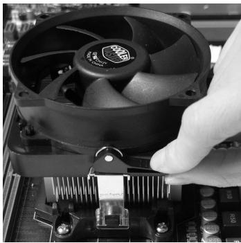
- 3aTeM haxmnte Ha dpyroI kpaI, yTo6bl yCTaHOBnTb paDnatOp Ha y3en KpenJIeHnIy. HauNTe pbUar fHKcaunn I NOHNMIte erO.

- ПоdkночиTe Ka6eJIb BeHTnIЯTopa CPU K COOTBeTCTByIOUeMy pa3bemy cnCTeMHoN PnAToBtI.

BHIMAHWE
- FOToRpaФnN CnCTeMHo NnAToB B 3ToM pa3DJIe NpUBeDEHbI TOnbKO nIaI DEMOHcTpaCm. BHeuHn BnD BaSei MoDeHn MoKeT OTnNuHaTcR O T npUBeDeHHO 3deCb.
- Пи OTcoeHHeHnФИKcPuyUeRo pIyara Heo6XoJMo CObIoudaTb OCTOpOxHocTb,Тak KAKpbIarNoIpyKuHEn I npI OTnyCkAHn OH BepHETcC NcXoJHoeNoIooKeHne.
PAMrTb
CnoTb DIMM nCnOJb3yIOTcI yCTaHOBKn MOyIe NAMrTn. 3a DOnONHHTeJIbHOI INΦoPmaIeN O COBMeCTmblx KOMNoHEHTax ObpaTntEc b Ha caIT
http://www.msi.com/index.php?func testreport
DDR3
240-koHT,1.5V
IpaBnla yCTaHOBKn MOyJNe NpamrTn Ipn pa60tbl B DbyXkHaJIbHOM pexmme
B DByxKaHaJIbHom pexIme moyI ni namrtn Moryt nepeDaBaT i npHIMaTb daHHbe no 2 uHAm oHOBpeMeHHo. PnncnoJb3ObaHHn DByxKaHaJIbHO r peXIMa npOn3BOJNTeJIbHOCTb cnCTembl NObIaaeTcH. Hxke npuBeJeHb IpabUNa 3aONHeHHN cLOTob nAMrT dIpaBoTb B DByxKaHaJIbHOM pexIMe.


BhimhaHne
- Moун DDR3 He B3aHmO3aMeHЯeMbI c MoулЯm DDR2, И стадг T DDR3 He Umeet obpaTHoN coBmecTmocTn. CneyuET BCerda yctaHaBnBaTb Moун пamrTn DDR3В pa3bEmbl DDR3 DIMM.
-Дя pa6obTbI B DByXKaHaJIbHOM pexMme y6eJntEcB,чTO B pa3beMax pa3HbIX KaHaJIIOB y Bac yCTaHOBJHeHb MOdyJIn OJHOro Tnna INOnHaKOBoE MKOCTN. - UTo6bI CuTeMa 3aRpyuHJnAcB, BhauaJIe yCTaHOBIne MoUJI N pa3bEm DIMM1.
- 13-3a cneuФнк npacpeJeHnna CnCTeMHbIX pecypcoB YInCeTa, obEIM IOcTynHOI pAMrTO MoKeT MaKcMauJIbHo CoCTaBHTb 15+ΓБ (Ho He 16ΓБ) npi yctaHOBKe MOdyNeI pAMrTo 4ΓБ b KaKdIb N3 CNOTOB.
YCTaHOBka MoJyIe IamrTn
- MoDyIi namrTn HmeHOT OndHy npope3b B cpeHneY cactN. MoDyIb BOJETB pa3beM TOnbko pRn PpaBnblHoN opHeNTaun.
- BCTaBbTe MoDyIb B DIMM cnot B BePtnKaIbHom HnPaBneHn. 3aTeM hAkmite Ha Hero, yTO6bI 30NoeHbIe KOHTaKbI rny6Oko nOrpy3uInc b DIMM cnot. Ecnn MOyIb pAmrTn BCTaBNeH npaBnIbHO, To nlaCTNKOBbIe 3aueJkn Ha oboux KOHcax 3akpoOTcABOMaTHueckn.
- BpyuHy u6eIntecb, yTo MoDyIb 3aKpeIenneB Cnote DIMM 3aUeIkamn c o6eHX CTOpOH.
BhimaHne
30JIOIe KOHTaKbI eDBA BnHbI, ecN MoUyn IamrN IpabuNbHO pa3MeueHbIBDIMM cnoTe.

PA3bEM IITAHIN
24-KoHTaKTbIpa3bEMATX:JPWR1
3TOT pa3bem NO3BONJET NOKNIQUHTb 24-KOHTAKTHbI KOHKeTOp NITAHNr ATX. IJIra erO NOKJIIOUChENy y6eINTEcB, YTO KOHKeTOp IN KOHTaKTbI pa3bema npabINbHO copHeHTnPOBaHbI. 3aTeM NlOTHO BCTABBe erO B pa3bem HA CNTeMHo NlATE.
BbI TAKKe MoKTe NcNoJIb3OBAtB 20-KoHTaKTHbIy ATX 6nok nTahnI. PpN IcNoJIb3OBAHmN 20-KoHTaKTHOro pa3bema, NOdJIIOUaMye erO BDoJI KoHTaKToB 1 n 13.
8-KoHTaKThbI pa3bem nHTaHnA TX: JPWR2
3TOT pa3bem nHTaHn IcNoIb3yETc dIy oBecneueHn nHTaHn npOeccopa 12V.
Bhimahine

* KomnoHeTbI CnCTeMHoI pIaTb I N3O6paKeHm TOnbKO dIy cnpaBkM.
SATA1~6(6Γ6/c)
pa6oTaIOT Ha YInCeTe
SB850
SATA7 (3Γ6/c)
pa60taet Ha YInncete
JMB363
SATA7
BHIMAHINE
U36eraIte, noKanyIcTa, pe3Knx u3rNbOB Ka6eIa Serial ATA. B npoTnBHom clyuae MOryT Bo3HnKHyTb nOtePn daHHbIX npi nepeDaue.
Pazbem daTunka otKpbBaHnna Kopnyca: JCI1
K 3TOMY KOHNHeKToPny PNOKnIHyOaTeC KabeJI DaTuNka, yCTaHOBNeHORo B Kopnyce. Ptni OTKpbIBaHm KOpNyca erO mexAHn3M aKTNBn3npyeTc. CnCTema 3anOMHaet 3TO c6bItne n BbIaet npEynpeJxdeHne Ha ekpaH. PpeynpeJxdeHne MoXHO OTKJIouHTb B HacTpOikax BIOS.
Pazbem nitaHn BENTNIJrTopoB:CPUFAN, SYSFAN1\~4
Pa3bEmblNTaHnBEHTNlAToPBO NOdepKnaBaOT BEHTNlAToPbC nTtAHmE +12B. PnnoKIOUeHNHeO6xOJMO NOMHnTB, YTO KpachbI NPOBOID NOkKnIOuaeTcK WnHe +12B, YepHbI - K 3emIe GND. EcnHa CnCTeMHo INaTe yCTaHOBeMaMKpocXema annapatHoro MOHToPunHra, He06xOJMoNcNoJIb3OBA Tb CneuaJIbHbIe BEHTNlAToPbC daTUnKaMn CKOpOCTn DnpeaJIIN3aUIn ΦyHKUIn ynpabJIeHn BeHTNlAToPamn.
BHIMAHWE
- UTo6bI y3HaTb O MoDeJIaX IOxOJaXuX BeHTnIaTOpOB, o6paTITcB, IoxaIyIcTa, Ha OΦnIaJIbHbI Be6 caNTnI npOKOHcyIbTnpUyIcB c npOdaBcM.
- CPUFAN noДержиBaet упаьнения скорстю врашени вентлгота. Ддя АВТOMATУСЕСКOrO KOHTponЯ скорстю вентлгота поцecсopa, зависец OT Temператypы поцecсopa и сИстмы, можно установ� Control Center.
Pa3bemCPUFAN noDpeKnBaet BeHTnIaTOpbl, KaC 3, TaK n C 4 KOHTaTAMN.
BbHocHoi pa3bem aydno: JAUD1
ТOT KOHNEKTOP NO3BOJARET NOДКЛЮЧТБ ВИССОН pa3bEМ aydno Ha nepeДнй панени и COOTBECTByET pykoBoDCTBy Intel® Front Panel I/O Connectivity Design.

KoHneKTopbI nepeDHeN paHeN: JFP1, JFP2
3TN KOHHeKTopbI NcNoJIb3yIOTcI dIe NIOKIIIOUeHnI KHOJOK I INHdIKaTOpOB, paCNOJoxeHHbIX Ha nepeDneI naHeIi Kopnyca. KOHHeKTop JFP1 COOTBeTCTByet pykoBoIDCTBy Intel® Front Panel I/O Connectivity Design.
Pazem S/PDIF-Out: JSP1
3ToT pa3bem nCnoNb3ayTc dIy noDknHoueHn HntepFeca S/PDF (Sony & Philips Digital Interconnect Format) dIy nepeaun 3Byka B zuΦpOBom φopMaTe.
3Ta KhoNka IcNoIb3yeTcA IJI BKJIIOUeHnI N BbIKJIIOUeHnI CnCTeMbI. HaxMnte 3Ty KHOKNy, YTO6bI BKIIIOHtB IJIN BbIKJIIOUHTb CnCTeMy.
KhoNka nepe3arpy3kn: RESET1
3Ta KhoNka IcNoIb3yETcA dIa nepe3arpy3Kn CnCTeMbI. HaxMITE 3Ty KHOKNy, YTO6bl nepe3arpy3NTb CnCTeMy.

KhoNka Green Power:Green Power
3Ta KhoNka NcNoJIb3yETcra IJnI N3MeHEnHpeXmMa pa6Otbl INdIkAToPob (LED) CnCTeMbI. PIn HaxKaTIN KHOKN CnCTema BKJIIOUaET/BbIKJIIOUaET INDkAToPbIe CBETOINObl.

Khoika OC Dial n Peryjatop OC Dial: OC GEAR & OC DRIVE
3ta Khonka n perynapot nncnolb3yioTc nn yctaHOBKn FSB.

Khonka OC Dial: OC GEAR
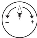
PerynTop OC Dial: OC DRIVE
3TN KOMNHOENTbI N03BOJHOT I3MeHApTb YactOry FSB BJIIO6oe Bpemr npri 3aRpyKeHHoI OepauOnHOHcNCTeMe. UctAHOBka DOnOpHNHeTbHoro IIO INn pepe3aRpy3Ka cNCTeMbI He Tpe6yETc. CLeDyInTe yka3aHnM HnKx dnn I3MeHEnra TaKTobOu YactOTbl.
- 3TN KOMNHOENTbI N03BOJIAOT N3MeHЯr Tb YactOry FSB B JIO6oe Bpem np 3arpykEHHo ONepaunOHHO CnCTeMe. YcTaHOBka DOnOpHNHeJIbHorO IIO nIN nepe3arpy3Ka CnCTeMb He Tpe6yETc. CneNyTe yka3AHm HnKe dIy N3MeHEnra TAKTOBoi YacTOfbl.
- Поворачива对接угларOTOC Dial no yacobойстрелк/прOTь усавоь стpeлдду велченя/уменшени FSB. Ⅲgar n3mehenя чаToTb мохно уctahOBNTbВBIOS.
- Haxmte KhoNky OC Dial eue pa3, yTo6bl 3aKoHnTb peRyInpOBky. INnKaTop OC Dial BbIKIOuHTcA bTOMaTnueckn.
BHIMAHWE
- Ipeed nCpOJIb3OBAHHeM fYHKmU OC Dial, peKOMeHdyeTc npAByIbHo yCTaHOBtB COOTBeTCTByUOuNe HapJxKeHnB B BIOS dIyIyUWeHnB Bo3MOxHocTn pa3roHa.
- Iocne yctahOBKn HacTPOeK, fynHcIy O63aTeJIbHO DoJNkHa 6bITb BbIKNoyeHa. B npOTNBHom cIyueae 3TO MoKeT HeRaTHBNO NOBnIaTb Ha npON3BOUnteJIbHOCTb CnCTembl. N03tOMy nOOKHuaHn peRynIpOBKn, npOBepbTe COCToHne INDnKaTopa OC Dial, ecn OH ne BbIKNoueH, To haxMnTe KhoNky eJe pa3 n npOBepbTe COCToHne CHOba.
CJOTbl
Cnot PCIE (Peripheral Component Interconnect Express)
CnotPCIExpressnoDdepKnaeTkapTbIpacunpeHnIHTepeCaPCIExpress.
PCI Express x16 cnot

PCI Express x1 cnot
Bhuvahine
Ipeed yctahOBko nnnn 13BneHennem Kapr pacuHepnna ybeDntecb, yto Ka6ebnIITAHN OTKIOUeH OT 3NEKTPnuuecko CETn. IpoouTte DOKymEnTaunHO ha KapTy pacuHepnna IN BbINONHTE HeO6XODIMbIe annpaTHbIe nn nporpaMHbIe yCTAHOBKn Iy daHHo IIaTbI, TaKne KAK nepembyKN, nepeknOuaTeIIN NIKOHqrypaunIO BIOS.
Texhonoria ATI CrossFireX™ (Multi-GPU)
ATI CrossFireXTM obecneuBaeT BO3MOxHocb co3dAnnHaH6OJIe MoUhIx multi-GPU nroPobbx npatfopm. ATI CrossFireXTM no3BOJraTe DByM nn6oJIe rpaOnueckn mnpouceccopam pa6oTaB BmecTe dnyyBeJIuYeHn 3D-npOn3BODntelbHOCTn npedeocTabrRe T BO3MOxHocb noCTeNEHHORo Mac7a6nPoBaHn rpaOnuecko nOcncTeMb, no3BOJRA do6abTb DoONHtEnbHbIe aanTpBei ATI RadeonTM HD no Mepe Heo6xOUMocTN. CnCTemHna INaTAMoKet ATOmatueckn OpeDeNtB haNUnHe KOHnpyaunn CrossFireXTM nporpammhIMn CpeCTBaMn, no3Tomy DoONHtEnbHbIX hAcTpoek BVOS He Tpe6yetc. CJeNyTe daHbIM yka3aHnM nLa CO3DAHn CnCTembl CrossFireXTM n3 Dbyx BnuDeokaprt.
- YctaHOBnTE DBe BnDeOkaPbI ATI RadeonTM HD B o6o cNoTa PCIE x16 Kpome cNoTa PCI_E4.
- YctaHOBnTe MoCTNK CrossFireXTM Ha KOHTaKTbIe pa3bEmbl BBepy BuDeOkaPT (cmOTpnte n3o6paXeHne Hnke). O6paTnTE BHNMaHne, YTO XOTy UcTaHOBJIeHbI DBe IJIN 6oJee BuDeOkaPT, pa60aTt TOJbKO BuDeOBxOdbI Ha BeDyUe KaPte, N03TOMy MOHITOP CNeDuYe TNOKJIuOuTaB ToJbKO K HeI.
BHIMAHWE
- Ecnn Bbl cobupaetebc yctahOBNTb DBe BnDeoKapTb I B pexkme CrossFireXTM, ybeintecb B TOM, YTO:
a. 3TN BnDEOKapTbI CdEJaHbI ODNHM PpOu3BOUnteJIeM I NMeIoT OOnHaKOBbIe CneuΦnKaζu;
b. 3TN BnDEOKapTbI yCTaHOBHeHbIB O6oNX CnoTx PCIE x16, NOIDepKINBaIOxckOpocTb Do PCIE x16.
- Y6eHntecb, yTO y BAC oBcnepeHo DoCTaTOHoe NITAHne uepe3 DonONHnTeIbHbI pa3bem nITaHnHa H BuDeOkaPte dJa oBcnepeHnE ee CTaBnHO pa60tbi.
-
Фун的游戏 CrossFire™ подержимаетс с тольков Windows® XP with Service Pack 2 (SP2)& Windows® XP Professional x64 Edition, Windows® Vista & Windows® 7.
-
Поссе установский Сбero anecdapathoroi и рогамmaro obecne�еня, поразугшему. Поссе вхда в onepaioHHUcStemy, klnkhnte 3naoyok "Catalyst™ Control Center" B сnstemno obnaactn nahein 3aadaq. Дярабтб CrossFireX™ вamyнжно bknIOHTb onuIO CrossFireX™, koTopar haxodITcR B Catalyst™ Control Center (cm. n3obpaxeHne Hnke):
Bb6epTe Advanced View n3 the view drop menu.
BHMAHue
CnTeMaHa6a3eCrossFireXTM moKet pa60TaB B 4 peKImMax:
SuperTiling
- Scissor Mode
Alternate Frame Rendering
Super Anti-aliasing.
3a dononHnteBHOH nHOpMauei o6paTntEc b K pyKoBOcTBy noIb3OBaTeJIr O T npOn3BOuNTeJI BnDeOkaTpbl.
Cnot PCI (Peripheral Component Interconnect)
CnotPCIno3B0nraerytcaHOBntbkapTbLAN,SCSI,USBnDpyneDOnonHnTeIbHbIe KapTbpaSInpeHnA,KOTOpBIE COOTBeTCTByIOT cneunqkaunPCl.
32-bit PCI cnot
BHUMAHWE
Ipeud yctahOBko nnnn 3BneueHem Kapr pacuHpeHry ybeDntecb, yto Ka6ebnIITAHNn OTKNUOeH OT 3NeKTPnuEcko CETn. IpoouTte DOKyMeHTaCmHO Ha KapTy pacuHpeHry n BblONHIne Heo6xOIMbIe annpaTHbIe nn nporpaMHbIe yCTaHOBKnIIN DaHHo INaTbI, TaKne KaK NepEmbUKN, NpeekNIOUATEEN nn KOHfNpyaCmIOBIOS.
MapuTn3aun 3anpocOB npepbHaHn PCI
IRQ - cokpaueHne ot interrupt request (line) - linnna 3anpoca npepbibaHn, annapatna JINnna, no KOTOpO yCTPoiCtBA MOryT NocbIaNb CnHAn npepbBaHn MmKpOnpoeCCopy. ObuHoe noKnHoueHne PCI IRQ K KOHTaKTam ShInbI PCI noka3aHo Hnke:
| Order1 | Order2 | Order3 | Order4 | |
| PCI Slot1 | INT E# | INT F# | INT G# | INT H# |
CBETOBbIE INHdNKATOPbI

HndkaTop pa3 CPU
3TN INHdNkATOpbI NOKa3bIBaHT pexm pa60bTI nCTOchnka nITAHnCy INHΦopMaun O COCTOHN INHdNkATOpB PnBedeHa B Tabnue.

BkHouen

BbIKIOueH
| □□□ | CPU incnoj3yET 1 pha3y piTahnia. | □□□ | CPU incnoj3yET 2 pha3bI piTahnia. |
| □□□ | CPU incnoj3yET 3 pha3bI piTahnia. | □□□ | CPU incnoj3yET 4 pha3bI piTahnia. |
Индikatop Фа3 SB (SB Phase LEDs)
3TN INHdNkATOpbI NOKa3bIBaHT pexIM pa6ObTI NCTOChNka nITaHnSB. INHΦopMaζηo COCTOHRIN INHdNkATOpOB npBedeHa B Ta6JIne.

BkHouen

BbIKIOueH
| □■ | SB Incpólbyet 1 Фау пitaлия. | ■■ | SB Incpólbyet 2 Фаы пitaлия. |
Инд�示Topфa3 DDR (DDR Phase LEDs)
3TN INHdNkATOpbI NOKa3bIBaHT pexm pa60bI nCTOuHnKa nITaHnJ DDR. INHΦopMaun O COCTOHN INHdNkATOpB PnBedeHa B TabnIe.

BkJIIOHEn

Bbiknueh
A7640AMS V1.0 021410 rnde:
1a86yKba cooTBeTcTByeT u3roToBnTeJIIO BIOS (A = AMI, W = AWARD u P = PHOENIX).
Cneyuoume 4 uopbcooTBeCTByIOT Hmepy Moen.
Cnéýuòaāy bkyba obozhaaet noctabuika yince Ta (I = Intel, N = Nvidia, A = AMD, n V = VIA).
2 cneyuonhe 6kybbl o603NaayoiT 3ka3yika MS = ctaHdapThbI 3ka3yik.
V1.0 COOTBETCTBYET HOMepy Bepcnn BIOS.
| Standard CMOS Features | Cell Menu |
| Advanced BIOS Features | M-Flash |
| Integrated Peripherals | Overclocking Profile |
| Power Management Setup | Load Fail-Safe Defaults |
| H/W Monitor | Load Optimized Defaults |
| Green Power | Save & Exit Setup |
| BIOS Setting Password | Exit Without Saving |
Standard CMOS Features (CTaHdapTHbIe yHKuIN CMOS)
3To MeHIO N03BOJnEeYCTaHOBnTB OCHOBHbIe npaMeTpbl KOHpNrgpaun CnCTembl (daTy, BpeMn T.n.).
Advanced BIOS Features (Дононтелови phкии BIOS)
3To MeHIO nCIOJIb3yeTcI dIaN HAcTPOKIM CpeZuaJIbHbIX fYHKUBI BIOS.
Integrated Peripherals (BcTpoeHbIe nepupepiHbIe yctpoiTa)
3To MeHIO NcNoJIb3yeTcra dIy HAcTpoIKn IapaMeTPOB BCTpoEHHbIX nepiΦepnHbIX yCTpoIcTB.
Power Management Setup (Hactpojka ynpablenia nntaHnem)
3To MeHIO No3BOJRAET 3aDaTb npaAMetpyI npaBnEHHI NITaHMe CNTeMbI.
H/W Monitor (MonHTop apnnapaTHou actu)
3TOT nyHKT OTO6paxaET COCTOHNe annapathOn Yactn PIK.
Green Power
3To MeHIO nCOnoB3yeTcA nIpeXIMOB 3HeproScBepeKeHnI.
BIOS Setting Password (Парол дocунka К hactpoикam BIOS)
3To MeHIO nCNoB3yETc, yTO6bI 3aDaTb napObl.
Cell Menu (MeHIO y3Ja "Cell")
3TO MeHIO N03BOJAREy UnpaBJIaTb TaKTOBbIMu YacOTaMn HaprJKeHnMaMn Ppi pa3roHe CNTEmbl.
M-Flash
IcnoIb3ayetc dIy TeHn/ npOuBKn (nn 3apackn) BIOS c (B) BHeuHero hakOniTela (ToIbKO FAT/FAT32).
Overclocking Profile
IcnoIb3yeTcIyXpaHEnHa/3aRpy3KnnapaMeTpOBB/3CMOSBIOS.
Load Fail-Safe Defaults
3To MeHIO nCnOJIb3yETcI dIa 3arpy3Kn 3HaueHNI BIOS, yCTaHOBJIeHHbIX npOn3BOIDntTeMe InIg CTaBnJbHOI pa60tbl CnCTeMbI.
Load Optimized Defaults (YcTaHOBnTb ONTmAmNbHbHe NaCTpoKn)
3To MeHIO NcNoJIb3yeTcI dIy 3aRpy3KN HAcTpoEK N3rOToBnteIg IJRA ONTImaJIbHOI npOn3BOuNTeJIbHOCTn CnCTeMHoN IJIaTbI.
Save & Exit Setup (BbIXoD c coxpaHneM hAcTpoEk)
3aIncb nImMeHenn B CMOS n bIXoN n3 peKmHaCtpoKn.
Exit Without Saving (BbIXoI 6e3 coxpaHeneH)
OTmeHa BcEx N3MeHeHn N BbIXoN n3peXmHaCtpoKn.
B obsem cnyae, haxoJcB b pexKme HacTroKn BIOS, peKomeHdyetc BblOnHnTb cnedyuOne deiCTBna.
- Load Optimized Defaults: KnaBnIaMn ynpaBJIeHnra ( ) BbIbepnte npHKT Load Optimized Defaults n haxmTe
, noBvTcra cneDyUoee coo6uHHe:
HaxmTe [Ok], 3r6bI 3arpy3nTb HacrpoKn IOn yMOJuaHIO IIn ONTMaJIbHOI npOn3BOIDTeNbHOCTN CnCTeMbI.
Haxmnte [Ok], yTo6bI coXpaHnITb KOHpyrpaZuH N BbInTn3 BIOS Setup.
BHHMaHHe
PnBBeHnHa BbIe KOhunrgpaun noXoNT nIg oBSeO npImHeHn. EcnJge Bam Tpebyotc 6oJe ToKne HacTpoiBIOS, oBaPATeCb K anrnnckon BepnnpykoBDCTBa Ha Be-CAITE MSl.
- Pa3dien Cell Menu: 3To MeHIO npEHa3NaYeHO nIy ONbTHbIX nOlb3OBaTeNe I npEoCTabnRETOBMOxHOCHTn dIpa3roHa CnCTeMbI.
BHUMAHWE
He MeHryTe 3Tu HAcTPOiKu, ecN BbI He 3HaKOMbl C OcObeHHocTAmu ToHKOi HAcTPOiKu YUnCeTOB.
Current CPU / DRAM / CPU-NB Frequency
3Tn nyHkTBI noka3bBAIO T EkyuO yactOTy CPU u ckopocTb namrtn n CPU-NB. ToIbKO dnyuTeHn.
CPU Specifications
HaxmTe
CPU Technology Support
Haxmnte
CPU Feature
HaxmTe
AMD Cool'n'Quiet
TexhONorIa Cool'n'Quiet no3BOnJeT 3ΦΦeKTHBHO dInHAMnueckn n3MeHrTa cactOToy CPU n 3hepronotpe6bHeHne cNCTembl.
Bhimahine
Ytoby6eDnTbCByTOM, YTO TexHONorra Cool'n'Quiet BkUOyeHa n paBotaET npaBnIbHo, HeoXoJIMO:
3aHTn B nporpammy BIOS Setup, n BBb6paTb Cell Menu. HauNTe AMD Cool'n'Quiet noq Cell Menu, n yctanobnte ero B "Enabled".
- B Windows BBb6epuTe [Start]->[Settings]->[Control Panel]->[Power Options].BoiDteB Power Options Properties, BBb6epuTe Minimal Power Management B Power schemes.
C1E Support
BkIouHte 3OT nyHKT dIa cHnKHeN 3HeprOnoTp6NeHn CPU, KOrda OH hep6oTaET. He BCE npOeCCOpbI noDdEprKmbAot Enhanced Halt state (C1E).
SVM Support
3TOT nyHKT nCOnb3yETcI dNBAKIOUeHn/ BblKIOUeHn SVM.
AMD Cool'n'Quiet
TexhONorra Cool'n'Quiet no3BOnJrE 3ΦΦeKTHBHO DnHaMnueckn n3MeHrTb YactOToy CPU n3hepronotpe6IeHne CnCTembl.
C1E Support
BkIIOHTe3OTnyHKTДЯСнЖЕнЯЗHEprOToTpe6JIeHnCy,KoIaOH He pa6OtaeT. He BCE npOceccopbI noDDepxNBAIoT Enhanced Halt state (C1E).
Adjust CPU FSB Frequency (M u)
3ToT nyHKT nO3B0JnEe T bIbpaTb yAcToTy FSB npouecoppa (B MfU).
OC Stepping
3TOT nyHKT NOBnIeTcnoCne yCTaHObKn YacToTbI pa3roHa B "Adjust CPU FSB Frequency (MfU). N noBnIeTcne cJeDyUoIeNnyKt. OH nO3BOJareT ocUeCTbIpa3roH 3a 3wArom NoCne 3aRpy3Kn CnCTembl.
Start OC Stepping From (M u)
3TOT nyHKT NO3BOJAREYCTAHOBnTB HauaJIbHoe 3HaueHne TaKTBOO YacTOBt (FSB clock). CnCTema 3arpy3ntcC hauaJIbHbIM 3HaueHneM TaKTBOO YacTOBt (FSB clock), a NOTOM HauHET pa3roHnTB CnCTeMy C hauaJIbHOrO 3HaueHnIy WaI 3a WaROM yCTAHOBJIeHHbIM B "Adjust CPU FSB Frequency (M_U)
OC Step
TOT nyHKT nCOnb3yeTcI dIy 3aDaHnI WaIra pa3roHa TaKTOB YactOToF SFB.
OC Step Count Timer
TOT nyHKT NcNoJIb3yETc DnI yCTaHOBKn BpeMeHn 3aedpKKn KaXdOro Waara.
Adjust CPU Ratio
3TOT nyHKT nCnOJb3yETcI dIpeRyInpOBKmMHOxNtEIN npOeCCopa. OH doCTynEH TOnbKO ToTa, KOrDa npOeCCOP NOdepXkBaET 3Ty dyHKnIO.
Adjusted CPU Frequency (M u)
3TOT nyHKT noka3bBaet Tekyucu yactoty CPU. Tolbo dnyteHna.
Adjust CPU-NB Ratio
3TOT nyHKT nCnoIb3yeTcA DnpeyIynpOBKu cactoTB CPU-NB.
Adjusted CPU-NB Frequency (M u)
3TOT nyHKT noka3bIaET TekyuTo yactOry CPU NB. TOnbKO dnyTeHnA.
CPU Core Control
3TOT nyHKT nCnoIb3yEtca dIa Bbl6opa KOnIueCTBa aKTHNHBIX npoceccophix YnncetOB.
OC Genie Lite
YctaHOBka 3Toro nyHKta B [Enabled] nO3BONJrE CTcTeMe ONpeJeIaTB MaKcMmaJIbHyIO uactToTy FSB i pa3roH aBTOMaTHueCKn. EcII pa3roH He ydaIcR, Bam MOxHO yMeHbShITb TAKTOyU cactToTy FSB drr pa3roHa ydaHNo.
OC Dial Function
3TOT nyHKT no3BONJET BKJIQUHTb/BbIKHIOHTb FyHKUIO OC Dial. YcTaHOBka B [Enabled] aKTHIN3IpyET COOTBeTCTByIOUne NyHKtbl, IcNoJIb3yIte nx dJa HAcTpOuKn daHHoFyHKUIN.
OC Dial Step
3TOT nyHKT nCnOJIb3yETcIy yCTaHOBKn IlaRa IImMeHeHry qAcTObI npu nCnOJIb3OBaHm pernyItopa OC Dial.
OC Dial Reset
BbIbePnte [Reset], ecn BAM HxKHO c6pocntb 3NaueHne OC Dial Value.
OC Dial Value
3TOT nyHK T NOKa3bIBaet BENuHny pa3roHa uepe3 FyHKcHIO OC Dial. Korda Bbl perynipye OC Dial, 3TO 3NaueHne 6ydeT MeHrbcra.
OC Dial Adjusted FSB Clock (M u)
3TOT nyHKT noka3bIbaET TeKyuee 3naueHne TaKTOBOu cactoTSy FSB, yCTaHOBnEHNO C nmoouOC Dial (FSB Clock +OC Dial Value). TOnbKO dnyTeHn.
Memory-Z
Haxmnte
DIMM1~4 Memory SPD Information
Haxmte
Advance DRAM Configuration
HaxmTe
DRAM Timing Mode
3TOT nykT no3BONrEaBtOMaTuYeCKn ONpeJeTb BCE BpeMeHHbIe npaMeTpbl DRAM.
DRAM Drive Strength
3Ta onuI N03BONJET KOHTPOINPOBaTb FOpMy CnHnHaI ZHHbI DaHHbIX NaMRTN. YBeInuHeHne KpyTN3HbI FOPOHTa CnHnA MoKET NOBbICNTb CTaBnHbOCTb CnCTEmbl npn pa3roHe.
DRAM Advance Control
3TOT nyHKT no3BONJET ABTomATnueckn ONpeJeTb BCE BpeMeHHbI napaMeTpbl DRAM. Ipn yCTaHOBKe 3NaUeHnra [DCT 0], [DCT 1] nIN [Auto], HeKoTOpbIe npHKTbI NOBBAIOCTcN IOCTynHbI.
1T/2TMemory Timing
3TOT nyHKT onpeJeIeET ckOpocb BbIaUH KOMaHSDRAM. BbI6op [1T] nepeBOuNT cnHaJIbHbIK KOHTpOJIeP SDRAM B pexIM pa60tby 1T (T=clock cycles).BbI6op [2T] nepeBOuNT cnHaJIbHbIK KOHTpOJIeP SDRAM B pexIM pa60tby 2T.
DCT Unganged Mode
3TOT nyHKT nCnOJb3yETcA dIa 6bEduHEnra DByx 64-6uTHbIX DCT B ODNH 128-6uTHbI INTEpeic.
Bank Interleaving
Bank Inter leaving Baxhny napametpom, BnnaoHnM H npon3boiTeNbHocTb naMyTn. Ero BKIOueHne n03BOJrE t obaaTaBc K HeckonbKm 6aHKam naMyTn OndHOBpeMeHo.
Power Down Enable
3TOT nyHKT KOHTPOINPYET pa6O TY TEXHONORN 3HEPROCEpeXeHn. Ppi OTCYCTBmOBpaUeHn K pAmrTN B TeueHne HeKOTOPOro BpeMeHn, CNTema ABTOMATuYeCKnymehbwaet nHTaHne dIy pAmrTN.
MemCik Tristate C3/ATLVID
3TOT nyHKT NO3BOJnE8 TBKJIIOUaTB/BbIKIIOuATb peKIM pa6Obl C TpeMc COCTOHNMI BO BpEMC3 n ATLVID.
FSB/DRAM Ratio
3TOT nyHKT no3BONaER peyunipoBaTB acToTy FSB n DRAM.
Adjusted DRAM Frequency (MΓu)
3TOT nyHKT noka3bIbaet TekyUIO qactOty naMrtn. TOnbKO nIyTeHnA.
HT Link Control
HaxmTe
HT Incoming/Outgoing Link Width
3TOT nyHKT onpeDeJareT shpHNY BxOJaueN/ncXoJaueE JInHn HT. Pnp ycTaHOBKe B [Auto], CnCTema aBtOMaTnueckn onpeDeJareT shpHNY shnbl HT.
HT Link Speed
3TOT nyHKT NO3BOJAEY cTaHOBnTB ckOpocb nepeaun no sHHe HyperTransport. PnU yCTaHOBKe B [Auto], cnCTema aBTOMaTuYeCKn ONpeJeAeRcKOpocb shINbI HT.
Adjusted HT Link Frequency (MΓμ)
3TOT nyHKT NOKa3bIbaET TAKTOBy uactOry uINhI HT. ToJIbKO nIyTeHnA.
Adjust PCI-E Frequency (M u)
3TOT nyHKT no3BONJET yCTaHOBnTB YACTOTy PCIE (B MfU).
Auto Disable DRAM/PCI Frequency
Пиу усановке 3нанець [Enabled], систema OTКПIOHNT HeINCNOЛьзЕмье pa3ьемыпамати nPCI, чо пиведетк ChINKSEHINO yOPOBHA 3JIeKTpOMaHRHTbIX NOMEX (EMI).
CPU VDD Voltage (V)/CPU-NB VDD Voltage (V)/CPU Voltage (V)/CPU-NB Voltage (V)/CPU PLL Voltage (V)/CPU DDR-PHY Voltage (V)/DRAM Voltage (V)/DDR Vref Voltage (V)/DDR VTT Voltage (V)/NB Voltage (V)/NB PCI-E Voltage (V)/HT Link Voltage (V)/SB Voltage (V)
Tn nyktbI no3BolraIOT peryInpoBaTb HapjKeHne CPU, namrtn, n uinCeTa.
Spread Spectrum
Tak KaTobBm ReHepaTop CnCTeMHoN PJIaTbI NmNyIbChbI, To erO paBoTa BblBaet 3JeKtpomarHnTHbIe nomexi - EMI (Electromagnetic Interference). ΦyHKzra Spread Spectrum cHJkaet 3tN nomexi, reHepupy crJaKeHHble nMnyIbCbI.
Bhuvahine
- Ecnn y Bac Het npo6nem c nomexamn, octabte 3naeHne [Disabled] (3anpeucho) Дялушew CTaBnIbHOCTn n pOun3BOUnteNbHOCTn. Ondako, ecnn y Bac BO3HnKaOT 3NeKTPomarHHTbIe nomexn, Bbl6epnte Spread Spectrum dans nx yMeHbSeHnra.
-ЧмбльшеЗачениSpreadSpectrum,temнижебудетуровьзлкгомагHTbIXnomex,Ho cntema ctaHet Mehee ctabnblhoI.ДЯВБОРапoxdяцeroЗачениSpreadSpectrum,Cbepbtecbco3haeHnMmурбийЗлкгомагHTbIXnomex,yctahOBNeHHbix3aKOHDAteJIbCTBOM.
- He 3abyIte 3anpeTntb nCnObnzOBaHne yHKnUu Spred Spectrum, ecnn Bbl "pa3roHaeTe" CnCTeMHyIO nnATy. 3To Heo6xOIMo, TaK kAnge He6onBsoi Dpe6e3r CnHAnOB TaTcTOBOrO rHePeTaOpA MoKe TpNBeCTN K OTKa3y "pa3orHaHHoro" npouecoppa.
CBeDEHnO IPOrPAMMHOM OBeCEneHnI
YctahOBtBe B DVD npBOD nck Driver/Utility (DpaBebpbI u yTnInTbI) n3 KOMPNeKta nocTabKn CnCTeMHo nIaTbI. ABToMaTuYeCKn 3aNyCTntcra NHCtAJIpyn. HaxMITE Ha ha3BaHne dpaBepa/ yTnInTbI u cIeMyTe IHcTpkyCnmaH na 3kpaHe IJN 3aBepSeHn HnCTaJIpyu. Dnck Driver/Utility codepKnt:
- Driver menu (Ménhó dpaibépoB) - Ipejctabnietnepeyehb doctynbix dpaiéboB. YctahOBiTE dpaiébepbl nnoKJIoueHn Heo6xOIMbIX yCTPOIcTB.
- Utility menu (Meho ytnnt) - Poka3bBAeT ytnntbl, KOTOpIe noDepKnaTOc cnCTemHoi nlaToi.
BHTMAHNE
Ioxaynuicta, nocetnte Be6caT MSl nna nonyuhenra cambix HObIX dpaHBPOBnBIOS,KOTOpBIE no3BOJAT ynuuHTb npOn3BOJNTeHbOCTb CnCTeMbI.