
Dark Star 6000 - Car radio Auna - Free user manual and instructions
Find the device manual for free Dark Star 6000 Auna in PDF.


| Product Type | Car Stereo / Media Receiver |
| Brand | Auna |
| Model | Dark Star 6000 |
| Dimensions (W x H x D) | 178 x 50 x 160 mm (standard DIN) |
| Weight | Approx. 1.2 kg |
| Power Supply | 12V DC (negative ground) |
| Maximum Power Output | 4 x 50 Watts |
| RMS Power Output | 4 x 25 Watts |
| Display | 6.2-inch touchscreen LCD |
| Supported Media | USB, SD card, CD, DVD, Bluetooth streaming |
| Bluetooth Version | 4.0 with hands-free calling and audio streaming |
| Radio Bands | FM/AM with RDS |
| Audio Outputs | 4 x RCA preamp outputs (front, rear, subwoofer) |
| Video Output | 1 x RCA backup camera input, 1 x video output |
| USB Port | 1 x USB 2.0 (front panel) |
| SD Card Slot | MicroSD up to 32GB |
| Remote Control | Included (IR remote) |
| Steering Wheel Control | Compatible (requires adapter, not included) |
| Security Features | Detachable faceplate with anti-theft code |
| Maintenance | Clean with soft dry cloth; avoid liquids and abrasives |
| Repairability | Spare parts available through authorized service centers |
Frequently Asked Questions - Dark Star 6000 Auna
User questions about Dark Star 6000 Auna
0 question about this device. Answer the ones you know or ask your own.
Ask a new question about this device
Download the instructions for your Car radio in PDF format for free! Find your manual Dark Star 6000 - Auna and take your electronic device back in hand. On this page are published all the documents necessary for the use of your device. Dark Star 6000 by Auna.
USER MANUAL Dark Star 6000 Auna
natural_image
Exterior view of a black Sony 718 2000 WATTS audio amplifier (no visible text or symbols beyond branding)
natural_image
Exterior view of a black Sony 4000 watts audio amplifier (no visible text or symbols beyond branding)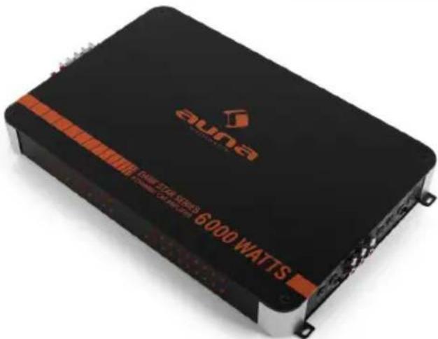
natural_image
Symbol of a trash bin with crossed lines indicating no waste, and a solid rectangle below (no text or labels)Chal-Tec UK limited Unit 6 Riverside Business Centre Brighton Road Shoreham-by-Sea BN43 6RE United Kingdom
Dear Customer,
Congratulations on purchasing this equipment. Please read this manual carefully and take care of the following hints on installation and use to avoid technical damages. Any failure caused by ignoring the items and cautions mentioned in the operation and installation instructions are not covered by our warranty and any liability.
Features
- 90W x 2 Channel/ 90W x 4 Channel/ 90W x 6 Channel
- Multi-mode connection capability for Simultaneous subwoofer & satellite speaker operation
- Adjustable subwoofer crossover frequency(30—250Hz)
• High current discrete output devices - Adjustable RCA level inputs
- Input ground isolation noise rejection circuit
Power Supply Section
- Ultra stable PWM (Pulse width modulated)
• Power supply (11\~16V)
• Thermal Protection circuit - Remote on power switching
General
- Transient noise muting
- Turn on delay
- Speaker short circuit protection
• Gold plate RCA input and terminals - Chassis mount ATC fuse protectionGeräuschreduzierung
1. Connection of Power Cord
- Since this unit deals with a high power, large current will flow and the wiring or power cord is high importance.
- Connect the red wire directly to the (+) terminal of the battery using the cord with a fuse holder supplied.
- Connect the black wire tightly to an appropriate screw on the metal part of car after removing paint for proper grounding. Be sure to use the screw not bring danger for driving.
- Proper connection will provide clear sound.
2. Connection of Remote On/Of Wire
- Connect the orange wire to a switched power cord of the car stereo to be connected to this unit will control the unit power on/off with the car stereo's
- The switched power cord may be obtained an auto antenna cord of the car stereo.
3. Connection of Booster Input (High Input)
- This unit can be connected to any car stereo with high level outputs, common or separated ground outputs.
- Separated ground car stereo connection;-connect car stereo speaker output cables to the high level input connector (+) and (-), right and left polarity.
- Common ground car stereo connection;-connect car stereo speakers negative output cable to the high level input connector to the two signs (-) and the remaining cables to (+) right and left..
4. Connection of AUX Input (Low Input)
- Connect the AUX input wires with RCA type pin jack as follows: white to L Ch pre—output of the car stereo. Red to R Ch pre—output of the car stereo.
- Before connecting the pre—output of the car stereo or other unit, confirm the impedance or sensitivity to match with this unit AUX input.
5. Input Sensitivity Control
- Adjust the input sensitivity to output of a car stereo connected.
6. Connection of Speaker (Stereo / Mono)
- Connect the speaker wires as per the following figures
2-Channel


4-Channel
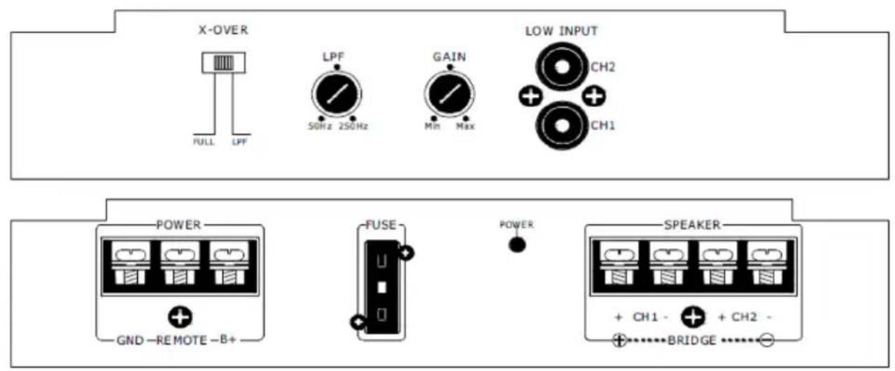
6-Channel

flowchart
graph LR
    subgraph Channel 1
        A["LPF"] --> B["X-OVER"]
        B --> C["FULL LPF"]
        C --> D["50Hz 250Hz"]
        D --> E["GAIN"]
        E --> F["MIN Max"]
        F --> G["LPF"]
        G --> H["50Hz 250Hz"]
        H --> I["GAIN"]
        I --> J["MIN Max"]
        J --> K["LPF"]
        K --> L["CHANNEL 5/6"]
        M["X-OVER"] --> N["FULL LPF"]
        O["AUDIO IN"] --> P["CH 6 CH 4 CH 2"]
        Q["X-OVER"] --> R["FULL LPF"]
        S["X-OVER"] --> T["CHANNEL 1/2"]
    end
    style Channel 1 fill:#f9f,stroke:#333
    style Channel 2 fill:#ccf,stroke:#333
    style Channel 3 fill:#cfc,stroke:#333
    style Channel 4 fill:#fcc,stroke:#333
    style Channel 5 fill:#ffc,stroke:#333
    style Channel 6 fill:#cff,stroke:#333
    style Channel 7 fill:#ffc,stroke:#333
    style Channel 8 fill:#ffc,stroke:#333
    style Channel 9 fill:#ffc,stroke:#333
    style Channel 10 fill:#ffc,stroke:#333
    style Channel 11 fill:#ffc,stroke:#333
    style Channel 12 fill:#ffc,stroke:#333
    style Channel 13 fill:#ffc,stroke:#333
    style Channel 14 fill:#ffc,stroke:#333
    style Channel 15 fill:#ffc,stroke:#333
    style Channel 16 fill:#ffc,stroke:#333
    style Channel 17 fill:#ffc,stroke:#333
    style Channel 18 fill:#ffc,stroke:#333
    style Channel 19 fill:#ffc,stroke:#333
    style Channel 20 fill:#ffc,stroke:#333
    style Channel 21 fill:#ffc,stroke:#333
    style Channel 22 fill:#ffc,stroke:#333
    style Channel 23 fill:#ffc,stroke:#333
    style Channel 24 fill:#ffc,stroke:#333
    style Channel 25 fill:#ffc,stroke:#333
    style Channel 26 fill:#ffc,stroke:#333
    style Channel 27 fill:#ffc,stroke:#333
    style Channel 28 fill:#ffc,stroke:#333
    style Channel 29 fill:#ffc,stroke:#333
    style Channel 30 fill:#ffc,stroke:#333
    style Channel 31 fill:#ffc,stroke:#333
    style Channel 32 fill:#ffc,stroke:#333
    style Channel 33 fill:#ffc,stroke:#333
    style Channel 34 fill:#ffc,stroke:#333
    style Channel 35 fill:#ffc,stroke:#333
    style Channel 36 fill:#ffc,stroke:#333
    style Channel 37 fill:#ffc,stroke:#333
    style Channel 38 fill:#ffc,stroke:#333
    style Channel 39 fill:#ffc,stroke:#333
    style Channel 40 fill:#ffc,stroke:#333
    style Channel 41 fill:#ffc,stroke:#333
    style Channel 42 fill:#ffc,stroke:#333
    style Channel 43 fill:#ffc,stroke:#333
    style Channel 44 fill:#ffc,stroke:#333
    style Channel 45 fill:#ffc,stroke:#333
    style Channel 46 fill:#ffc,stroke:#333
    style Channel 47 fill:#ffc,stroke:#333
    style Channel 48 fill:#ffc,stroke:#333
    style Channel 49 fill:#ffc,stroke:#333
    style Channel 50 fill:#ffc,stroke:#333

Note:
- Because of high power unit, approx 7,5A/15A/20A will be drained at peak power. Using the unit while the engine is stopped may totally discharge the battery. Please run the engine in using the unit.
- Because of large current flows, please use power supply cord of sufficient capacity if required. (Larger than 3mm square.)
- This unit is designed of use with the speakers 2\~16Ω impedance. The speaker must have enough capacity to accept the high power of the unit. Please carefully confirm the rating of the speaker before connection.
Wiring Operation for Stereo
2- Channel

4- Channel

flowchart
graph TD
    subgraph Left_Circuit
        A["IN"] --> B["X-OVER"]
        C["OL4"] --> B
        D["OL3"] --> B
        E["GAIN"] --> F["50Hz 250Hz"]
        G["Max"] --> F
        H["LPF"] --> F
        I["FULL"] --> F
        J["50Hz"] --> K["LPF"]
        L["250Hz"] --> K
    end
    subgraph Right_Circuit
        M["IN"] --> N["X-OVER"]
        O["OL4"] --> N
        P["GAIN"] --> Q["50Hz 250Hz"]
        R["OL3"] --> Q
        S["Max"] --> Q
        T["LPF"] --> Q
        U["FULL"] --> Q
        V["50Hz"] --> W["LPF"]
        X["250Hz"] --> W
        Y["Full"] --> W
        Z["50Hz"] --> AA["LPF"]
        AB["250Hz"] --> AA
        AC["Full"] --> AA
        AD["50Hz"] --> AE["LPF"]
        AF["250Hz"] --> AE
        AG["Full"] --> AE
        AH["50Hz"] --> AI["LPF"]
        AJ["250Hz"] --> AI
        AK["Full"] --> AI
        AL["50Hz"] --> AM["LPF"]
        AN["250Hz"] --> AM
        AO["Full"] --> AM
        AP["50Hz"] --> AQ["LPF"]
        AR["250Hz"] --> AQ
        AS["Full"] --> AQ
    end
    subgraph Right_Dire_Circuit
        AT["X-OVER"] --> AU["IN"]
        AV["X-OVER"] --> AW["OUT"]
        AX["GARSTERED"] --> AY["LOW INPUT"]
    end
6- Channel


Wiring Operation for Speakers
2- Channel

flowchart
graph TD
    A["POWER"] --> B["GND-REMOTE-B+"]
    C["FUSE"] --> D["+"]
    E["SPEAKER"] --> F["+ CH1 - + CH2 -"]
    G["TO CAB BATTERY (-)"] --> H["BLACK"]
    I["TO CAB BATTERY (-)"] --> J["ORANGE"]
    K["TO CAB BATTERY (-)"] --> L["RED"]
    M["BRIDGE"] --> N["Speaker"]
    O["Power"] --> P["+"]
    Q["Power"] --> R["+"]
    S["Power"] --> T["+"]
4- Channel

6- Channel

flowchart
graph TD
    A["Power"] --> B["GND-REMOTE-B+"]
    C["FUSE"] --> D["10A"]
    D --> E["10A"]
    F["Speaker"] --> G["CH1-"]
    F --> H["CH2-"]
    F --> I["CH3-"]
    F --> J["CH4-"]
    F --> K["BRIDGE"]
    L["Speaker"] --> M["CH5-"]
    L --> N["CH6-"]
    L --> O["BRIDGE"]
    P["Black"] --> Q["TO CAB BATTERY(-)"]
    R["Orange"] --> S["REMOTE"]
    T["Red"] --> U["TO CAB BATTERY(-)"]
    V["Speaker"] --> W["BRIDGE"]
    X["Black"] --> Y["TO CAB BATTERY(-)"]
    Z["Orange"] --> AA["REMOTE"]
    AB["Red"] --> AC["TO CAB BATTERY(-)"]
    AD["Speaker"] --> AE["BRIDGE"]
    AF["Black"] --> AG["TO CAB BATTERY(-)"]
    AH["Orange"] --> AI["REMOTE"]
    AJ["Red"] --> AK["TO CAB BATTERY(-)"]
    AL["Speaker"] --> AM["BRIDGE"]
Mounting
Please mount at your option using screws and fixtures supplied with the units
CAUTION::
- The unit itself will be heated because of its high power.
- Therefore, please leave room around the unit in mounting and while in use, and do not put things on the unit.
Specification
| Output Power 90W x 2 Channel/ 90W x 4 Channel/ 90W x 6 Channel |
| Frequency response 20Hz-20KHz at 1dB |
| Input Sensitivity High: 1.0-2.0V impedance 100 Ω |
| Signal ratio Better than 95 dB |
| Speaker impedance 4-16 Ω |
| Subwoofer Frequency adjustable 30Hz-250Hz |
| Power Supply DC 14.4V |
| Dimension 320 x 261 x 59mm |
| Accessory Screw set & spare fuse |

10R-041283
DISPOSAL CONSIDERATIONS
natural_image
Symbol of a trash bin with crossed lines and a blank rectangular base (no text or numbers)If there is a legal regulation for the disposal of electrical and electronic devices in your country, this symbol on the product or on the packaging indicates that this product must not be disposed of with household waste. Instead, it must be taken to a collection point for the recycling of electrical and electronic equipment. By disposing of it in accordance with the rules, you are protecting the environment and the health of your fellow human beings from negative consequences. For information about the recycling and disposal of this product, please contact your local authority or your household waste disposal service.
MANUFACTURER & IMPORTER (UK)
CE
Chal-Tec GmbH, Wallstrasse 16, 10179 Berlin, Germany.
UK CA
Importer for Great Britain:
Chal-Tec UK limited Unit 6 Riverside Business Centre Brighton Road Shoreham-by-Sea BN43 6RE United Kingdom

- Features
- Power Supply Section
- General
- Connection of Power Cord
- Connection of Remote On/Of Wire
- Connection of Booster Input (High Input)
- Connection of AUX Input (Low Input)
- Input Sensitivity Control
- Connection of Speaker (Stereo / Mono)
- Note:
- Wiring Operation for Stereo
- 2- Channel
- 4- Channel
- Wiring Operation for Speakers
- Mounting
- CAUTION::
- DISPOSAL CONSIDERATIONS
- MANUFACTURER & IMPORTER (UK)
Brand : Auna
Model : Dark Star 6000
Category : Car radio