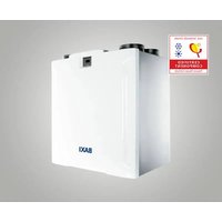
Sila RCV 400 - Fan Baxi - Free user manual and instructions
Find the device manual for free Sila RCV 400 Baxi in PDF.


| Product Type | Fan |
| Brand | Baxi |
| Model | Sila RCV 400 |
| Dimensions (H x W x D) | 400 x 400 x 200 mm |
| Weight | 5.2 kg |
| Power Supply | 220-240 V ~ 50/60 Hz |
| Power Consumption | 50 W |
| Number of Speed Settings | 3 |
| Oscillation | Yes, 90° |
| Timer | Yes, up to 2 hours |
| Remote Control | Included |
| Noise Level | 50 dB |
| Safety Features | Overheat protection, tip-over switch |
| Cleaning | Use a soft damp cloth; do not immerse in water |
| Maintenance | Clean regularly; lubricate motor annually |
| Spare Parts | Blades, motor, remote control available from Baxi |
| Repairability | Service centers available; contact Baxi support |
| General Information | Suitable for home use; stylish design |
Frequently Asked Questions - Sila RCV 400 Baxi
User questions about Sila RCV 400 Baxi
0 question about this device. Answer the ones you know or ask your own.
Ask a new question about this device
Download the instructions for your Fan in PDF format for free! Find your manual Sila RCV 400 - Baxi and take your electronic device back in hand. On this page are published all the documents necessary for the use of your device. Sila RCV 400 by Baxi.
USER MANUAL Sila RCV 400 Baxi
Residential heat recovery
Installation instructions, Functioning and Maintenance
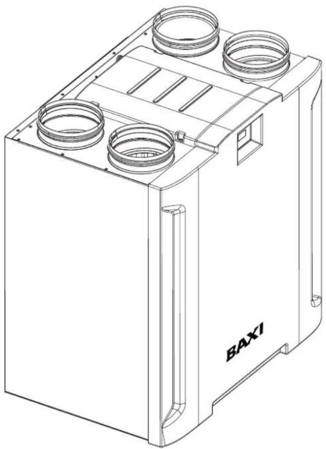
natural_image
Technical line drawing of a mechanical housing or enclosure with four circular components and mounting brackets (no text or symbols)CE
ESPAÑOL
índice
1 Información general....3
natural_image
Technical diagram of a rectangular device with four circular components and labeled dimensions F and G (no text or symbols beyond labels)| PRODUCT | A | B | C | D | E | F | G | H | I | J | K | L |
| SILA RCV 400 | 711 | 487 | 780 | 733 | 453 | 205 | 516 | 158 | 400 | 305 | 207 | 16 |
natural_image
Simple line drawing of a mechanical lever with fulcrum and weights (no text or symbols)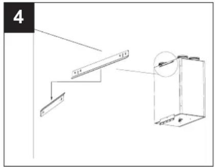

natural_image
Diagram showing a mechanical assembly with screws and a tool, no text or symbols present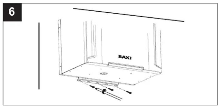
natural_image
Technical line drawing of a mechanical housing or enclosure with circular components and a central vertical panel (no text or symbols)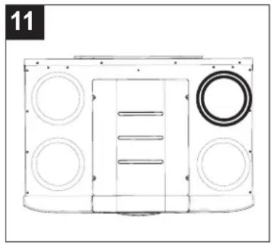
natural_image
Technical line drawing of a mechanical housing or enclosure with circular components and a central vertical bar (no text or symbols)
natural_image
Technical line drawing of a mechanical component with circular features and a central rectangular structure (no text or symbols)
natural_image
Technical line drawing of a vehicle front panel with circular components and a central vertical structure (no text or symbols)13 Funcionamiento
13.1 Motores
natural_image
Technical diagram of an electronic circuit board layout with components and connectors (no readable text or symbols)ESPAÑOL
flowchart
graph LR
    A["INSTALL\nLIFE TIME\nRESET FIL\nMBUS ID"] --> B["→"]
    B --> C["LIFE TIME\n12"]
RESET FIL
flowchart
graph LR
    A["INSTALL\nNO FROST\nPOSTHEAT\nPOSTTEMP"] --> B["→"]
    B --> C["POSTHEAT\nYES"]
POSTTEMP
flowchart
graph LR
    A["MAIN MENU\nUSE MENU\nALARM\nSETUP"] --> B["→"]
    B --> C["ALARM\nINT PROBE\nCALL\nSERVICE YES"]
flowchart
graph LR
    A["MAIN MENU\nUSE MENU\nALARM\nSETUP"] --> B["→"]
    B --> C["ALARM\nSUP PROBE\nCALL\nSERVICE YES"]
No Frost
flowchart
graph LR
    A["MAIN MENU\nUSE MENU\nALARM\nSETUP"] --> B["→"]
    B --> C["ALARM\nNO FROST WAIT\n1 HOUR"]
Setup

ESPAÑOL
PROGRAM
natural_image
Technical line drawing of a device housing with internal compartments and mounting features, shown in two views (no text or symbols)

natural_image
Diagram of a battery with arrows indicating flow or movement, showing internal components and directional arrows (no text or symbols)flowchart
graph LR
    A["Raw Material Input"] --> B["Add Box"]
    B --> C["Add Box with Outer Ring"]
    C --> D["Add Box with Inner Ring"]
    D --> E["Add Box with Outer Ring"]
    E --> F["Add Box with Inner Ring"]
    F --> G["Add Box with Outer Ring"]
    G --> H["Final Product Output"]
ESPAÑOL
15.3 Limpieza externa
natural_image
Simple line drawing of a mechanical device with a lever and base, no text or symbols present
natural_image
Technical line drawing of a staircase with an attached cabinet, no text or symbols present
natural_image
Technical diagram showing a mechanical assembly with pins and a bracket, no text or symbols present
natural_image
Technical line drawing of a mechanical housing or enclosure with circular components and a central vertical panel (no text or symbols)natural_image
Technical line drawing of a mechanical component with circular and ring features (no text or symbols)natural_image
Technical line drawing of a mechanical component with circular components and a central rectangular structure (no text or symbols)11 Esquema de funcionamento do sistema
14
13 Funcionamento
13.1 Motores
natural_image
Technical schematic of an electronic circuit board layout with components and connectors (no readable text or symbols)flowchart
graph LR
    A["INSTALL\nSETUP BYP\nLIFE TIME\nRESET FIL"] --> B["→"]
    B --> C["SETP BYP\n018"]
LIFE TIME
flowchart
graph LR
    A["INSTALL\nLIFE TIME\nRESET FIL\nMBUS ID"] --> B["→"]
    B --> C["LIFE TIME\n12"]
RESET FIL
flowchart
graph LR
    A["INSTALL\nNO FROST\nPOSTHEAT\nPOSTTEMP"] --> B["→"]
    B --> C["POSTHEAT\nYES"]
POSTTEMP
flowchart
graph LR
    A["MAIN MENU"] --> B["ALARM SETUP INFO"]
    B --> C["→"]
    C --> D["ALARM CHECK OR CLEAR FILTER"]
flowchart
graph LR
    A["MAIN MENU\nUSE MENU\nALARM\nSETUP"] --> B["→"]
    B --> C["ALARM\nINT PROBE\nCALL\nSERVICE YES"]
flowchart
graph LR
    A["MAIN MENU\nUSE MENU\nALARM\nSETUP"] --> B["→"]
    B --> C["ALARM\nNO FROST\WAIT\n1 HOUR"]
PORTUGUES
Setup
natural_image
Technical line drawing of a mechanical device with internal components and directional arrows indicating assembly (no text or symbols)
1 General informations....57
1.1 Description of the symbols....57
1.1.1 Obligation....57
1.1.2 Prohibition....57
1.1.3 Danger 57
1.2 Purpose of the manual....57
2 Product description 58
3 Structure and equipment....58
4 Compliance....59
5 Safety/Warnings 59
6 Technical data....60
7 Fan performance graph....61
8 Dimensions....61
9 General warnings for the installer 62
10Installation 63
10.1 Assembly....63
10.2 Connecting the condensate drain tube 63
10.3Piping connection....64
10.4Stale air supply toward outside 64
10.5Fresh air from outside 64
10.6Stale air exhaust from room (extract)....64
10.7 Fresh air supply to room 64
11 System operating diagram....65
12Electrical connections....66
13Operation 67
13.1 Motors 67
13.2 Filters: 67
13.3Bypass 67
13.4 Automatic defrost 67
13.5USB outlet 67
13.6 Holiday 68
13.7Post-ventilation....68
13.8Program 68
14Use....69
14.1 General 69
14.2 Meaning of icons buttons in the touch area: 69
14.3CONTROL PANEL FUNCTIONS 70
14.4 Main menu 71
14.4.1 Installer functions (password 023)....71
14.4.2User functions (password 013)....76
15 Maintenance and cleaning 81
15.1 Filters: 81
15.2 Heat exchanger 81
15.3External cleaning 82
16 Disposal 82
1 General informations
1.1 Description of the symbols
1.1.1 Obligation.

GENERIC OBLIGATION

READING INSTRUCTIONS IS MANDATORY

1.2 Purpose of the manual
This manual contains information on the use and maintenance of the appliance and provides useful information for the correct use of the appliance.

OBLIGATION
Before installing and using the appliance, read the warnings in this manual carefully
BAXI cannot assume any responsibility for damage to property or personal injury resulting from failure to abide by the instructions given in this booklet. Following these instructions will ensure a long service life and overall electrical and mechanical reliability. Keep this instruction booklet in a safe place. Do not make modifications to this manual.
Before installing and using your product, read these instructions carefully.
BAXI cannot assume any responsibility for damage to property or personal injury resulting from failure to abide by the instructions given in this booklet. Following these instructions will ensure a long service life and overall electrical and mechanical reliability. Keep this instruction booklet in a safe place.
2 Product description
Vort HR 450 Avel D (hereinafter “device”) is a heat recovery unit for residential use characterised by its high thermal exchange efficiency, low consumption and small size. The device is controlled by an advanced electronic management system and is equipped with fan motors with EC brushless motors.
A heat exchanger is set inside the device. The exchanger guarantees high thermal exchange efficiency. The device is equipped with an automatic bypass function and incorporated antifreeze protection.
(See "Operation" and "Use" for a more detailed description of the various functions).
Before installing and/or using the equipment, read this instructions manual carefully, in particular the paragraph on "Safety".
3 Structure and equipment
- The main components of the device can be summarised as follows (fig.1):
- ABS panel (1)
- outer casing and front cover (2) in painted sheet steel; the devices for connecting the suction/supply pipes and the electrical connection box are integrated in the casing; the casing also encloses the internal components and the heat exchanger;
- fixing rails (3): two upper ones, one of which to be fixed to the wall, and one lower: these allow for wall mounting;
- internal conveyors in PPE (expanded polypropylene) (4), which implement the distribution of air flows maximising thermal insulation and minimising losses;
- counter cross flow heat exchanger (5) in plastic resin, whose particular morphology guarantees a very high heat exchange efficiency;
• G4 retention grade filters (6); G4 retention grade (bypass) filter (7);
• brushless motors (8) combined with centrifugal impellers; - user interface with LCD display (9);
• 4 temperature sensors (10):
'-Internal air
'-External air
'-Exhaust air
'-Supply air
• filter replacement warning timer
• output for connection to a pre-heater (No frost operation)
• output for connection to a post-heater
1

4 Compliance
- This appliance can be used by children aged from 8 years and above and persons with reduced physical, sensory or mental capabilities or lack of experience and knowledge if they have been given supervision or instruction concerning use of the appliance in a safe way and understand the hazards involved. Children shall not play with the appliance. Cleaning and user maintenance shall not be made by children without supervision.
- These appliances are designed for use in residential and commercial properties.
- The appliance must be installed by a professionally qualified electrician only.
- Ensure that the electrical system to which the appliance is connected complies with applicable standards.
- An omnipolar switch with a contact opening distance of 3 mm or higher should be provided for installation, enabling complete disconnection under overvoltage category III conditions.
- Products equipped with single-phase wiring (M) engines ALWAYS require connection to 220-240V (or only 230V where required) single-phase lines. Any kind of modification shall be considered as product tampering and shall nullify the relative Warranty.
- It is not necessary to make any specific adjustments as the appliances operate at nominal frequencies without a preliminary setting.
5 Safety/Warnings

OBLIGATION
- After removing the appliance from its packaging, ensure that it is complete and undamaged. If in doubt contact an authorised BAXI service centre. Do not leave packaging within the reach of children or differently able persons.
- Store the appliance out of the reach of children and disabled persons if you decide to disconnect it from the power supply and use it no more.

OBLIGATION
- In the event that the appliance malfunctions or develops a fault, contact BAXI* immediately. Ensure that only genuine original BAXI spares are used for repairs.
- Check that the electrical power supply/socket provides the maximum electrical power required by the appliance. If this is not the case, arrange for a qualified electrician to make the necessary modifications.

OBLIGATION
The electrical specifications correspond to the ones on the data label

PROHIBITION
- Do not use this appliance for functions other than those described in this booklet.
- Do not make modifications of any kind to this appliance

DANGER
- Certain fundamental rules must be observed when using any electrical appliance:
– never touch appliances with wet or damp hands;
– never touch appliances while barefoot;
– do not allow the unit to be operated by unsupervised children or disabled persons.
- In order to avoid any danger of accidental reset of the thermal breaker device, devices must not be powered by an external switch device such as a timer, or must not be connected to a circuit that is regularly powered or disconnected
- In case of damage to the power cable contact an authorized BAXI service center to have it replaced to prevent any risk.

OBLIGATION
In the event that the appliance is dropped or suffers a heavy blow, have it checked immediately by BAXI.
6 Technical data
| Model | SILA RCV 400 |
| Energy specific consumption SEC - (average) [kWh/m2a] | -37,0 |
| Energy specific consumption SEC - (cold) [kWh/m2a] | -75,0 |
| Energy specific consumption SEC - (warm) [kWh/m2a] | -12,0 |
| Declared ventilation type | UVR-B |
| Drive type (VM - VSD - N/A) | VSD |
| Typology of heating recovery system HRS | Heat recovery |
| Thermal efficiency of heating recovery [%] | 88 |
| Max flow rate (Qmax) [m3/h] | 400,0 |
| Power consumption of motorfans at Qmax [W] | 285,5 |
| Sound Power level LWA (at reference flow rate) [dB(A)] | 47 |
| Reference flow rate [m3/h] | 280,0 |
| Difference of reference pressure [Pa] | 50 |
| SPI (specific power input) [W/(m3/h)] | 0,384 |
| Control factor CTRL | 0,85 |
| Control typology | Amb. Central. |
| Maximum internal leakage rates (only for bidir.units) [%] | 0,3 |
| Maximum external leakage rates [%] | 0,6 |
| Airflow sensitivity to pressure variations at ±20 Pa | N.A. |
| Indoor/outdoor air tightness [m3/h] | N.A. |
| Mixing rate | N.A. |
| Position and description of visual filter warning | N.A. |
| Annual electricity consumption (AEC) [kWh electricity/y] | 393 |
| AHSaverage Annual heating saved[kWh primary energy/a] | 4576 |
| AHScold Annual heating saved[kWh primary energy/a] | 8951 |
| AHSwarm Annual heating saved[kWh primary energy/a] | 2069 |
| Energy classification | A |

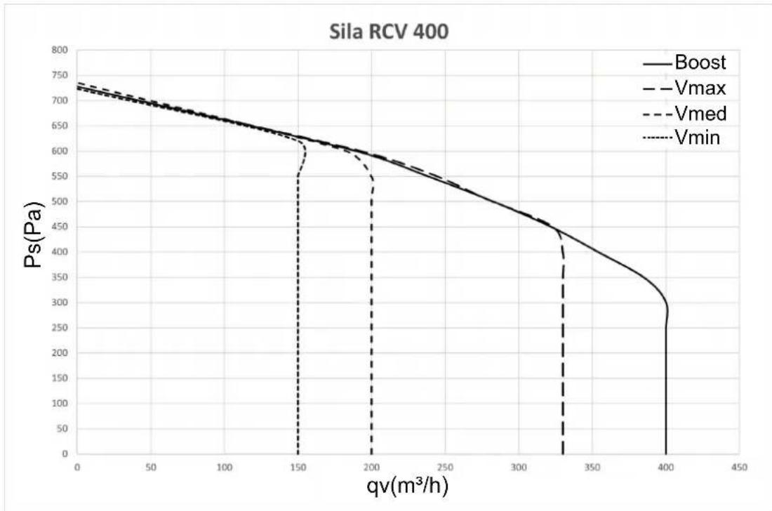
7 Fan performance graph
line
| qv(m³/h) | Boost | Vmax | Vmed | Vmin | | -------- | ----- | ---- | ---- | ---- | | 0 | 730 | 725 | 720 | 715 | | 50 | 700 | 695 | 690 | 685 | | 100 | 660 | 655 | 650 | 645 | | 150 | 620 | 615 | 610 | 605 | | 200 | 580 | 575 | 570 | 565 | | 250 | 540 | 535 | 530 | 525 | | 300 | 480 | 475 | 470 | 465 | | 350 | 420 | 415 | 410 | 405 | | 400 | 300 | 295 | 290 | 285 | | 450 | 0 | 0 | 0 | 0 |8 Dimensions

| PRODUCT | A | B | C | D | E | F | G | H | I | J | K | L |
| SILA RCV 400 | 711 | 487 | 780 | 733 | 453 | 205 | 516 | 158 | 400 | 305 | 207 | 16 |
9 General warnings for the installer

DANGER
- Switch off the main switch on the system when: a malfunction is detected, you decide to perform external cleaning maintenance, you decide not to use the device for short or long periods.
- The appliance must be installed in such a way as to ensure that under normal operating conditions, no one can come into contact with any moving parts or live electrical components.
- The device must discharge directly outside in a single allocated duct.
- The device cannot be used as an activator for water heaters, stoves, etc. nor should it discharge into the hot air ducts of said devices.
- Maximum operating temperature: 45°C
10 Installation
10.1 Assembly
The device is equipped with three rails to be used for wall mounting. One of the two upper rails is pre-assembled on the device (fig. 2 ÷ 6).
If it necessary to fix the product to the wall, be sure to use the brackets and screws to fix it.
ATTENTION: Before fixing the support brackets, make sure to maintain the distance for the connection of the ventilation pipes and the condensate drain from the ceiling and floor as shown in fig. 2.


natural_image
Technical line drawing of a mechanical assembly with a lever and base (no text or symbols)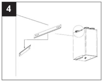


10.2 Connecting the condensate drain tube
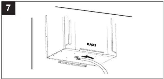
The connection point is located on the bottom of the device. The condensate drain must be implemented by connecting the supplied flexible hose to the condensate drain connection. A siphon must be made with the tube (fig. 7,8) to prevent the formation of air bubbles.

ENGLISH
10.3 Piping connection
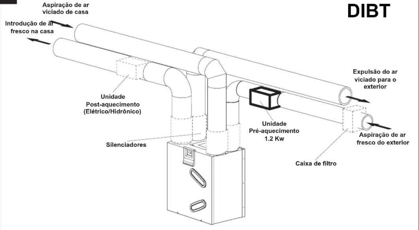
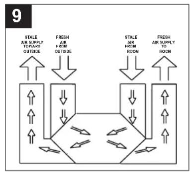
The device fittings have a nominal diameter of 160 mm. Rigid or flexible pipes can be connected to the device inlets. Below is an illustration of each connection with a specification also of the directions of origin and supply of the relative air flow (fig.9). ATTENTION: For passivhaus compliant systems, it will be necessary to install silencers on all 4 air vents.
10.4 Stale air supply toward outside
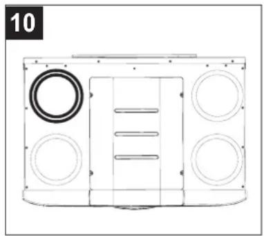
This inlet is used to expel stale air, which has already been treated in the heat exchanger, to the outside. The duct to which the exhaust must be connected must be thermally insulated (to avoid the formation of condensation inside or outside its parts), and provided with devices to dampen any vibrations. If the exhaust takes place from the roof, there must be a suitable device present to prevent the formation of condensation and the entry of rainwater (fig.10).
10.5 Fresh air from outside
This inlet is used for the entry of fresh air from the outside. The relative duct must be thermally insulated and provided with devices able to dampen any vibrations. If air inlet occurs from the roof, the use of a suitable device is required to prevent the formation of condensate and the entry of rain water. (fig. 11)
10.6 Stale air exhaust from room (extract)
This inlet is used to convey stale air extracted from inside the house into the device. The duct must be thermally insulated. (fig. 12)
10.7 Fresh air supply to room
This inlet is used to pump fresh outside air, which has already been treated in the heat exchanger, into the house (fig. 13).
flowchart
graph TD
    A["Stale Air Supply TOWARD OUTSIDE"] --> B["FRESH AIR FROM OUTSIDE"]
    B --> C["Stale Air FROM ROOM"]
    C --> D["FRESH AIR SUPPLY TO ROOM"]
    D --> E["Stale Air Supply TOWARD OUTSIDE"]
    E --> F["FRESH AIR FROM OUTSIDE"]
    F --> G["Stale Air Supply TOWARD OUTSIDE"]
    G --> H["FRESH AIR FROM ROOM"]
    H --> I["Stale Air Supply TOWARD OUTSIDE"]
    I --> J["FRESH AIR FROM OUTSIDE"]
    J --> K["Stale Air Supply TOWARD OUTSIDE"]
    K --> L["FRESH AIR FROM ROOM"]
    L --> M["Stale Air Supply TOWARD OUTSIDE"]
    M --> N["FRESH AIR FROM OUTSIDE"]
    N --> O["Stale Air Supply TOWARD OUTSIDE"]
    O --> P["FRESH AIR FROM OUTSIDE"]
    P --> Q["Stale Air Supply TOWARD OUTSIDE"]
    Q --> R["FRESH AIR FROM OUTSIDE"]
    R --> S["Stale Air Supply TOWARD OUTSIDE"]
    S --> T["FRESH AIR FROM OUTSIDE"]
    T --> U["Stale Air Supply TOWARD OUTSIDE"]
    U --> V["FRESH AIR FROM OUTSIDE"]
    V --> W["Stale Air Supply TOWARD OUTSIDE"]
    W --> X["FRESH AIR FROM OUTSIDE"]
    X --> Y["Stale Air Supply TOWARD OUTSIDE"]
    Y --> Z["FRESH AIR FROM OUTSIDE"]
    Z --> AA["Stale Air Supply TOWARD OUTSIDE"]
    AA --> AB["FRESH AIR FROM OUTSIDE"]
    AB --> AC["Stale Air Supply TOWARD OUTSIDE"]
    AC --> AD["FRESH AIR FROM OUTSIDE"]
    AD --> AE["Stale Air Supply TOWARD OUTSIDE"]
    AE --> AF["FRESH AIR FROM OUTSIDE"]
    AF --> AG["Stale Air Supply TOWARD OUTSIDE"]
    AG --> AH["FRESH AIR FROM OUTSIDE"]
    AH --> AI["Stale Air Supply TOWARD OUTSIDE"]
    AI --> AJ["FRESH AIR FROM OUTSIDE"]
    AJ --> AK["Stale Air Supply TOWARD OUTSIDE"]
    AK --> AL["FRESH AIR FROM OUTSIDE"]
    AL --> AM["Stale Air Supply TOWARD OUTSIDE"]
    AM --> AN["FRESH AIR FROM OUTSIDE"]
    AN --> AO["Stale Air Supply TOWARD OUTSIDE"]
    AO --> AP["FRESH AIR FROM OUTSIDE"]
    AP --> AQ["Stale Air Supply TOWARD OUTSIDE"]
    AQ --> AR["FRESH AIR FROM OUTSIDE"]
    AR --> AS["Stale Air Supply TOWARD OUTSIDE"]
    AS --> AT["FRESH AIR FROM OUTSIDE"]
    AT --> AU["FRESH AIR FROM OUTSIDE"]
    AU --> AV["Stale Air Supply TOWARD OUTSIDE"]
    AV --> AW["FRESH AIR FROM OUTSIDE"]
    AW --> AX["Stale Air Supply TOWARD OUTSIDE"]
    AX --> AY["FRESH AIR FROM OUTSIDE"]
    AY --> AZ["Stale Air Supply TOWARD OUTSIDE"]
    AZ --> BA["FRESH AIR FROM OUTSIDE"]
    BA --> BB["Stale Air Supply TOWARD OUTSIDE"]
    BB --> BC["FRESH AIR FROM OUTSIDE"]
    BC --> BD["Stale Air Supply TOWARD OUTSIDE"]
    BD --> BE["FRESH AIR FROM OUTSIDE"]
    BE --> BF["Stale Air Supply TOWARD OUTSIDE"]
    BF --> BG["FRESH AIR FROM OUTSIDE"]
    BG --> BH["Stale Air Supply TOWARD OUTSIDE"]
    BH --> BI["FRESH AIR FROM OUTSIDE"]
    BI --> BJ["Stale Air Supply TOWARD OUTSIDE"]
    BJ --> BK["FRESH AIR FROM OUTSIDE"]
    BK --> BL["Stale Air Supply TOWARD OUTSIDE"]
    BL --> BM["FRESH AIR FROM OUTSIDE"]
    BM --> BN["FRESH AIR FROM OUTSIDE"]
    BN --> BO["FRESH AIR FROM OUTSIDE"]
    BO --> BP["FRESH AIR FROM OUTSIDE"]
    BP --> BQ["FRESH AIR FROM OUTSIDE"]
    BQ --> BR["FRESH AIR FROM OUTSIDE"]
natural_image
Technical line drawing of a mechanical housing or enclosure with circular components and a central vertical panel (no text or symbols)
natural_image
Technical line drawing of a mechanical housing or enclosure with circular components and a central vertical element (no text or symbols)
natural_image
Technical line drawing of a mechanical component with circular and ring features (no text or symbols)
natural_image
Technical line drawing of a mechanical component with circular and rectangular features (no text or symbols)11 System operating diagram
14

15

12 Electrical connections

flowchart
graph TD
    subgraph MAINS
        A["PE"] --> B["GNYE"]
        C["L"] --> D["BN"]
        E["N"] --> F["BU"]
        G["220-240V ~50-60 Hz"] --> H["PREH"]
        I["220-240V ~50-60 Hz"] --> J["POSTH"]
        K["3220-240V ~50-60 Hz"] --> L["BOOST"]
        M["220-240V ~50-60 Hz"] --> N["HMI"]
        O["4220-240V ~50-60 Hz"] --> P["MODBUS"]
    end

    subgraph HMI
        Q["BK"] --> R["GND"]
        S["BK"] --> T["VCC"]
        U["BK"] --> V["A"]
        W["BK"] --> X["B"]
        Y["BK"] --> Z["GND"]
        AA["BK"] --> AB["A"]
        AC["BK"] --> AD["B"]
        AE["BK"] --> AF["GND"]
    end

    subgraph MODBUS
        AG["1 Main 2 poles switch"]
        AH["2 Preheater (remote 220-240Vac relay coil)"]
        AI["3 Postheater (remote 220-240Vac relay coil)"]
        AJ["4 Dry contact (remote switch / relay)"]
        AK["5 Remote HMI Slave"]
        AL["6 Remote Modbus Master Unit - RS485"]
• The power cord must be PVC sheathed cord (model 60227 IEC 53 (RVV)), meet the requirements of GB/T 5023.5-2008/IEC 60227-5:2003, with CCC certificate for chinese market).
- The three power cable conductors must have a nominal cross-section of no less than 0.75 mm^2 and a yellow-green core connected to the earthing terminal of the device.
- To connect the HMI remote display to the machine, use cables with a section between 0.35 ~mm^2 and 2.5 ~mm^2 . Max length 80 ~m . Given that the display connection cable should be kept separate or away from the power cables, if there are problems of electromagnetic interference from other devices installed in the environment (which produce malfunction of the display), it is recommended to use shielded cables.
- To connect the pre-heater and post-heater, use cables with a minimum section of 0.5 ~mm^2 .
17

13 Operation
13.1 Motors
The unit is equipped with two brushless motors designed to ensure very low fuel consumption thanks to their very high efficiency. They are driven by two centrifugal fans that extract spoiled energy, moist air from the utility rooms (kitchens, bathrooms, laundry rooms, etc.) and introduce fresh outside air into inhabited rooms (living rooms, dining rooms, bedrooms, etc.
13.2 Filters:
Three G4 filters housed inside the delivery and extraction channels and on the bypass safeguard the device from impurities contained in the exhausted air and prevent the introduction of polluted air into the serviced rooms.
Filter occlusion conditions can be monitored by removing the components in question from their housing.
Replace standard filter G4 housed in the fresh air inlet channel with optional filter M5 to ensure higher filtering capacities. For Passivhaus compliant systems it will be necessary to replace the G4 filter housed in the fresh air intake channel and in the bypass channel with F7 filters Cod.(21624,21626).
13.3 Bypass
This type of operation is activated automatically or can be selected by the user, and is useful to ventilate apartments without heat transfer.
The opening of the bypass valve allows direct entry of outside air, preventing passage via the heat exchanger. The flow of air exhausted from the house instead continues to pass through the exchanger.
“By-Pass air Temperature” represent the “Desidered air temperature”: according to this, the Appliance activates/deactivates the bypass valve. User can select the “By-Pass air Temperature” into a range of temperatures from 15°C to 30°C. The preset “By-Pass air Temperature” value is 18°C (default).
NOTE: Automatic "Bypass" operation is deactivated when:
- The outdoor air temperature is lower than 15^ C;
- The "No Frost" function is active
13.4 Automatic defrost
The “No frost” function activates automatically when the device detects outside air temperature that is too low for a certain amount of time. When “No Frost” mode is active:
- the message "No Frost" will appear on the display
- the user cannot change Fan speed
- the "Programming" function is disabled
The main purpose of the “No Frost” function is to avoid damage to the device due to too low temperatures. In support of this function, a pre-heater can be installed on the fresh air intake channel from the outside, and a post-heater on the fresh air supply channel in the home.
When the message “Alarm!” and “Lock!” appears on the display: it represents a “no-frost timeout”. This means that “No-Frost” procedure has proved insufficient and the appliance goes into protected mode for one hour, with the motors off, following which it will restart automatically.
NOTE: Re-activation of the device is automatic and does not require any operations by the user.
For Passivhaus compliant systems it will be necessary to install a preheater on the suction channel from the outside
13.5 USB outlet
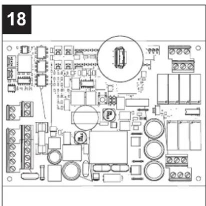
The USB outlet can be accessed on the circuit board (fig.18).
Procedure for software upgrade via USB (carried out by the Installer):
-
Copy the file "UECB_FW_UPGRADE.BIN" on a USB pen drive without renaming it
-
Disconnect the remote HMI, if installed
-
Turn off power to the machine
-
Open the upper door and insert the USB pen drive in the machine
-
Reconnect the HRU to the electrical grid
-
Wait about 30 sec – 1 minute: the LED symbol √
-
At the end of the process the HRU will go back to normal functioning.
-
Enter into the USE MENU with password 23 from the local HMI display on the machine
-
Change parameter "MBUD ID" so that it is different from 1 and different from that of the remote display: for example, enter the number 2 and press √
-
Disconnect the HRU from the electrical grid
ENGLISH
- Connect the other HMI remote control
- Reconnect the HRU to the electrical grid
- Wait about 30 sec – 1 minute: the LED symbol √
- At the end of the process the HRU will go back to normal functioning.
- Enter into the USE MENU with password 23 from the local HMI display on the machine
- Change parameter "MBUD ID" so that it is different from 1 and different from that of the remote display: for example, enter the number 2 and press √
- End
13.6 Holiday
Special mode of operation: manually enabled and useful if the user leaves the room for a longer period of time. Operation includes:
- fixed "30% less than the Minimum" speed (no other speeds, no OFF equipment);
- environment sensors not enabled (remote inputs not activated);
- bypass always closed.
NOTE: Activating the Mode "Holiday" will be deactivate other product functionings/selections.
To re-activate other product functionings/selections, need to deactivate the Mode "Holiday" before.
13.7 Post-ventilation
This kind of function is automatically activate after:
-
every time Pre-Heater is turned off (if Pre-Heater installed): both motor-fans active (about 3 minutes) to avoid overheating
-
every time you turn the Appliance off: indoor air is extracted at the max speed (about 2 minutes) to avoid condensate presence on the heat exchanger.
This is a normal system procedure and should not be perceived as a malfunction.
13.8 Program
Special mode of operation: manually enabled and allows the user to program weekly air speeds. In fact, it allows you to assign up to 6 time bands with different speeds, including stopping the equipment. When the function is active, the message "Progr." Appears on the display: see "Home Page" in the "Control panel functions" section. However, the speeds can be manually changed even at specified intervals:
in this case the word "Prg" will flash for 30 minutes and after it will go back to the setted speed
of the weekly time band, If in this 30 min any other function will change the speed, this 30 min timer
will go back to 0. For more details on setting the time slots and dates, see “PRG Crono” in the “Control panel functions” section. For details on how to activate / deactivate the function, see “Activating / deactivating Program” in the “Control panel functions” section.
14 Use
Appliance is automatically managed by an electronic control system. Appliance can automatically choose the most suitable operating mode, depending on the outside temperature.
When the appliance is switched on, both motors will run at a really slow speed for 3 minutes to allow repositioning of the by-pass valve. After, motors will start up again. NOTE: this is a normal system procedure and should not be perceived as a malfunction.
14.1 General
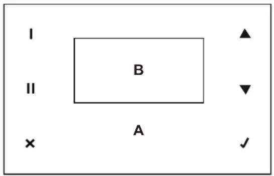
All functions can be controlled via the on-board control panel equipped with touch screen:
A: touch area
B: display
14.2 Meaning of icons buttons in the touch area:

- date/time (last line of the display) and Prog/Man display;
- T Ext, T Int, T Exh, T Sup display (last two lines of the display);
- Exit without saving and return to the previous page
- Speed increase (OFF, 1, 2, 3, Boost) either moving the cursor to the line above or increasing the value;
- Speed decrease either moving the cursor to the line below or decreasing the value;
- Confirmation of the current choice and go to the next page with saving of current data.
ENGLISH
14.3 CONTROL PANEL FUNCTIONS

Upon start-up, the display shows the BAXI logo for about 10 seconds and then the set operating speed before the last shut-down.
Note: In general, in the absence of user input, after two minutes the display will return to the logo screen without saving any changes. In this case, press √to reactivate the home screen.
In this phase, you can immediately increase the speed to the maximum value (OFF, 1, 2, 3, BOOST) via the button ▲ (▼) (to decrease from BOOST, 3, 2, 1, OFF).


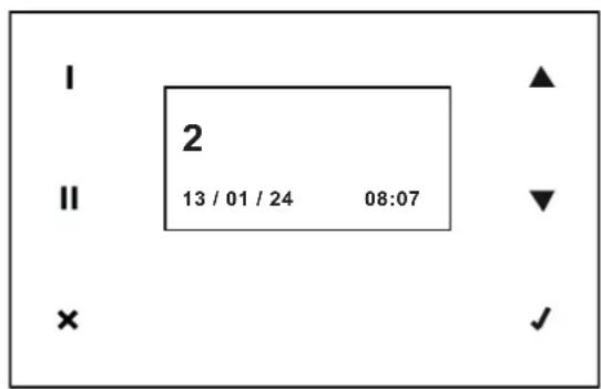
You can change the type of data shown on the bottom of the display by using the buttons and II
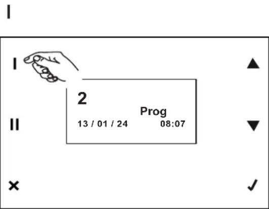

Date/time and Prog if weekly programming is active and Man if speed was changed manually during weekly programming;
Temperatures: External, Internal, Exhaust, Supply
All other functions can be reached from the main menu. The main menu can be displayed by pressing √ on the home screen.

flowchart
graph LR
    A["State 1"] --> B["Main Menu"]
    C["State 2"] --> D["USE MENU"]
    E["State 3"] --> F["ALARM"]
    G["State 4"] --> H["SETUP"]
    I["State 5"] --> J["INFO"]
14.4 Main menu
Use menu
With this option and by entering the password on the next screen, you can access installer and user settings.
Installer settings: password: 023
User settings: password: 013

flowchart
graph LR
    A["MAIN MENU\nUSE MENU\nALARM\nSETUP"] --> B["→"]
    B --> C["PASSWORD\n000"]
14.4.1 Installer functions (password 023)
The installer menu offers the following options

ENGLISH
SET UP BYPASS
This is the setpoint temperature for bypass. The editable default value is 18^ C.

flowchart
graph LR
    A["INSTALL<br>SETUP BYP<br>LIFE TIME<br>RESET FIL"] --> B["→"]
    B --> C["SETP BYP<br>018"]
LIFE TIME
The filter duration value expressed in months. The default value is 3 and can be changed to 6 and 12.
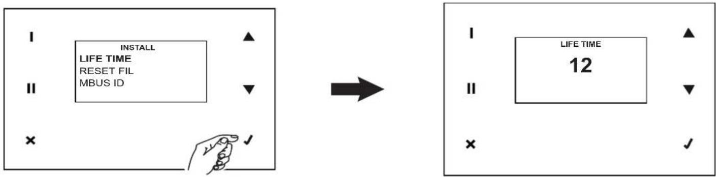
flowchart
graph LR
    A["INSTALL\nLIFE TIME\nRESET FIL\nMBUS ID"] --> B["→"]
    B --> C["LIFE TIME\n12"]
RESET FIL
This is the variable for dirty filter counter reset. The default value is NO. It can be set to YES in the case of filter replacement (or however when desired)

flowchart
graph LR
    A["INSTALL"] --> B["RESET FIL"]
    B --> C["MBUS ID"]
    B --> D["SPEED"]
    E["RESET FIL"] --> F["YES"]
MBUS ID
In the presence of another HMI user interface installed in remote, you can configure an address other than that set by default which is "160".

flowchart
graph LR
    A["INSTALL MBUS ID SPEED LANGUAGE"] --> B["→"]
    B --> C["MBUS ID 160"]
SPEED
Motor speed can be adjusted depending on the system flow rates, selecting:
VSUP=Fresh air intake from outside (see Fig. 13); VEXH=Stale air outlet to outside (see Fig.10)
Default configurations are
VSUP VEXH
VSUP1 35% VEXH1 35%
VSUP2 50% VEXH2 50%
VSUP3 83% VEXH3 83%
VSUPB 100% VEXHB 100%

flowchart
graph LR
    A["INSTALL<br>SPEED<br>LANGUAGE<br>NO FROST"] --> B["→"]
    B --> C["SPEED<br>VSUP1<br>VEXH1<br>VSUP2<br>VEXH2<br>VSUP3<br>VEXH3<br>VSUPB<br>VEXHB"]
LANGUAGE
It is the variable that defines the language of the panel texts. The default, editable value is: ENG.

flowchart
graph LR
    A["INSTALL LANGUAGE NO FROST POSTHEAT"] --> B["→"]
    B --> C["LANGUAGE ENG"]
ENGLISH
NO FROST
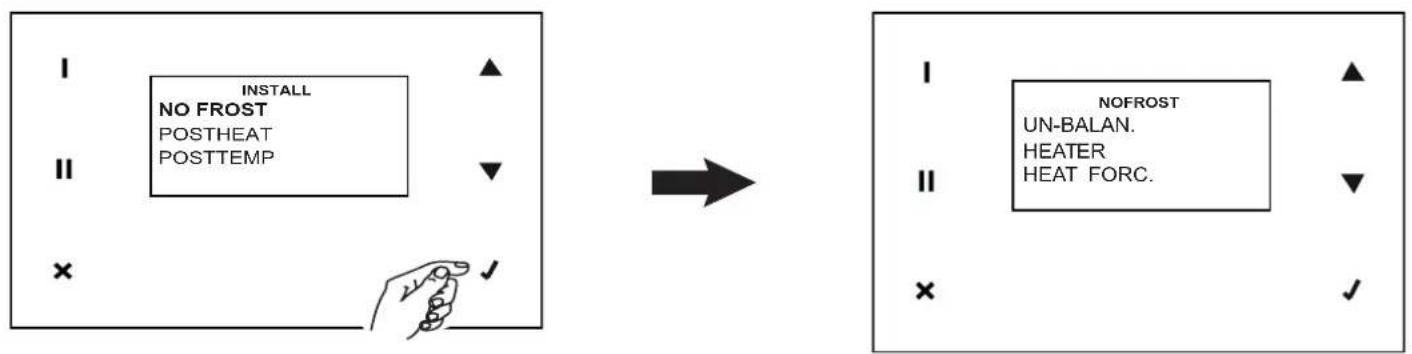
This is the variable that defines the possible strategies for NO FROST operation. The possible values are:
UN-BALAN.: flow unbalancing; note: this option must be deactivated in order for the appliance to comply with standard HEATER: pre-heater; note: this option must be activated in order for the appliance to comply with standard PASSIVHAUS HEAT FORC.: in the case that the pre-heater strategy is activated, this permits the installer to control pre-heater operation, switching it on for 15 s
Possible "No Frost" functions:
UN-BALAN: Not enabled / Enable
HEATER: Not enabled / Enable
flowchart
graph LR
    A["INSTALL\nNO FROST\nPOSTHEAT\nPOSTTEMP"] --> B["→"]
    B --> C["NOFROST\nUN-BALAN.\nHEATER\nHEAT FORC."]
POSTHEAT
The variable that controls activation of the post-heater, if present. The editable default value is: NO.

flowchart
graph LR
    A["INSTALL\nNO FROST\nPOSTHEAT\nPOSTTEMP"] --> B["→"]
    B --> C["POSTHEAT\nYES"]
POSTTEMP
The variable that defines the threshold temperature value, over which the post-heater switches on, if present. The editable default value is: 16°C.

flowchart
graph LR
    A["INSTALL\nNO FROST\nPOSTHEAT\nPOSTTEMP"] --> B["POSTHEAT\n16"]
    style A fill:#f9f,stroke:#333
    style B fill:#ccf,stroke:#333
COM ADD
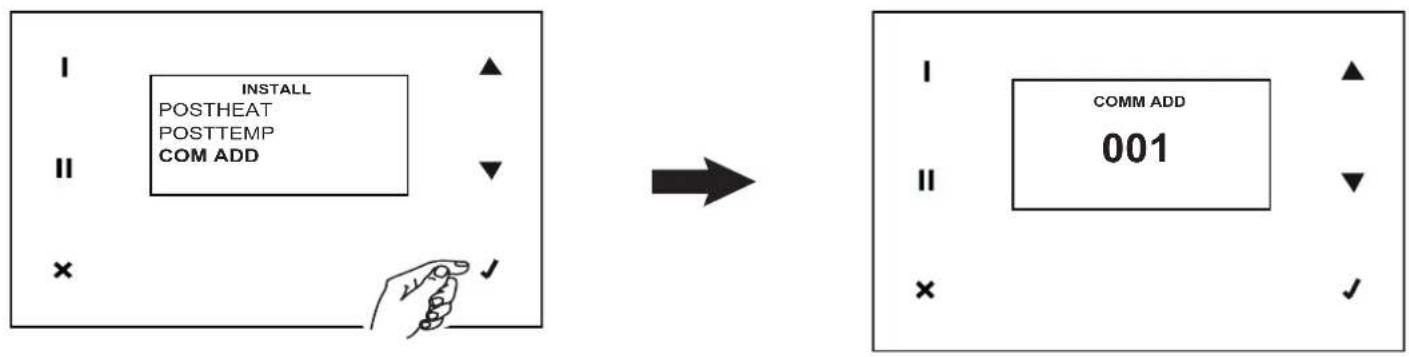
This variable defines the modbus address Slave. The default value is 1 and can be modified from 001 to 254
flowchart
graph LR
    A["INSTALL POSTHEAT POSTTEMP COM ADD"] --> B["→"]
    B --> C["COMM ADD 001"]
    style A fill:#f9f,stroke:#333
    style C fill:#bbf,stroke:#333
COM PAR
This variable defines the Baud Rate modbus Slave. The default value is 9600 and can be modified to 19200
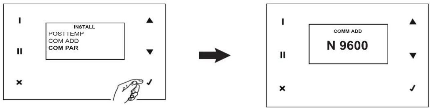
flowchart
graph LR
    A["INSTALL POSTTEMP COM ADD COM PAR"] --> B["→"]
    B --> C["COMM ADD N 9600"]
    style A fill:#f9f,stroke:#333
    style C fill:#bbf,stroke:#333
ENGLISH
14.4.2 User functions (password 013)
The user menu offers the following options: (for which you can select "YES/NO").

HOLIDAY
- YES: the fans operate at a speed of 30% below minimum.
ACT PROG
- Enable weekly programming
Alarm
This option allows you to manage all possible alarm messages. Multiple errors must be managed one by one, starting from the first one that occurred. In these situations, an intermittent "Alarm!" signal will be emitted on the home screen or intermittent messages "Alarm!", "Block!" and "OFF" will be displayed in the event of locking errors.
In all cases, you can switch on the ALARM menu to view the necessary actions and reset errors. The various situations that generate alarm signals are described below.
Filters:
When the pre-set time period has elapsed, a pre-alarm is displayed and a filter check/cleaning is required, if the filters are replaced during the pre-alarm, the counter must be reset by accessing the specific function in the installer menu.

flowchart
graph LR
    A["MAIN MENU"] --> B["ALARM SETUP INFO"]
    B --> C["→"]
    C --> D["ALARM CHECK OR CLEAR FILTER"]
When the pre-set time period has elapsed, an alarm is displayed and filter replacement is required. To replace the filters (see "Maintenance and Cleaning"), after replacing them it will be possible to reset the error and the counter.
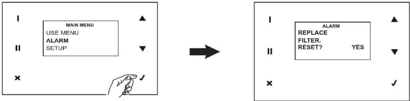
flowchart
graph LR
    A["MAIN MENU\nUSE MENU\nALARM\nSETUP"] --> B["→"]
    B --> C["ALARM\nREPLACE\nFILTER.\nRESET? YES"]
    C --> D["✓"]
Note: the counter can also be reset at any time by accessing the corresponding function in the Installer Menu
T ext probe
A fault on the external temperature sensor generates this signal. After having resolved the problem (through Technical Service intervention), you can reset the error (answer "YES" for "CALL SERVICE").
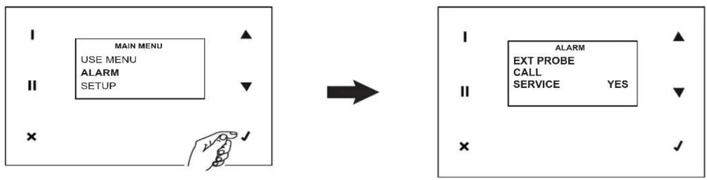
flowchart
graph LR
    A["MAIN MENU\nUSE MENU\nALARM\nSETUP"] --> B["→"]
    B --> C["ALARM\nEXT PROBE\nCALL\nSERVICE YES"]
Note: the system does not automatically call Technical Service
T int probe
A fault on the internal temperature sensor generates this signal. After having resolved the problem (through Technical Service intervention), you can reset the error (answer "YES" for "CALL SERVICE").

flowchart
graph LR
    A["MAIN MENU\nUSE MENU\nALARM\nSETUP"] --> B["→"]
    B --> C["ALARM\nINT PROBE\nCALL\nSERVICE YES"]
Note: the system does not automatically call Technical Service
Texh probe
A fault on the exhaust air temperature sensor generates this signal. After having resolved the problem (through Technical Service intervention), you can reset the error (answer "YES" for "CALL SERVICE").

flowchart
graph LR
    A["MAIN MENU\nUSE MENU\nALARM\nSETUP"] --> B["→"]
    B --> C["ALARM\nEXH PROBE\nCALL\nSERVICE YES"]
    style A fill:#f9f,stroke:#333
    style C fill:#bbf,stroke:#333
Note: the system does not automatically call Technical Service
ENGLISH
T sup probe (T < 5°C)
A locking error message is generated if the T measured by the supply air temperature sensor falls below 5^ C. The system remains inactive until any manual reset.

flowchart
graph LR
    A["MAIN MENU\nUSE MENU\nALARM\nSETUP"] --> B["→"]
    B --> C["ALARM\nSUP PROBE\nT<5°C\nRESET YES"]
    style A fill:#f9f,stroke:#333
    style C fill:#ccf,stroke:#333
T sup probe
A fault on the supply air temperature sensor generates this signal. After having resolved the problem (through Technical Service intervention), you can reset the error (answer "YES" for "CALL SERVICE").

flowchart
graph LR
    A["MAIN MENU\nUSE MENU\nALARM\nSETUP"] --> B["→"]
    B --> C["ALARM\nSUP PROBE\nCALL\nSERVICE YES"]
No Frost
The frost protection procedure is carried out automatically by the device when necessary. A blocking signal will be generated if the procedure does not work (pre-heater with temperature too low). The system will remain inactive for an hour; after which, the device will automatically reset the error, and the cycle will reactivate and repeat from the beginning.
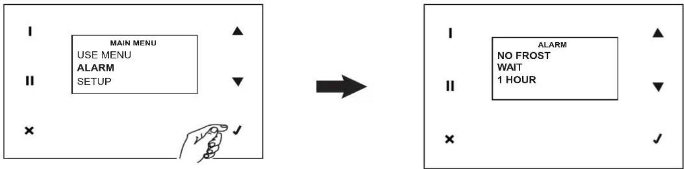
flowchart
graph LR
    A["MAIN MENU\nUSE MENU\nALARM\nSETUP"] --> B["→"]
    B --> C["ALARM\nNO FROST\WAIT\n1 HOUR"]
Setup
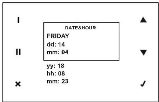
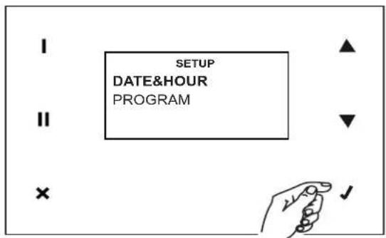
You can access the Date and Hour setting and weekly programming with this option

DATE&HOUR
Set the Date and Time as follows:
- Search for the variable you wish to change, pressing
- Select the variable, pressing
- Search for the desired value, pressing ▲ or ;
- Store the selected value, pressing
- Return to point 1 and so on.



ENGLISH
PROGRAM
With this option, you can access operating speed setting for six time slots (with start and end times) for each day of the week and for two pre-set intervals: Monday-Friday and Saturday-Sunday
Proceed as follows for all desired days and time slots:
NOTE
At the specified intervals, however, the speeds can be changed manually in the "HOME" page, in that case: the message "Prg" will flash
for 30 minutes after which it will return to work at the speed set in the hourly programming, if during the 30 min any other function that modifies the speed intervenes, the 30 min count is reset.

flowchart
graph TD
    A["SETUP\nDATE&HOUR\nPROGRAM"] --> B["PROGRAM\nMONDAY\nTUESDAY\nWEDNESDAY\nTHURSDAY\nFRIDAY\nSATURDAY\nSUNDAY\nMON-FRI\nSAT-SUN"]
    B --> C["MONDAY\nTimeslot1\nTimeslot2\nTimeslot3\nTimeslot4\nTimeslot5\nTimeslot6"]
    C --> D["MONDAY TimeSlot1\n00:00\n07:30\nNIGHT"]
    A -->|✓| E["✓"]
    B -->|✓| F["✓"]
    C -->|✓| G["✓"]
    D -->|✓| H["✓"]
NOTE
The time bands of MON / FRI or SAT / SUN overwrite the single days, during the setting change first the general time bands, and then set the daily ones. If they are subsequently changed again, the LUN / VEN and SAB / DOM bands will overwrite the daily ones
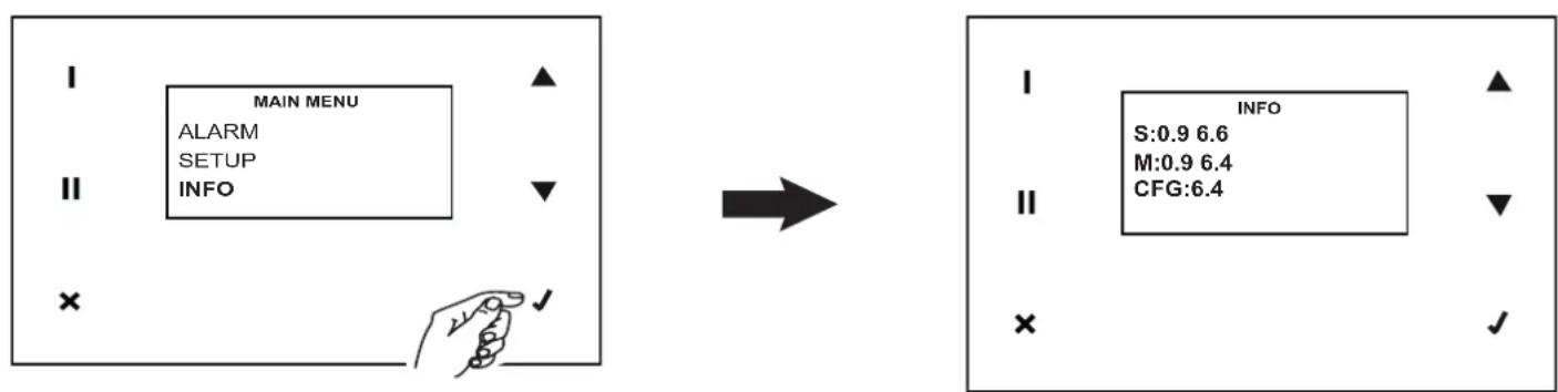
Info
You can view the following system information with this option: HMI, Board firmware, Configuration files
flowchart
graph LR
    A["MAIN MENU"] --> B["INFO"]
    style A fill:#f9f,stroke:#333
    style B fill:#ccf,stroke:#333
15 Maintenance and cleaning
15.1 Filters:
Recommended maintenance timetable: in general, the level of air pollution depends on the geographical installation area, and therefore filter duration is variable. With these considerations in mind, the maintenance alarms for filters can however be set as follows (see also the "Use" paragraph):
- pre-alarm: activates filter check and cleaning warning
• alarm: activates the filter saturated warning
The counter will also be reset when a filter error is reset.
NOTE: Failure to clean or replace filters causes serious problems with system efficiency, including:
- Increase in pressure losses in the air circuit and reduction of air flow
- Consequent decrease in machine yield and worsening of comfort in the environment
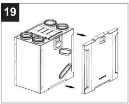
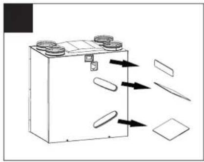
Follow the instructions below to access the filters:
- disconnect the device from the electrical mains;
- remove the panel; (fig.19)
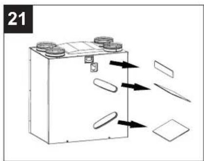
- remove the filters from the device (fig. 20, 21)
natural_image
Technical line drawing of a portable electronic device with internal compartments and external casing (no text or symbols)
natural_image
Diagram of a battery with arrows indicating flow or movement, showing components like wheels and sheets (no text or symbols)- Clean the filters using a vacuum cleaner. It is preferable to replace the filters after some cleanings, and at least 1 time a year.
- Re-install filters
In the event of prolonged downtime of the device, remove the filters to prevent the risk of their damage induced by any formation of condensation.
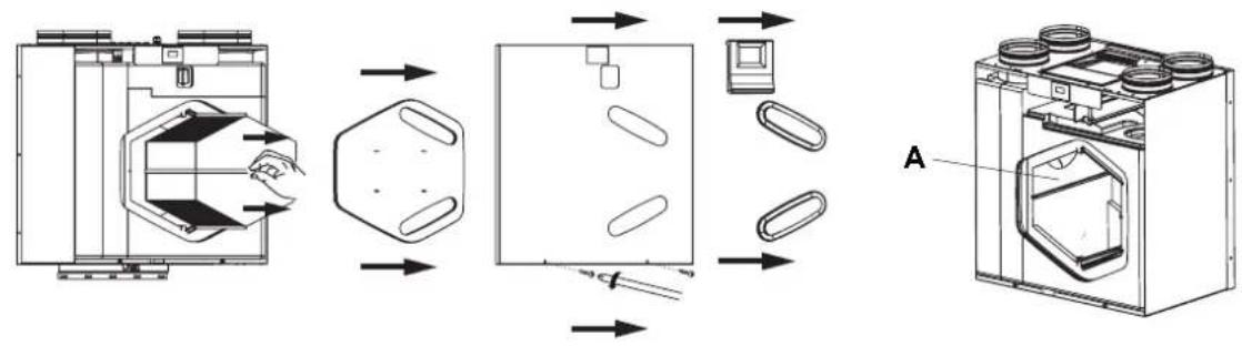
15.2 Heat exchanger
Checking and any cleaning of the exchanger must be carried out by professionally qualified personnel, preferably every 3 years. For cleaning, use a vacuum cleaner.
Follow the instructions below to access the exchanger:
- disconnect the device from the electrical mains;
- Remove the exchanger (fig. 22)
- Clean the exchanger with a vacuum cleaner
- Re-install the exchanger; when performing this operation, make sure that the gaskets inside the device remain in position (fig.22 - A);
22
flowchart
graph LR
    A["Raw Material"] --> B["Process Step"]
    B --> C["Product Packaging"]
    C --> D["Final Product Box"]
    style A fill:#f9f,stroke:#333
    style B fill:#ccf,stroke:#333
    style C fill:#cfc,stroke:#333
    style D fill:#fcc,stroke:#333
ENGLISH
15.3 External cleaning
Follow with the instructions below to clean the external parts of the device:
- disconnect the device from the electrical mains;
- use a slightly damp, soft cloth only;
- do not use abrasive and/or corrosive products;
- do not use a cloth that is rough and/or too wet with water. Water inside the product could cause serious damage.
16 Disposal
This product complies with Directive 2012/19/EU on the management of waste electrical and electronic equipment (WEEE).
The crossed-out wheeled bin symbol on the appliance indicates that, at the end of its life, the product should not be discarded together with household waste but must be taken to a separate collection point for electrical and electronic equipment. This will avoid negative effects on the environment and health, and will encourage correct treatment, disposal and recycling of the materials from which the product is made.
Contact the municipal authority for the location of this type of facility. Alternatively, the distributor is obliged to take back the appliance to be disposed of free of charge in exchange for the purchase of an equivalent appliance.

CONDICIONES GENERALES DE GARANTÍA
GENERAL WARRANTY CONDITIONS
1 - Baxi Climatización, S.L.U., in accordance with Royal Legislative Decree 1/2007 of November 16, is liable before the user for the non-conformity of their products occurring during the first two years as of the purchasing date reflected on the purchasing invoice.
Unless there is evidence to the contrary, it shall be presumed that the product's non-conformities occurring within six months of the purchasing date were already present when the product was commissioned.
Baxi Climatización, S.L.U., in addition to the legal warranty mentioned in the previous paragraphs, also offers an additional and voluntary commercial warranty, which presumes the product's non-conformities occurring within two years as of the purchasing date were already present when the product was commissioned. Consequently, Baxi Climatización, S.L.U. offers a 2-year FULL warranty on spare parts.
2 - The warranty shall not be applicable to the following cases:
a) Fault or malfunction caused by improper installation according to the installation instructions or non-compliance with the regulations in force in the installation of the appliance.
b) Improper transport or storage, corrosion, abrasion, lack of cleaning, lack of maintenance, misuse or abuse, fire, frost, normal wear and tear, or any other reason not related to the appliance.
c) Intervention of unauthorised personnel or use of non-original spare parts.
d) Use of unsuitable accessories or when the fault is a consequence of the installation structure in which the product is integrated, or caused by any other external element affecting it.
e) When it is verified that the products have been in operation for a period longer than the one covered by the warranty.
f) Direct exposure to water splashes and existence of leaks, deformations, or breakage not attributable to manufacturing defects (excess pressure due to installation defects, etc.).
3 - The warranty shall not cover expenses derived from uninstallation, construction, demolition, elevation, transport, or dismantling in the cases of areas difficult to access. Additionally, it shall not cover the expenses derived from the disassembly of items such as furniture, cabinets, etc., which hinder free access to the appliance or its components.
4 - This certificate, duly completed and stamped by the installer, must be submitted in order to request any assistance covered under the warranty.
5 - In particular, Baxi Climatización, S.L.U. shall not be liable for damages to persons or things that may be caused by any of the reasons specified in section 2 above.
6 - Any other claim not specified in the previous sections is excluded unless expressly provided by law.
7 - This warranty shall not affect the rights that the consumer has in accordance with Royal Legislative Decree 1/2007 of November 16, Guarantees in the Sale of Consumer Goods and other applicable regulations.
8 - If you wish to file a claim, please contact the dealer where you purchased the product. If filing a claim through this channel is not possible, please contact Baxi Climatización, S.L.U.
Recommendations:
Before using the appliance, carefully read the product instructions.
Use our authorised Baxi Heating service to carry out the commissioning, adjustment and, periodic maintenance of your appliances.
Subscribe to a maintenance plan with our authorised Baxi Heating service to ensure correct operation and minimum consumption of your appliance at all times.
BAXI
Tel. + 34 902 89 80 00
www.baxi.es
informacion@baxi.es


- Residential heat recovery
- ESPAÑOL
- índice
- Información general....3
- Funcionamiento
- Motores
- RESET FIL
- POSTTEMP
- Setup
- PROGRAM
- Limpieza externa
- Esquema de funcionamento do sistema
- Funcionamento
- LIFE TIME
- PORTUGUES
- General informations....57
- Product description 58
- 10Installation 63
- System operating diagram....65
- 12Electrical connections....66
- 13Operation 67
- 14Use....69
- Maintenance and cleaning 81
- Disposal 82
- General informations
- Description of the symbols
- Obligation.
- Purpose of the manual
- Product description
- Structure and equipment
- Compliance
- Safety/Warnings
- OBLIGATION
- PROHIBITION
- DANGER
- Technical data
- Fan performance graph
- Dimensions
- General warnings for the installer
- Installation
- Assembly
- Connecting the condensate drain tube
- ENGLISH
- Piping connection
- Stale air supply toward outside
- Fresh air from outside
- Stale air exhaust from room (extract)
- Fresh air supply to room
- System operating diagram
- Electrical connections
- Operation
- Motors
- Filters:
- Bypass
- Automatic defrost
- USB outlet
- Holiday
- Post-ventilation
- Program
- Use
- General
- Meaning of icons buttons in the touch area:
- CONTROL PANEL FUNCTIONS
- Main menu
- Use menu
- Installer functions (password 023)
- SET UP BYPASS
- MBUS ID
- SPEED
- VSUP VEXH
- LANGUAGE
- NO FROST
- POSTHEAT
- COM ADD
- COM PAR
- User functions (password 013)
- Alarm
- Filters:
- T ext probe
- T int probe
- Texh probe
- DATE&HOUR
- NOTE
- Info
- Maintenance and cleaning
- Filters:
- Heat exchanger
- External cleaning
- Disposal
- CONDICIONES GENERALES DE GARANTÍA
- GENERAL WARRANTY CONDITIONS
Brand : Baxi
Model : Sila RCV 400
Category : Fan