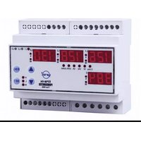
EPM-04-DIN - Measuring equipment ENTES - Free user manual and instructions
Find the device manual for free EPM-04-DIN ENTES in PDF.


| Product Type | DIN-rail mounted energy meter |
| Model | EPM-04-DIN |
| Brand | ENTES |
| Category | Measuring equipment |
| Dimensions (W x H x D) | 72 x 90 x 63 mm (4 modules) |
| Weight | Approx. 150 g |
| Power Supply | 230 V AC, 50 Hz |
| Display | LCD, 6+2 digits |
| Functions | Active energy (kWh), reactive energy (kVArh), power (W), voltage (V), current (A), frequency (Hz), power factor |
| Accuracy Class | Class 1 (active energy) per IEC 62053-21 |
| Rated Current | 5 A (secondary of CT) |
| Frequency | 50 Hz ±10% |
| Communication | Pulse output (LED or relay) |
| Mounting | DIN rail EN 60715 (TH35) |
| Operating Temperature | -10°C to +55°C |
| Storage Temperature | -25°C to +70°C |
| Protection Degree | IP20 (front), IP10 (terminals) |
| Maintenance | Clean with dry cloth; do not use liquids |
| Safety | Install by qualified personnel; disconnect power before servicing |
| Spare Parts | No user-serviceable parts; contact supplier for replacement |
| Reparability | Non-repairable by user; must be replaced if faulty |
| General Information | For indoor use only; comply with local electrical regulations |
Frequently Asked Questions - EPM-04-DIN ENTES
User questions about EPM-04-DIN ENTES
0 question about this device. Answer the ones you know or ask your own.
Ask a new question about this device
Download the instructions for your Measuring equipment in PDF format for free! Find your manual EPM-04-DIN - ENTES and take your electronic device back in hand. On this page are published all the documents necessary for the use of your device. EPM-04-DIN by ENTES.
USER MANUAL EPM-04-DIN ENTES
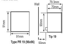
Panel Cut-out
Summary of the Contact Operations *
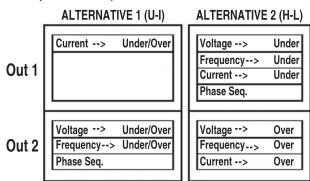
flowchart
graph TD
    subgraph OUT1
        A["Current --> Under/Over"]
        B["Voltage --> Under/Over"]
        C["Frequency --> Under/Over"]
        D["Phase Seq."]
    end
    subgraph OUT2
        E["Voltage --> Over"]
        F["Frequency --> Over"]
        G["Current --> Over"]
    end
    A --> H["ALTERNATIVE 1 (U-I)"]
    B --> I["ALTERNATIVE 1 (U-I)"]
    C --> J["ALTERNATIVE 1 (U-I)"]
    D --> K["ALTERNATIVE 1 (U-I)"]
    E --> L["ALTERNATIVE 2 (H-L)"]
    F --> M["ALTERNATIVE 2 (H-L)"]
    G --> N["ALTERNATIVE 2 (H-L)"]
    H --> O["Voltage --> Under"]
    I --> P["Voltage --> Under"]
    J --> Q["Voltage --> Under"]
    K --> R["Voltage --> Under"]
    L --> S["Voltage --> Over"]
    M --> T["Voltage --> Over"]
    N --> U["Voltage --> Over"]
* Valid for EPM-04C/04CS
Connection Diagram


flowchart
graph TD
    A["PR-19"] --> B["Current Measurement Inputs"]
    B --> C["Output Relay"]
    C --> D["Auxiliary Supply"]
    D --> E["Output"]
    style A fill:#f9f,stroke:#333
    style B fill:#ccf,stroke:#333
    style C fill:#cfc,stroke:#333
    style D fill:#fcc,stroke:#333
    style E fill:#ffc,stroke:#333
• Available only for EPM-04C/04CS
** Available only for EPM-04CS
Note: For CT-25 models:
k: When CT-25 is used, Red cable is connected to k terminal.
I: When CT-25 is used, Black cable is connected to I terminal.
A4034 / Rev.8
MULTIMETER
EPM-04 / 04C / 04CS
INDEX
| Precautions for Installation and Safe Usage. | |
| Front Panel and Usage of Buttons | 1 |
| General Information and Applications | 1 |
| Using the Buttons | 1 |
| Transformer Menu (Cr / Im) / Utr (ConnElction) | |
| User Password Settings (Pin Menu). | 2 |
| Activating the User Password (Pin Act Menu). | 2 |
| Changing the User Password (Pin Chg Menu) | 2 |
| Output Setting Menu | 3 |
| Current Setting Menu (SP Current Menu) | |
| High/Low Current Settings (H-H, H-L, SP Cur Lo Menu). | 4 |
| Hysteresis Settings for High/Low Currents (I-H, Hys, I-L, Hys Menu). | 5 |
| Delay-on Time for High/Low Currents (I-H ond., I-L ond. menu). | 6 |
| Delay-off Time for High/Low Currents (I-H ond., I-L ond. menu). | 7 |
| Start and Auto Function (Start and Auto FS Menu). | 8 |
| Instant Trip Function (CU inS trP Menu). | 9 |
| Voltage Setpoint Menu (SP Volt Menu). | 10 |
| High/Low Current Settings (H-H, H-L, SP Unl, Lo Menu). | 11 |
| Hysteresis Settings for High/Low Voltages (U-H, Hys, U-L, Hys Menu). | 12 |
| Delay-on Time for High/Low Voltages (U-H ond., U-L ond. menu). | 13 |
| Delay-off Time for High/Low Voltages (U-H old, U-L old. menu). | 14 |
| Frequency Menu | |
| High/Low Frequency Settings (Frq H, Frq Lo Menu). | 15 |
| Hysteresis Settings for High/Low Frequencies (F-H, F-L, F-HyS). | 16 |
| Delay-on / Delay-off Time for High/Low Frequencies (Frq and, Frq, eFd). | 17 |
| Phase Select (Voltage Spectrum Mode) and Instant Trip (Use in SP/PT Menu) | |
| Erasing the Max., Min and Max. Demand Values (Reset Menu). | 18 |
| Demand Time for Demand and Max. Demand (OE T menu). | 19 |
| Communication Menu (RS-RBS). | 20 |
| Technical Features and Default Factory Settings | |
| Connection Diagram | 21 |
| Output, SP Current and SP volt menus are available for EPM-04C/04CS, RS-485 menu. | |
PRECAUTIONS FOR INSTALLATION AND SAFE USE
In CT-25 (120A) compliant models, only CT-25 current transformer must be used.
Must be used. Other type of CT's have a high risk to damage to device.
Failure to follow those instructions will result in death or serious injury.
- Disconnect all power before working on equipment.
- When the device is connected to the network, do not remove the front panel.
- Do not try to clean the device with solvent or the like. Only clean with dry
cloth.
- verify correct terminal connections when wiring.
- Electrical equipment should be serviced only by your component seller.
- Only for rack panel mounting.
- Fuse must be F type and limit value doesn't exceed 1A.
- No responsibility is assured by manufacturer or any of its subsidiaries
for any consequences arising out of the use of this material.


1 ...... Phase LEDs: The LEDs turn on when the voltage value, which is applied
to one of the current inputs, reach 30 V
2 ...... First display's k LED (for L1). Measurement parameter is the unit of kilo
when LED is turned on. ie: kA, kV
3 ..... Display for L1.
4 ...... Second display's k LED (for L2). Measurement parameter is the unit of kilo
when LED is turned on. ie: kA, kV
5 ..... Display for L2.
6 .... Third display's k LED (for L3). Measurement parameter is the unit of kilo
when LED is turned on. ie: kA, kV
7 ..... Display for L3.
8 ...... Displays network frequency when Hz LED is turned on.
9 ...... k LED for neutral current. Measurement parameter is displayed in unit of
kilo when this LED is turned on.
10 ..... Display for neutral current and frequency (for EPM-04C/04CS).
11 ...... First warning output LED (Out1). Turned on when the output is activated.
12 ...... Second warning output LED (Out2). Turned on when the output is activated.
13 ...... Over current / voltage warning output for L1. (EPM-04C/04CS)
14 .... Low current / voltage warning output for L1. (EPM-04C/04CS)
15 ...... Over current / voltage warning output for L2. (EPM-04C/04CS)
16 ..... Low current / voltage warning output for L2. (EPM-04C/04CS)
17 ...... Over current / voltage warning output for L3. (EPM-04C/04CS)
18 ..... Low current / voltage warning output for L3. (EPM-04C/04CS)
19 ...... Over current / frequency warning output for frequency and neutral current
(EPM-04C/04CS).
20 .... Low current / frequency warning output for frequency and neutral current
(EPM-04C/04CS).
21 ...... Monitoring the L1, L2, L3 voltages values when V LED is turned on and
displays the frequency in 4th display.
22 ...... Monitoring the L1, L2, L3 currents values when A LED is turned on and
displays the neutral current in 4th display
23. Indicates the activating delta connection when▲ is turned on. Neutral
as well indicated the activating solid connection where is called on neutral current protection is deactivated even if is activated.
24 ..... H LED for max. instant current and voltage. Max. instant currents and
voltages are displayed when this LED is turned on.
25 ..... L LED for min. instant current and voltage. Min. instant currents and
voltages are displayed when this LED is turned on.
26 ..... M LED for max. demand. Max. demand values are displayed when this
LED is turned on.
27 ...... SET button. It is used to enter into the menu and to save the values.
If SET button is pressed for 3 sec. in the measurement mode, you can
enter into menus. This button is used for monitoring the max. (H), Min
(L) current values and max. demand values in measurement mode.
28 ...... Downward selection button
29 ...... Upward selection button.
30 ...... ESC button. Escaping from the menu. And also used for switching off the
Latch function while this function has activated.
General information
EPM-04/04C/04CS is designed for measuring Phase current, frequency, neutral
current and voltages (Phase-Phase and Phase-Neutral) in a
3-Phase system.
EPM-04C/04CS
Device has 2 warning output which named as Out1 and Out2. (NO-Normally
Open) Please refer to "Output" menu for the functions of the relays.

MULTIMETER EPM-04 / 04C / 04CS
Below measurement and application can be implemented with EPM 04/04C/04CS
LPM 04/04/0408
1) Phase currents (IL), Neutral current (IN), Phase-Phase and Phase-Neutral voltages can be measured.
2) Existence of live phases can be observed by L1-L2-L3 LEDs on the device.
3) Min. and max. values for measured currents and voltages can be monitored with only one button.
4) Max. demand values for measured current can be monitored. demand
time can be defined in "dE ti" menu.
5) A 4 digit password can be defined from pin menu in order to prevent the change of settings by unauthorized person.
change of settings by unauthorized person. 6) Current transformer ratio is programmable (1 2000)
Current transformer ratio can be programmed in term of "turn number"
between 1.....20 (for CT-25 adapted devices). Voltage transformer ratio in programmable (0.1 - 4000)
voltage transformer ratio is programmable. (0.1 .... 4000) 7) A user defined measurement range is used for monitoring the voltages
and currents; and Out1 & Out2 outputs are used for warning the user and
disconnecting the device in case of exceeding the limits of measurement
8) In case of using the device for measuring the current values of motors etc.
start delay (AUto rSt) function can be used for preventing the equipment
against the improper tripping, which is because of the demurrage current.
3) when a failure has occurred use the Latch function, in order to keep the device with saving its position (Latched), even if the failure conditions are
removed.
7th, 8th and 9th subjects are valid for EPM-04C/04CS.
Using the Buttons:
Using the Buttons: Some buttons and button groups are used for the below special function
Some buttons and button groups are used for the below special function when device is in the measurement mode (Without selecting a menu).
Monitoring for phase currents (A LED is activated) or phase voltages
(2) Monitoring for phase currents (V LED is activated) or phase voltages (V LED is activated).
Used for changing the menu settings and parameters in programming
mode.
: Used for monitoring min. / max. currents and voltages or max. demand
values. Switching to the programming mode if it pressed for 3 sec. In
programming mode; it is used for switching to the menu and saving
changes for the parameters.
(ESC): Switching to the previous menu and escaping the programming menu without saving the changes.
If the Latch function is turned on (EPM-04C/04CS): output will be
released when current(s) of system is exceed the defined values
When the system's current turns back to normal values then output doesn't react. Output can be triggered by the "ESC" button.
doesn't react. Output can be triggered by the ESC button. Commissioning the EPM-04C/04CS and menu setting:
Energize the device after implementing the connections respected to the
user manual.
Enter the proper menu settings in order to correct measurements and applications.
applications. Current Transformer Ratio Setup:
In this menu, current transformer ratio is set between 1 - 2000
(This menu is not available in the devices which are adapter
F0 with CT-25.)
Note: If the current transformer is not used between the system and device, current transformer ratio is entered as '1'.
Example: If a current transformer which has a ratio of 30/5A i
used between the system and device;
Current transformer ratio is entered as = 30/5 = 6
SET Press SET button for 3 sec. (IrA Fo menu is displayed)
Press SET button; trA Fo Ctr menu is displayed (In CT-25 adapted devices, trA Fo trp is displayed instead.)
(BET) (Not: trA Fo Utr or Con nEC to n menu can be displayed by scrolling
Press SET button. Blinking the first digit of displayed value appear ("trA Eq Ultr" or "Con nEC big p" menu can be
Enter the blinking digit value by scrolling
UP/DOWN buttons. Switch to the other digits by using SET buttons, up ESC button
digits by using SET button, use ESC button to go to previous digit. After you entered
SET the last digit press SET button, "trA Fo Ctr" → LCF
Is displayed. (Data is entered but is not activated yet. For activating the new data
please follow the below steps).
ESC Press ESC button one by one until
"SAU E SET yES" is displayed.
Press SET button. When "SAU E ErH Fo LEr"
SET YES IS displayed (If you press ESC button or choose "no")
SET PRICE AND ACTION OF CHECKS: No option instead of "yES" then new
data will be cancelled and previous value will be activated)
previous value will be activated.
Programming the Turn Number: This menu is available for CT-25 adapted devices. User defines
turn number, which is the number of how many tour the current
to cable has rounded into the CT-25. Numbers can be selected
between 1-20. Greater the number of turn means greater the conductivity
tco sensitivity.
E. W.
1 2 3 4 5 6 7 8 9 10 11 12 13 14 15 16 17 18 19
In this menu, voltage transformer ratio is set between 0000,1 - 4000,0.
Note: If the voltage transformer is not used between the system and
voltage transformer ratio is entered as '1'.
Example: If a voltage transformer which has a ratio of 34.5KV/100V is used between the system and device, Voltage transformer ratio
is used between the system and device, voltage transformer ratio is entered as 345. (34500/100)
Selection the Connection
Selecting the Connection Type :
Connection can be selected as Star or Delta in this menu
Connection can be selected as Qal of Delta in this menu.
Phase-Neutral voltage monitoring can be implemented if the "Star"
- Holde Neutral Voltage Monitoring Start-Be Implemented in the "Star" connection is selected.
[Non-Text]
Phase-Phase voltage monitoring can be implemented if the "Delta"
connection is selected.
NOTE: When the "Delta" connection is selected, "neutral current
NOTE: When the "Delta" connection is selected, "neutral current monitoring" can not be implemented even if it is activated.
monitoring can not be implemented even if it is activated.
User Password Setup:
In this menu user password is defined and activated. You must define and activate a 4-digit user password for preventing device
You must define and activate a 4-digit user password for preventing device settings from the illegal usage.
There are 2 sub menu in the Pin menu

Activating the user password
This menu is used for activating the user password.
After the user password is activated for entering to the menus; if the button is pressed for 3 sec, while the instant values
the battery is processed for 6 units, while the instant value are observed, user password is required. If the user password
s entered wrong device does not latch.
Vote: Factory default value of user password is "0000"
[Non-Text]
[Non-Text]
ing the user password, in the measurement mode
T button for 3 sec. (trA Fo menu is displayed)
[Non-Text]
[Non-Text]
"Pin" menu by scrolling UP/DOWN buttons
[Non-Text]
ET button (Pin ACT IUA tE is displayed.)
T button. Blinking the first digit of displayed value appears
- 1.2 1.3 1.4 - 1.5 - 0.9 0.8 0.7 - 0.6 - 0.8 0.7 0.6 - 0.5 - 0.7 0.6 0.5 - 0.4 - 0.6 0.5 0.4 - 0.3 - 0.5 0.4 0.3 - 0.2 - 0.4 0.3 0.2 - 0.1 - 0.3 0.2 0.1 - 0.0 - 0.2 0.1 0.0 - 0.0 - 0.1 0.0 0.0 - 0.0 - 0.0 0.0 0.0 - 0.0 - 0.0 0.0 0.0 - 0.0 - 0.0 0.0 0.0 - 0.0 - 0.0 0.0 0.0 - 0.0 - 0.0 0.0 0.0 - 0.0 - 0.0 0.0
the blinking digit value by scrolling OWN buttons. Switch to the other
OWN Buttons: SWITCH TO THE OTHER by using SET button, use ESC button
to previous digit. After you entered at digit press SET button, "Run ACT"
displayed, "on" can be selected by
ng UP/DOWN buttons. (Data is
ed but is not activated yet. For ing the new data please follow the
ing the new data please follow the steps).
(1)
C button one by "SALLE SET vES" P in k BCT k IWR k
SAO E SET YES yed.
15
I button. When SET vES" is
d (If you press
on or choose "no" option instead of "yes" then new data called and previous value will be activated?
dened and previous value will be activated).
Changing of User Password
This menu is used for changing the user password
Note: Factory default value for user password is "0"
[Non-Text]
[Non-Text]
[Non-Text]
vating the user password. in the measurement mo
n SET button 3 sec. (trA Eo menu is displayed.)
's SET Button 5 sec. (iTA TO menu is displayed.)
the "Pin" menu
crolling P in LAR nSE
DOWN buttons.
o SET button k Multiimeter Auto E76-1435
SET button CT IUA TE is
(1) 0.00
(1) 2017年1月1日
the "Pin CHA n9E" menu by scrolling UP/DOWN button
MULTIMETER EPM-04 / 04C / 04CS

ESC button or choose "no" option instead of "vES" then new data will be cancelled and
previous value will be activated).

Serial Communication (for EPM-04CS) EPM-04S have MODBUS RTU communication protocol which is optical isolated. All measured parameters can be transfer to the computer. Transformer ratios and communication parameters can be set. Saved values can be reset.


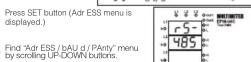


Enter the parameter values by scrolling UP/DOWN buttons (001...247 / 2400...38400 / no, EUEn, odd).

Press SET button, "Adr ESS / bAU d / PAnty" is displayed. (Data i entered but is not activated yet. For activating the new data please follow the below steps)

Press ESC button one by one until "SAU E SEt yES" is displayed. Press SET button. When "SAU E SEt yES" is displayed (If you press ESC button or choose "no" option instead of "yES", then new data wi
MODBUS RTU PROTOCOL (Available only for EPM-04CS)


The T times corresponds to a time in which data must not be exchanged on the communication bus to allow the connected devices to recognize the end of one message and the beginning of another. This time must be at least 3.5 characters at the selected baud rate. Adress range (1-247) is address of the connected device. The data field contains data sent to the slave by master or data sent to master by slave.
CRC is a error check method by using MODBUS RTU protocol and consists of 2 bytes.
Available
Read Hole
Read Hold (03) function is used for reading measured values and set value. If any request of reading of a register, excepted mentioned in register table, device will send an error message.
For example to read phase1 voltage by sending a message to the device.
01 03 00 01 Device 03 Functio
00 MSB a 00 LSB ad 00 Registe
02 Regist XX CRC M XX CRC I
Preset Single Register (06) function is used for writing the setting values, erasing the energy counter or resetting the min., max., max. demand values. Current transformers ratio can be set 0-2000, voltage transformer ratio can be set 1-40000.
i.e. Settir 01 06 80 01 Device
06 Functio 80 MSB a 02 LSB ad
00 Data N 64 Data L XX CRC M
XX CRC L Preset Mu i.e. Setting
01 10 80 00 00 02 04 00 C8 00 64 XX XX
Rated Voltage (Un) Operating frequency (f)
Auxiliary Supply Power Consumption Measuring Input Power Consumption Measurement range
Current Voltage
Close
Class Current Transformer Ratio Turn number for CT-25 adapted models Voltage Transformer Ratio
voltage Trans Max. Ctr x Vt
Communications (for EPM-04CS) : MODBUS RTU (RS 485)
Baud Rate (for EPM-U4CS)
Address (for EPM-04CS) Parity (for EPM 04CS)
Output Relays(for EPM-04C/04CS): 2 NO, 250 V AC, 5A, 1250 VA
Ambient Temperature Display
Display : Red LED display Dimensions : PR-19, PK-26
Equipment Protection Class : Double Insulation - Class II (☐)
Ray Protection Class : IR 40
Box Protect Terminal Pr
Box Materia
Mounting
Wire Cross section (for terminals)
weight
Mounting Category
Panel Size
Default Settings
.../5A type
Ctr - 0001
Utr - 0001
trn - 01 CoreFC SIA
Connect -
Pin Act - of
Pin - 0000
dt - 1
UHI 1 2
U-H L-1 - 2
U-H L-3 - 25
U-H Hys - 1 U-H and - 0
U-H OFd - O
U-L L-1 - 18
U·L·L·2
CT-25 type
-
[Non-Text]
[Non-Text]
[Non-Text]
[Non-Text]
[Non-Text]
,
[Non-Text]
[Non-Text]
[Non-Text]
[Non-Text]
[Non-Text]
[Non-Text]
[Non-Text]
[Non-Text]
[Non-Text]
[Non-Text]
[Non-Text]
[Non-Text]
[Non-Text]
[Non-Text]
[Non-Text]
[Non-Text]
[Non-Text]
[Non-Text]
[Non-Text]
[Non-Text]
[Non-Text]
[Non-Text]
[Non-Text]
[Non-Text]
[Non-Text]
[Non-Text]
[Non-Text]
[Non-Text]
[Non-Text]
[Non-Text]
[Non-Text]
[Non-Text]
[Non-Text]
[Non-Text]
[Non-Text]
[Non-Text]
[Non-Text]
[Non-Text]
[Non-Text]
[Non-Text]
[Non-Text]
[Non-Text]
[Non-Text]
[Non-Text]
[Non-Text]
[Non-Text]
[Non-Text]
[Non-Text]
[Non-Text]
[Non-Text]
[Non-Text]
[Non-Text]
[Non-Text]
[Non-Text]
[Non-Text]
[Non-Text]
[Non-Text]
[Non-Text]
[Non-Text]
[Non-Text]
[Non-Text]
[Non-Text]
[Non-Text]
[Non-Text]
MULTIMETER
EPM-04 / 04C / 04CS


Setpoints for Frequency
In this menu, Frequency range can be defiend according to High and Low values of Frequency measurement.
If the frequency of the system decreases the Frq Hi value; output is switched on and LED is turned on. (Refer to Output menu) and H LED for frequency is turned off.
If the frequency of the system exceeds the high set value, H LED relating to frequency blinks, output switched off at the end of defined time (Frq Ond), LED turned off (Refer to Output menu) and H LED for frequency is turned on continuously.
If the frequency of system are under the high set value (Frq Hi) as a hysteresis (F-H HyS), output is turned on at the end of defined time (Frq oFd), LED is turned on and H LED is turned off, at the end of the adjusted time (Frq Ofd), output1 LED turns on and Hi LEDs turn off.
If the frequency of the system is over the low set value (Frq Lo), output is turned on, LED is turned on L LED is turned off.
If the frequency of the system decreases the low set value (Frq Lo), L LED blinks; output is turned off at the end of defined time (Frq ond), LED is turned off and L LED is turned on continuously.
If the frequency of the system is over the low set value (F-L HyS) as a hysteresis (Frq Hys), output is turned on at the end of defined time (Frq Ofd), LED is turned on and L LED is turned off.
Note: System frequency is measured for L1
There are 6 submenus.
Frq Hi, Frq Lo, F-H HyS, F-L HyS, Frq Ond, Frq oFd.

Max. value for system frequency, this value can be defined between 0...70.00 Hz. If the value is set to zero (0), the high frequency warning is disabled.

Min. value for system frequency, this value can be defined between 0...70.00 Hz. If the value is set to zero (0), the low frequency warning is disabled.

Note: Attention for common using of output and relay LED for voltage.

In this menu, required hysteresis value can be defined between 0...20.00 Hz. in order to switching off the "high frequency" warning.

In this menu, required hysteresis value can be defined between 0...20.00 Hz. in order to switching off the “low frequency” warning.

Delay-on time for activation of alarm for high and low frequency value. This value can be defined between 000.0..999.9 in term of second..

Delay-off time for disactivation of alarm for high and low frequency value. This value can be defined between 000.0..999.9 in term of second..

Phase sequence can be turned on/off in this menu. Inversed phase voltage which is applied to the measurement inputs (L1-L2-L3), can be monitored. Default setting is off. In order to let the device to warn user in case of inversed phase situation please change the off position as on in "UcL PHS SEq" menu. Phase sequence function is disabled if the selection is selected off.
L1, L2 and L3 LEDs blink and output output released immediately when "UoL PHS SEq" is turned on and phase sequence is inverted with any reason. Note: Output 2 is used if U-I is selected and Output1 is used if H-L is selected in Output menu for the Phase Sequence monitoring

Instant Tripping Function.
At position ON, if any VL-L / VL-N values exceeds 1.5 times of high voltages (UoL Hi L-1/L-2/L-3) values; the "voltage output" switches OFF instantly, output LED turned OFF and H LED, for related voltage, is turned ON. (Please refer to "Output".)
If any phase voltage decrease 0.5 times low voltages (UoL L-1/L-2/L-3); the "voltage output" switches OFF instantly, output LED turned OFF and Lo LED, for related voltage, is turned ON.
(Refer to Page-4 for "CUr inS trP", "AUt or St" and "UoL inS trP")
Reset function.
In this menu, values of min., max., max. demand are erased. It saves the instantaneously measured min. and max. values of the device into its memory. Please kindly look at to the section of FUNCTIONS OF BUTTONS for min. and max. values.
Note: Measured electrical parameters which are saved to the memory are not affected from the electric interruptions. In the rES Et HL or rES Et dE menu; when you choose yES and quit from all menus, if you confirm the changes, min., max. and max. demand values of all parameters are erased at the same time.
Press SET button for 3 sec. (trA Fo menu is displayed.)
Find rES Et menu by
scrolling UP-DOWN
buttons.


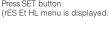





UP-DOWN buttons, other
can be selected. If you want to delete the value, choose YES,


utton, rES Et dE / rES Et HL is displayed. (Data is entered activated yet. Activating the new data, please below steps)

gutton one by one until "SAU F. SE1 vES" is displayed.

button. When "SALLE SET vES" is displayed (If you press

ution: When SAG E SET YES is displayed (if you press or choose "no" option instead of "vES" then new data will

of choose "No option instead of YES" then how data will and previous value will be activated).

Demand Time.
Max. Demand time can be defined between 01-60 minute in this


Find dE timenu by scrolling UP-DOWN


B. 2017-10-25, 2018-10-26, 2019-10-27


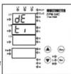

Enter the blinking digit value by scrolling UP/DOWN buttons. Switch to the other digits by using SET button, use ESC button to go to previous digit. After you entered the last digit press SET button, "dE b" is displayed. (Data is entered but is not activated yet. For activating the new data please follow the below steps).
MULTIMETER
EPM-04 / 04C / 04CS

Enter the old password by scrolling UP/DOWN/SET buttons.

Enter the new password by scrolling UP/DOWN/SET buttons.

Enter the new password again by scrolling UP/DOWN/SET buttons.


ESC button or choose "no" option inst


be cancelled and previous value will b


ut menu :

Out Relay function:
In this menu high-low or voltage-current monitoring is determined for Out1 and Out2 outputs.
determined for S&P Africa S&P outputs
Note: When U-I (voltage-current) is selected; Out2 is monitoring according to high or low voltage, frequency values and phase sequence, Out1 is monitoring according to high or low-current value.
When H-L (high-low) is selected; Out2 is monitoring according to high values for voltage, frequency and low-current, Out1 is monitoring according to low values for voltage or current.
Please refer to page 8 for a summary of the contact operations.
Out Latch function:
If the Latch function is turned on
OUT1-OUT2 outputs, which are released when a failure has occurred, keep remained at its position even if the failure is over. Pressed button in order to triggering the relay when the failure situation is removed.
If the Latch function is turned off
Released outputs triggered at the end of delay off time when
the failure situation is removed.
Out inverse function:
If "oUt inU ErS" function is selected off
Device is started with closed output contacts (out1, out2) in the normal network conditions according to settings. Otherwise devices started with open position of the contacts. Default setting is "off".
ET button for 3 secs. (trA Fo menu is displayed).

7 Find oUt PUT menu by scrolling UP-DOWN buttons.
Press SET button oUt rEL AY / 📄 out LAt CH / 📄 out inU ErS are displayed
Dress GET button, H1 blink in 4th display (SET blink for Alt & Alt
Press SET button, and a TURU F-0)
and OUTINOERS)

Select U-I or H-L by scrolling UP/DOWN buttons. (Select on or oFF for "oUT LAI CH" and "oUT inU ErS")

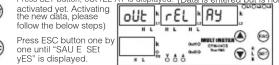
Press SET button. When "SAU E SET yES" is displayed (If you press ESC button or choose "no" option instead of "yES" then new data will be cancelled and previous value will be activated).
Programming "SP CUr rnt"
Using purposes of submenus of "SP CUr rmt" explained below
with details.

In case of using the device for measuring the current values of motors etc., start delay (AUto rSt) function can be used for preventing the equipment against the improper tripping, which is because of the demurrage current. If the system current decreases 50mAxCtr then start-up delay is resetted and related output detect the system automatically. This feature must be observed in case of using this function.

In this menu, high set points for current values are programmed. Hi values for IL1, IL2, IL3 and IN can be entered one by one. If all the current values are under the Hi value; Out1 output is switched on, LED of Output1 turned on and LED of H turned off.
If any current (IL1, IL2, IL3 and IN) exceeds the high set value, H LED blinks. Output 1 output switches off at the end of the defined time (I-H ond), Output 1 LED turned off and H LED turned on continuously.
If all currents (L1, IL2, IL3 and IN) are below the high set value (HI) as a hysteresis current (I-H HyS), output 1 output switches on at the end of the defined time (I-H Old), output 1 LED turned on and H LED turned off.
This menu has 7 sub menus. I-H L-1, I-H L-2, I-H L-3, I-H L-n, I-H HyS, I-H ond, I-H ofD Note: High Current values are programmed for IL1, IL2, IL3 and IN separately but I-H HyS (hysteresis), I-H ond (delay on time) and I-H ofD (delay off time) values are common and they have same values for IL1, IL2, IL3 and IN.

In this menu, low set points for current values are programmed. Lo values for IL1, IL2, IL3 and IN can be entered one by one. If all the current values are over the Lo value; Out1 output is switched on, LED of Output1 turned on and LED of L turned off.
If any current (IL1, IL2, IL3 and IN) exceeds the low set value, L LED blinks and Output 1 output switches off at the end of the defined time (-L ond), Output 1 LED turned off and L LED turned on continuously.
If all currents (IL1, IL2, IL3 and IN) are over the low set value (Lo) as a hysteresis current (I-L HyS), output 1 output switches on at the end of the defined time (I-L Old), output 1 LED turned on and L LED turned off.
This menu has 7 sub menus. I-L L-1, I-L L-2, I-L L-3, I-L L-n, I-L HyS, I-L ond, I-L ofD Note: Low Current values are programmed for IL1, IL2, IL3 and IN separately but I-L HyS (hysteresis), I-L ond (delay on time) and I-L ofD (delay off time) values are common and they have same values for IL1, IL2, IL3 and IN.
In this menu, max. current value for IL1 is programmed. The current value can be programmed between: 0,001....5,000 A (Ctr = 1); 000,1....120,0 A (for CT-25 adapted device trn=1). If the value is set to zero (0), the high current warning
If the value is set to zero (0), the high current warning is disabled (I-H L-2 and I-H L-3 are programmed similarly). Refer "SP Cur Hi" for details. In this menu, min. current value for IL1 is programmed. The current value can be programmed
programmed. The current value can be programmed between: 0,001....5,000 A (Ctr = 1); 000,1....120,0 A (for CT-25 adapted device trn=1). If the value is set to zero (0), the low current warning is disabled (I-L L-2 and I-L L-3 are programmed similarly). Refer "SP Cur Lo" for details.
In this menu, required hysteresis current for high current warning is programmed. (same for IL1, IL2, IL3 and IN.) The current value can be programmed between: 0,001....2,500 A (Ctr = 1).
000,1....60,00 A (for CT-25 adapted device trn=1) Refer "SP Cur Hi" for details. In this menu, required hysteresis current for low current warning is programmed.(same for IL1, IL2, IL2, IL3)
HYS IL3 and IN.) The current value can be programmed between: 0,001....2,500 A (Ctr = 1) 000,1....60,00 A (for CT-25 adapted device trn=1)
Refer "SP CUR LO" for details. Delay time for activating the output for high current warning. It is common for all currents (IL1, IL2, IL3 and IN) The value can be programmed between 000,0 and 999,9 in terms of seconds.
(Heter "SP Cur Hi" for details.) Delay time for activating the output for low current warning. It is common for all currents (IL1, IL2, IL3 and IN) The value can be performed between 000.0 and
ond The value can be programmed between 000,0 and 999,9 in terms of seconds. (Refer "SP Cur Lo" for details.) Delay time for releasing the output for high current
Delay time for releasing the output for high current warning. It is common for all currents (IL1, IL2, IL3 and IN) The value can be programmed between 000,0 and 999,9 in terms of seconds. (Refer "SP Cur Hi" for details.)
Delay time for releasing the output for low current warning. It is common for all currents (IL1, IL2, IL3 and IN) The value can be programmed between 000,0 and 999,9 in terms of seconds.
(Refer "SP Cur Lo" for details.) (Refer to Page-5 for Setting instructions)
MULTIMETER
EPM-04 / 04C / 04CS

C10
sen
•
ct
C
JCI
OCL
m = 311
广力云智慧零售收银系统
[Non-Text]
OW
BHF
HOC
m = 311
口
C
c5t
. 2c
广力云智慧零售收银系统
Dip
Please
principl
. . .
(on)
(off)
1
.
5A
4A
34
2A
LA
1A
IL1
1
单位:元
VIS-6
itch-off 5t
itch-on
itch stl
1
Sta
itch-on
itch-off
itch-cn
5.6.2
10
1
CU-
LUP
C
105
m2
L-0
ENT
The Ground Truth image displays a single, solid horizontal line. According to Rule 2 (UNDERSCORE & LINE RULES), this is a stylistic or background line, not a placeholder underscore. Therefore, the OCR result must ignore it and output nothing or only meaningful text. The provided OCR content is "____", which consists of four underscores. This is an incorrect interpretation of the line as a placeholder, violating the rule that stylistic lines must be ignored. The OCR has hallucinated underscores where none should exist based on the GT's visual context. Hence, the OCR result is inconsistent with the Ground Truth.
[Non-Text]
[Non-Text]
[Non-Text]
[Non-Text]
Programming "CUr inS trP", "AUt o rSt" and "UoL inS trP"

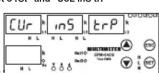

Press SET button for 3 se
(trA Fo menu is displayed)
(No text)
[Non-Text]
Find "SP CUr rmt / SP Uol
menu by scrolling UP-D


SET
SET
↓
[Figure]
▲
▲
(一)
T
A
(SET)
Press SET button (SP CI
menu is displayed.)
menu is displayed.)
(1) 2017年1月1日至2018年1月1日
图 1(2011) 6(2012)
Find [(CUR INS TRP) AUTO menu by scrolling UP-1
Trend by scrolling of
[Non-Text]
Press SET button [(CI
AUT o rSt on) / Uol, inS trP
Select "on" in order to ac
select "off" in order to dis
UP/DOWN buttons.
[Non-Text]
Press SET button. [(CU]
(Selection is entered bu
selection, please follow th
[Non-Text]
Press ESC button one b
[Non-Text]
Press SET button. When
ESC button or choose "r
be cancelled and previo
Programming "CDI
Programming SP
Using purposes of sub-
details.
The Ground Truth image displays a single, solid horizontal line. According to Rule 2 (UNDERSCORE & LINE RULES), this is a stylistic or background line, not a placeholder underscore. Therefore, the OCR result must ignore it and output nothing or only meaningful text. The provided OCR content is "____", which consists of four underscores. This is an incorrect interpretation of the line as a placeholder, violating the rule that stylistic lines must be ignored. The OCR has hallucinated placeholder underscores where none should exist in the GT. Hence, the OCR result is inconsistent with the Ground Truth.
广力云智慧零售收银系统
广力云智慧零售收银系统
广力云智慧零售收银系统
广力云智慧零售收银系统
co In this men
programme
Phase (acc
He!
BOL entered one
11
If all the volta
are under th
its LED turne
H LEDs are
If all the volta
are over five
are over the is switched
is switched to its LED turn
its LED turne ULLEDs are
H LEDs are
If all voltage
if all voltage the high set
the high set v relented out
released out off time" (U)
on time (U-1)
Output Year
Note: High
(Phase-Neu
HyS" (hyste
"Hi oFd" (de
parameters
Phase-Phas
When Conn
to Connec
U-H L-1, U-
according to
•
Example :
(with neut)
U-H L-2=25
and then th
(without neu
calculated t
calculated
NEW values, U H I 1 (L)
U-H L-T (L
U-H L-2 (L2
U-H L-3 (L3
U-H-HyS =
There are
U-H I-1
U H and
U*H 014,
[Non-Text]
[Non-Text]
[Non-Text]
[Non-Text]
[Non-Text]
[Non-Text]
[Non-Text]
[Non-Text]
[Non-Text]
[Non-Text]
[Non-Text]
[Non-Text]
[Non-Text]
[Non-Text]
[Non-Text]
[Non-Text]
[Non-Text]
[Non-Text]
[Non-Text]
[Non-Text]
[Non-Text]
[Non-Text]
[Non-Text]
[Non-Text]
[Non-Text]
[Non-Text]
[Non-Text]
[Non-Text]
[Non-Text]
[Non-Text]
[Non-Text]
[Non-Text]
[Non-Text]
[Non-Text]
[Non-Text]
[Non-Text]
[Non-Text]
[Non-Text]
[Non-Text]
[Non-Text]
[Non-Text]
[Non-Text]
[Non-Text]
[Non-Text]
[Non-Text]
[Non-Text]
[Non-Text]
[Non-Text]
[Non-Text]
[Non-Text]
[Non-Text]
[Non-Text]
[Non-Text]
[Non-Text]
[Non-Text]
[Non-Text]
[Non-Text]
[Non-Text]
[Non-Text]
[Non-Text]
[Non-Text]
[Non-Text]
[Non-Text]
[Non-Text]
[Non-Text]
[Non-Text]
[Non-Text]
[Non-Text]
[Non-Text]
[Non-Text]
[Non-Text]
[Non-Text]
[Non-Text]
[Non-Text]
[Non-Text]
[Non-Text]
[Non-Text]
MULTIMETER
EPM-04 / 04C / 04CS

In this menu, low set points for voltage values are programmed. Lo values for Phase-Neutral / Phase-Phase (according to Star / Delta selection) can be entered one by one.
If all the voltage values (Phase-Neutral / Phase-Phase) are over the Lo value; released output is switched on, its LED turned on (please refer "Output") and released L. LEDs are turned off.
If any of the voltage values (Phase-Neutral / Phase-Phase) decrease the Lo value, L LED blinks and related output is switched off at the end of “delay on time” (U-L ond), its LED turned off (please refer “Output”) and related L LED is turned on continuously. If all voltage (Phase-Neutral / Phase-Phase) values increase the low set value (Lo) as a hysteresis voltage (U-L HyS), related relay is switched on at the end of the “delay off time” (U-L ofd), its LED turned on (please refer “Output”) and L LED is turned off.
Note: Low Voltage values are programmed for (Phase-Neutral / Phase-Phase) separately but "U-L HyS" (hysteresis), "U-L ond" (delay on time) and "U-L ofD" (delay off time) values are common; these parameters have same values for Phase-Neutral / Phase-Phase. When Connection type (Star/Delta) is selected (refer to Connection menu), device will change the U-L L-1, U-L L-2 and U-L L-3 values automatically according to connection.
Example : If the connetion type is selected as Star (with neutral): U-L-Hvs=10V
U-L L-1=180V, U-L L-2=175V, U-L L-3=170V and then this connection type is selected as Delta (without neutral), device will change the values after calculated them according to Phase-Phase values. New values;
U-L L-1 (L1-L2 Phase to phase voltage) = 311 V
U-L L-2 (L2-L3 Phase to phase voltage) = 303 V
U-L L-3 (L3-L1 Phase to phase voltage) = 294 V
U-L-HyS = 10 V.
There are 6 submenus.
U-I I-1, U-I I-2, U-I I-3, U-I HvS.
U-I and U-I oEd
C
A
U-R High value for L1, when the Star is selected; high value for L1-L2, when the Delta selected can be defined in this menu.
0....300 for Star connection and 0....500 for Delta connection can be defined.
If the value is set to zero (0), the high voltage warning is disabled. Refer "SP Uol HI" for details.
[Non-Text]
Note: L2 and L3 phases can be programmed similarly.
广力云智慧零售收银系统
U-L Low value for L1, when the Star is selected; low value for L1-L2, when the Delta selected can be defined in this menu.
0....300 for Star connection and 0....500 for Delta connection can be defined
If the value is set to zero (0), the high voltage warning is disabled. Refer "SP Uol Lo" for details.
[Non-Text]
Note: L2 and L3 phases can be
[Non-Text]
(Refer to Page 4 for SR CUx H, SR CUx Le
[Refer to Page-4 for SP CU
[Non-Text]
•
U-H in this trend, required hysteresis voltage for high voltage warning is programmed. (same for Phase-Neutral/Phase-Phase.) 0....200V for Star connection and 0....700V for Delta connection can

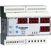
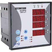
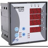
Brand : ENTES
Model : EPM-04-DIN
Category : Measuring equipment